

YSI 2900D, 2900M, 2950D-0, 2950D-1, 2950D-2 Operation And Maintenance Manual
...
YSI 2900 Ser ies
Biochemistry Analyzers
Operations and Maintenance Manual

Table of Content s
Introduction .................................................................................................................................... 5
1.
Description ................................................................................................................................. 5 1.1
User Features ............................................................................................................................ 5 1.2
Models ....................................................................................................................................... 5 1.3
2900 Series General Specifications .......................................................................................... 6 1.4
2960 Online Monitor Specifications ........................................................................................... 6 1.5
Monitor ................................................................................................................................ 6
1.5.1
1.5.2 Analog/Control .................................................................................................................... 7
2. Safety ............................................................................................................................................... 7
Important Safety Instructions ..................................................................................................... 7 2.1
Explanation of Symbols ............................................................................................................. 8 2.2
Getting Started ............................................................................................................................... 9
3.
Unpacking .................................................................................................................................. 9 3.1
Warranty Card ......................................................................................................................... 10 3.2
What You Need ....................................................................................................................... 10 3.3
Major Components .................................................................................................................. 10 3.4
Basic Setup ................................................................................................................................... 12
4.
Install Bottle Racks .................................................................................................................. 13 4.1
Right Side .......................................................................................................................... 13
4.1.1
4.1.2 Left Side (2950 models only) ............................................................................................ 14
Connect Printer ........................................................................................................................ 15 4.2
Connect AC Power .................................................................................................................. 15 4.3
Connect 2960 Online Monitor .................................................................................................. 16 4.4
Align Sipper ............................................................................................................................. 16 4.5
Configure Instrument Chemistries ........................................................................................... 19 4.6
Assign Chemistries to Probes ........................................................................................... 19
4.6.1
4.6.2 Assign Reagents ............................................................................................................... 22
Prepare and Install Buffer Solutions ........................................................................................ 24 4.7
Prepare Buffer ................................................................................................................... 25
4.7.1
4.7.2 Install Buffer Solution(s) .................................................................................................... 25
Install Calibrator Solution(s) .................................................................................................... 25 4.8
Install Membranes and ISEs .................................................................................................... 26 4.9
Enzyme Membranes ......................................................................................................... 26
4.9.1
4.9.2 Ion Selective Electrodes.................................................................................................... 27
Prime the Fluid System ........................................................................................................... 29 4.10
Check Probe Currents ............................................................................................................. 30 4.11
Biosensor Probes ....................................................................................................... 30
4.11.1
4.11.2 ISE Probes.................................................................................................................. 30
Enable 21 CFR Part 11 Mode ................................................................................................. 30 4.12
Running the Instrument ............................................................................................................... 30
5.
Perform Daily Operational Checks .......................................................................................... 30 5.1
Enzyme Membrane Integrity Test ..................................................................................... 31
5.1.1
5.1.2 Linearity Test ..................................................................................................................... 33
5.1.3 Results .............................................................................................................................. 33
Sample Preparation ................................................................................................................. 35 5.2
Run Batch ................................................................................................................................ 35 5.3
1

5.3.1
Create Batches ................................................................................................................. 35
5.3.2 Load Samples ................................................................................................................... 37
5.3.3 Start ................................................................................................................................... 39
5.3.4 Status ................................................................................................................................ 39
Run Stat ................................................................................................................................... 39 5.4
Results ..................................................................................................................................... 42 5.5
Online Monitor and Control......................................................................................................... 42
6.
2960 Installation....................................................................................................................... 43 6.1
Align Sipper ............................................................................................................................. 46 6.2
Sample Interface...................................................................................................................... 46 6.3
Sterilization ........................................................................................................................ 47
6.3.1
Electrical Interface ................................................................................................................... 47 6.4
Analog Outputs ................................................................................................................. 47
6.4.1
6.4.2 Pump Control Outputs....................................................................................................... 48
6.4.3 Auxiliary Connector / Signal List ....................................................................................... 48
Monitor Setup .......................................................................................................................... 48 6.5
Name ................................................................................................................................. 49
6.5.1
6.5.2 Flow Rate and Purge Time ............................................................................................... 50
6.5.3 Antiseptic ........................................................................................................................... 50
6.5.4 Filtrate Pump ..................................................................................................................... 51
6.5.5 Module............................................................................................................................... 51
Start Monitor ............................................................................................................................ 56 6.6
Manual Sample during Monitor Sess ion ........................................................................... 57
6.6.1
Stop Monitor ............................................................................................................................ 58 6.7
Control Setup ........................................................................................................................... 58 6.8
Control Type ...................................................................................................................... 58
6.8.1
Print Monitor Configuration ...................................................................................................... 67 6.9
System Configuration .................................................................................................................. 68
7.
Settings .................................................................................................................................... 68 7.1
System .............................................................................................................................. 68
7.1.1
7.1.2 Fluid Detection (Bottles) .................................................................................................... 70
7.1.3 Display............................................................................................................................... 71
7.1.4 Auto-Cal Settings .............................................................................................................. 73
7.1.5 Scheduler .......................................................................................................................... 74
7.1.6 21 CFR Part 11 ................................................................................................................. 76
7.1.7 Date/Time .......................................................................................................................... 81
Service ..................................................................................................................................... 82 7.2
Sipper ................................................................................................................................ 82
7.2.1
7.2.2 Pumps ............................................................................................................................... 85
7.2.3 Modules ............................................................................................................................. 86
7.2.4 Stirbar ................................................................................................................................ 87
7.2.5 Monitor .............................................................................................................................. 89
Data ......................................................................................................................................... 90 7.3
Plate .................................................................................................................................. 90
7.3.1
7.3.2 Monitor .............................................................................................................................. 92
7.3.3 Calibration ......................................................................................................................... 94
Help ......................................................................................................................................... 95 7.4
About ................................................................................................................................. 95
7.4.1
7.4.2 Software ............................................................................................................................ 96
7.4.3 FAQ ................................................................................................................................... 97
7.4.4 Training ............................................................................................................................. 97
2

Ethernet Port ............................................................................................................................ 98 7.5
LAN (Shared Network Connection) ................................................................................... 98
7.5.1
7.5.2 Router (Private Network Connection) ............................................................................... 98
7.5.3 Accessing Stored Data...................................................................................................... 99
8. Chemistry Setup ......................................................................................................................... 101
Sample Volume ..................................................................................................................... 101 8.1
Measurement Parameter Information .................................................................................... 101 8.2
Choline ............................................................................................................................ 102
8.2.1
8.2.2 Ethanol/Ethanol-HC ........................................................................................................ 103
8.2.3 Galactose ........................................................................................................................ 104
8.2.4 D-Glucose (Dextrose) ..................................................................................................... 105
8.2.5 L-Glutamate (L-Glutamic Acid) ....................................................................................... 106
8.2.6 L-Glutamine ..................................................................................................................... 107
8.2.7 Glycerol ........................................................................................................................... 108
8.2.8 Hydrogen Peroxide ......................................................................................................... 109
8.2.9 L-Lactate ......................................................................................................................... 110
8.2.10 Lactose ..................................................................................................................... 111
8.2.11 Methanol ................................................................................................................... 112
8.2.12 Sucrose ..................................................................................................................... 113
8.2.13 Xylose ....................................................................................................................... 114
8.2.14 Simultaneous Ammonium and Potassium ................................................................ 115
8.2.15 Simultaneous Glucose and L-Lactate ...................................................................... 116
8.2.16 Simultaneous Glucose and Sucrose ........................................................................ 117
8.2.17 Simultaneous Glucose and Xylose ........................................................................... 118
8.2.18 Simultaneous L-Glutamate and L-Glutamine ........................................................... 119
9. Operational Checks and Maintenance ..................................................................................... 119
Cleaning, Disinfecting, and Dec ontaminating ........................................................................ 119 9.1
Touch Panel .................................................................................................................... 119
9.1.1
9.1.2 Decontamination Procedures .......................................................................................... 119
Daily Maintenance ................................................................................................................. 120 9.2
Empty the Waste Bottle(s) .............................................................................................. 120
9.2.1
9.2.2 Check the Calibrator Bottle(s) ......................................................................................... 120
9.2.3 Check the Buffer Bottle(s) ............................................................................................... 120
9.2.4 Check for Leaks .............................................................................................................. 120
9.2.5 Clean up Spills ................................................................................................................ 120
9.2.6 Daily Operational Checks................................................................................................ 120
Monthly Maintenance ............................................................................................................ 120 9.3
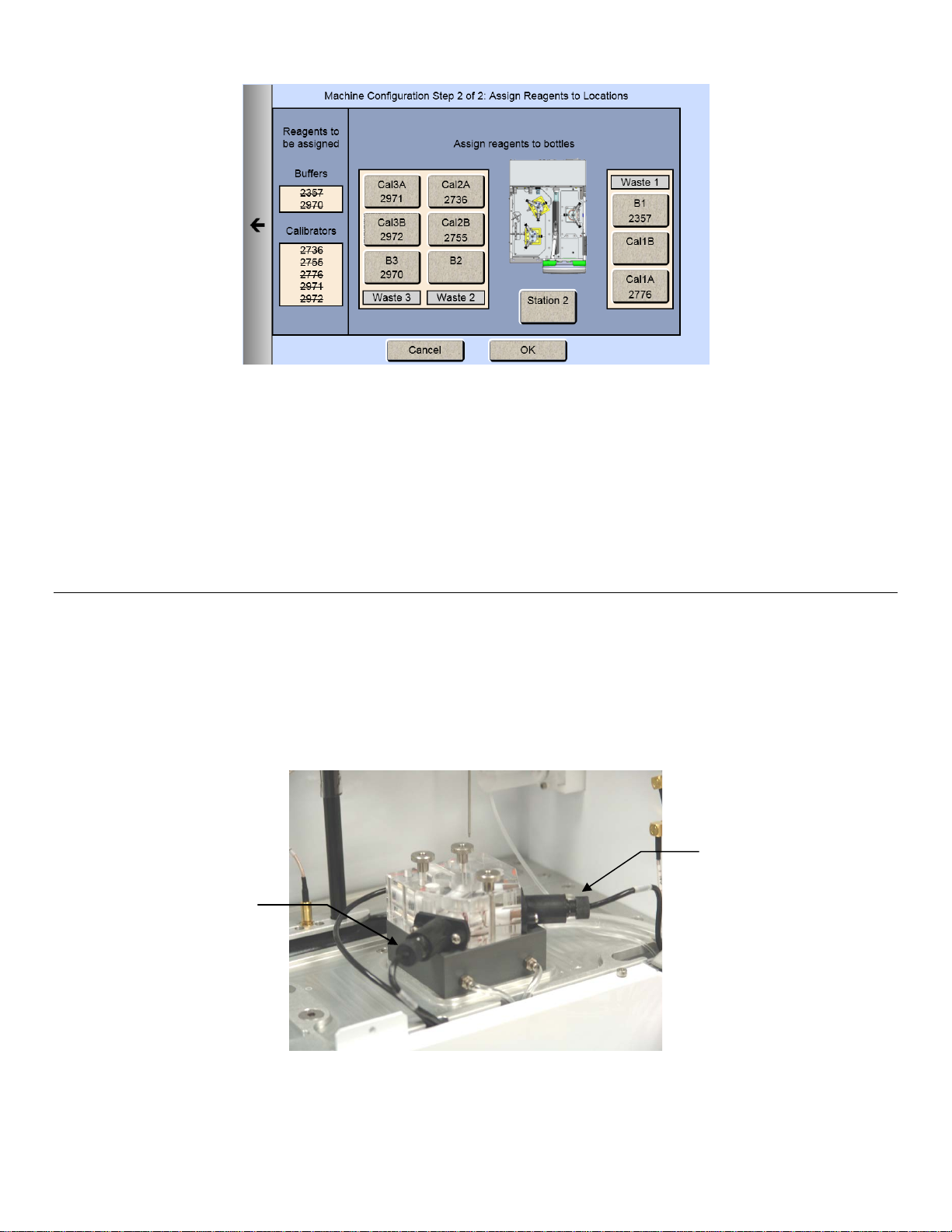
Calibration Pumping System Maintenance ..................................................................... 120
9.3.1
Preventive Maintenance – 6 months or 1000 Hours ............................................................. 121 9.4
Sample Module Cleaning ................................................................................................ 121
9.4.1
9.4.2 Waste Module Cleaning .................................................................................................. 122
9.4.3 Enzyme Probe Cleaning ................................................................................................. 122
9.4.4 ISE Cleaning ................................................................................................................... 123
9.4.5 Sipper pump Seal Replacement ..................................................................................... 123
9.4.6 Bottle Tubing ................................................................................................................... 125
9.4.7 Pump Tubing Replacement ............................................................................................ 127
9.4.8 Install Waste Modules ..................................................................................................... 130
9.4.9 Waste Tubing .................................................................................................................. 130
9.4.10 Install Sample Modules ............................................................................................ 131
9.4.11 Sipper Replacement ................................................................................................. 131
9.4.12 Calibrate Sipper ........................................................................................................ 132
9.4.13 Install Bottles ............................................................................................................ 132
9.4.14 Install Membranes and ISEs..................................................................................... 132
9.4.15 Prime Fluid System .................................................................................................. 132
3

Fuse Replacement................................................................................................................. 133 9.5
Fuse Requirements ......................................................................................................... 133
9.5.1
2960 Maintenance ................................................................................................................. 133 9.6
Tubing Replacement ....................................................................................................... 133
9.6.1
9.6.2 Monitor Sample Cup ....................................................................................................... 135
10. Storage ........................................................................................................................................ 136
Instrument Storage ................................................................................................................ 136 10.1
Enzyme Membrane Storage .................................................................................................. 136 10.2
ISE Storage ........................................................................................................................... 136 10.3
Reference ISE .......................................................................................................... 136
10.3.1
10.3.2 Ammonium/Potassium ISE ....................................................................................... 136
Instrument Handling/Transport .............................................................................................. 136 10.4
Troubleshooting ......................................................................................................................... 136
11.
Printout Information ............................................................................................................... 138 11.1
Enzyme Sensors ...................................................................................................... 138
11.1.1
11.1.2 Ion Selective Electr odes ........................................................................................... 140
Troubleshooting Chart ........................................................................................................... 143 11.2
2960 Online Monitor ................................................................................................. 147
11.2.1
12. Principles of Operation .............................................................................................................. 149
Enzyme Sensor Technology .................................................................................................. 149 12.1
Ion Selective Electrode .......................................................................................................... 150 12.2
Measurement Methodology ................................................................................................... 150 12.3
Baseline Stability ................................................................................................................... 151 12.4
Calibration .............................................................................................................................. 151 12.5
Linearity ................................................................................................................................. 151 12.6
Temperature Compensation .................................................................................................. 152 12.7
Level Sensing ........................................................................................................................ 152 12.8
Warranty and Repair .................................................................................................................. 152
13.
Limitation of Warranty ............................................................................................................ 152 13.1
Shipping Instructions ................................................................................................ 152
13.1.1
13.1.2 Cleaning Instructions ................................................................................................ 153
YSI Factory Authorized Service C ent ers ............................................................................... 154 13.2
Notices ........................................................................................................................................ 155
14.
Declaration of Conformity ...................................................................................................... 155 14.1
Declaration of Conformity - Australian and New Zealand Electromagnetic Compatibility .... 156 14.2
Radio and Television Interference Notice ............................................................................. 157 14.3
Appendix A – Software Flowchart ............................................................................................ 158
15.
16. Appendix B – Concentration Unit Conversion ........................................................................ 159
Linearity Test. Concentration Unit Conversion ...................................................................... 160 16.1
FCN Membrane Integrity Test. Concentration Unit Conversion ............................................ 161 16.2
Appendix C - Line Power Cord and Plug Wiring ..................................................................... 162
17.
18. Appendix D - Reagents and Accessori es ................................................................................ 163
4

1. Introduction
Ammonium
D-Glucose (Dextrose)
Potassium
Hydrogen Peroxide1
L-Lactate
Sucrose
L-Glutamate
Ethanol
L-Glutamine
Glycerol
Ethanol-HC
Methanol
Xylose
Galactose1
Choline
Lactose
Slim modular design
Easily expand analytes or chemistries
Proprietary enzyme electrode
Fast, accurate, and analyte-specific results
Uses biological separation technology
No hazardous chromatography solvents to dispose
Icon-driven user interface with touchscreen
Easy to learn
Data download options
Save data on a USB drive, send it over the network,
Onboard training videos
Minimizes operator learning curve
21 CFR Part 11
Regulatory compliance
Description 1.1
The 2900 Series Biochemistry Analyzer is a laboratory instrument intended for use in research, food-processing and
bioprocessing applicati ons . THE 2900 Series IS NOT FOR HUMAN MEDICAL DIAGNOSTIC USE OR FOR HUMAN
PERFORMANC E EVALUATION.
The 2900 Series can be set up to measure up to 6 different analytes in a sample. The total number of analytes depends
on the number of sample modules installed (up to two analytes per module) and the number of different buffers required
(up to three buffers). Available analytes are listed below.
Additional analytes are currently under development. For a current listing, please contact YSI Life Sciences Technical
Support (937 767-2769 or 800 659-8895 extension 2) or visit the YSI Life Sciences web site at www.ysi.com
/lifesciences.
User Features 1.2
Multiple units use much less bench space
of
or access it in a searchable database anytime
Models 1.3
• 2900D 2900 Biochemistry Analyzer with 1 biosensor module
• 2900M 2900 Online Monitor & Control System
• 2950D-0 2950 Biochemistry Analyzer with 1 biosensor module
• 2950D-1 2950 Biochemistry Analyzer with 2 biosensor modules
• 2950D-2 2950 Biochemistry Analyzer with 3 biosensor modules
• 2950D-3 2950 Biochemistry Analyzer with 2 biosensor modules and 1 ISE module
• 2950D-4 2950 Biochemistry Analyzer with 1 biosensor module and 1 ISE module
1
YSI does not currently offer calibration standards for this analyte.
5

2900 Series General Specifications 1.4
Sample size ................................................. Adj us table f rom 10 to 50 m icr oliters ( as pirated volume), per module
Response time ............................................ Enzyme Sensors
• Sample results in 60 seconds ( average) for one module
• 100 seconds for 2 modules
• 135 seconds for 3 modules
• Complete sample-to-sample cycle in less than 3 minutes
(May vary with analyte and sample m atr ix.)
Ion Selective Electrodes (ISE)
• Sample results in 150 seconds (aver age) f or 2 modules
• 195 seconds for 3 modules
• Complete sample-to-sample cycle in less than 5 minutes
(May vary with analyte and sample m atr ix)
Output signals:
Serial .......................................................... USB and RS232
Power requirement ............................... 100–240 VAC ±10%
50–60 Hz ±5%
42 Watts nominal
Working environment:
Ambient temperature ................................ 15–35°C
Relative humidity ...................................... 10–75% (non-condensing)
Regulatory compliance .................................. ETL, CE, RoHS
61010-1 compliance:
• Pollution degree 2
• Installation category 2
• Altitude 2000m
• Atmosphere 75 KPa to 106 KPa
• Indoor use only
Instrument dimensions ................................ 14.0" wide x 20.5" deep x 15.75" h igh
35.6 cm x 52.1 cm x 40.0 cm
Instrument weight ........................................ 39 pounds
17.7 kilograms
2960 Online Monitor Specifications 1.5
1.5.1 Monitor
Size:
Monitor Cup ............................................... 0.75 x 0.75 x 0.88 inches
Pump Head ................................................ 2.0 x 2.2 x 0.85 inches
Sample Inlet Tubing ...................................... Silicone, 0.08 OD x 0.02 ID (inches)
Volume ....................................................... 5.1 microliters/inch
Inlet Channel Pump Tubing ........................... PharMed
, 0.13 OD x 0.035 ID (inches)
6

Valve Tubing ................................................. 0.03 ID (inches)
Wasteline Tubing .......................................... Silicone, 0.16 OD x 0.10 ID (inches)
Nominal Flow Rate (inlet line) ....................... 100–2500 microliters/minute (± 8% @ ± 6 PSI)
1.5.2 Analog/Control
Full Scale Voltage ......................................... Selectable: +10.00 VDC or +5.00 VDC
Full Scale Concentration ............................... User selectable
Resolution ..................................................... 1:65,536 or 0.0015% FS,
0.153 mv on +10.00 VFS,
0.076 mv on +5.00 VFS
Maximum Gain Error ..................................... ±12 LSB
Linearity ......................................................... ±1 LSB
Minimum analog output Load Impedance ..... 2K Ohms
Logic output drive .......................................... 0 and 5 VDC nominal at 10 milliamps
Logic Input levels .......................................... < 0.8 VDC = logic 0,
...................................................................... > 2.0 VDC = logic 1
2. Safety
Important Safety Instructions 2.1
DO NOT PLUG THE INSTRUMENT IN AT THIS TIME. You should apply power only when directed to do so in the setup
instructions.
1. Use ONLY the line power cord supplied with the instrument. When directed to, connect the plug to a matching threepronged wall receptacle.
2. Use ONLY fuses of the type supplied. Replacement power cords and fuses can be obtained from YSI, or your Dealer
Representative.
3. Do NOT use an extension cord without protective grounding.
4. Do NOT remove rear cover. There are no user serviceable parts inside.
5. Repairs are to be performed only by trained and approved personnel.
6. This instrument must be connected to a protectively grounded (earthed) outlet.
7. The following notice is provided in compliance with IEC1010 Part 1 1990.
See Appendix for mains plug wiring and fusing instructions.
8. If the equipment is used in a manner not specified by YSI, the protection provided by the equipment may be impaired.
WARNING: For RS232 or USB connection, equipment should be EN/CSA/UL 61010 or EN/CSA/UL 60950
approved only.
9. The mains (power) switch is for functional purposes ONLY. To disconnect the instrument from the mains supply,
unplug the mains power cord from the back of the instrument.
10. Personal protective equipment (PPE) recommended—protective gloves and safety goggles or glasses.
7
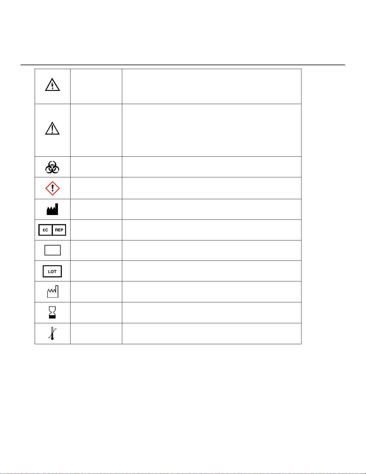
Warning indicates that misuse of the instrument could result in
Caution, consult accompanying documents. Caution indicates
Biological Risks
Chemical Irritant
Manufacturer
Authorized Representative in the European Union
Catalog number
Lot number
Date of manufacture
Use by Date
Temperature Limitation
REF
Explanation of Symbols 2.2
WARNING
AVERTISSEMENT
CAUTION
ATTENTION
2776
death or serious injury to a person.
Un avertissement indique qu'une mauvaise utilisation de l'instrument
peut entraîner la mort ou une blessure grave chez une personne.
that misuse of the instrument could result in mild or serious injury
to a person and/or damage to equipment.
Attention, consulter la documentation jointe. Cette mise en garde
indique qu'une mauvaise utilisation de l'instrument peut entraîner une
blessure légère ou grave chez une personne et/ou un endommagement
du matériel.
Risques biologiques
Irritant chimique
Fabricant
Représentant agréé dans l'Union européenne
Numéro de référence
15A100549
Numéro de lot
YEAR-MO
Date de fabrication
YEAR-MO
Date limite d'utilisation
Limite de température
8
3. Getting Started
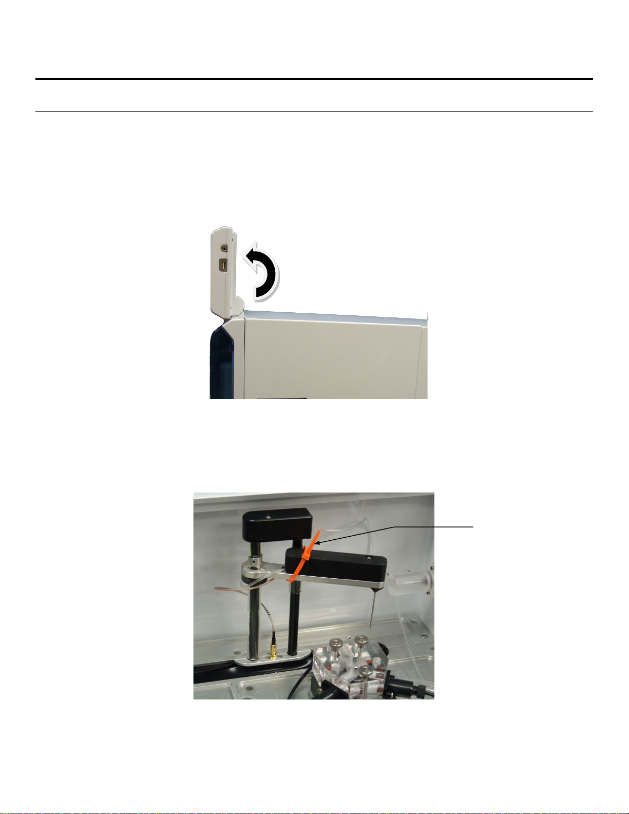
Remove tie strap
Unpacking 3.1
When you unpack your new 2900 Series for the first time, check the packing list to make sure you have received
everything listed. Note that reagents for the 2900 Series are not packaged in the same carton as the instrument. If there is
anything missing or damaged, call the dealer from whom you purchased the 2900 Series. If you do not know which of our
authorized dealers sold the system to you, call YSI Life Sciences Customer Service at 800 659-8895 or 937 767-7241,
and we'll be happy to help you.
1. After removing the instrument from the shipping box, tilt the display to the full upright position.
Figure 3.1
2. Grasp the hand hold in the right side cover of the instrument and pull up and out to remove the cover.
NOTE: Leave the cover off the instrument until you have aligned the sipper and installed the membranes as
described in the following sections.
3. Carefully cut the tie strap holding the sipper.
Figure 3.2
9
Warranty Card 3.2
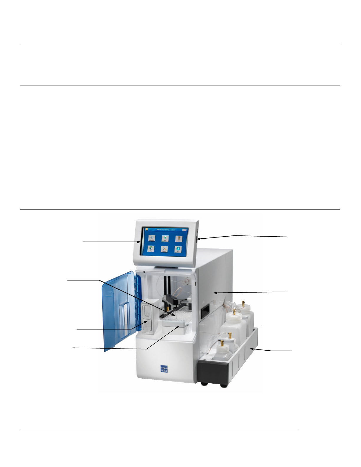
Cover
Sipper
Display/
Touch Panel
USB Port
Station 2
Bottle Rack
Station 1
Please complete the Warranty Card and return it to YSI. This will record your purchase of this instrument in our computer
system. Once your purchase is recorded, you will receive prompt, efficient service in the event any part of your 2900
Series should ever need repair.
What You Need 3.3
Several things are needed in order to analyze samples using the 2900 Series. The following list shows the basic items
required.
• 2900 Series Instrument (with AC Power Cord)
• Bottle Racks wi th Reagent Level Sensing (YSI 2936, 2938), or Bottles without Reagent Level Sensing (YSI
2934, 2937)
• YSI Buffer(s)
• YSI Calibrator Standard(s)
• YSI Linearity Standard(s )
• YSI Membrane(s)
• YSI ISE probes (2950D-3 and 2950D-4 models only)
• YSI 2960 Online Monitor (optional)
• YSI 2901 Printer (optional)
Major Components 3.4
Display
Figure 3.3
Graphical color LCD covered by a touc h s cr een
10
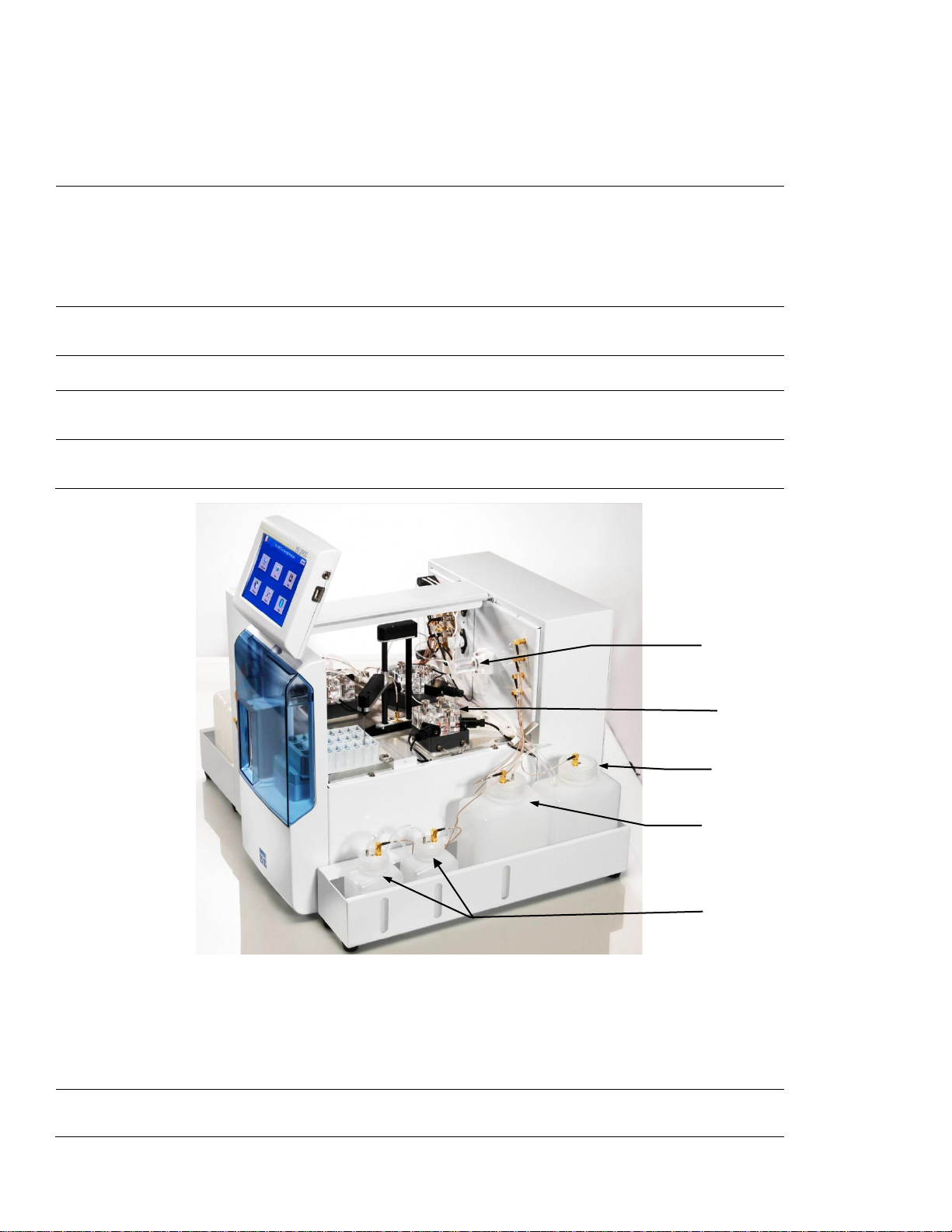
USB ports
Sample Module
Sipper Pump
Waste Bottle
Buffer Bottle
Calibrator Bottles
The USB ports allow a flash drive to be con nected to the 2900
Series to download sample results or upgrade the ins trument’s
software. A USB port is located on the right s ide of the dis play. An
additional USB port is located on the rear of the ins trum ent . T he rear
port is used to connect the 2960 Online Monitor to the 2900 Series.
Sipper
Station 1
Station 2
Buffer Pumps
(not shown)
Calibrator Pumps
(not shown)
Can be raised, lowered, rotated, and moved horizontally to its
various positions.
The positions are: Calibrator W ells, Sam ple Module, Stations 1 an d
2, and Monitor Sample Cup.
The Sipper senses fluid level to control immersion depth and detect
errors.
Plate and rack holder accepts mos t standard plates /racks for batch
sampling of up to 96 samples.
Test tube holder for manual sampling.
Draw buffer from the buffer bottles, pump it through the Valves,
Sipper Pump and the Sipper, and flus h the Sample Module.
Draw the appropriate standard s olution f rom the C alibrator Bottles
and fill the Calibrator Wells.
Sipper pump
Sample modules
Figure 3.4
It retracts its piston to draw standar d f rom the Calibrator Wells or
sample from the sample stations.
It extends its piston to dispense standard or sample into the sample
module.
They are made of clear acrylic plastic . Sensor probes are screwed
into either side of the module.
11
In biosensor modules, the imm obilized enz yme membranes are
mounted on O-rings which act as fluid s eals.
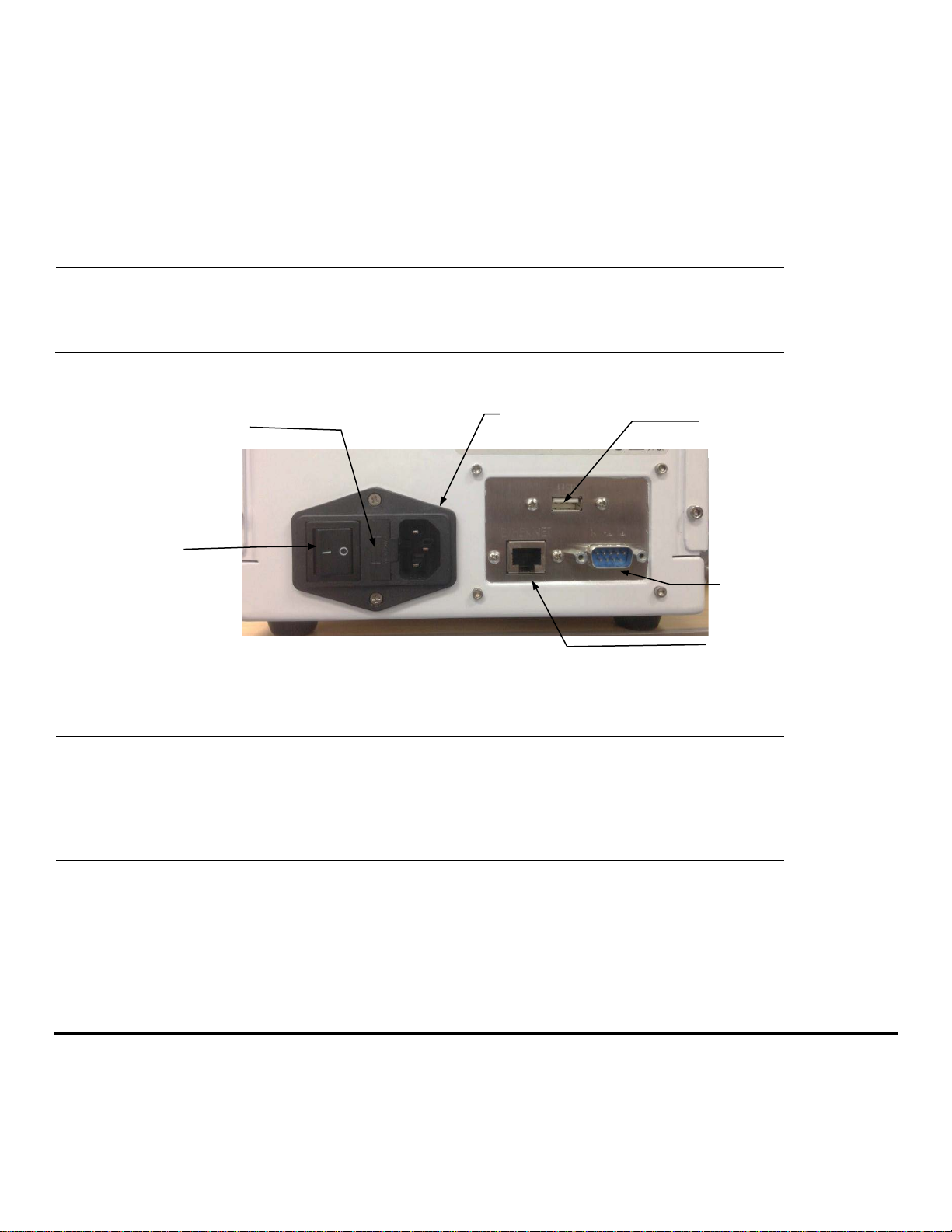
Power
Receptacle
RS232 Port
Power Switch
Fuse
Holder
Ethernet Port
USB Port
In ISE modules, an O-ring is pos itioned insid e a sleev e on the end of
the electrode.
A reference or auxiliary electrode is housed in the temperature probe
and positioned at the back of the Sam ple m odule.
Stir Bars
(not shown)
Buffer, Waste and
Calibrator Bottles
Power Switch
They are plastic encapsulat ed magnets. They are activated by
motors housed below the sample m odules. They provide thorough
mixing inside the sample modules.
Are conveniently located for m aintenanc e.
Fluid levels are monitored by sensors .
Operation is automatically halted when the B uf fer or Calibrator
Bottles are empty, or when the W aste bott les ar e full.
Rear Panel
Figure 3.5
The main power switch is an on/off rock er switch ( 0-off and I-on)
located on the back of the instrument
Fuse Holder
Power Receptacle
Ethernet Port
RS232 Serial Port
The fuse holder houses the power line fus e and ope n s up f or fuse
replacement.
One end of the power cord (supplied) plugs into t his rec eptac le,
while the other end plugs into a properl y grounded e l ect ric al outlet.
The instrument will automatically adj ust the voltage as needed.
It allows connection to a network or r outer via a RJ 45 Ethernet por t.
The RS232 connection is a standard D B9F c onnect or. It is used to
interface with the YSI 2901 Printer or a r em ote hos t.
4. Basic Setu p
The following list describes the basic steps necessary for sampling with the 2900 Series.
1. Install Bottle Racks
2. Connect Printer (optional)
3. Connect AC Power
12
4. Connect 2960 Online Monitor (optional)
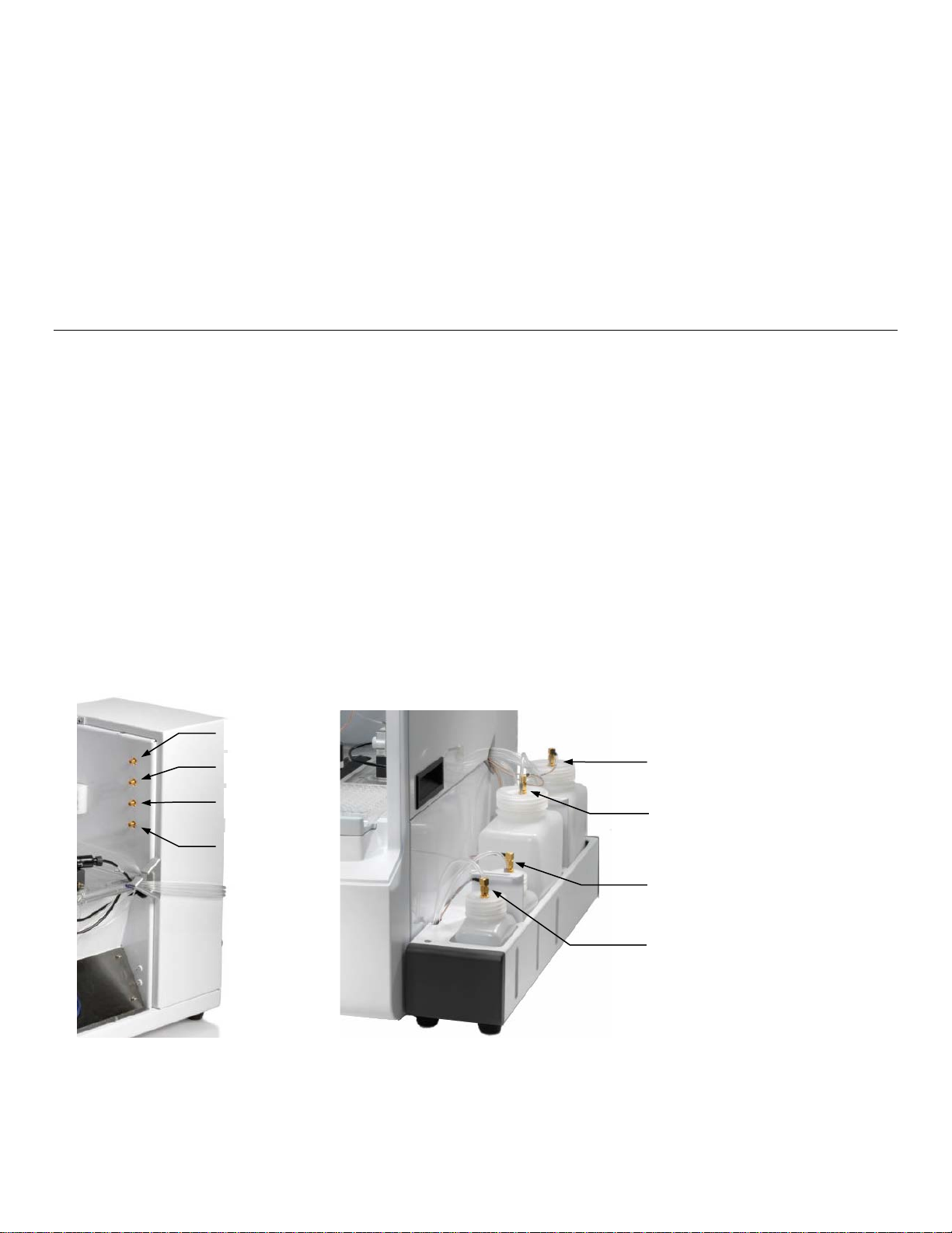
Buffer Bottle 1
Waste Bottle
Calibrator Bottle
CAL 1B
Waste 1
Buffer 1
CAL 1A
CAL 1B
Calibrator Bottle
5. Align Sipper
6. Configure Instrument Chemistries
7. Prepare and Install Buffer solution(s)
8. Install Calibrator Solution(s)
9. Install Membrane(s) and ISEs
10. Prime the Fluid System
11. Check Probe Currents
Install Bottle Racks 4.1
4.1.1 Right Side
1. Install the YSI 2938 Bottle Rack with Reagent Level Sensing onto the right side of the instrument by sliding the
slots in the tray over the pins on the side of the instrument.
If you are not using the reagent level sensing option, place the YSI 2934 Bottles on the right side of the
instrument.
2. Then remove the packing material holding the tubing to the right side of the instrument.
3. Next, connect bottle tubing and cables
a. Insert the large diameter waste tube into the hole in waste bottle 1.
b. Connect one end of a short cable marked to the threaded fitting on the waste bottle 1 cap and connect
the other end to the Waste 1 (top) fitting on the instrument.
c. Connect the tubing marked “B1” and one end of a short cable to the fittings on the buffer bottle 1 cap and
connect the other end of the cable to the Buffer 1 (2nd) fitting on the instrument.
d. Connect the tubing marked “C1B” and one end of a long cable to the fittings on the second calibrator
bottle cap and connect the other end of the cable to the CAL 1B (3rd) fitting on the instrument.
e. Connect the tubing marked “C1A” and one end of a long cable to the fittings on the first calibrator bottle
cap and connect the other end of the cable to the CAL 1A (bottom) fitting on the instrument.
CAL 1A
Figure 4.1
13

4.1.2 Left Side (2950 models only)
Buffer Bottle 2
Waste Bottle 3
Waste Bottle 2
Calibrator Bottle
Buffer Bottle 3
Calibrator Bottle
1. Install the YSI 2936 Bottle Rack with Reagent Level Sensing onto the left side of the instrument by sliding the
slots in the tray over the pins on the side of the instrument.
2. If you are not using the reagent level sensing option, place the YSI 2937 Bottles on the left side of the instrument.
3. Then remove the packing material holding the tubing to the left side of the instrument.
4. Next, connect bottle tubing and cables
a. Insert the large diameter waste tubing into the holes in waste bottles 2 and 3.
b. Connect one end of a long cable to the threaded fitting on the waste bottle 2 cap and connect the other
end to the W2 (top left) fitting on the instrument.
c. Connect one end of a long cable to the threaded fitting on the waste bottle 3 cap and connect the other
end to the W3 (top right) fitting on the instrument.
d. Connect the tubing marked “B2” and one end of a long cable to the fittings on the buffer 2 bottle cap and
connect the other end of the cable to the B2 (2
e. Connect the tubing marked “B3” and one end of a long cable to the fittings on the buffer 3 bottle cap and
connect the other end of the cable to the B3 (2
nd
from top on left) fitting on the instrument.
nd
from top on right) fitting on the instrument.
f. Connect the tubing marked “C2A” and one end of a short cable to the fittings on the calibrator 2A bottle
cap and connect the other end of the cable to the 2A (bottom left) fitting on the instrument.
g. Connect the tubing marked “C2B” and one end of a short cable to the fittings on the calibrator 2B bottle
cap and connect the other end of the cable to the 2B (3
rd
from top on left) fitting on the instrument.
h. Connect the tubing marked “C3A” and one end of a short cable to the fittings on the calibrator 3A bottle
cap and connect the other end of the cable to the 3A (bottom right) fitting on the instrument.
i. Connect the tubing marked “C3B” and one end of a short cable to the fittings on the calibrator 3B bottle
cap and connect the other end of the cable to the 3B (3
rd
from top on right) fitting on the instrument.
CAL 2A
CAL 3A
Figure 4.2
14
Connect Printer 4.2
Connect the YSI 2901 Printer to the 2900 Series Biochemistry Analyzer using the data cable provided. The small RJ12
connector plugs into the bottom of the printer and the large DB9 connector plugs into the RS232 port on the back of the
analyzer. Refer to the instruction sheet included with the printer for details of printer operation.
Connect AC Power 4.3
1. Plug the power cord (included with the 2900 Series Analyzer) into the power receptacle on the back of the
instrument, then into a properly grounded electrical outlet provided with a 15 or 20 Amp circuit breaker. The
instrument will automatically adjust the voltage as needed.
If you are located outside the United States, see Appendix for Line Power Cord and Plug Wiring.
WARNING: Keep your hands clear of the sipper while the instrument is in operation.
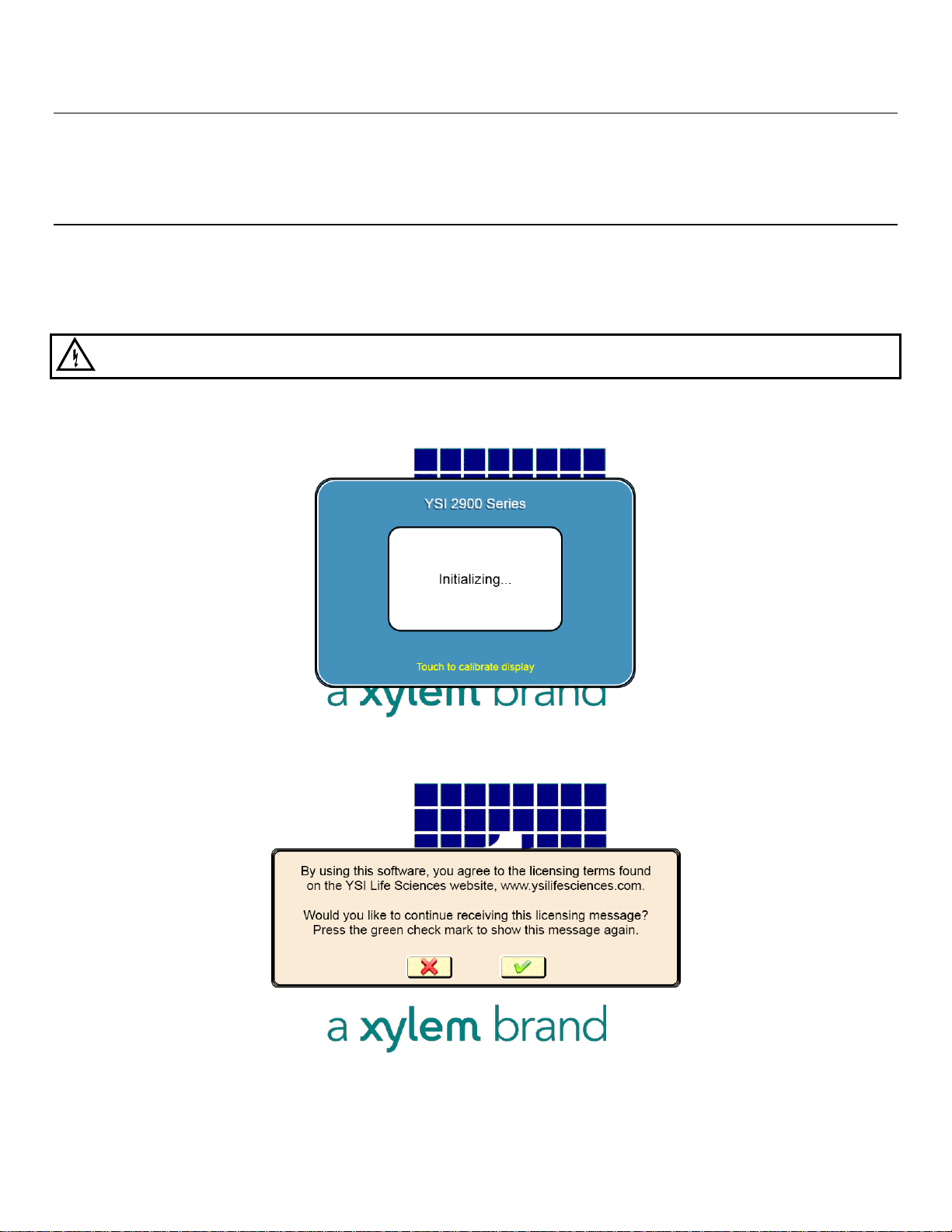
2. Turn the instrument on with the main power switch on the rear panel. After about 30 seconds, the Initializing
window should appear.
3. The first time the instrument is powered up, the software license window will appear. Touch [X] to prevent the
license screen from appearing each time the instrument is turned on.
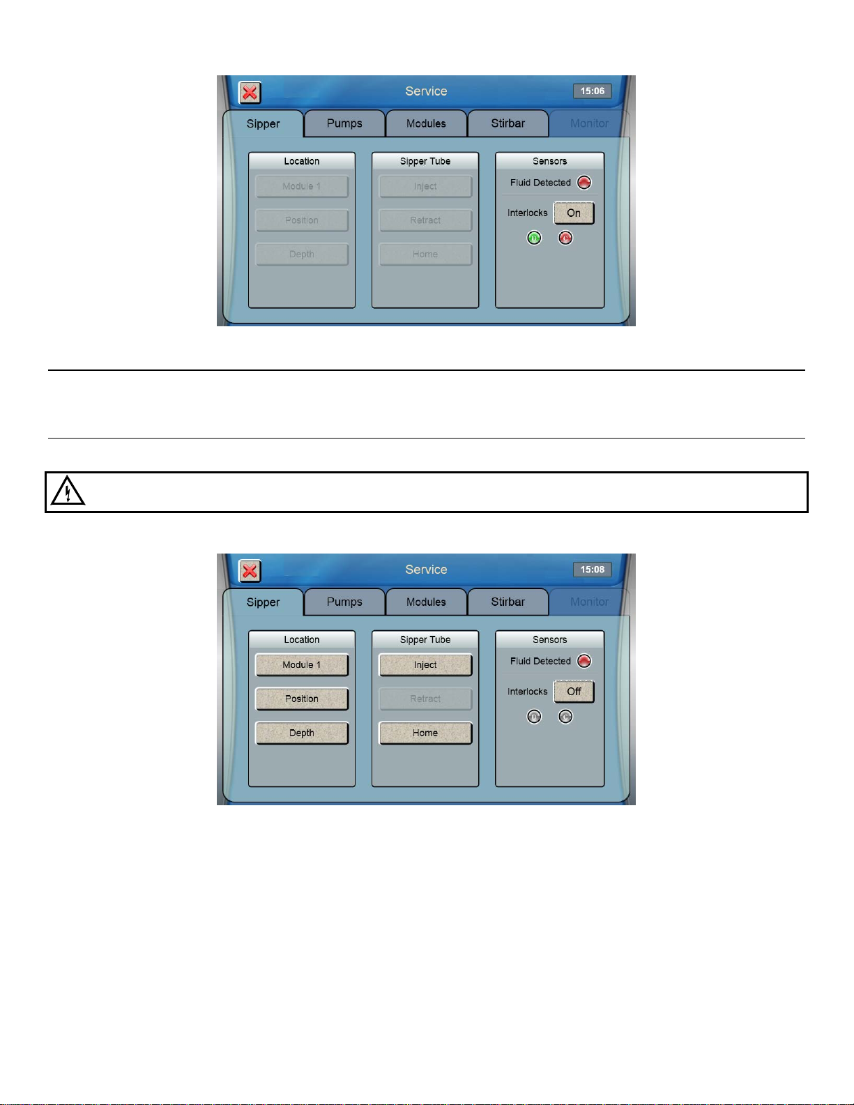
4. Since the top cover of the instrument is removed, the Service screen will appear. Touch the Interlock [On] button
and change it to [Off] to disable the safety interlock, and then press to confirm.
15
Connect 2960 Online Monitor 4.4
If you will be using the 2960 Online Monitor, see Section 6.1 for instructions on how to connect it.
Align Sipper 4.5
It is very important that the sipper be accurately adjusted.
WARNING: Keep your hands clear of the sipper while the instrument is in operation.
1. From the Sipper tab of the Service screen, touch [Module 1].
2. The Select Location screen will appear. Select [Module 1]. The sipper will move to sample module 1 and should
be centered above the cone shaped opening in the top of the module.
If the sipper does not move, make sure the packing material was removed.
16
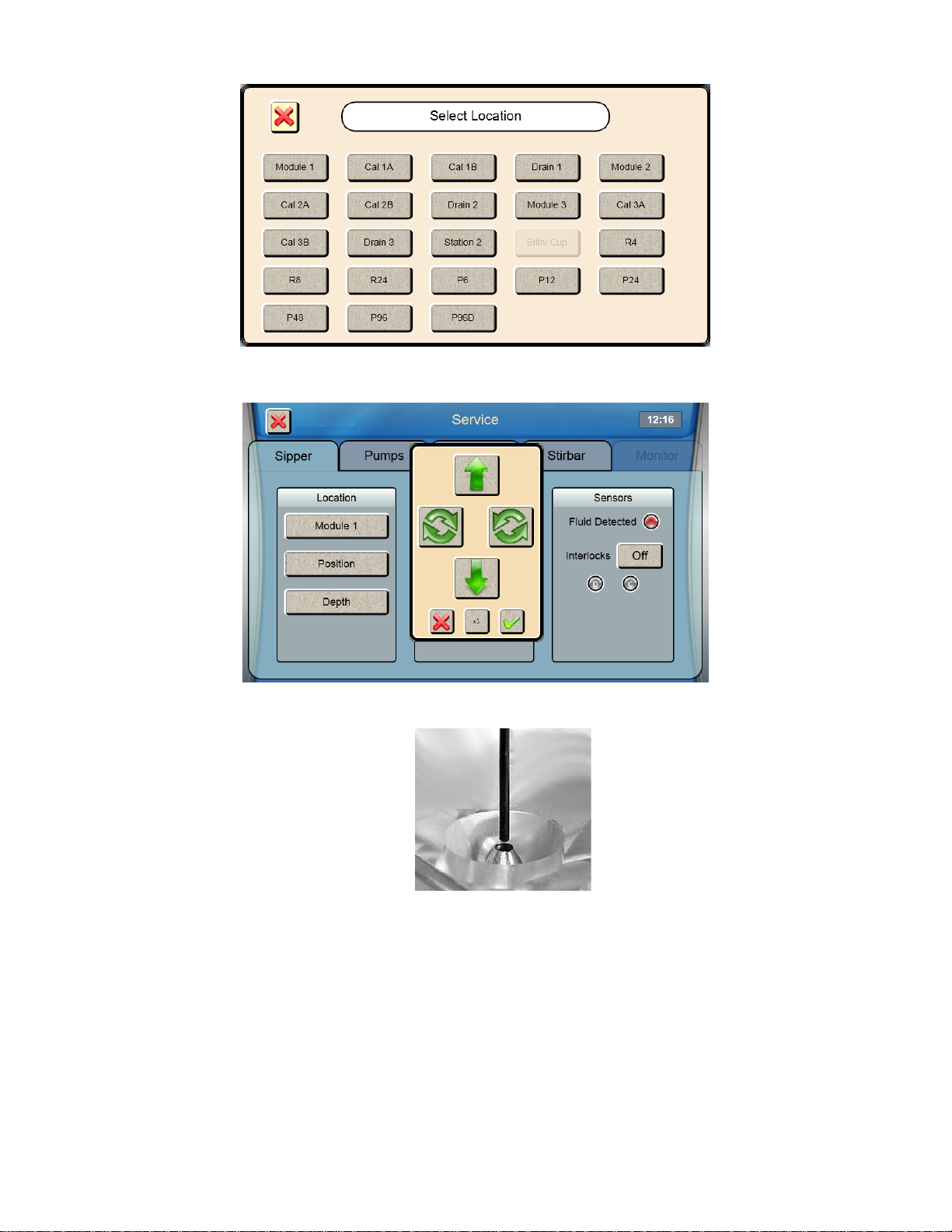
3. If the sipper is not centered, touch [Position] and use the arrow buttons to center the sipper.
4. Make certain the Sipper is centered, then touch at the bottom right of the adjustment window.
Sipper Adjustment Position
Figure 4.3
5. Touch to save the position and close the confirmation window.
6. To test the alignment of the sipper, Touch [Inject] to lower the sipper, then touch [Retract] to raise the sipper back
up.
If necessary, touch [Position] and repeat the adjustment.
17
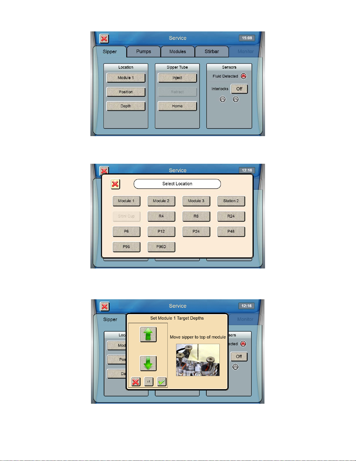
7. Once the sipper enters the sample module without hitting the cone, touch [Depth] to set the sipper depth. The
Select Location screen will appear.
8. Select [Module 1]. The tip of the sipper should be right at the top of the module. Use the arrow buttons to lower or
raise the sipper until the tip of the sipper is even with the top of the module.
9. Then touch at the bottom right of the adjustment window.
10. Touch to save the depth and close the confirmation window.
11. Check the sipper alignment at the Cal 1A, Cal 1B and Drain 1 locations and adjust the position if necessary.
18

12. Once you have aligned the sipper and properly set the depth, sipper alignment for Module 1 is complete. Touch
[X] at the top left of the screen to return to the main display.
Repeat this procedure for any additi on al modules installed on your 2950 analyzer.
After you have aligned the sipper with all installed modules, touch the Interlock button and change it back to [On]
to enable the safety interlocks.
Configure Instrument Chemistries 4.6
Before operating the 2900 Series, you must set the instrument parameters.
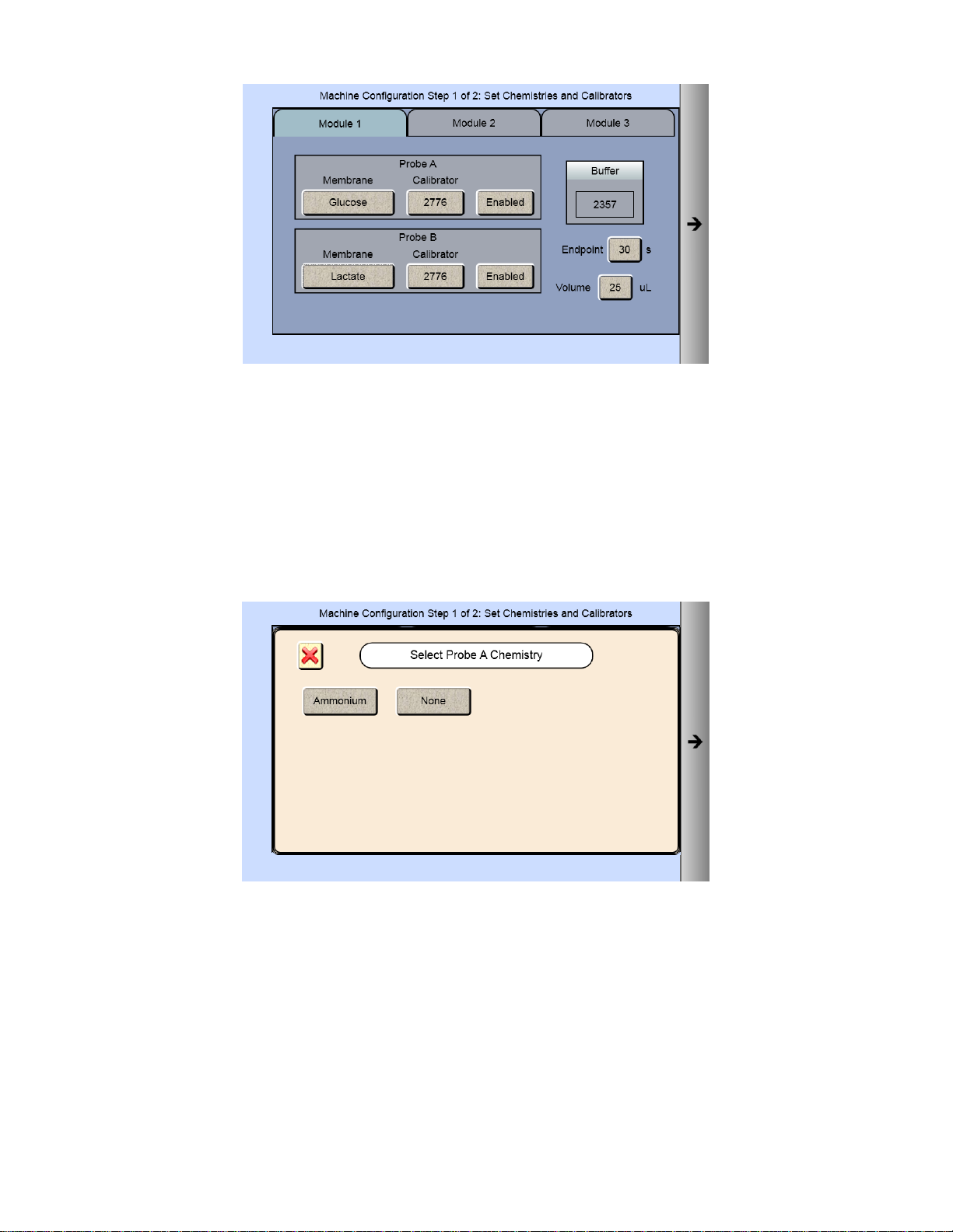
4.6.1 Assign Chemistries to Probes
1. From the main display, touch
2. From the [Module 1] tab, touch the Probe A membrane button.
.
3. Select the chemistry you want to measure
19
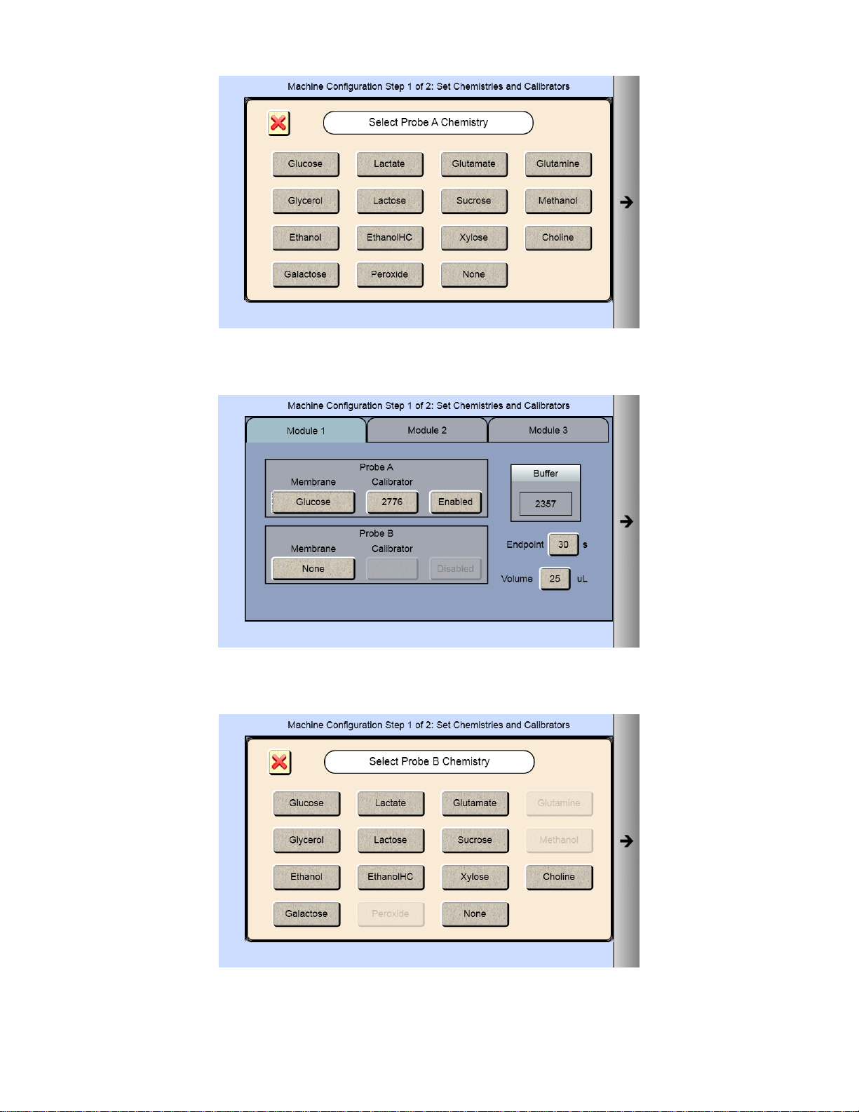
4. The Probe A Membrane button will now show the chemistry you have selected. The screen also indicates which
reagents should be installed.
5. To run a second chemistry in module 1, touch the Probe B membrane button. Only chemistries that can be run
simultaneously with your selected chemistry will be displayed.
6. Select the chemistry you want to measure. The Probe B Membrane button will now show the chemistry you have
selected.
20
NOTE: The default Sample Volume and Endpoint for the chemistries are also displayed. Use the default settings unless
a particular application instruction specifies another value (see Section 8 Chemistry Setup for details).
7. Once you have selected one or two chemistries for the first module, proceed to the next installed module on your
instrument, and repeat the procedure.
NOTE: Changing chemistry assignments will change the calibrator values back to the default settings.
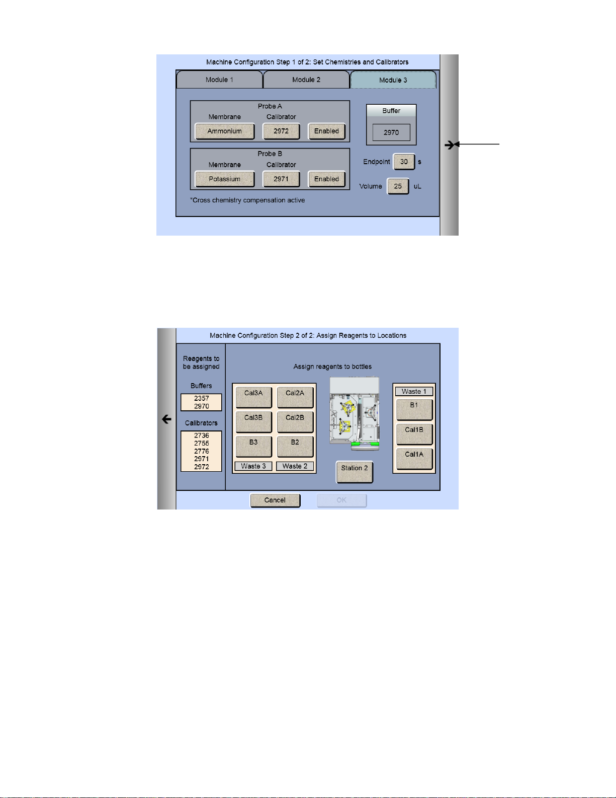
If your instrument has an ISE module:
1. From the [Module 3] tab, touch the Probe A membrane button and select Ammonium.
2. The Probe A Membrane button will now show the chemistry you have selected.
Potassium will automatically be selected for Probe B.
21
Next Arrow
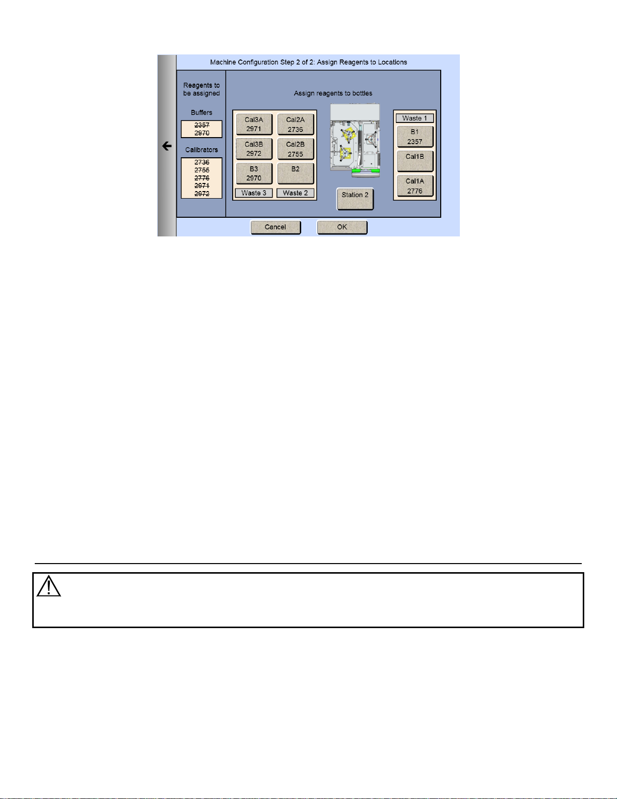
4.6.2 Assign Reagents
Once you have selected all the chemistries you want to measure, touch the Next arrow on the right of the screen. The
Assign Reagents screen will be displayed.
Reagents needed are listed on the left of the screen. Bottle positions are listed on the right. Each reagent must be
assigned to a bottle position.
4.6.2.1 Buffers
1. Touch the [B1] button to display the Select Buffer screen.
22
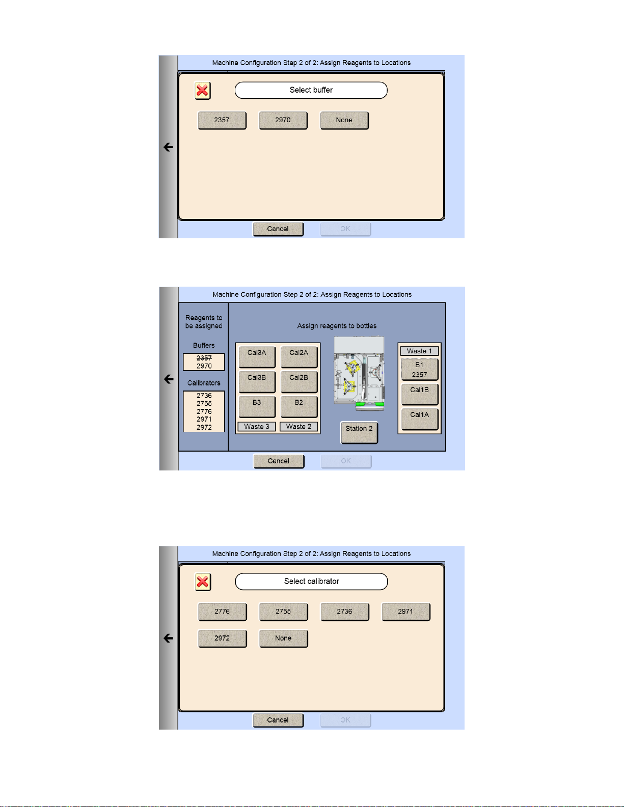
2. Pick your appropriate buffer and it will be assigned to the B1 button.
Note that the selected buffer is now marked out in the list of reagents needed.
3. For additional buffer assignment, please repeat process.
4.6.2.2 Calibrators
1. Touch the [Cal 1A] button. The Select Calibrator screen appears.
23
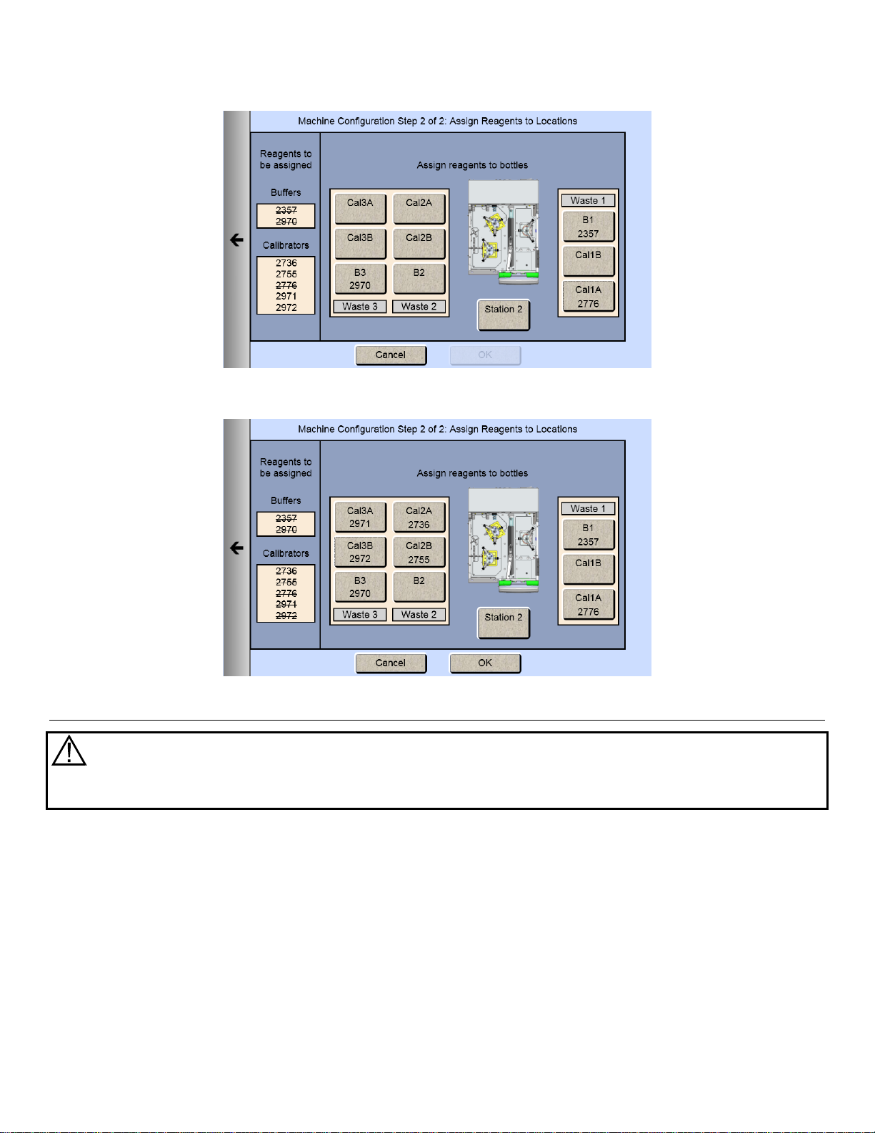
2. Pick the appropriate calibrator.
3. Select additional bottles until all reagents on the left side of the screen have been assigned and marked out.
Prepare and Install Buffer Solutions 4.7
Caution: To prevent possible damage due to an electrostatic discharge, do NOT touch the metal
tips of the connectors located at the ends of the bottle leads. Handle only the insulated section of
the connectors.
Prepare the system buffers and fill the buffer bottles as indicated on the display.
24
4.7.1 Prepare Buffer
4.7.1.1 From powder concentrate:
1. Place about 500 mL of reagent water (distilled or deionized) into a 1000 mL flask or other clean container.
2. Add two packages of powder buffer concentrate and stir.
3. Add more reagent water until the total volume of solution is between 900 and 1000 mL.
4. Stir as necessary until the buffer chemicals have completely dissolved.
4.7.1.2 From liquid concentrate:
Mix the content of the bottle of liquid buffer concentrate with enough reagent water (distilled or deionized) to make
1000 mL.
4.7.2 Install Buffer Solution(s)
Unscrew and remove the lid from one of the buffer bottles.
IMPORTANT: When adding fresh buffer to the Buffer Supply Bottles, m ak e every effort to avoid contamination of
the lid and level sensor assemblies.
Pour the prepared buffer into the buffer bottle.
Install the bottle in the rack as indicated on the dis play.
Replace the bottle lid.
Install Calibrator Solution(s) 4.8
Caution: To prevent possible damage due to an electrostatic discharge, do NOT touch the metal
tips of the connectors located at the ends of the bottle leads. Handle only the insulated section of
the connectors.
25
Probe B
Probe A
Unscrew and remove the lid from the empty calibrator bottle (Cal1A–Cal3B as indicated).
IMPORTANT: make every effort to avoid contamination of the lid and level sensor as s emblies.
Mark the date of installation on the label of the ne w bot tle of YSI calibrator soluti on.
Place the new bottle of calibrator in the bottle rack as indicated on the display.
Screw the lid and level sensor assem bl y onto it.
Repeat this process for any additional c alibrator bot tles ( Cal1A–Cal3B as indicated).
Install Membranes and ISEs 4.9
4.9.1 Enzyme Membranes
Each biosensor probe installed in your instrument is fitted with a protective "shipping membrane" which must be removed
and replaced with a new membrane. Make sure you install the correct membrane for each chemistry you are
measuring.
Enzyme membranes are color-coded for each type of chemistry. It is important that you install the specific membrane as
indicated on each probe (A or B).
.
Probe A is always on the left when looking in from the side of the instrument
Figure 4.4
26
To install a membrane:
1. Make sure the top cover(s) are removed from the instrument.
2. Next, unscrew the appropriate enzyme probe retainer and gently pull the probe out of the module.
3. Remove the existing O-ring membrane assembly from the end of the enzyme probe. A lint free tissue or toothpick
or pipet tip may be needed to unseat the old membrane. Be careful not to scratch the enzyme probe face.
4. Examine the enzyme probe surface and remove any pieces of membrane that remained.
5. Open a cavity of the plastic membrane holder.
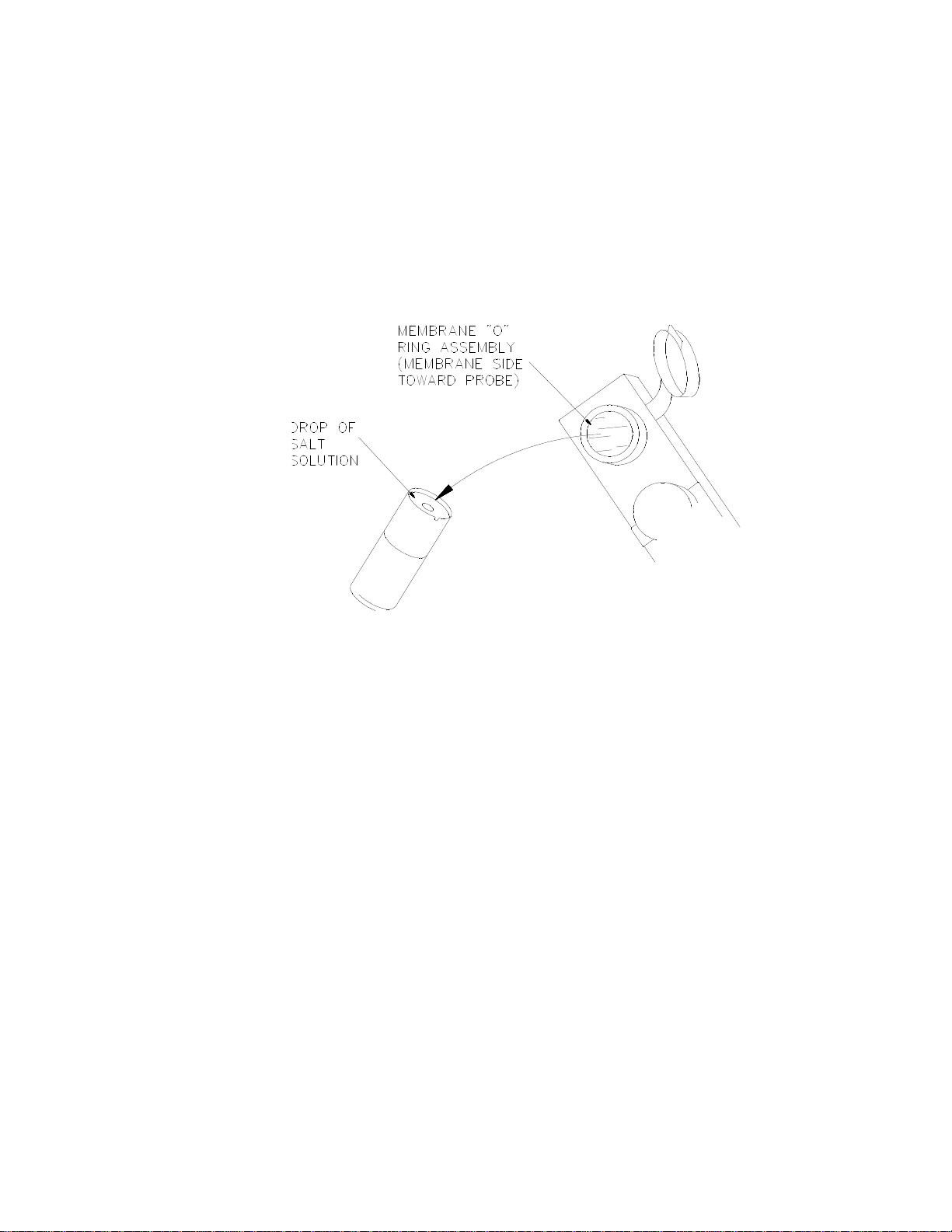
6. Rinse the membrane inside with a few drops of salt solution (YSI 2392).
7. Place one drop of salt solution on the enzyme probe face.
8. Using the plastic membrane holder, press the O-ring membrane assembly gently onto the probe face.
Figure 4.5
9. Wipe excess salt solution from the probe body.
10. Install a stir bar in the module.
11. Then return the enzyme probe to the module.
12. Finger tighten the probe retainer so that the O-ring seals the probe in place. Do not overtighten.
13. Return the membrane holder to the foil pouch and refrigerate it.
14. Note the expiration date on the membrane package
15. Repeat this procedure for the remaining enzyme probes.
You may want to maintain an instrument log book in which dates and lot numbers of reagents are recorded, along with
information from daily operational checks and other relevant information.
4.9.2 Ion Selective Electrodes
The 2900 Series is shipped without the Ion Selective Electrodes installed in module 3. To install an ISE:
1. First remove the packaging material and the cap from the ISE (save the cap for later use).
2. Slide a black probe retainer over each ISE cable (threaded end first).
3. Slide a white probe sleeve (notched end out) over the end of each ISE.
27
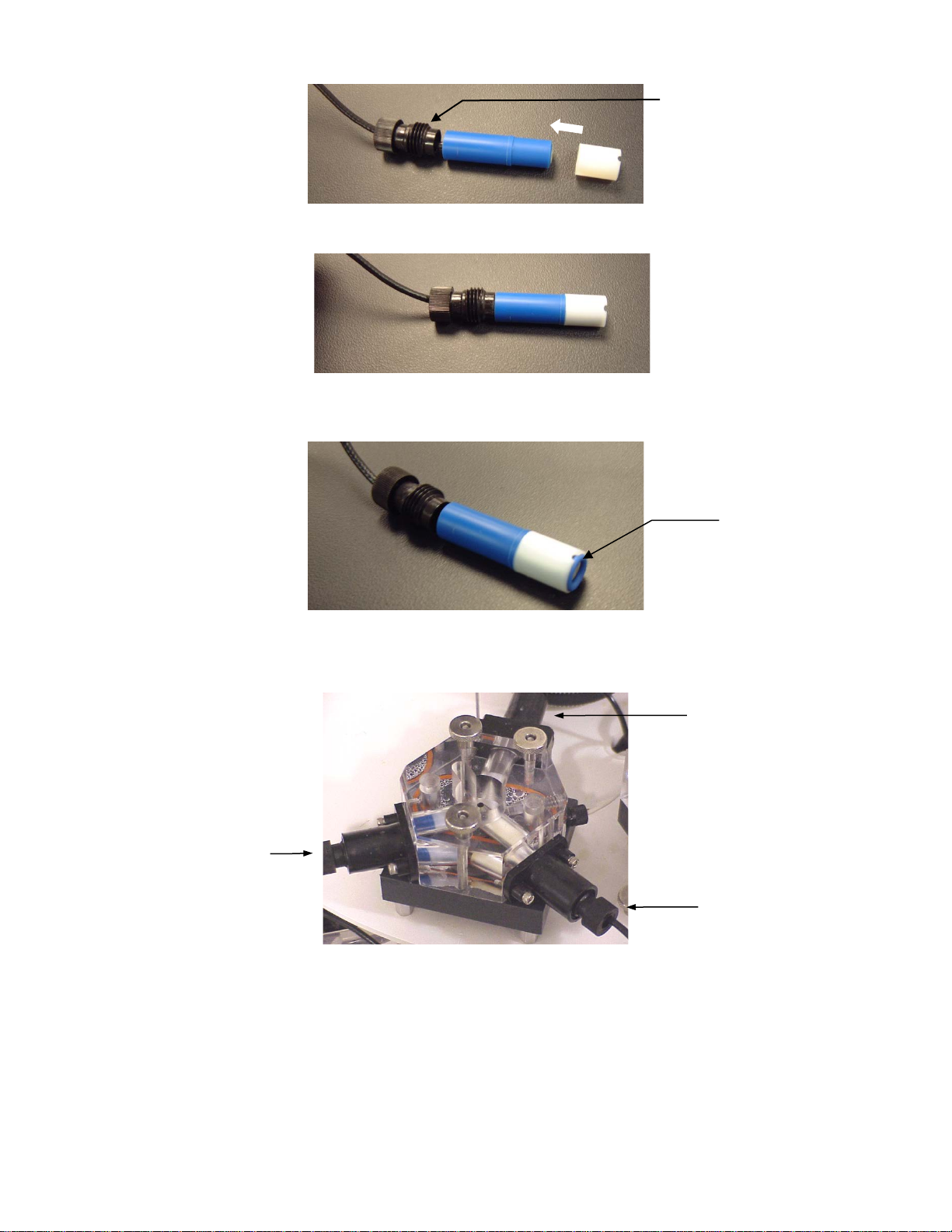
O-ring
Retainer
Potassium ISE
Reference Electrode
Ammonium ISE
Figure 4.6
Figure 4.7
4. Place an O-ring into the end of each sleeve, pushing the O-ring gently so that it is secured by the sleeve.
Figure 4.8
5. Install the reference electrode by screwing the probe retainer into the module (finger tighten only; do not
overtighten).
6. Install a stir bar in the module.
7. Secure the ammonium and potassium ISEs in place by screwing the probe retainers into the module (finger
tighten only; do not overtighten).
8. Connect the ISE cables to the matching connectors located at the rear of the instrument.
Figure 4.9
28
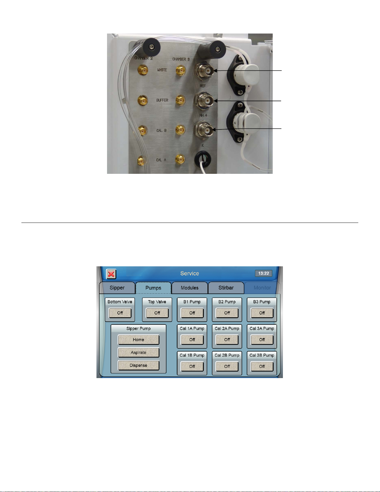
Ammonium—NH4
Potassium—K
Reference—REF
Figure 4.10
9. Install the top covers on the instrument.
Prime the Fluid System 4.10
Please note that it may take from several minutes to more than an hour to initially stabilize the probes when setting up for
the first time.
To prime the fluid system:
1. From the Service screen, touch the [Pumps] tab.
2. Touch the button under B1 Pump to turn it on.
3. The instrument will prime the B1 buffer solution.
4. Once buffer flows from the end of the sipper, touch the button under B1 Pump to stop the pump.
5. Repeat this procedure to prime all other buffer bottles and calibrator bottles you have installed.
Prime all installed calibrator bottles daily to remove air bubbles from the tubing.
29
 Loading...