

YSI 2940, 2980 Operation And Maintenance Manual

YSI Multi-Channel On line
Monitor
Operations and Maintenance Manual

Preface
Information in this guide is subject to change without notice. No part of this guide may be
reproduced or transmitted in any form or by any means, electronic or mechanical, for any purpose,
without the express written permission of YSI Incorporated.
If you have questions or comments regarding the contents of this guide, contact YSI technical support
at 1-800-659-8895 or e-mail at support@ysi.com.
YSI Incorporated made every effort to ensure the information in this guide is correct at the time of
availability. YSI Incorporated reserves the right to make changes without notice as part of ongoing
product development.
Manufacturer and Distributor Address
YSI Incorporated.
Life Sciences
1725 Brannum Lane
Yellow Springs, OH 45387
Toll Free: 1 800-659-8895
Fax: 1 937-767-8058
www.ysilifesciences.com
support@ysi.com
License Statements
Any patents or patent applications are owned by the original equipment manufacturer.
Intended Use
The Multi-Channel Online Monitor is intended for life science applications only and is not intended to be used
for medical or diagnostic procedures.
Use of this Manual
This manual should be read in its entirety before using the Multi-Channel Online Mon itor . This manual is
intended as instructions for its use. It provides information about the system’s installation, operation,
maintenance and troubleshooting.
Symbols Used in this Manual
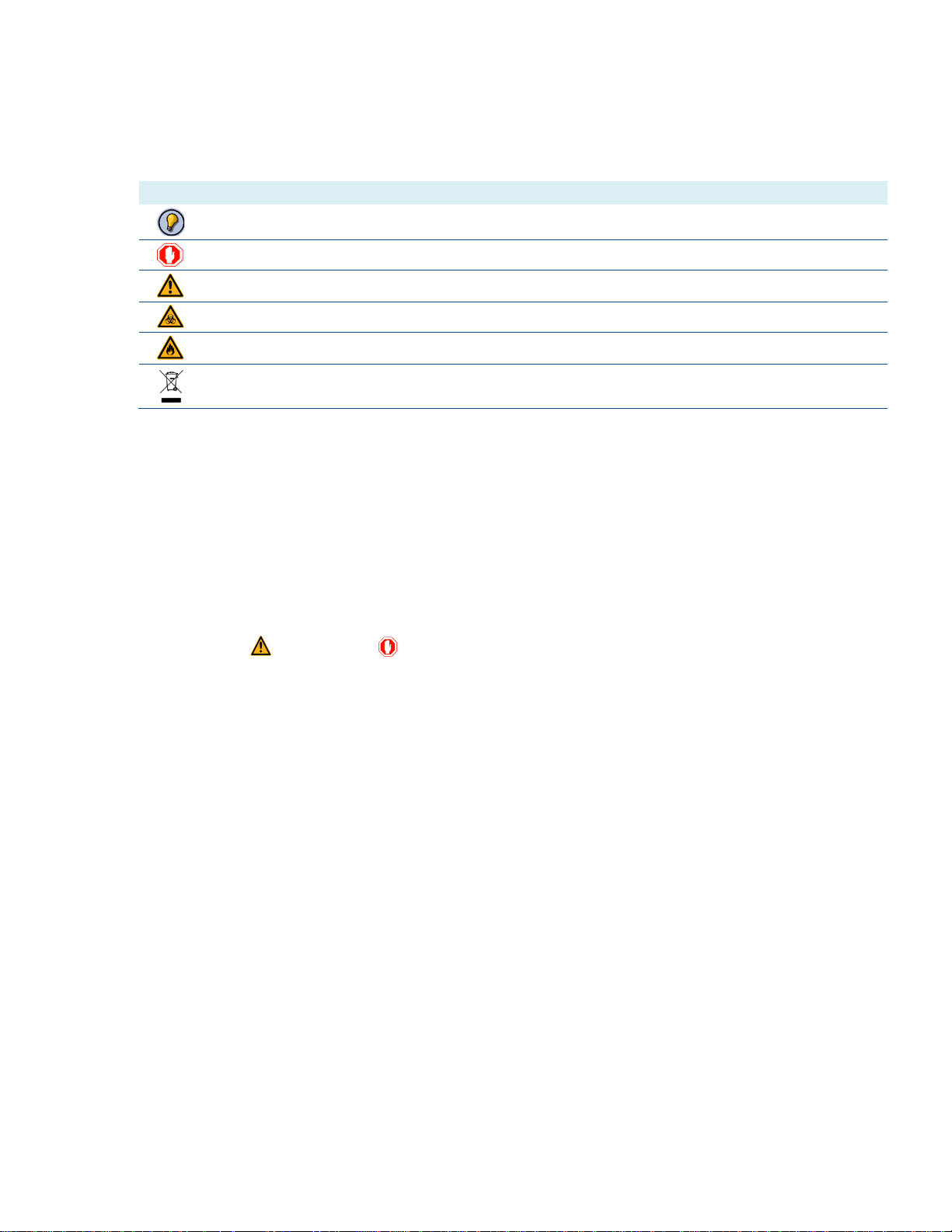
The following symbols may be used in this manual:
Symbol Description
Note. Provides additional details.
Stop. Understand and follow instructions so that system damage or data loss does not occur.
Warning – Risk of Danger. Risk of personal injury to the operator or a safety hazard to the system or surrounding area.
Biohazard. Take the necessary precautions when working with potentially infectious material.
Flammable Materials and Risk of Fire. Observe proper laboratory safety precautions.
Proper disposal of waste electrical and elect roni c equipm ent (WEEE ).
Observe all national, regional, and local regulations for waste disposal and management.
Warnings and Precautions
Handling Requirements
Only trained, skilled personnel should use the Multi-Channel Online Monitor. It is essential that all users
carefully read and observe the following safety information. Always follow basic safety precautions during use
to reduce the risk of injury or electrical shock.
• Read, understand, and follow all information in this manual. Failure to do so could result in damage to the
Multi-Channel Online Monitor, injury to operating personnel, or poor system performance.
• Observe all (Warning) and (Stop) statements in this manual.
• Observe proper laboratory safety precautions, such as wearing personnel protective equipment and using
approved laboratory safety procedures.
Ensure that this safety information is accessible for every person using the Multi-Channel Online Monitor. It is
assumed that trained users are familiar with the necessary safety precautions for handling chemicals and
biohazardous materials. Observe the following laws and guidelines:
• National industrial protection law
• Accident prevention regulations
• Material Safety data sheets (MSDS) of the reagent manufacturers
ii

Table of Contents
Preface .......................................................................................................................... i
Manufacturer and Distribut or Addres s ................................................................... i
License Statements ............................................................................................... i
Intended Use ......................................................................................................... i
Use of this Manual ................................................................................................. i
Symbols Used in this Manual ............................................................................... ii
Warnings and Precautions ................................................................................... ii
1 Introduction ............................................................................................................ 1
1.1 System Overview ............................................................................................. 1
1.2 Analyzer Integration ......................................................................................... 2
1.3 Capabilities ...................................................................................................... 2
1.4 User Features .................................................................................................. 2
1.5 System Configuration ...................................................................................... 3
1.5.1 Multi-Channel Online Monitor/YSI 2900 Series System ........................... 3
1.5.2 2940 - Four Vessels .................................................................................. 3
1.5.3 2980 - Eight Vessels ................................................................................. 3
1.6 Major Components .......................................................................................... 4
1.6.1 Multi-Channel Online Monitor – Front Panel ............................................. 4
1.6.2 Multi-Channel Online Monitor – Rear Panel ............................................. 5
1.6.3 Multi-Channel Online Monitor – Top Panel ............................................... 6
1.6.4 Flownamics In situ Sampling Probe (FISP®)............................................. 6
2 Installation .............................................................................................................. 9
2.1 Unpacking the Multi-Channel Online Monitor .................................................. 9
2.2 Installing the Multi-Channel Online Monitor Components ............................... 9
2.2.1 Electrical Connections ............................................................................ 10
2.2.2 Tubing Installation ................................................................................... 12
2.2.3 Reagent and Waste Bottle Installation .................................................... 13
2.2.4 Installing the Monitor Sample Cup and Sample Tubing.......................... 15
2.3 Configuring the Analyzer ............................................................................... 18
2.3.1 Programming the RS-232 communication settings ................................ 18
2.3.2 Bottle Fluid Detection .............................................................................. 18
2.3.3 21 CFR Part 11 ....................................................................................... 19
2.3.4 Sipper Alignment ..................................................................................... 19
2.3.5 Sipper Depth ........................................................................................... 21
2.4 Connecting Vessels to the Multi-Channel Online Monitor ............................. 22
2.4.1 Sample Probe Installation ....................................................................... 22
2.4.2 Connecting the Sample Line ................................................................... 25
2.5 Fluid Path Sterility Considerations ................................................................ 25
2.5.1 Autoclaved Vessels ................................................................................. 25
2.5.2 SIP Vessels ............................................................................................. 25
3 Administrative Functions.................................................................................... 27
3.1 Logging into Administration ........................................................................... 27
3.2 Adding and Managing User Accounts and Permissions ............................... 28
3.2.1 Adding or Deleting a User Account ......................................................... 28
3.2.2 Editing User Acc ounts ............................................................................. 29
3.2.3 Setting and Changing User Permissions ................................................ 30
3.3 Changing the Date and Time Settings .......................................................... 31
3.4 Setting up the Network IP Address ............................................................... 32
3.4.1 Resetting the Network Card .................................................................... 32
3.5 Changing the Administrative Password ......................................................... 33
3.6 OPC Connectivity Settings ............................................................................ 33
3.7 Configuring the Audit Trail ............................................................................. 35
3.8 Touchscreen Calibration ................................................................................ 36
iii

Operation .............................................................................................................. 37
4
4.1 Turning on the Multi-Channel Online Monitor ................................................ 37
4.2 Software Overview ........................................................................................ 38
4.3 Status Lights .................................................................................................. 38
4.4 Logging into the System ................................................................................ 38
4.5 Configuring the System Settings ................................................................... 40
4.5.1 Pump Settings ......................................................................................... 40
4.5.2 Rinse and Antiseptic Settings ................................................................. 41
4.5.3 Bottle Check ............................................................................................ 42
4.5.4 Chemistry Configuration ......................................................................... 42
4.5.5 Analog Output Configuration ................................................................... 43
4.6 Vessel Sampling ............................................................................................ 44
4.6.1 Setting up Individual Vessels: Standard Sampling ................................. 44
4.6.2 Priming a Vessel Line ............................................................................. 46
4.6.3 Prepare the 2900 Series Analyzer for Monitoring ................................... 46
4.6.4 Starting the Monitor System .................................................................... 48
4.6.5 Stopping the Monitor System .................................................................. 49
4.6.6 Starting a Priority Sample ....................................................................... 49
4.6.7 Scheduler Sampling ................................................................................ 49
4.7 Data Acquisition and Exporting ..................................................................... 54
4.7.1 Tabulating the Data ................................................................................. 54
4.7.2 Data Filter ................................................................................................ 55
4.7.3 Graphing the Data ................................................................................... 56
4.7.4 Exporting the Data .................................................................................. 59
4.8 System Monitoring ......................................................................................... 60
4.8.1 Status Monitoring .................................................................................... 60
4.9 Changing the User’s Password ..................................................................... 61
4.10 Installing Software Updates ........................................................................... 61
4.11 Creating, Restoring and Removing Backup Files.......................................... 62
4.11.1 Creating a Backup File ............................................................................ 62
4.11.2 Restoring a Backup File .......................................................................... 63
4.11.3 Removing a Backup File ......................................................................... 64
4.12 Shutting Down, Logging Out or Restarting .................................................... 64
4.13 Remotely Accessing ...................................................................................... 65
4.14 Support .......................................................................................................... 65
4.14.1 Support Icon ............................................................................................ 65
4.14.2 Audit Trail ................................................................................................ 66
4.14.3 Alerts Display .......................................................................................... 68
5 Maintenance ......................................................................................................... 70
5.1 Routine Maintenance ..................................................................................... 70
5.1.1 Daily Maintenance................................................................................... 70
5.1.2 Preventive Maintenance ......................................................................... 71
5.2 Component Replacement .............................................................................. 71
5.2.1 Pump Tubing ........................................................................................... 71
5.2.2 Waste and Reagent Bottle Lines ............................................................ 72
5.2.3 Monitor Cup Sample and Waste Lines ................................................... 73
5.2.4 FISP Membrane Replacement ................................................................ 73
5.3 Cleaning ......................................................................................................... 73
5.3.1 General Cleaning Procedures ................................................................. 73
5.3.2 Component Cleaning .............................................................................. 73
5.3.3 FISP Probe and Membrane .................................................................... 74
5.3.4 Touchscreen Monitor .............................................................................. 74
5.4 System Shutdown .......................................................................................... 75
6 Troubleshooting .................................................................................................. 76
6.1 Troubleshooting Basics ................................................................................. 76
6.2 Online Monitor Troubleshooting Guide .......................................................... 76
iv

Appendices .......................................................................................................... 81
7
7.1 Appendix A Specifications ............................................................................. 81
7.2 Appendix B Replacement Parts and Consumables ...................................... 82
7.3 Appendix C Decontamination and Disposal .................................................. 83
7.3.1 General Decontamination Considerations .............................................. 83
7.3.2 Decontamination of the Multi-Channel Online Monitor ........................... 83
7.3.3 Disposal of the Multi-Channel Online Monitor ........................................ 83
7.4 Appendix D Warranty and Repair .................................................................. 85
7.4.1 Limitation of Warranty ............................................................................. 85
7.4.2 Cleaning Instructions for Instrument Return ........................................... 85
7.4.3 Shipping Instructions ............................................................................... 86
7.4.4 YSI Factory Authorized Service C ent ers ................................................ 87
7.5 Appendix E CE Compliance .......................................................................... 88
7.6 Appendix G FCC Required Notice................................................................. 89
7.7 Appendix H Authorized Reagent Use ............................................................ 90
7.8 Declaration of Conformity–USA and Canada ................................................ 91
v
1 Introduction
1.1 System Overview
The YSI Multi-Channel Online Monitor is a fluid and data management device that is designed to withdraw samples from
up to eight bioreactors, fermentation vessels, fluid reservoirs, or liquid streams and deliver them to the YSI 2900 Series
Biochemistry Analyzer for on-line, real-time analysis and process monitoring. The Multi-Channel Online Monitor allows a
range of sample volumes to be obtained and rapidly delivered to distances up to 10 feet (3 meters) away. Other process
control and monitoring options can be realized using the Multi-Channel Online Monitor’s analog output and OPC
connectivity functions.
The Multi-Channel Online Monitor software is we b -based software that is preloaded onto the system’s internal
processor. Because of this web-based design, the Multi-Channel Online Monitor can be remotely controlled,
configured, and monitored from any computer using a web browser and assigned IP network address. Additionally,
the software is 21 CFR, part 11 compliant and can be integrated to communicate seamlessly with other software
systems.
1

1.2 Analyzer Integration
The Multi-Channel Online Monitor interfaces with YSI 2900 Series Biochemist r y Analyzers, whic h permits on-line, real-time
nutrient and metabolite analysis for various bioprocessing applications for the pharmaceutical, food and beverage and
biofuel industries.
1.3 Capabilities
• Automated sampling of up to 8 vessels (2980)
• Cell-free and/or cell-containing sampling
• Rapid delivery to the YSI 2900 Series Analyzer
• Analog output of up to two (2) chemistries per vessel
• Multiple bioreactor integration options
• Serial communication interface
• Provides near real-time analysis of nutrients and metabolites
• Integrated data management for YSI 2900 Series Analyzer
• Data transfer to any SCADA system or historian via TCP/IP or OPC connectivity
• Remote monitor and control of sampling and data
1.4 User Features
• Disposable fluid path to reactor and 2900 Series Analyzer
• Pre-sterilized tubing assemblies
• Automated sampling
• Automated system cleaning
• Touch Screen HMI
• Internal web server control
• 21 CFR, Part 11 compliant software
• OPC server option available
• Compact design
2
1.5 System Configuration
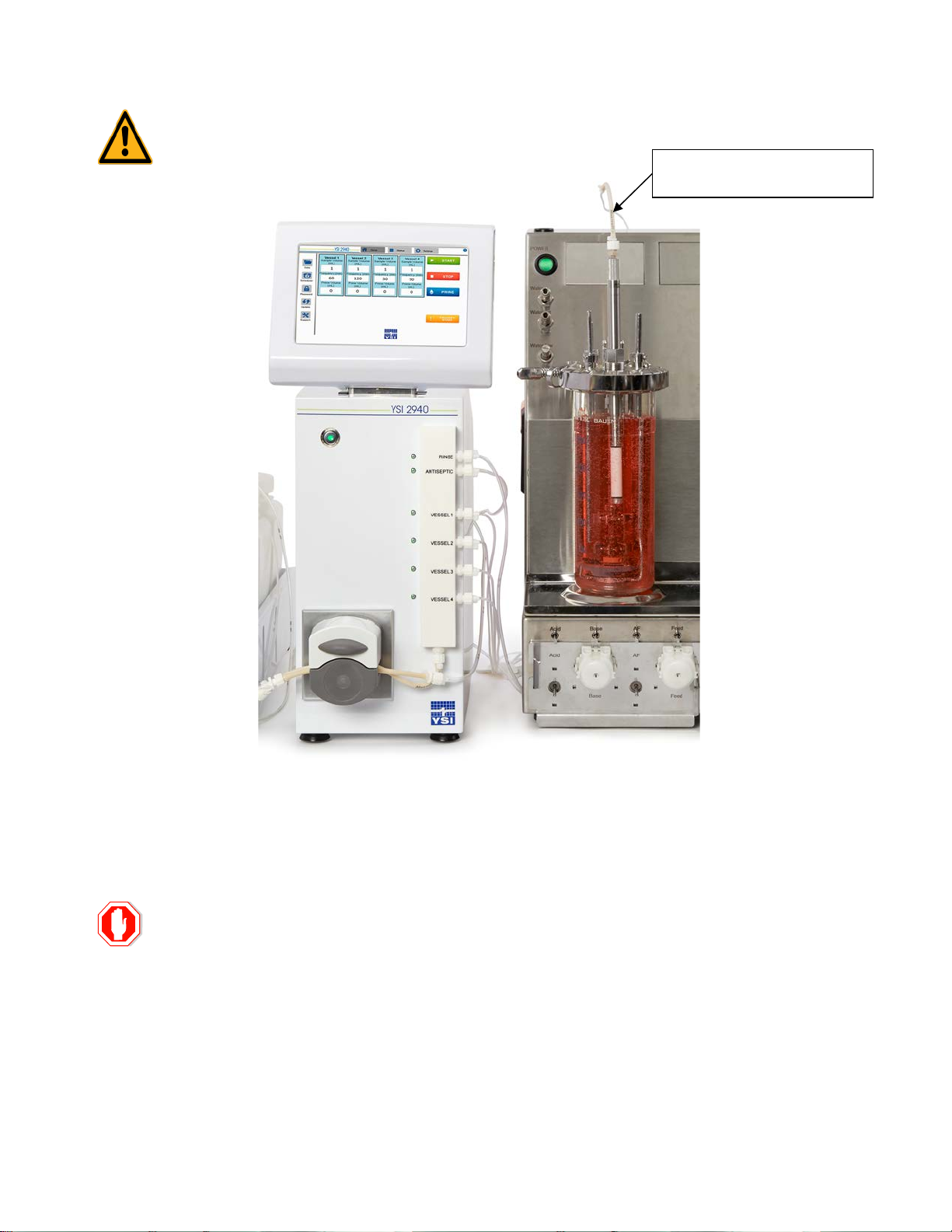
The YSI 2900 Series Analyzer is typically placed within close proximity of the Multi-Channel Online Monitor. Shorter fluid
paths are recommended for sample precision and accuracy. Typical configurations are shown in the figures below.
These system configurations are shown for illustration purposes. Different laboratory/production facility designs, vessel
locations and benchtop/shelving spacing may dictate different locations for the Multi-Channel Online Monitor a nd/or YSI
2900 Series Analyzer with regards to in the proximity of the vessel to be analyzed.
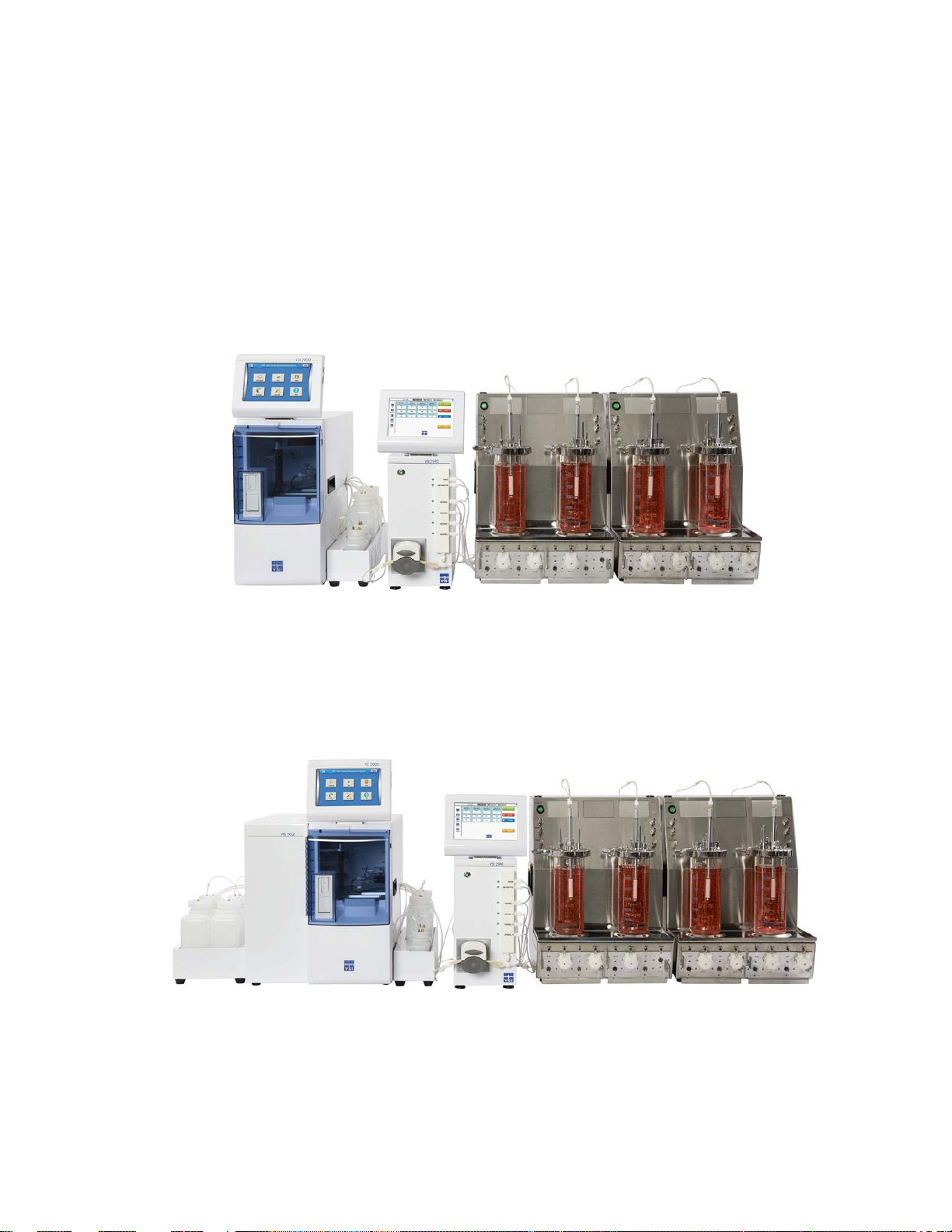
1.5.1 Multi-Channel Online Monitor/YSI 2900 Series System
Figure 1-1
1.5.2 2940 - Four Vessels
The 2940 4-Channel Online Monitor System allows automated sampling from up to four vessels and sample delivery to the
YSI 2900 Series Analyzer.
Figure 1-2
1.5.3 2980 - Eight Vessels
The 2980 8-Channel Online Monitor allows automated sampling from up to eight vessels and sample delivery to the YSI
2900 Series Analyzer.
3
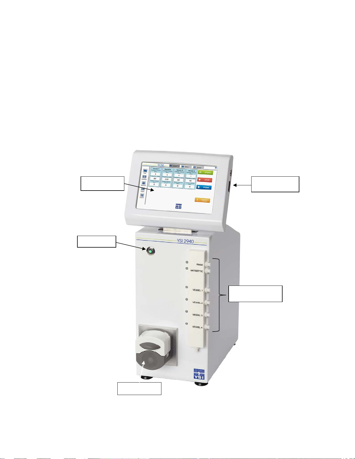
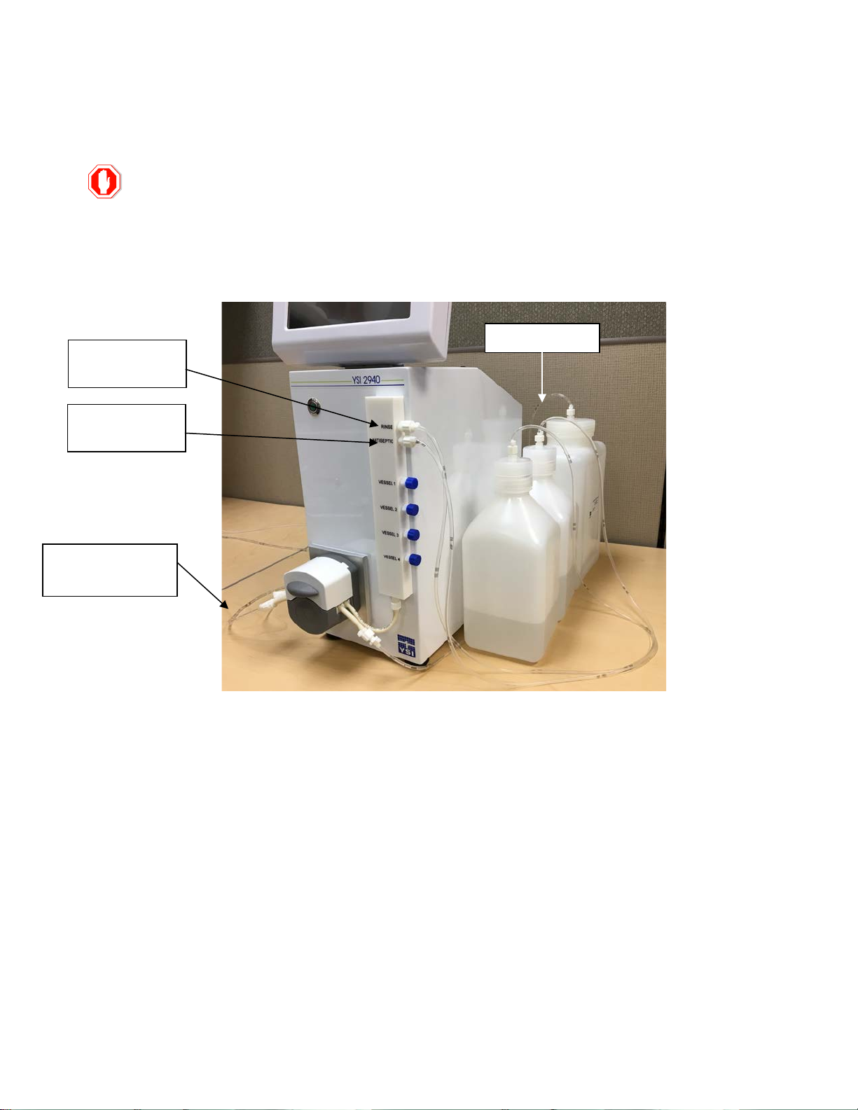
Power button
Peristaltic Pump
Display Panel/
Vessel & Reagent
USB Connection
1.6 Major Components
The major components of the Multi-Channel Online Monitor System are shown in the following figures and briefly described
below.
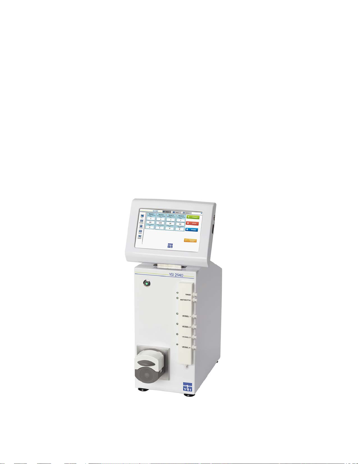
1.6.1 Multi-Channel Online Monitor – Front Panel
The front panel contains the power button, display panel/touchscreen interface, peristaltic pump, and the fluid stream
management devices for sample, waste and reagent stream management. The following figure shows the front panel for
the basic setup.
Line Connections
Figure 1-3
4
The Multi-Channel Online Monitor must be powered off prior to connecting or disconnecting any cables
Analyzer.
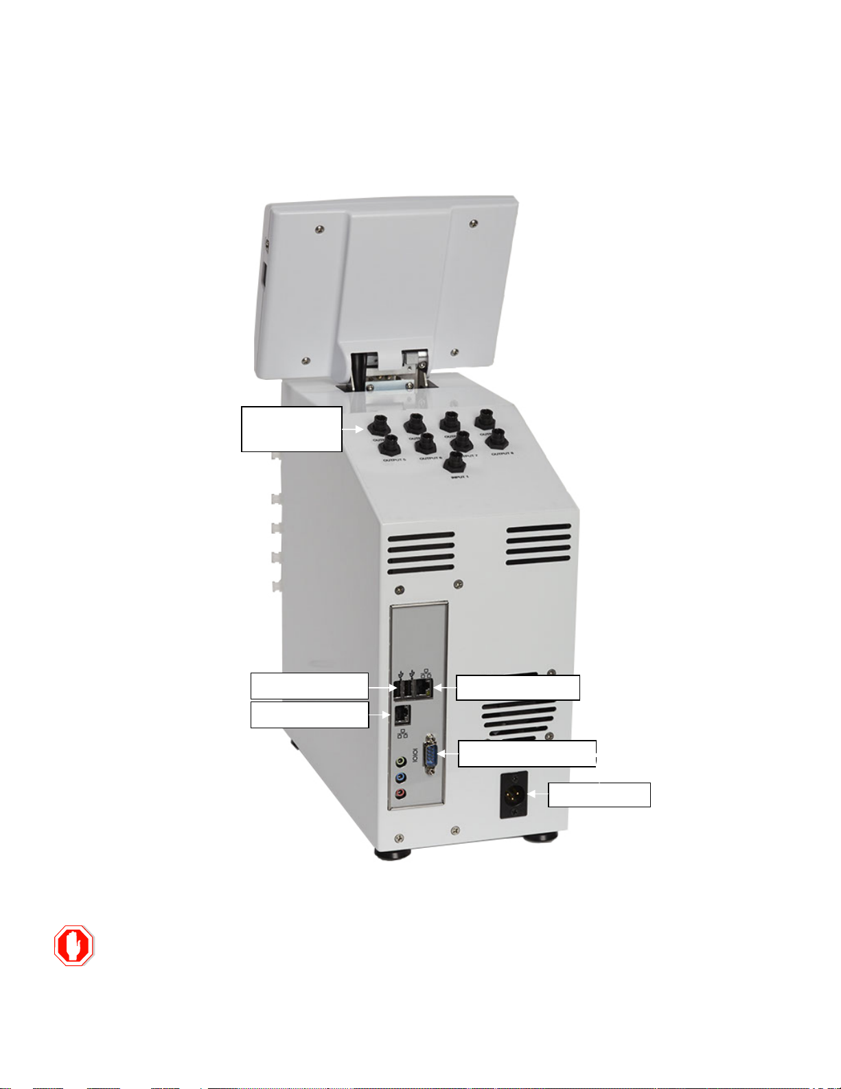
Analog
Serial Com Port
Network Port
Network Port
DC Power
USB Ports
1.6.2 Multi-Channel Online Monitor – Rear Panel
The rear panel houses the connections for the power cord, the serial port and TCP/IP connectivity.
Outputs
Figure 1-4
from the top or rear communication panels. Connecting or disconnecting cables with the power on may
cause software and/or communication errors with the Multi-Channel Online Monitor and YSI 2900 Series
5
The Multi-Channel Online Monitor must be powered off prior to connecting or disconnecting any cables
Analyzer.
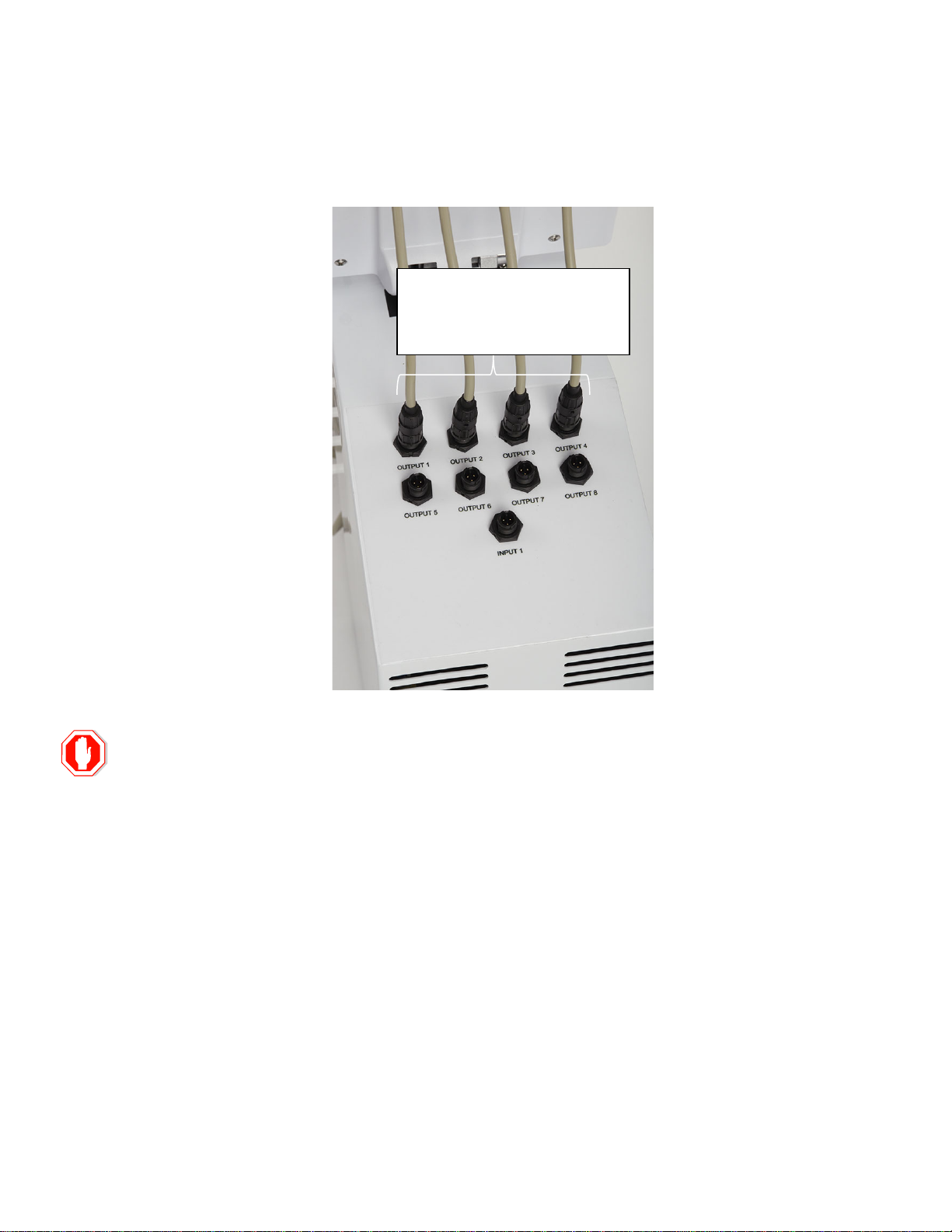
2940: Eight 0-5 V Analog Outputs
1.6.3 Multi-Channel Online Monitor – Top Panel
The top panel serves as the communication interface for the Analog Output (DAC) connections.
(2 outputs/connection)
2980: Sixteen 0-5 V Analog Outputs
(2 outputs/connection)
Figure 1-5
from the top or rear communication panels. Connecting or disconnecting cables with the power on may
cause software and/or communication errors with the Multi-Channel Online Monitor and YSI 2900 Series
1.6.4 Flownamics In situ Sampling Probe (FISP
FISP sampling probes are used to obtain cell-free samples as well as provide a vessel sampling interface for the MultiChannel Online Monitor. These probes are sold separately. The FISP probes provide direct transfer of the vessel contents
as well provide a sterile barrier for the vessel. The sterile barrier is obtained through the use of a sterilized 0.2 um ceramic
membrane mounted onto the FISP housing (Figure 1-6 & Figure 1-7). Refer to the FISP Sampling Probe User’s Guide for
additional details.
There are two basic types of FISP sampling probes, which are the D-Series and the F-Series sampling probes.
®
)
6
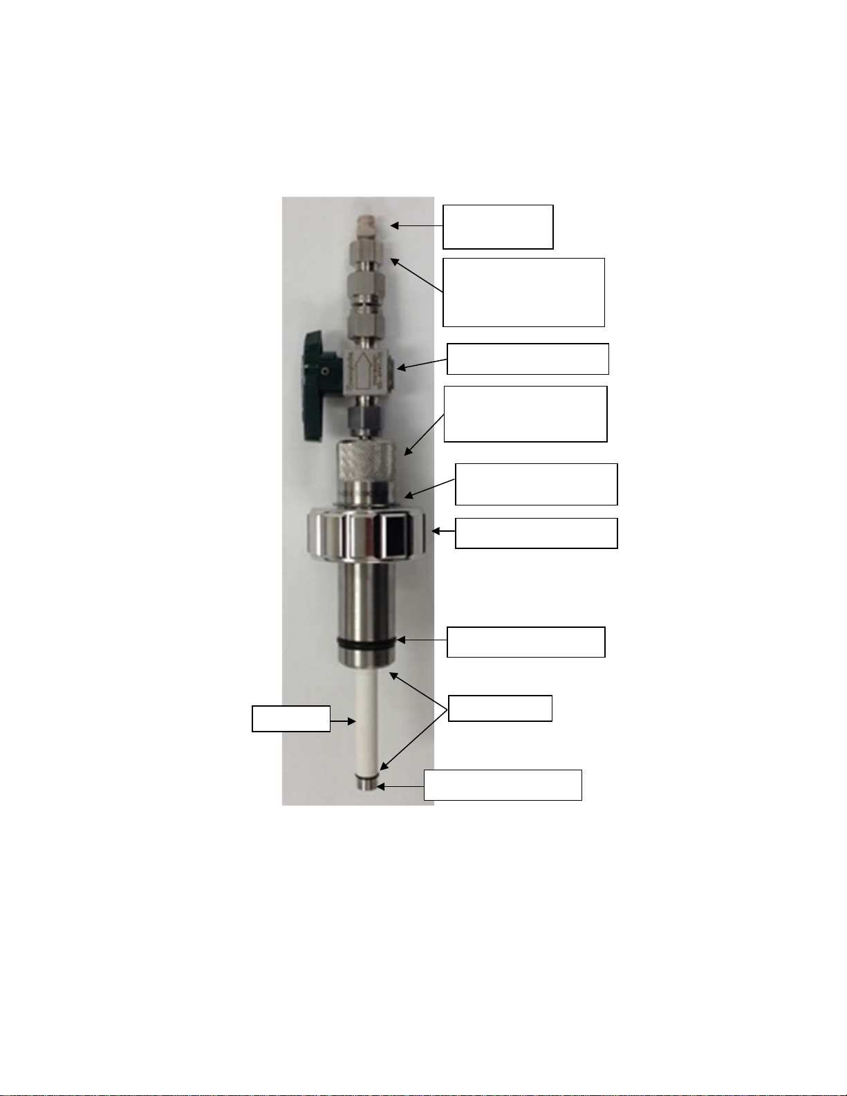
O-Ring, EPDM
Membrane
O-Rings, EPDM
End Cap Screw, 316-SS
2 Way Plug Valve, 316-SS
Probe Body
25 mm Retaining Nut
1” External Retaining Ring,
PEEK female luer
SS ¼” Tubing Adapter and
1.6.4.1 D-Series – FISP Cell-Free Sampling Probe
The D-Series probes are used for Steam-in-Place (SIP) or autoclaveable stainless steel vessels which have a 25 mm
Ingold port in the vessel wall. Additionally, the D-series probes can be fitted for both standard (40 mm) and safety port (52
mm) depths. The Luer configuration is designed for use with the Multi-Channel Online Monitor system (Figure 1-6).
connector
PEEK Female Luer to 10-32
Male Fitting
25 mm D-Series Safety
Sampling Probe
Figure 1-6
316-SS (Not shown)
7
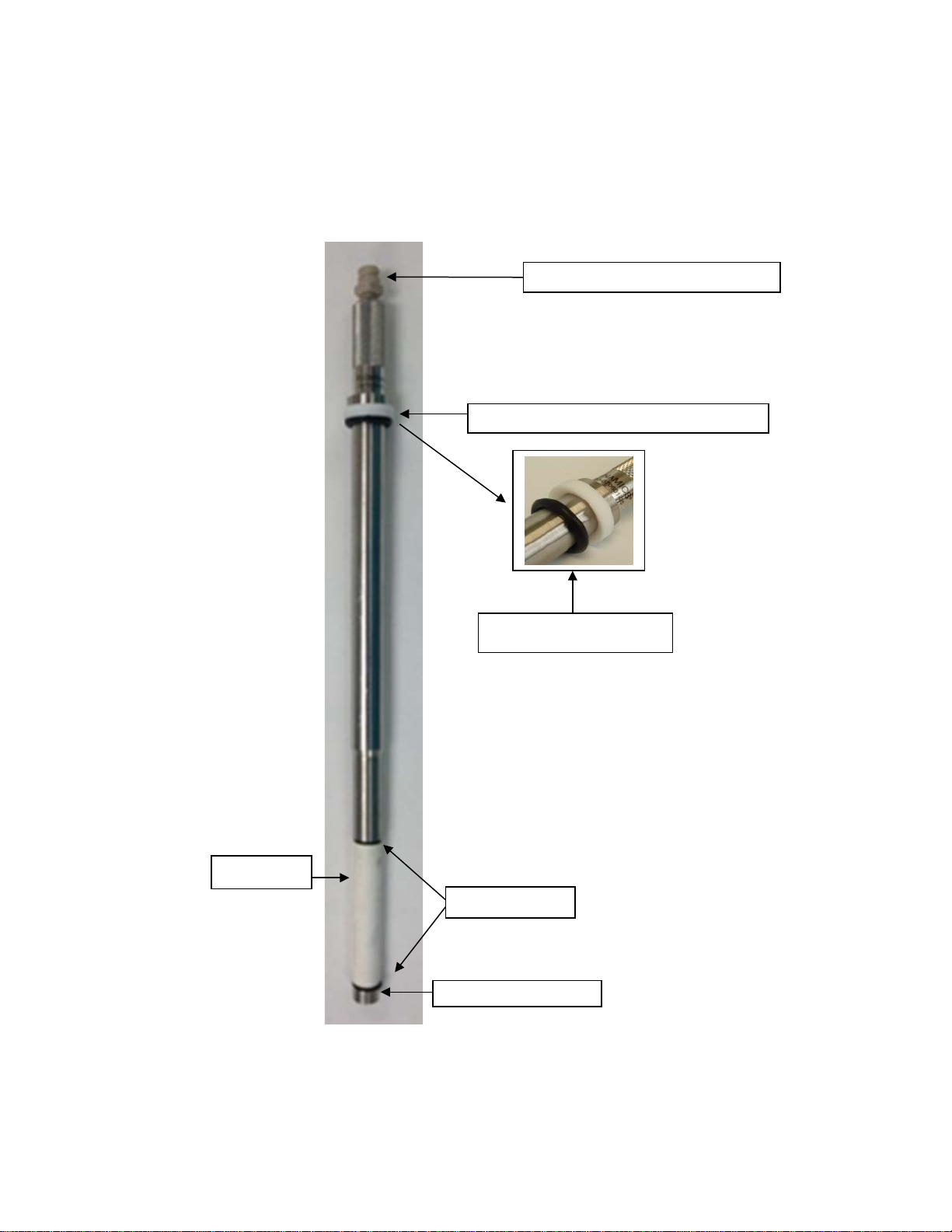
Membrane
O-Rings, EPDM
End Cap Screw, 316-SS
Beveled Washer/O-Ring Kit for F-Series Probe
Beveled Washer facing O-Ring
Female Luer Adapter to 10-32, PEEK, tan
1.6.4.2 F-Series – FISP Cell-Free Sampling Probe
The F-Series probes are used for autoclaveable glass vessels which have a 12 mm or 19 mm headplate port. Additionally,
the F-series probes come in a variety of lengths to fit various vessel sizes and depths. Figure 1-13 details the F-Series
sampling probe. The standard configuration is provided with a PEEK female Luer connector, which is designed for use with
the Multi-Channel Online Monitor (Figure 1-7).
Figure 1-7
8

The Multi-Channel Online Monitor must be powered off prior to connecting or disconnecting any cables
Analyzer.
2 Installation
2.1 Unpacking the Multi-Channel Online Monitor
1. Inspect the shipping container(s) for damage due to shipping.
2. If the shipping box appears damaged in any way, immediately contact YSI Technical Support.
3. Remove the Multi-Channel Online Monitor components from the shipping box.
4. Verify the shipment contents using the enclosed packing list and packing check list to ensure the following items
are present:
• 2940 or 2980 Multi-Channel Online Monitor
• Power cord
• Power supply
• Reagent bottles with cap/tubing assemblies (2)
• Waste bottle with cap/tubing assembly
• Monitor Sample Cup
• 2877 Peristaltic pump tubing set
• 2876 Monitor Sample Cup tubing set
• Serial (null modem) communication cable (DB9 to DB9 connectors)
• Analog output cables (4 or 8, depending on which system was ordered)
2.2 Installing the Multi-Channel Online M onitor Components
Place the components of the Multi-Channel Online Monitor on a counter or cart where it will be stationed. YSI recommends
that the Multi-Channel Online Monitor power supply be used with a surge protector.
from the top or rear communication panels. Connecting or disconnecting cables with the power on may
cause software and/or communication errors with the Multi-Channel Online Monitor and 2900 Series
9
The Multi-Channel Online Monitor must be powered off prior to connecting or disconnecting any cables
Analyzer.
2.2.1 Electrical Connections
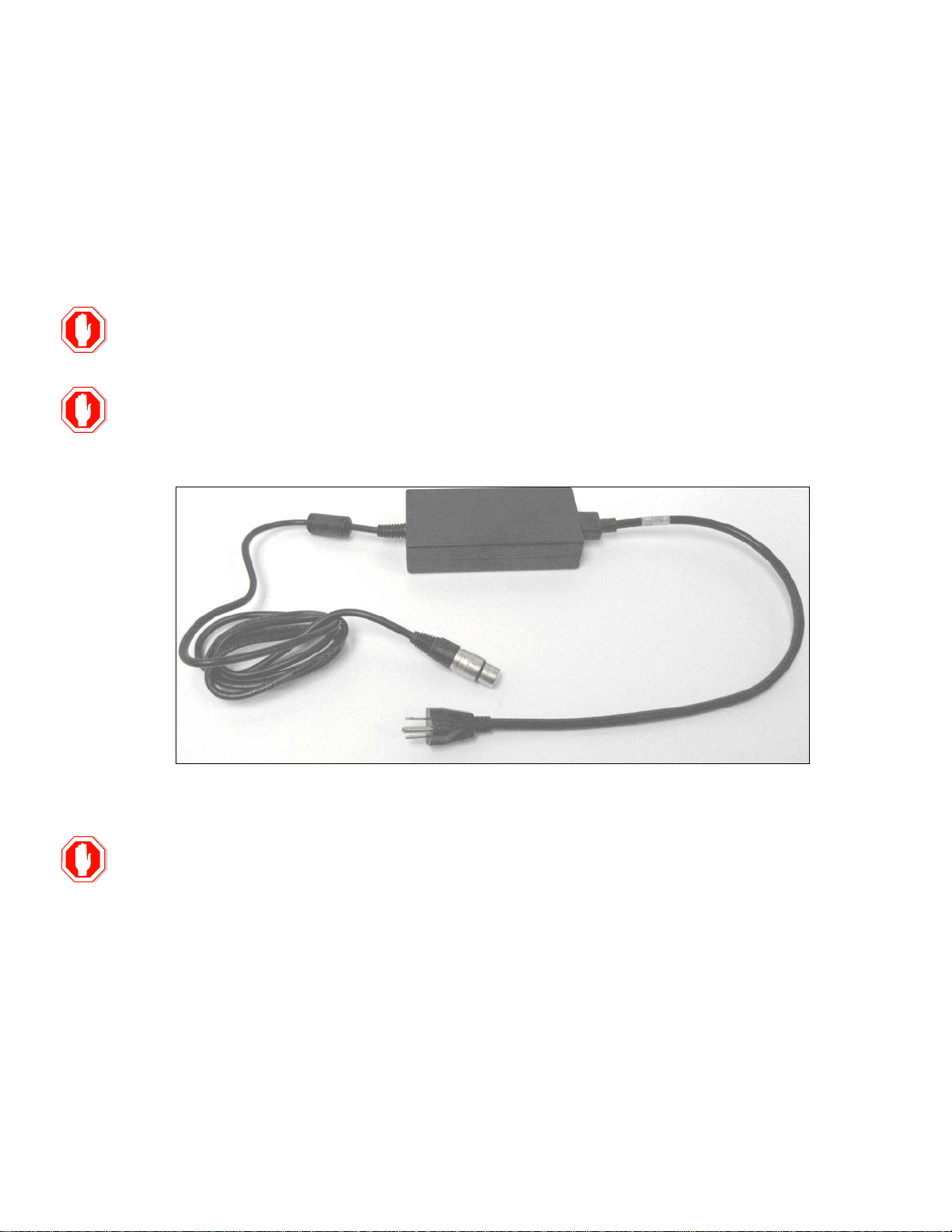
2.2.1.1 Power Supply
1. Connect the Multi-Channel Online Monitor DC power connector (Figure 2-1) to the rear panel DC
power port (Figure 1-4).
2. Connect the Multi-Channel Online Monitor power cord to a surge-protected power strip.
Use the power supply that is shipped with the system. Failure to do so will void the manufacturer’s
warranty.
Do not power on the Multi-Channel Online Monitor until after the communication and tubing connections
have been made.
Figure 2-1
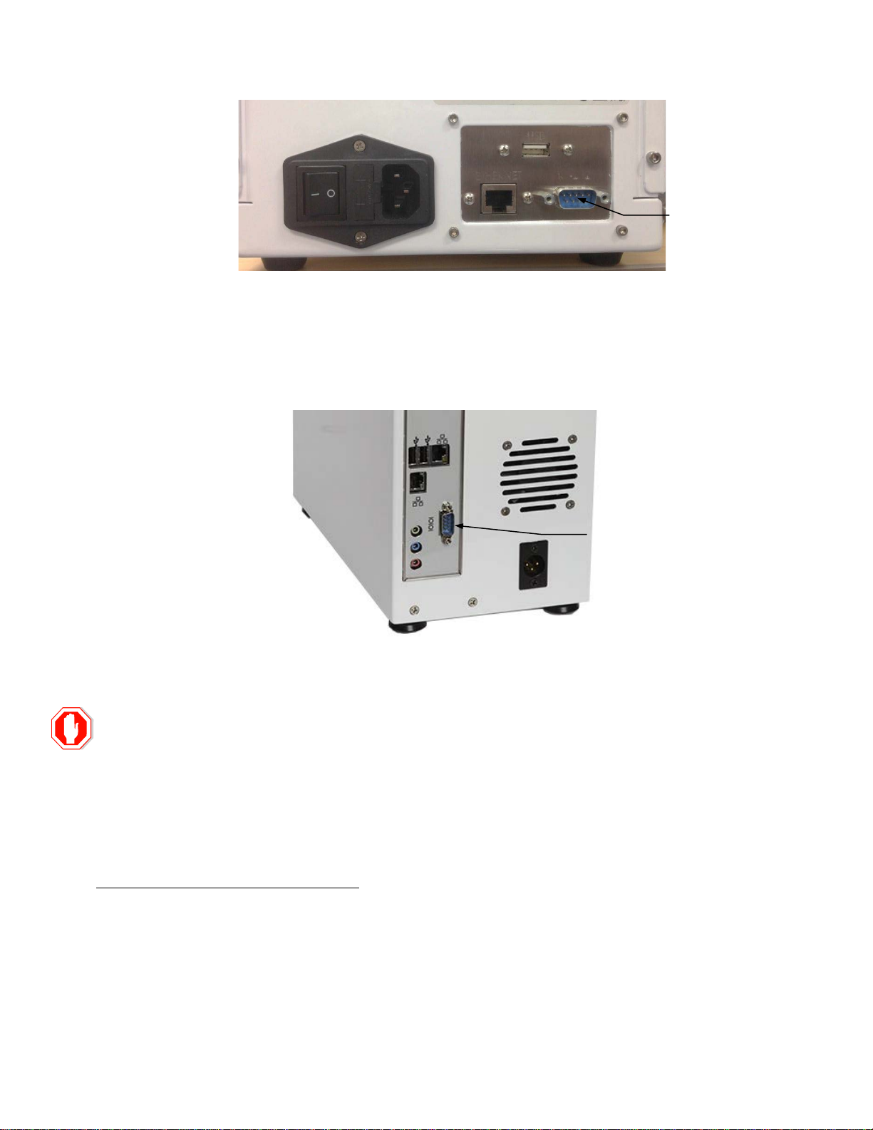
2.2.1.2 Connecting the Serial Communication Cable
from the top or rear communication panels. Connecting or disconnecting cables with the power on may
cause software and/or communication errors with the Multi-Channel Online Monitor and 2900 Series
1. Connect one end of the serial cable (9-pin connector) to the YSI 2900 Series 9-pin RS-232 serial
communication port
two connector thumbscrews.
located on the rear panel of the analyzer (Figure 2-2). Fasten the connector securely with the
10
The Multi-Channel Online Monitor must be powered off prior to connecting or disconnecting any cables
Analyzer.
Signal
Wire Color
Vessel X Output A
Red
Vessel X Output B
Gray
Ground
Black
RS232 Port
RS232 Port
Figure 2-2
2. Connect the other end of the serial cable (9-pin connector) to the RS-232 serial communication port located
on the rear panel of the Multi-Channel Online Monitor (Figure 2-3).
connector thumbscrews.
Fasten the connector securely with the two
Figure 2-3
2.2.1.3 Analog Outputs
from the top or rear communication panels. Connecting or disconnecting cables with the power on may
cause software and/or communication errors with the Multi-Channel Online Monitor and 2900 Series
The 2940 provides up to 8 analog outputs, 2 per vessel, from Output connectors 1–4. The 2980 provides up to 16 analog
outputs, 2 per vessel, from Output connectors 1–8. See Figure 1-5 for location of the Output connectors.
Each output connector provides two 0–5VDC analog signals as shown in the following table.
Refer to Section 4.5.5 Analog Output Configuration to select the chemistry associated with each output.
11
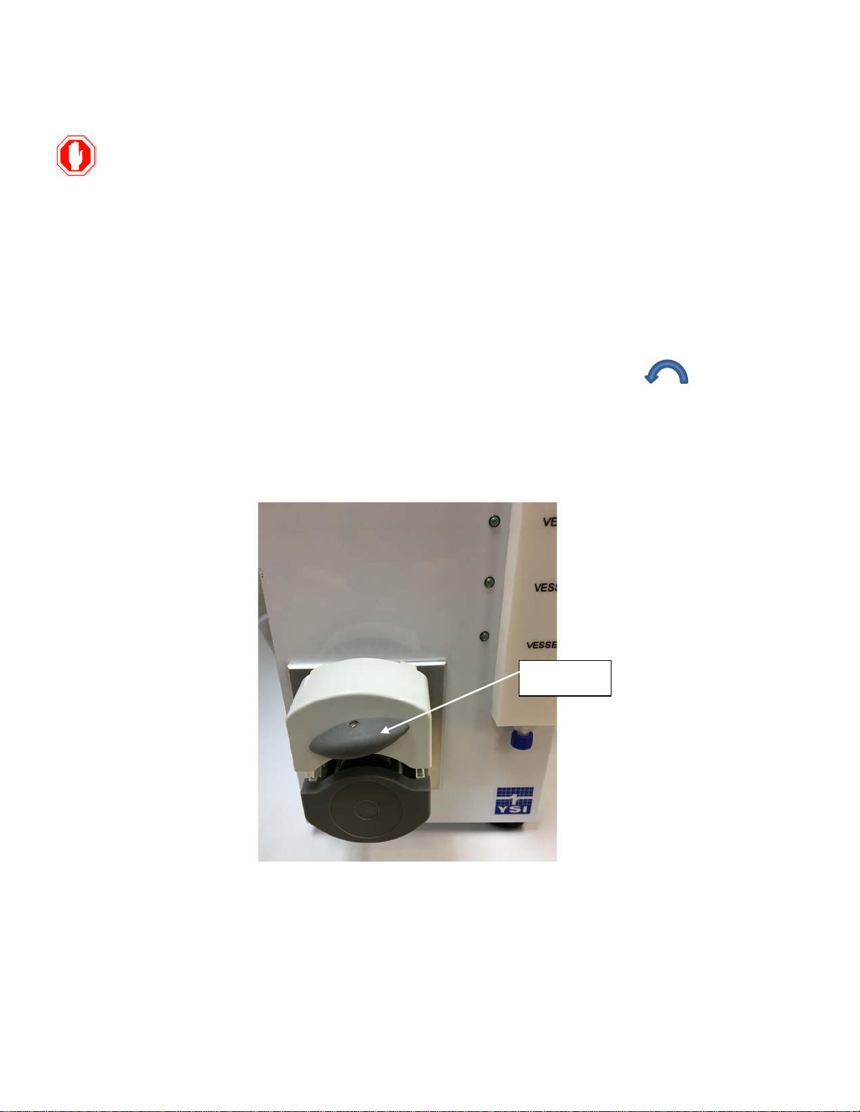
Release Knob
2.2.2 Tubing Installation
All tubing assemblies used with the Multi-Channel Online Monitor are not compatible for vacuum
autoclave cycles. Do NOT use any vacuum autoclave cycles when autoclaving these items,
Vacuum cycles include pre-vacuum and post-autoclave vacuum drying cycles.
The Tubing Manifold cannot be autoclaved.
2.2.2.1 Peristaltic Pump Tubing
2.2.2.1.1 Pump Sample Tubing
1. Carefully remove the new peristaltic pump sample tubing (smaller diameter tubing) from its package.
2. Open the peristaltic pump by turning the release knob counterclockwise (Figure 2-4).
3. Connect the male Luer end of the pump sample tubing to the bottom fitting of the manifold (Figure 2-5).
Figure 2-4
4. Insert the pump sample tubing into the rear slot of the peristaltic pump.
5. Connect the female Luer end of the pump sample tubing to the 2900 Series Analyzer’ s sample line connector.
See Section 2.2.4.3 Sample and Waste Line Installation, for sample line connections.
12
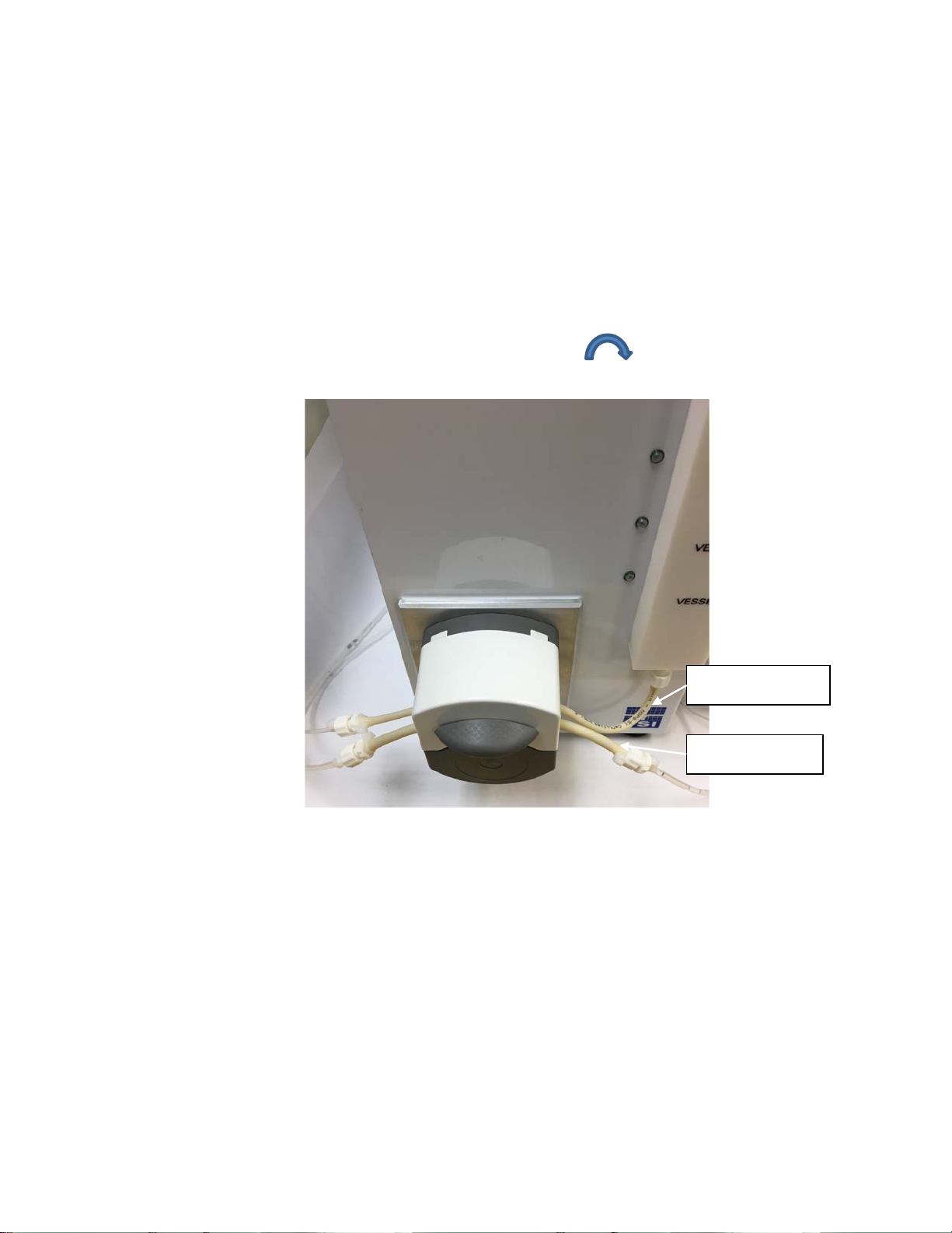
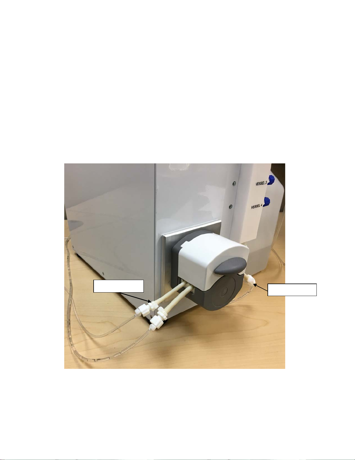
Pump Sampl e Tubing
Pump Wast e Tubing
2.2.2.1.2 Pump Waste Tubing
1. Carefully remove the new peristaltic pump waste tubing (larger diameter tubing) from its package.
2. Insert the pump waste tubing into the front slot of the peristaltic pum p (Figure 2-5). NOTE: Male Luer end on right
side of pump.
3. Verify the tubing is aligned with the V notches in the pump.
4. Close the peristaltic pump by turning the release knob clockwise firmly until it snaps closed. NOTE:
Ensure that the pump tubing stays in place as the pump is closed.
5. Connect the 2900 Series Ana l yzer ’s waste line from the sample cup to the right end of the waste pump tubing.
2.2.3 Reagent and Waste Bottle Installation
1. Remove the two reagent bott les and the waste bottle from their packaging.
2. Fill each reagent bottle with the recommended fluid(s) listed below. If a particular solution will not be used, i.e.,
Figure 2-5
See Section 2.2.4.3 Sample and Waste Line Installation, for waste line connections.
antiseptic, there is no need to fill the bottle with the respective solution.
• Antiseptic Bottle (chemical disinfectant/sanitizer): 7 0% et ha nol or 70% IPA are the authorized disinfectant
solutions that may be used.
13
Waste Bottle Line
Waste Bottle Line
Rinse Line
Antiseptic Line
• Rinse (deionized (DI) Water Bottle): DI water, purified water (PW) or water-for-injection (WFI) may be used. If
WFI will be used, it must be cooled to room temperature prior to use.
Failure to use an antiseptic solution approved by YSI may result in voiding parts or all of the
warranty for the Sampling System.
3. Place the reagent and waste bottles near the Multi-Channel Online Monitor (Figure 2-6).
4. Connect each reagent bottle line to its respective manifold Luer connector. Figure 2-6 shows the Rinse and
5. Connect the end of the waste bottle line to the pump waste tubing female Luer connector on the left side of the
6. Connect the other end of each bottle line to its respective bottle.
7. Ensure all connections are secure and snug.
Figure 2-6
Antiseptic connections, respectively.
peristaltic pump.
14
2960 small sample tubing connector
Mounting screw location
(9/64 inch hex screw)
2960 large sample tubing
2960 Sample Cup
2.2.4 Installing the Monit or S a m ple Cup and Sa m ple Tubing
2.2.4.1 YSI 2960 Sample Cup Removal (if present)
If an existing YSI 2960 Sample Cup is present on the 2900 Series Analyzer, remove it as described below.
1. Remove the small and large tubing from the 2960 sample cup (Figure 2-7). The tubing may be discarded as
it will not be used with the YSI 2900 Series interface kit.
2. Remove the 2960 sample cup by unscrewing the 9/64 inch mounting hex screw (Figure 2-7). Lift the sample
cup from the YSI 2900 Series housing.
(left side)
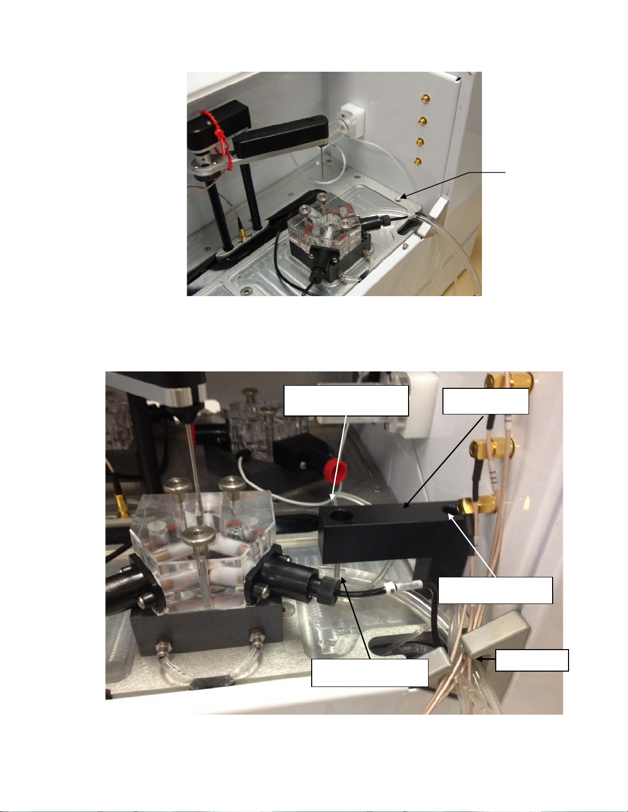
2.2.4.2 YSI 2900 Series Monitor Sample Cup Installation
1. Using a 3/32” Allen hex wrench, remove the screw from the right rear of the 2900 Series deck as shown below
(Figure 2-8). Discard the screw.
Figure 2-7
15
Sample tubing connector
(bottom)
Mounting screw location
(9/64 inch hex screw)
Waste tubing connector
YSI 2900 Monitor
Cup
Tubing port
Remove
screw
Figure 2-8
2. Using a 9/64” Allen hex wrench and the long hex screw provided, mount the Monitor Sample Cup on the 2900
Series deck (Figure 2-9). Ensure the hex screw is securely tightened.
(left side)
Figure 2-9
16
Sample Line
Waste Line
2.2.4.3 Sample and Waste Line Installation
1. Run the sample and waste lines from the Multi-Channel Online Monitor through the tubing port on the side of the
2900 Series Analyzer (Figure 2-9).
2. Connect the waste line to the Monitor Sample Cup by carefully sliding the waste line onto the side connector
(Figure 2-9).
3. Connect the sample line to the Monitor Sample Cup by carefully sliding the sample line onto the bottom
connector (Figure 2-9).
4. Connect the other end of the sample line to the Multi-Channel Online Monitor sample line connection on the
Left side of the peristaltic pump (Figure 2-10).
Figure 2-10
5. Connect the other end of the waste line to the Multi-Channel Online Monitor waste line connection on the Right
side of the peristaltic pump (Figure 2-10).
17
In order to ensure that the YSI 2900 Series data will be displayed in the Multi-Channel Online Monitor
Operations and Mainte nance Manual for changing the YSI 2900 Series date.
2.3 Configuring the Analyzer
The YSI 2900 Series Biochemistry Analyzer must be configured correctly to allow Multi-Channel Online Monitor operation.
The following procedures provide the basic steps to configure the YSI 2900 Series settings. Refer to the YSI 2900 Series
Biochemistry Analyzers Operations and Maintenance Manual for more detailed information.
2.3.1 Programming the RS-232 com munication settings
The YSI 2900 Series RS-232 communication settings must be configured correctly to allow data transmission and remote
control access from the Multi-Channel Online Monitor. The following procedure provides the basic steps to configure the
YSI 2900 Series communication settings. Refer to the YSI 2900 Series Biochemistry Analyzers Operations and
Maintenance Manual for more detailed information
data tab, the date displayed on the YSI 2900 Series Analyzer must match the date shown in the
Multi-Channel Online Monitor software application. If necessary, change the YSI 2900 Series date by
touching the time displayed on the main screen. Refer to the YSI 2900 Series Biochemistry Analyzers
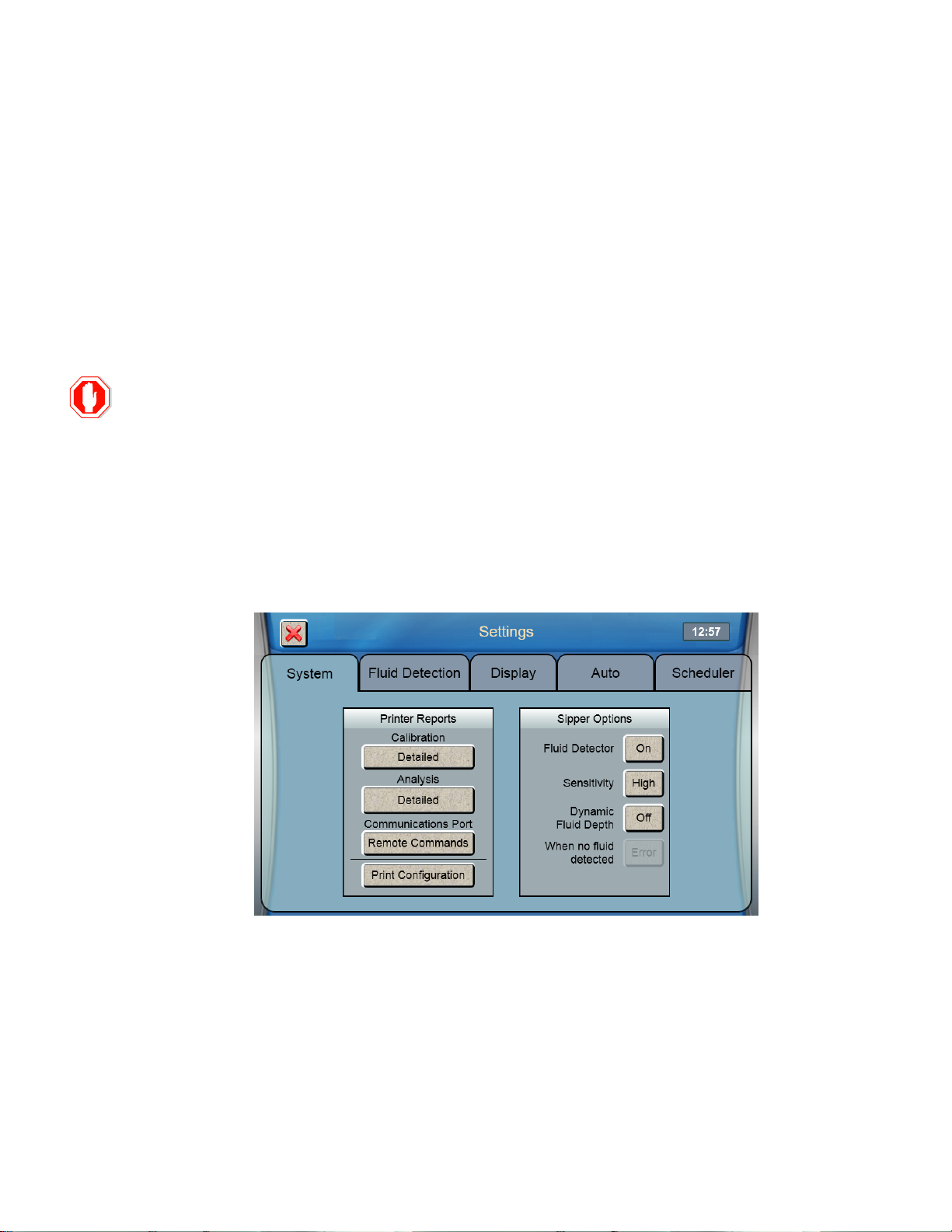
1. From the YSI 2900 Series Touchscreen, select Settings.
2. Select the System tab.
3. Set the Communications Port to Remote Commands.
2.3.2 Bottle Fluid Detection
The 2900 Series bottle fluid detection must be turned On for ALL bottles whenever the Multi-Channel Online
Monitor Bottle Check function is enabled. See Section 4.5.3 Bottle Check.
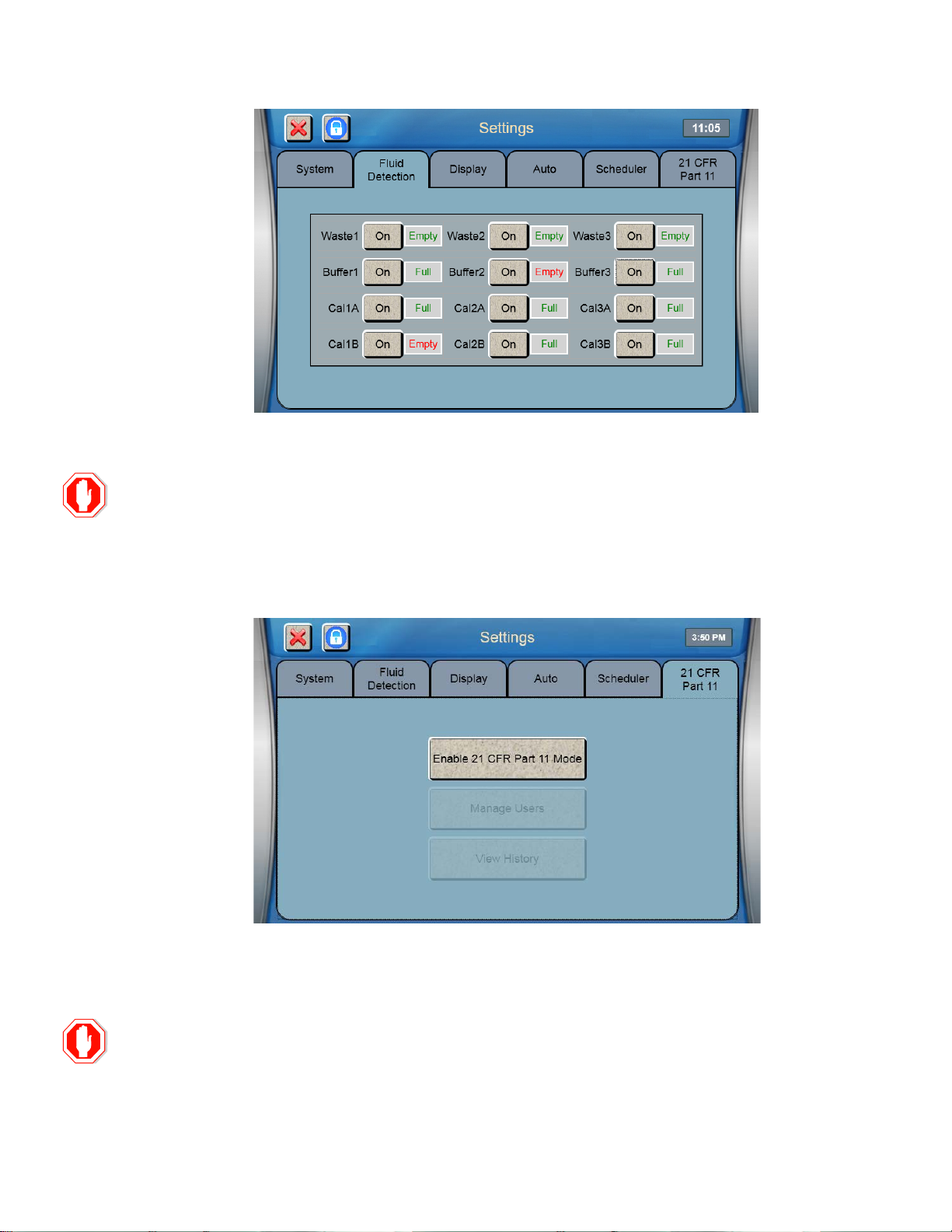
4. Select the Flui d Detection tab.
5. Set ALL bottles to [On].
18
Ensure the 2900 Series analyzer 21 CFR, Part 11 function is disabled. The Multi-Channel Online
2.3.3 21 CFR Part 11
Monitor provides 21 CFR, Part 11, compliance for online monitoring data.
6. Select the 21 CFR Part 11 tab.
7. Disable the 21 CFR Part 11 mode. The screen below shows 21 CFR Part 11 mode is disabled.
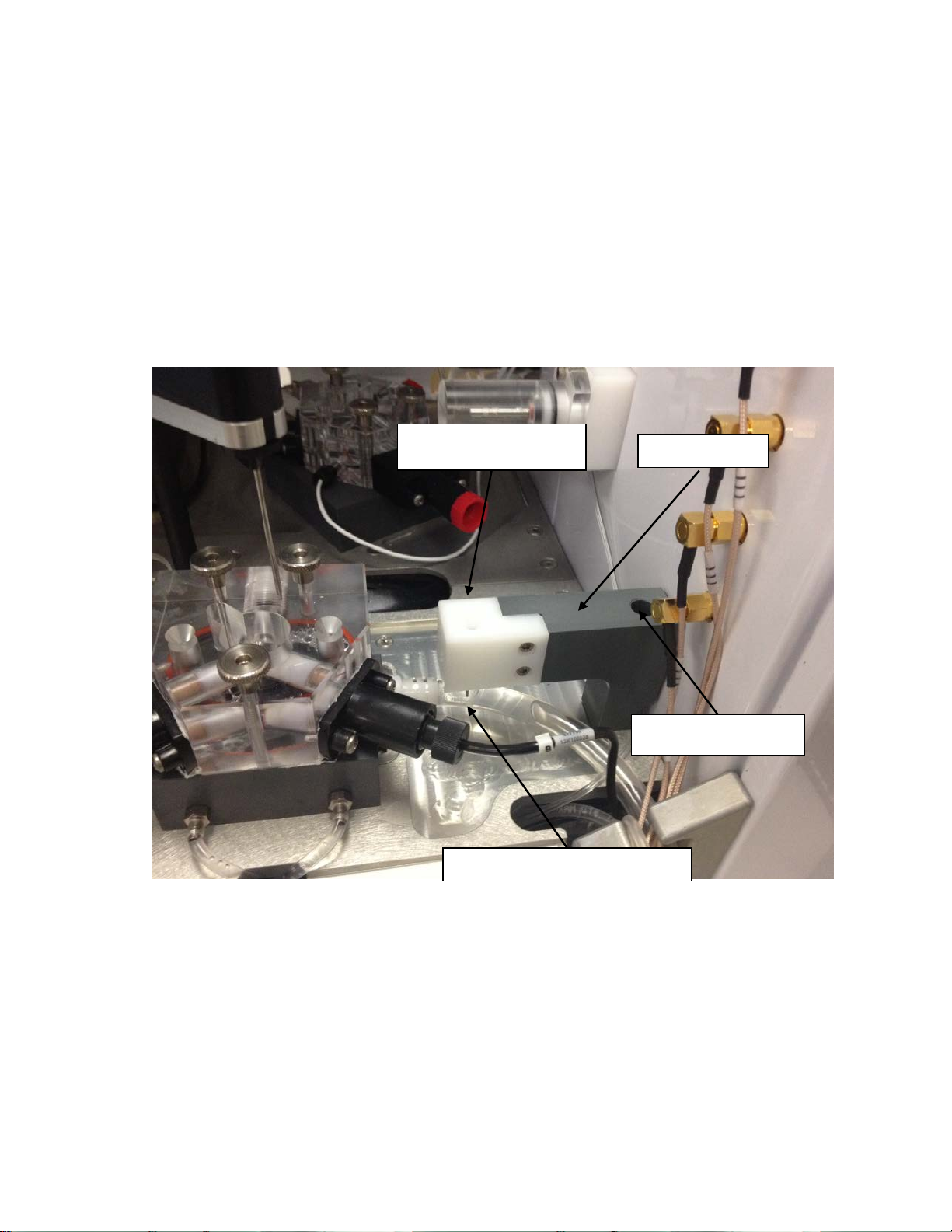
2.3.4 Sipper Alignment
The 2900 Series sipper must be aligned with the monitor sample cup and the depth must be set.
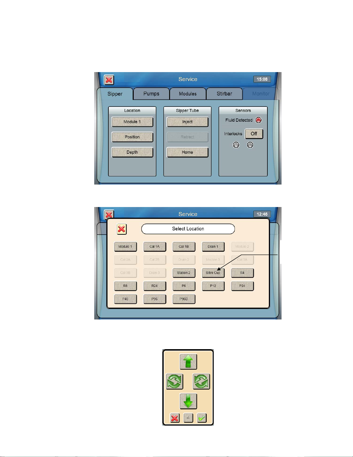
1. From the YSI 2900 Series Touchscreen, select Service.
19
Touch Sitini
2. Select the Sipper tab.
3. Select the Locati on [Module 1] button.
4. Select [Sitini Cup].
Cup
5. The sipper will move to the Monitor Sample Cup and should be centered above the funnel shaped opening in the
top of the cup. If the sipper is not centered, touch
[Position] and use the arrow buttons to center the sipper.
20
Touch
6. Make certain the Sipper is centered, then touch at the bottom right of the adjustment window.
2.3.5 Sipper Depth
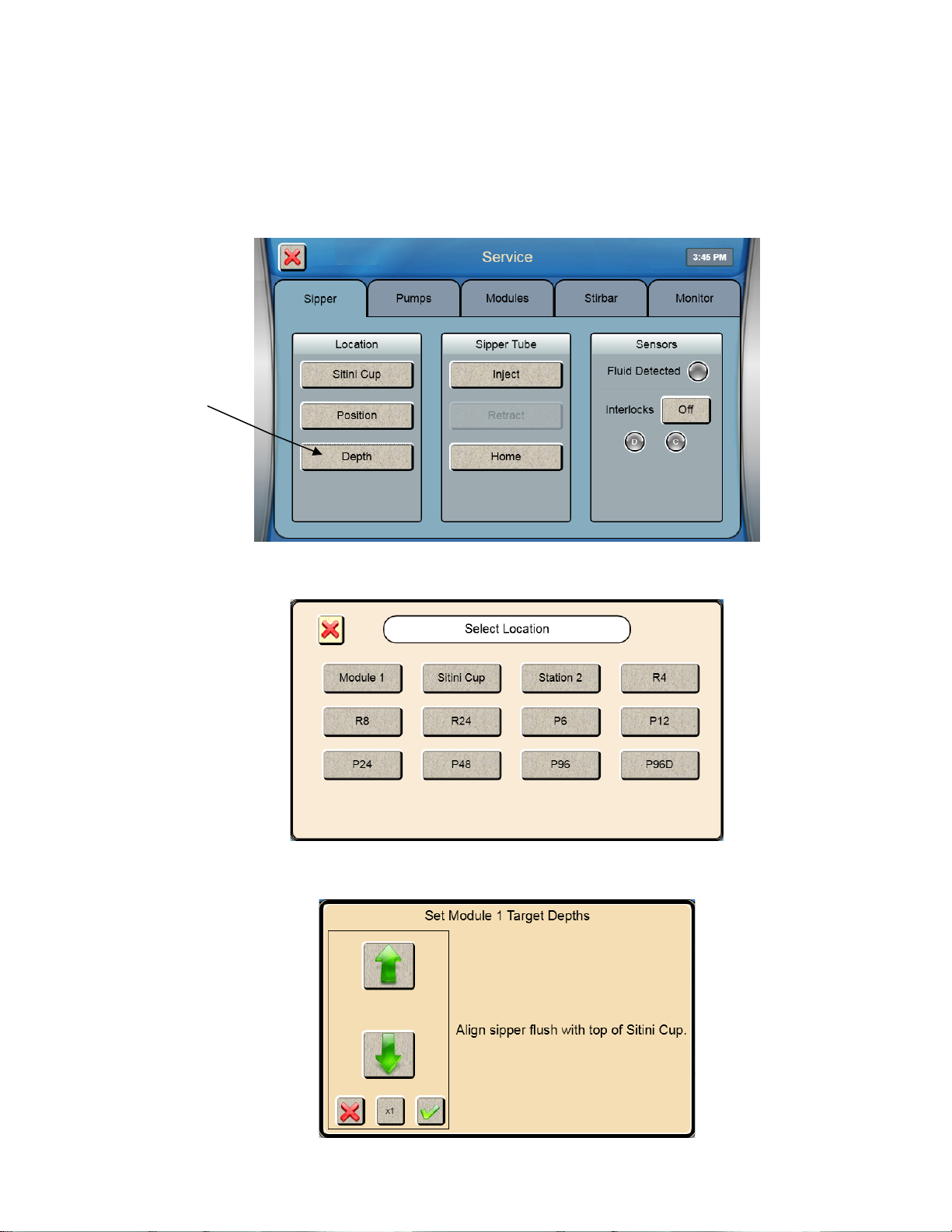
1. Select [Depth].
Depth
2. Select [Sitini Cup].
3. Use the Up and Down Arrow buttons to adjust the sipper so the tip is flush with the top of the Monitor Sam ple Cup.
21

4. Touch at the bottom right of the adjustment window to save the depth setting.
2.4 Connecting Vessels to the Multi-Channel Online Monitor
The FISP Sampling Probe and all tubing assemblies used with the Multi-Channel Online Monitor
are not compatible for vacuum autoclave cycles. Do NOT use any vacuum autoclave cycles when
autoclaving these items. Vacuum cycles include pre-vacuum and post-autoclave vacuum drying
cycles.
2.4.1 Sample Probe Installation
FISP probes allow direct transfer of the vessel contents and provide a sterile barrier for the vessel. The sterile barrier is
obtained through the use of a sterilized 0.2 um ceramic membrane mounted onto the FISP housing (Figure 1-6 & Figure
1-7). FISP sampling probes are available in two models, which are the D-Series and the F-Series sampling probes.
2.4.1.1 Sample Probe Assembly
Refer to the FISP Sampling Probe User Guide for probe assembly.
Wear latex gloves when assembling the probe. Refer to the FISP Sampling Probe User Guide for
assembly, installation, operation and maintenance of the probe.
2.4.1.2
Installing the Sample Probe
1. Insert the assembled FISP sample probe into the bioreactor. The beveled washer and O-ring form a seal between the
probe and vessel (Figure 2-11).
2. Tighten the PG 13.5 nut and remove the black plug from the sample probe.
3. Ensure the FISP probe Luer connector is tightly secured to the FISP probe.
22
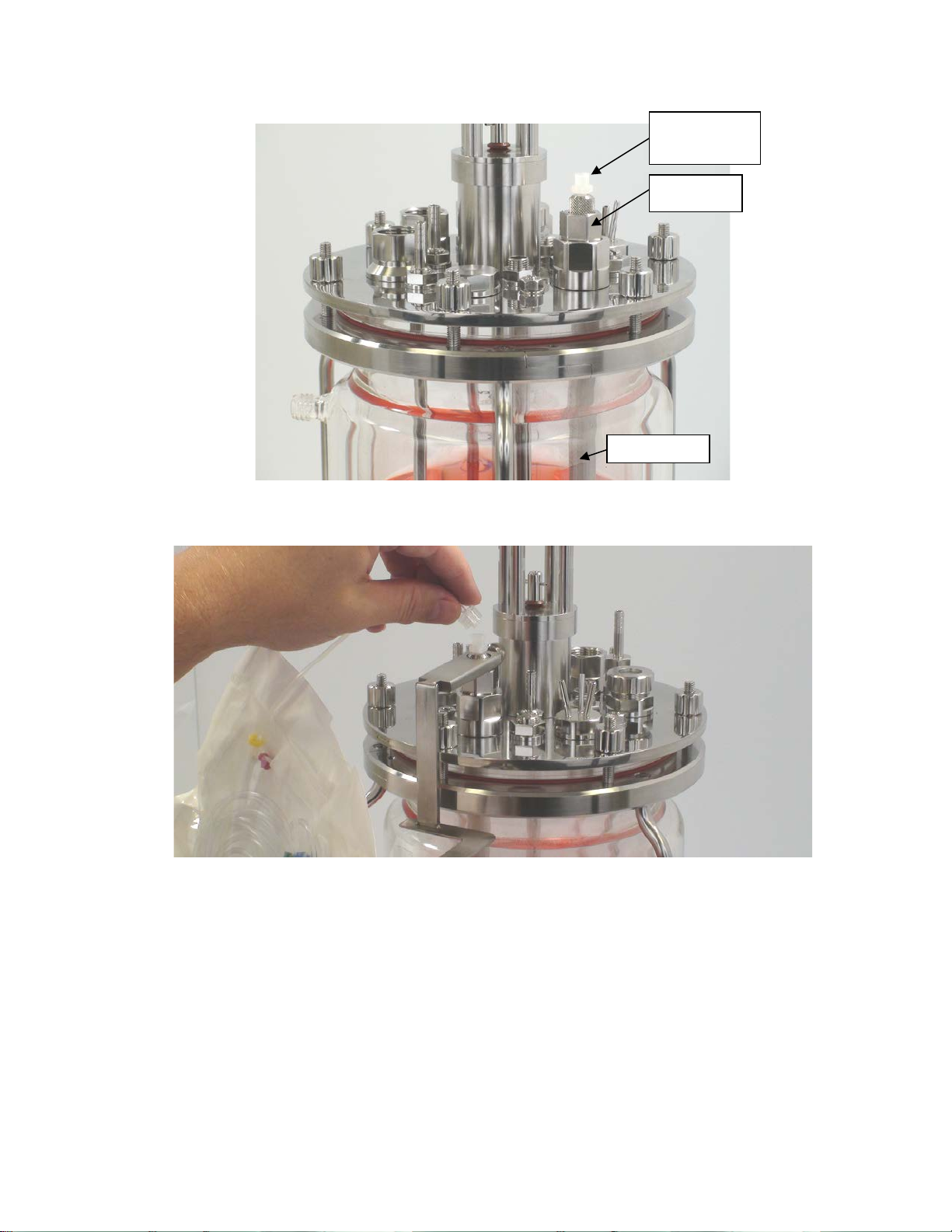
FISP Luer
PG 13.5 Nut
Sample Probe
Figure 2-11
Connector
4. Connect the Multi-Channel Online Monitor sample tubing to the sample probe Luer connector (Figure 2-12).
Figure 2-12
5. Clamp the Pharmed
®
tubing approximately 1 inch (2.5 cm) above the luer connector.
6. If the vessel will be autoclaved, secure the polypropylene bag to the side of the vessel or headplate using autoclave
tape. Ensure that the Multi-Channel Online Monitor sample tubing is not pinched or crimped near the FISP connector.
Figure 2-13 shows the proper position of the sample tubing at the FISP connection.
23
Do NOT use any vacuum autoclave cycles when autoclaving the tubing
Tubing should be straight and not
If the Multi-Channel Online Monitor sample tubing is pinched or crimped, tubing damage may
occur during the autoclave cycle.
pinched or crimped
Figure 2-13
7. Autoclave the bioreactor with the sample probe and Multi-Channel Online Monitor sample tubing assembly.
assembly. Vacuum cycles include pre-vacuum and post-autoclave vacuum
drying cycles.
8. After the autoclave cycle is complete, remove the vessel from the autoclave and allow it to cool to room temperature.
24
 Loading...