

Page 1

IQ SENSOR NET
MIQ/TC 2020 XT
Operating manual
ba76019e01 12/2012
Modular multiparameter measuring system,
Terminal/Controller MIQ/TC 2020 XT
Page 2

MIQ/TC 2020 XT
Note
For the most recent version of the manual, please visit www.ysi.com
.
Up-to-dateness of
instrument software
The continuous development of the instrument software is part of the
consequent improvement process of the instrument software. The
current instrument software for the MIQ/TC 2020 XT is available on the
Internet. It can be transferred to your instrument with the aid of USB
memory device. More detailed information is given on the Internet
under www.ysi.com
.
Saving the password If access control is enabled for the IQ S
administrator password is lost, quick administrator acces to the
IQ S
ENSOR NET is not possible (access control: see section 5.4).
To avoid the loss of the password we recommend to create a back-up
of the administrator password. This also applies to the use of the
electronic key.
To be on the safe side, you can store the administrator password on an
electronic key and/or note it on paper or a PC. Store the passwords in
a safe place.
ENSOR NET and the
Contact YSI
1725 Brannum Lane
Yellow Springs, OH 45387 USA
Tel: +1 937-767-7241
800-765-4974
Email: environmental@ysi.com
Internet: www.ysi.com
Copyright © 2011 Xylem Inc.
2
ba76019e01 12/2012
Page 3

System 2020 XT USB Contents
IQ SENSOR NET System 2020 XT USB - Contents
1 Overview . . . . . . . . . . . . . . . . . . . . . . . . . . . . . . . . . . . . . . . . . . . . . . . . . . . . . . . . . . . 1-1
1.1 How to use this system operating manual . . . . . . . . . . . . . . . . . . . . . . . . . . . . . . . . . . . . 1-1
1.2 The IQ S
1.2.1 Structure of the system . . . . . . . . . . . . . . . . . . . . . . . . . . . . . . . . . . . . . . . . . . . . 1-2
1.2.2 Functions in the IQ S
1.2.3 Possible ways to communicate with the IQ S
1.2.4 Components of the system 2020 XT USB . . . . . . . . . . . . . . . . . . . . . . . . . . . . . . 1-7
1.2.5 MIQ modules . . . . . . . . . . . . . . . . . . . . . . . . . . . . . . . . . . . . . . . . . . . . . . . . . . . 1-10
1.3 MIQ/TC 2020 XT terminal/controller . . . . . . . . . . . . . . . . . . . . . . . . . . . . . . . . . . . . . . . . 1-12
1.3.1 Operation as terminal/controller . . . . . . . . . . . . . . . . . . . . . . . . . . . . . . . . . . . . . 1-13
1.3.2 Operation as a terminal . . . . . . . . . . . . . . . . . . . . . . . . . . . . . . . . . . . . . . . . . . . 1-14
1.3.3 Operation as backup controller . . . . . . . . . . . . . . . . . . . . . . . . . . . . . . . . . . . . . 1-15
1.3.4 USB interface . . . . . . . . . . . . . . . . . . . . . . . . . . . . . . . . . . . . . . . . . . . . . . . . . . . 1-16
1.3.5 Status LED . . . . . . . . . . . . . . . . . . . . . . . . . . . . . . . . . . . . . . . . . . . . . . . . . . . . . 1-17
1.4 Behavior of the IQ S
1.4.1 Behavior of the IQ S
1.4.2 Behavior of the IQ S
1.4.3 Availability of the system . . . . . . . . . . . . . . . . . . . . . . . . . . . . . . . . . . . . . . . . . . 1-19
ENSOR NET system 2020 XT USB . . . . . . . . . . . . . . . . . . . . . . . . . . . . . . . . . . . . 1-2
ENSOR NET . . . . . . . . . . . . . . . . . . . . . . . . . . . . . . . . . . . . . 1-4
ENSOR NET . . . . . . . . . . . . . . . . . . . 1-5
ENSOR NET in case of error . . . . . . . . . . . . . . . . . . . . . . . . . . . . . . . 1-18
ENSOR NET in case of power failure . . . . . . . . . . . . . . . . . . 1-18
ENSOR NET if a components fails . . . . . . . . . . . . . . . . . . . . 1-18
2 Safety instructions . . . . . . . . . . . . . . . . . . . . . . . . . . . . . . . . . . . . . . . . . . . . . . . . . . . 2-1
2.1 User qualification . . . . . . . . . . . . . . . . . . . . . . . . . . . . . . . . . . . . . . . . . . . . . . . . . . . . . . . . 2-1
2.2 Authorized use . . . . . . . . . . . . . . . . . . . . . . . . . . . . . . . . . . . . . . . . . . . . . . . . . . . . . . . . . 2-2
2.3 General safety instructions . . . . . . . . . . . . . . . . . . . . . . . . . . . . . . . . . . . . . . . . . . . . . . . . 2-2
3 Installation . . . . . . . . . . . . . . . . . . . . . . . . . . . . . . . . . . . . . . . . . . . . . . . . . . . . . . . . . . 3-1
3.1 Scopes of delivery . . . . . . . . . . . . . . . . . . . . . . . . . . . . . . . . . . . . . . . . . . . . . . . . . . . . . . . 3-1
3.1.1 MIQ modules . . . . . . . . . . . . . . . . . . . . . . . . . . . . . . . . . . . . . . . . . . . . . . . . . . . . 3-1
3.1.2 Terminal/Controller . . . . . . . . . . . . . . . . . . . . . . . . . . . . . . . . . . . . . . . . . . . . . . . . 3-1
3.2 Requirements of the measurement location . . . . . . . . . . . . . . . . . . . . . . . . . . . . . . . . . . . 3-1
3.3 System planning . . . . . . . . . . . . . . . . . . . . . . . . . . . . . . . . . . . . . . . . . . . . . . . . . . . . . . . . 3-2
3.4 Basic requirements for optimum installation . . . . . . . . . . . . . . . . . . . . . . . . . . . . . . . . . . . 3-3
3.4.1 General information . . . . . . . . . . . . . . . . . . . . . . . . . . . . . . . . . . . . . . . . . . . . . . . 3-3
3.4.2 Drawing up the power rating . . . . . . . . . . . . . . . . . . . . . . . . . . . . . . . . . . . . . . . . 3-3
3.4.3 Effect of the cable length . . . . . . . . . . . . . . . . . . . . . . . . . . . . . . . . . . . . . . . . . . . 3-6
3.4.4 Optimum installation of MIQ power supply modules . . . . . . . . . . . . . . . . . . . . . 3-10
3.4.5 Installation guidelines for lightning protection . . . . . . . . . . . . . . . . . . . . . . . . . . 3-10
3.5 Connecting system components . . . . . . . . . . . . . . . . . . . . . . . . . . . . . . . . . . . . . . . . . . . 3-13
3.5.1 General information . . . . . . . . . . . . . . . . . . . . . . . . . . . . . . . . . . . . . . . . . . . . . . 3-13
3.5.2 Stacked mounting of MIQ modules: . . . . . . . . . . . . . . . . . . . . . . . . . . . . . . . . . . 3-14
3.5.3 Distributed mounting of MIQ modules . . . . . . . . . . . . . . . . . . . . . . . . . . . . . . . . 3-21
ba76019e01 12/2012
0 - 1
Page 4

Contents System 2020 XT USB
3.5.4 Connecting IQ sensors . . . . . . . . . . . . . . . . . . . . . . . . . . . . . . . . . . . . . . . . . . . .3-25
3.5.5 Installing terminal components . . . . . . . . . . . . . . . . . . . . . . . . . . . . . . . . . . . . . .3-27
3.6 Installation of the MIQ modules at the installation location . . . . . . . . . . . . . . . . . . . . . . .3-29
3.6.1 General information . . . . . . . . . . . . . . . . . . . . . . . . . . . . . . . . . . . . . . . . . . . . . .3-29
3.6.2 Mounting on a mounting stand with the SSH/IQ sun shield . . . . . . . . . . . . . . . .3-30
3.6.3 Mounting under the SD/K 170 sun shield . . . . . . . . . . . . . . . . . . . . . . . . . . . . . .3-32
3.6.4 Panel mounting . . . . . . . . . . . . . . . . . . . . . . . . . . . . . . . . . . . . . . . . . . . . . . . . .3-34
3.6.5 Top hat rail mounting . . . . . . . . . . . . . . . . . . . . . . . . . . . . . . . . . . . . . . . . . . . . .3-36
3.7 Electrical connections: General instructions . . . . . . . . . . . . . . . . . . . . . . . . . . . . . . . . . .3-37
3.8 Connecting the voltage supply . . . . . . . . . . . . . . . . . . . . . . . . . . . . . . . . . . . . . . . . . . . . .3-39
3.9 Commissioning . . . . . . . . . . . . . . . . . . . . . . . . . . . . . . . . . . . . . . . . . . . . . . . . . . . . . . . .3-39
3.9.1 Topology and terminator switch . . . . . . . . . . . . . . . . . . . . . . . . . . . . . . . . . . . . .3-39
3.9.2 Start checklist and system start . . . . . . . . . . . . . . . . . . . . . . . . . . . . . . . . . . . . .3-42
3.9.3 Checking the voltage supply . . . . . . . . . . . . . . . . . . . . . . . . . . . . . . . . . . . . . . . .3-45
3.10 System extension and modification . . . . . . . . . . . . . . . . . . . . . . . . . . . . . . . . . . . . . . . . .3-47
3.10.1 General information . . . . . . . . . . . . . . . . . . . . . . . . . . . . . . . . . . . . . . . . . . . . . .3-47
3.11 Configuration of the MIQ/TC 2020 XT as a terminal/controller or terminal . . . . . . . . . . .3-48
4 Operation . . . . . . . . . . . . . . . . . . . . . . . . . . . . . . . . . . . . . . . . . . . . . . . . . . . . . . . . . . . 4-1
4.1 MIQ/TC 2020 XT terminal/controllers . . . . . . . . . . . . . . . . . . . . . . . . . . . . . . . . . . . . . . . .4-1
4.1.1 Overview of the operating elements . . . . . . . . . . . . . . . . . . . . . . . . . . . . . . . . . . .4-2
4.1.2 Display . . . . . . . . . . . . . . . . . . . . . . . . . . . . . . . . . . . . . . . . . . . . . . . . . . . . . . . . .4-3
4.1.3 Keys . . . . . . . . . . . . . . . . . . . . . . . . . . . . . . . . . . . . . . . . . . . . . . . . . . . . . . . . . . .4-5
4.1.4 Arrow keys . . . . . . . . . . . . . . . . . . . . . . . . . . . . . . . . . . . . . . . . . . . . . . . . . . . . . .4-5
4.2 General operating principles . . . . . . . . . . . . . . . . . . . . . . . . . . . . . . . . . . . . . . . . . . . . . . .4-6
4.2.1 Navigating in menus, lists and tables . . . . . . . . . . . . . . . . . . . . . . . . . . . . . . . . . .4-7
4.2.2 Entering texts or numerals . . . . . . . . . . . . . . . . . . . . . . . . . . . . . . . . . . . . . . . . . .4-8
4.3 Access to the IQ S
4.3.1 Simple access control . . . . . . . . . . . . . . . . . . . . . . . . . . . . . . . . . . . . . . . . . . . . .4-11
4.3.2 Extended access control . . . . . . . . . . . . . . . . . . . . . . . . . . . . . . . . . . . . . . . . . . .4-12
4.3.3 Extended access control with instrument block . . . . . . . . . . . . . . . . . . . . . . . . .4-13
4.4 Display of current measured values . . . . . . . . . . . . . . . . . . . . . . . . . . . . . . . . . . . . . . . .4-14
4.4.1 Displaying a single measured value . . . . . . . . . . . . . . . . . . . . . . . . . . . . . . . . . .4-15
4.4.2 Displaying four measured values . . . . . . . . . . . . . . . . . . . . . . . . . . . . . . . . . . . .4-15
4.4.3 Displaying eight measured values . . . . . . . . . . . . . . . . . . . . . . . . . . . . . . . . . . .4-16
4.4.4 Displaying recorded measured values . . . . . . . . . . . . . . . . . . . . . . . . . . . . . . . .4-17
4.4.5 Display of the measured values of a measurement location or of all
IQ sensors in the system . . . . . . . . . . . . . . . . . . . . . . . . . . . . . . . . . . . . . . . . . .4-19
4.5 Messages and log book . . . . . . . . . . . . . . . . . . . . . . . . . . . . . . . . . . . . . . . . . . . . . . . . . .4-20
4.5.1 Message types . . . . . . . . . . . . . . . . . . . . . . . . . . . . . . . . . . . . . . . . . . . . . . . . . .4-20
4.5.2 Log book . . . . . . . . . . . . . . . . . . . . . . . . . . . . . . . . . . . . . . . . . . . . . . . . . . . . . . .4-20
4.5.3 Viewing detailed message texts . . . . . . . . . . . . . . . . . . . . . . . . . . . . . . . . . . . . .4-23
4.5.4 Acknowledge all messages . . . . . . . . . . . . . . . . . . . . . . . . . . . . . . . . . . . . . . . .4-24
4.6 Calibration data . . . . . . . . . . . . . . . . . . . . . . . . . . . . . . . . . . . . . . . . . . . . . . . . . . . . . . . .4-25
4.6.1 Calibration entries in the log book . . . . . . . . . . . . . . . . . . . . . . . . . . . . . . . . . . .4-25
4.6.2 Calibration history . . . . . . . . . . . . . . . . . . . . . . . . . . . . . . . . . . . . . . . . . . . . . . . .4-26
4.7 Status info of sensors and outputs . . . . . . . . . . . . . . . . . . . . . . . . . . . . . . . . . . . . . . . . .4-27
ENSOR NET with enabled access control . . . . . . . . . . . . . . . . . . . . . .4-11
0 - 2
ba76019e01 12/2012
Page 5

System 2020 XT USB Contents
4.8 General course when calibrating, cleaning, servicing or repairing an IQ sensor . 4-28
4.8.1 Maintenance condition of IQ sensors . . . . . . . . . . . . . . . . . . . . . . . . . . . . . . . . . 4-29
4.8.2 Switching on the maintenance condition . . . . . . . . . . . . . . . . . . . . . . . . . . . . . . 4-30
4.8.3 Switching off the maintenance condition . . . . . . . . . . . . . . . . . . . . . . . . . . . . . . 4-31
4.9 Data exchange via the USB interface . . . . . . . . . . . . . . . . . . . . . . . . . . . . . . . . . . . . . . . 4-32
4.9.1 Saving IQ S
ENSOR NET data on a USB memory device . . . . . . . . . . . . . . . . . . . 4-32
4.9.2 Transmitting recorded measurement data to a PC . . . . . . . . . . . . . . . . . . . . . . 4-34
4.9.3 Manual backup of the system configuration . . . . . . . . . . . . . . . . . . . . . . . . . . . . 4-35
4.9.4 Restoring the system configuration . . . . . . . . . . . . . . . . . . . . . . . . . . . . . . . . . . 4-35
4.10 Software update for IQ S
ENSOR NET components . . . . . . . . . . . . . . . . . . . . . . . . . . . . . . 4-37
4.10.1 Information on software versions . . . . . . . . . . . . . . . . . . . . . . . . . . . . . . . . . . . . 4-38
4.11 MIQ/TC 2020 XT in its function as terminal and backup controller . . . . . . . . . . . . . . . . . 4-39
5 Settings/setup . . . . . . . . . . . . . . . . . . . . . . . . . . . . . . . . . . . . . . . . . . . . . . . . . . . . . . . 5-1
5.1 Selecting the language . . . . . . . . . . . . . . . . . . . . . . . . . . . . . . . . . . . . . . . . . . . . . . . . . . .5-1
5.2 Configuration of the MIQ/TC 2020 XT . . . . . . . . . . . . . . . . . . . . . . . . . . . . . . . . . . . . . . . . 5-2
5.3 Terminal settings . . . . . . . . . . . . . . . . . . . . . . . . . . . . . . . . . . . . . . . . . . . . . . . . . . . . . . . . 5-3
5.4 Access control . . . . . . . . . . . . . . . . . . . . . . . . . . . . . . . . . . . . . . . . . . . . . . . . . . . . . . . . . . 5-5
5.4.1 Simple access control (Unlock/lock settings) . . . . . . . . . . . . . . . . . . . . . . . . . . . . 5-6
5.4.2 Extended access control . . . . . . . . . . . . . . . . . . . . . . . . . . . . . . . . . . . . . . . . . . . 5-8
5.4.3 Instrument block . . . . . . . . . . . . . . . . . . . . . . . . . . . . . . . . . . . . . . . . . . . . . . . . . 5-10
5.4.4 Electronic key . . . . . . . . . . . . . . . . . . . . . . . . . . . . . . . . . . . . . . . . . . . . . . . . . . . 5-10
5.5 Editing the list of sensors . . . . . . . . . . . . . . . . . . . . . . . . . . . . . . . . . . . . . . . . . . . . . . . . 5-12
5.5.1 Entering / editing a name for an IQ sensor . . . . . . . . . . . . . . . . . . . . . . . . . . . . 5-12
5.5.2 Changing the display position . . . . . . . . . . . . . . . . . . . . . . . . . . . . . . . . . . . . . . 5-13
5.5.3 Erasing inactive sensor datasets . . . . . . . . . . . . . . . . . . . . . . . . . . . . . . . . . . . . 5-14
5.6 Setting up IQ sensors/differential sensors . . . . . . . . . . . . . . . . . . . . . . . . . . . . . . . . . . . 5-15
5.6.1 Creating a differential sensor . . . . . . . . . . . . . . . . . . . . . . . . . . . . . . . . . . . . . . . 5-15
5.6.2 Erasing a differential sensor . . . . . . . . . . . . . . . . . . . . . . . . . . . . . . . . . . . . . . . . 5-16
5.6.3 Adjusting the settings for sensors/differential sensors . . . . . . . . . . . . . . . . . . . . 5-17
5.7 Sensor-sensor link
(automatic inclusion of an influence quantity) . . . . . . . . . . . . . . . . . . . . . . . . . . . . . . . . . 5-18
5.7.1 Establishing a sensor-sensor link . . . . . . . . . . . . . . . . . . . . . . . . . . . . . . . . . . . . 5-19
5.7.2 Erasing a Sensor-sensor link . . . . . . . . . . . . . . . . . . . . . . . . . . . . . . . . . . . . . . . 5-22
5.8 Editing the list of outputs . . . . . . . . . . . . . . . . . . . . . . . . . . . . . . . . . . . . . . . . . . . . . . . . .5-23
5.8.1 Entering / editing the name of an output . . . . . . . . . . . . . . . . . . . . . . . . . . . . . . 5-23
5.8.2 Erasing an inactive dataset for an MIQ output module . . . . . . . . . . . . . . . . . . . 5-24
5.8.3 Output links/settings . . . . . . . . . . . . . . . . . . . . . . . . . . . . . . . . . . . . . . . . . . . . . . 5-25
5.9 Settings for a measurement location . . . . . . . . . . . . . . . . . . . . . . . . . . . . . . . . . . . . . . . . 5-26
5.10 Alarm settings . . . . . . . . . . . . . . . . . . . . . . . . . . . . . . . . . . . . . . . . . . . . . . . . . . . . . . . . . 5-28
5.10.1 General information . . . . . . . . . . . . . . . . . . . . . . . . . . . . . . . . . . . . . . . . . . . . . . 5-28
5.10.2 Setting up / editing alarms . . . . . . . . . . . . . . . . . . . . . . . . . . . . . . . . . . . . . . . . . 5-29
5.10.3 Alarm output to display . . . . . . . . . . . . . . . . . . . . . . . . . . . . . . . . . . . . . . . . . . . . 5-32
5.10.4 Alarm output as relay action . . . . . . . . . . . . . . . . . . . . . . . . . . . . . . . . . . . . . . . . 5-33
5.10.5 Alarm message as an SMS . . . . . . . . . . . . . . . . . . . . . . . . . . . . . . . . . . . . . . . . 5-33
5.11 System settings . . . . . . . . . . . . . . . . . . . . . . . . . . . . . . . . . . . . . . . . . . . . . . . . . . . . . . . . 5-34
ba76019e01 12/2012
0 - 3
Page 6

Contents System 2020 XT USB
5.11.1 Setting the date and time . . . . . . . . . . . . . . . . . . . . . . . . . . . . . . . . . . . . . . . . . .5-34
5.11.2 Site altitude / setting the medium air pressure . . . . . . . . . . . . . . . . . . . . . . . . . .5-35
5.12 Measured value logging . . . . . . . . . . . . . . . . . . . . . . . . . . . . . . . . . . . . . . . . . . . . . . . . . .5-36
5.12.1 Setting the recording interval (dt) and recording duration (Dur.) . . . . . . . . . . . . .5-37
6 Maintenance and cleaning . . . . . . . . . . . . . . . . . . . . . . . . . . . . . . . . . . . . . . . . . . . . . 6-1
6.1 Maintenance . . . . . . . . . . . . . . . . . . . . . . . . . . . . . . . . . . . . . . . . . . . . . . . . . . . . . . . . . . .6-1
6.2 Cleaning . . . . . . . . . . . . . . . . . . . . . . . . . . . . . . . . . . . . . . . . . . . . . . . . . . . . . . . . . . . . . . .6-1
7 What to do if ... . . . . . . . . . . . . . . . . . . . . . . . . . . . . . . . . . . . . . . . . . . . . . . . . . . . . . . 7-1
7.1 Information on errors . . . . . . . . . . . . . . . . . . . . . . . . . . . . . . . . . . . . . . . . . . . . . . . . . . . . .7-1
7.2 Diagnosing faults in the voltage supply . . . . . . . . . . . . . . . . . . . . . . . . . . . . . . . . . . . . . . .7-1
7.2.1 Options for checking the voltage . . . . . . . . . . . . . . . . . . . . . . . . . . . . . . . . . . . . .7-1
7.2.2 Measuring the voltage . . . . . . . . . . . . . . . . . . . . . . . . . . . . . . . . . . . . . . . . . . . . .7-2
7.2.3 Tips for clearing errors in the voltage supply . . . . . . . . . . . . . . . . . . . . . . . . . . . .7-4
7.3 Other errors . . . . . . . . . . . . . . . . . . . . . . . . . . . . . . . . . . . . . . . . . . . . . . . . . . . . . . . . . . . .7-6
7.4 Replacing system components . . . . . . . . . . . . . . . . . . . . . . . . . . . . . . . . . . . . . . . . . . . . .7-8
7.4.1 Replacing passive components . . . . . . . . . . . . . . . . . . . . . . . . . . . . . . . . . . . . . .7-8
7.4.2 Adding and replacing IQ sensors . . . . . . . . . . . . . . . . . . . . . . . . . . . . . . . . . . . . .7-8
7.4.3 Adding and replacing MIQ output modules . . . . . . . . . . . . . . . . . . . . . . . . . . . . .7-12
8 Technical data . . . . . . . . . . . . . . . . . . . . . . . . . . . . . . . . . . . . . . . . . . . . . . . . . . . . . . . 8-1
8.1 General system data . . . . . . . . . . . . . . . . . . . . . . . . . . . . . . . . . . . . . . . . . . . . . . . . . . . . .8-1
8.2 General data of MIQ modules . . . . . . . . . . . . . . . . . . . . . . . . . . . . . . . . . . . . . . . . . . . . . .8-4
8.3 MIQ/TC 2020 XT terminal/controller . . . . . . . . . . . . . . . . . . . . . . . . . . . . . . . . . . . . . . . . .8-6
8.4 Space required by mounted components . . . . . . . . . . . . . . . . . . . . . . . . . . . . . . . . . . . . .8-7
9 Contact Information . . . . . . . . . . . . . . . . . . . . . . . . . . . . . . . . . . . . . . . . . . . . . . . . . . 9-1
9.1 Ordering & Technical Support . . . . . . . . . . . . . . . . . . . . . . . . . . . . . . . . . . . . . . . . . . . . . .9-1
9.2 Service Information . . . . . . . . . . . . . . . . . . . . . . . . . . . . . . . . . . . . . . . . . . . . . . . . . . . . . .9-1
10 Accessories and options . . . . . . . . . . . . . . . . . . . . . . . . . . . . . . . . . . . . . . . . . . . . . 10-1
11 Indexes . . . . . . . . . . . . . . . . . . . . . . . . . . . . . . . . . . . . . . . . . . . . . . . . . . . . . . . . . . . . 11-1
11.1 Index of all displays . . . . . . . . . . . . . . . . . . . . . . . . . . . . . . . . . . . . . . . . . . . . . . . . . . . . .12-1
11.2 Explanation of the message codes . . . . . . . . . . . . . . . . . . . . . . . . . . . . . . . . . . . . . . . . .10-2
11.2.1 Error messages . . . . . . . . . . . . . . . . . . . . . . . . . . . . . . . . . . . . . . . . . . . . . . . . .10-2
11.2.2 Info messages . . . . . . . . . . . . . . . . . . . . . . . . . . . . . . . . . . . . . . . . . . . . . . . . . .10-3
11.3 Index . . . . . . . . . . . . . . . . . . . . . . . . . . . . . . . . . . . . . . . . . . . . . . . . . . . . . . . . . . . . . . . .10-4
12 Appendix . . . . . . . . . . . . . . . . . . . . . . . . . . . . . . . . . . . . . . . . . . . . . . . . . . . . . . . . . . 11-1
12.1 Forgotten the password? (store separately if required) . . . . . . . . . . . . . . . . . . . . . . . . . .11-1
12.2 Default password . . . . . . . . . . . . . . . . . . . . . . . . . . . . . . . . . . . . . . . . . . . . . . . . . . . . . . .11-2
0 - 4
ba76019e01 12/2012
Page 7
System 2020 XT USB Overview
IQ Sensor Net Operating Manual
System
Operating
Manual
(Ring Binder)
IQ Sensor
Operating
Manual
MIQ Module
Operating
Manual
MIQ Terminal
Operating
Manual
Component Operating Manuals
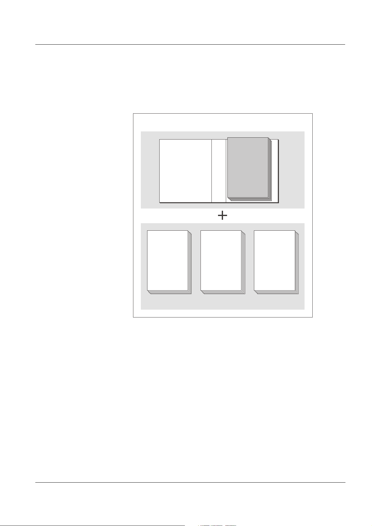
1Overview
1.1 How to use this system operating manual
Structure of the
ENSOR NET
IQ S
operating manual
ba76019e01 12/2012
Fig. 1-1 Structure of the IQ SENSOR NET operating manual
The IQ SENSOR NET operating manual has a modular structure like the
IQ S
ENSOR NET system itself. It consists of this system operating
manual and the operating manuals of all the components used.
The space in the ring binder behind the system operating manual is
intended for filing the component operating manuals. Please file all
component operating manuals here so that all information is quickly
available in one location.
1 - 1
Page 8

Overview System 2020 XT USB
1.2 The IQ SENSOR NET system 2020 XT USB
1.2.1 Structure of the system
The IQ S
ENSOR NET is a modular measuring system for online analysis.
Modular means that the essential functional units of the measuring
system are distributed in components that can be individually compiled
for special applications.
The essential functional units of the IQ S
ENSOR NET
system 2020 XT USB include:
Terminal/controller
IQ sensors
Inputs (current inputs)
Outputs (relay contacts, current outputs, valve outputs)
Additional terminals (mobile terminals, software terminal)
Help functions (e.g. power supply unit).
System communication The functional units are connected with one another via a common line
(Fig. 1-2). The line consists of two wires and a shield. It transports
digital information between the controller and the other modules. At the
same time, the line is used to supply all modules with electrical voltage
from a power supply unit. The power supply unit is only required for the
power supply and is not used in the system communication.
1 - 2
ba76019e01 12/2012
Page 9
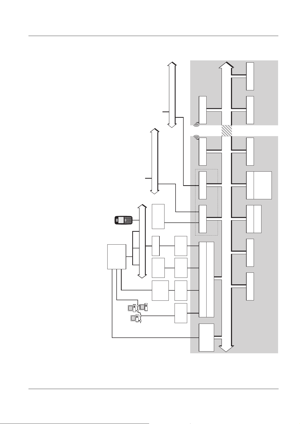
System 2020 XT USB Overview
IQ Sensor
IQ Sensor Net
USB
Memory
Modem
Terminal
IQ SENSOR NET Island 1 IQ SENSOR NET Island 2
Eingänge
mA
mA
RS 232
Adapter
Data
Transfer
Modbus
SPSSPS
SPS
PROFIBUS
IQ Sensor Terminal
MIQ/(A)-PR
MIQ/(A)-MOD
Network
RS 232
Adapter
Ethernet
adapter
MIQ/IF232
PC+
IQ Software
Pack
(Diagnostics and
service only)
Mobile
phone
IQ Sensor Net (Data+Energy)
Radio moduleRadio module
Radio
100 m
Power supplyOutputs
Relay
mA
Valve
Inputs
RS 485
Device
Land line / GSM / Radio / SMS
Null
modem
cable
USB Interface
Terminal/Controller
Interface
modules
ba76019e01 12/2012
Fig. 1-2 Functional units of the IQ SENSOR NET System 2020 XT USB
1 - 3
Page 10

Overview System 2020 XT USB
1.2.2 Functions in the IQ SENSOR NET
The functions of the IQ SENSOR NET are provided by the system
(controller) and the retrofitting components. Details on the functions
listed can be found in the relevant system or components operating
manuals.
Function Component
Alarm messages System
Analog output Current output module
Data logging System
Data recording (PC) IQ software pack
Data transmission (PC) IQ software pack
Data backup on USB memory device MIQ/TC 2020 XT
Data communication (Profibus) MIQ/(A)-PR
Data communication (Modbus) MIQ/(A)-MOD
Remote data transmission (modem) MIQ/TC 2020 XT + USB RS232 adapter
Datalogger IQ software pack
Data server IQ software pack
Differential sensor System
Frequency output Relay output module
Limit monitor Relay output module
Calibration history System
List of outputs, list of sensors System
Log book System
Log book (messages from components) IQ sensor
Output module
Measured value representation (4 types) System
Password System
PID controller Current output module
Pulse-width output Relay output module
1 - 4
Sensor cleaning Relay output module
Valve module
Local settings System
Daily, weekly, monthly load diagram System
Monitoring functions (sensors, system) Output module
Access control System
ba76019e01 12/2012
Page 11

System 2020 XT USB Overview
1.2.3 Possible ways to communicate with the IQ SENSOR NET
Digital communication The IQ SENSOR NET can communicate with humans and machines via
different interfaces.
The following page provides an overview:
Current and relay
interfaces
who can communicate with the IQ S
ENSOR NET
what interfaces and components are required for this
which functions are available with which interface
In addition to the digital communication, output modules provide relay
and current outputs. These can be used for control, feedback control
and monitoring functions.
ba76019e01 12/2012
1 - 5
Page 12

Overview System 2020 XT USB
Available
functions
Who communicates
with the IQ Sensor Net
via which interface/
component
Direct
actions
via the
terminal
user
interface
Viewing/transmitting
current data:
–Measured
values
– Status info
–Alarm
messages
Human
Terminal/controller
X X X X X
MIQ/TC 2020 XT
+ USB memory device
Human + PC
MIQ/IF232
X X X X X
+ IQ software pack
MIQ/TC 2020 XT
X X X X X
+ USB RS232 adapter
+ null modem cable
+ IQ software pack
Human + PC + modem
MIQ/TC 2020 XT
X X X X X
+ USB RS232 adapter
+ modem (analog, GSM, or
radio)
+ IQ software pack
Human + PC/mobile phone
+ modem
MIQ/TC 2020 XT
+ USB RS232 adapter
+ GSM modem
communication via SMS
PROFIBUS DP-V1
MIQ/(A-)PR X
Modbus
MIQ/(A-)MOD;
Modbus RTU operation
MIQ/(A-)MOD;
Point-to-point communication
via RS485
Network (TCP/IP)
MIQ/TC 2020 XT
X X X X X
+ USB Ethernet adapter
Client + Server + PC
("data logger")
MIQ/IF232
+ IQ software pack
(+ network)
Viewing/transmitting
logged data:
–Measured
values
–Measured
System configuration,
–save
/
load
–view
–print
Calibration data,
view
transmit
value
status
X
X
X
X X
/
1 - 6
ba76019e01 12/2012
Page 13

System 2020 XT USB Overview
Each main measured value occupies a sensor location in the
IQ S
ENSOR NET. A double sensor with two active main measured
values thus occupies two sensor locations. The available sensor
locations can be occupied by any single or double sensors.
1.2.4 Components of the system 2020 XT USB
Minimum configuration
(basic components)
IQ sensors, main and
secondary measured
values
The following basic components are required for a 2020 XT USB
system:
An MIQ/TC 2020 XT, configured as controller
A power supply module (e.g. MIQ/PS)
At least one IQ sensor.
Sensors provide main measured values (e.g. pH, D. O. concentration,
turbidity value...) and additionally, depending on the type, secondary
measured values (e.g. temperature). In the System 2020 XT USB,
digital YSI single sensors and double sensors can be used:
Single sensors provide a main measured value and normally a
secondary measured value (example: TriOxmatic 700 IQ
→ D. O. +
temperature).
All active 0/4-20 mA inputs of the MIQ/IC2 input module rank among
the single sensors. Via a 0/4-20 mA input, any external instruments
can be connected to the IQ S
ENSOR NET via their current output.
Each input provides a main measured value.
Double sensors provide up to two main measured values and
normally a secondary measured value (example: VARiON 700 IQ
→ ammonium + nitrate + temperature).
Extension components The system can be adapted to fulfill different specifications by adding
further components, e.g. by:
Terminals. They are the operation and communication units for the
IQ S
ENSOR NET. Available are:
– MIQ/TC 2020 XT for operation of the system from various
locations, e.g. calibration of IQ sensors on site (compatible
terminals, see section 1.4)
– MIQ/T2020 PC software terminals. The connection to the PC can
be established with the MIQ/IF232 interface module and the
RS 232 interface of the PC or a remote connection with a modem
(set for radio transmission, see chapter 10).
Output modules with relay, current and valve outputs. Valve outputs
enable the time controlled, compressed air operated cleaning of the
sensor.
ba76019e01 12/2012
1 - 7
Page 14

Overview System 2020 XT USB
Each current output, relay output and valve output occupies an
output channel in the IQ S
ENSOR NET. The available output
channels can be assigned to outputs arbitrarily.
Power supply modules for power supply
MIQ/JB and MIQ/JBR branching modules to branch the system and
to connect IQ sensors and terminals
MIQ/Blue PS radio modules for wireless connection within the
ENSOR NET.
IQ S
Maximum configuration Maximum configuration of the IQ S
Component or resource Maximum number
Terminal/controller
MIQ/TC 2020 XT
Sensor locations, can be occupied by:
– Single sensors
– Double sensors
– 0/4-20 mA inputs
Terminal locations, can be occupied by:
– Mobile terminals
(MIQ/TC 2020 XT)
– MIQ/T2020 PC software terminal.
Output channels, can be occupied by:
– Current outputs
– Relay outputs
– Valve outputs
ENSOR NET system 2020 XT USB:
1 (registered as a controller)
20
3
48
Power supply modules
(e.g. MIQ/PS)
MIQ/JB branching modules 25
MIQ/JBR branching modules with
integrated signal processing
MIQ/Blue PS radio modules Several transmission paths
Modbus module 1
PROFIBUS module 1
1 - 8
6
2
(see operating manual of the
MIQ/Blue PS)
ba76019e01 12/2012
Page 15
System 2020 XT USB Overview
Power
!
O
K
Power
!
O
K
MIQ/PS
MIQ/CR3
MIQ/TC 2020 XT
SNCIQ
SACIQ
+ IQ Sensor
SNCIQ
MIQ/JB MIQ/JB
MIQ/TC 2020 XT
stacked mounting
distributed mounting
C
M
S
E
S
C
O
K
C
M
S
E
SC
O
K
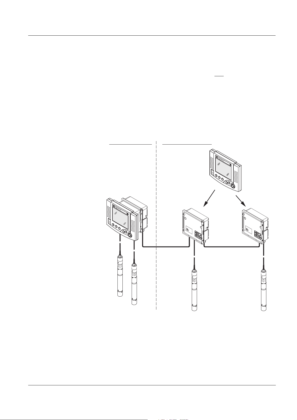
Connecting
MIQ modules
There are two basic mounting variants for connecting the
MIQ modules:
Stack mounting - permanent mechanical and
electrical connection.
The housings of the MIQ modules are permanently mounted on one
another to form a stack. No cabling is necessary.
Distributed mounting - electrical connection via cable.
Locally separated MIQ modules or module stacks are connected
with one another via the SNCIQ or SNCIQ/UG cable.
The following diagram shows an IQ S
ENSOR NET system with two
mounting variants (Fig. 1-3).
ba76019e01 12/2012
Fig. 1-3 Example of an IQ SENSOR NET system configuration
IQ sensors Up to 20 IQ sensors of any type can be used in the system
2020 XT USB. They can be connected to any MIQ module that has a
free connection for the IQ S
ENSOR NET. The connection between the
IQ sensor and MIQ module is made via the SACIQ sensor connection
cable. The IQ sensor connection cable is connected with the plug head
connector of the IQ sensor via a screwable socket to form a watertight
connection. As a result, the IQ sensor can be quickly removed for
maintenance activities and then connected again.
1 - 9
Page 16
Overview System 2020 XT USB
7
1
2
3
4
5
6
Power
!
O
K
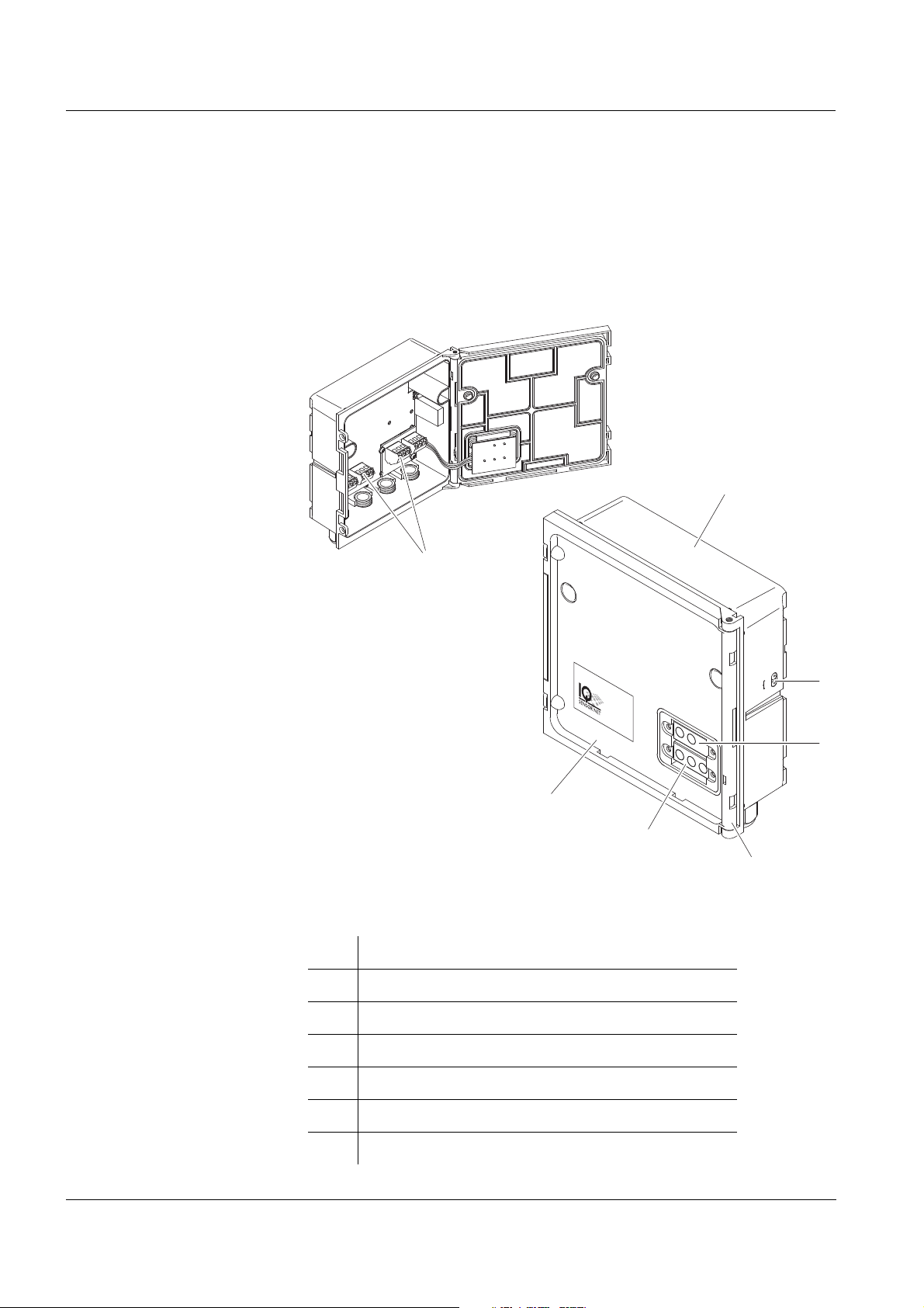
1.2.5 MIQ modules
Some of the IQ S
ENSOR NET components are so-called MIQ modules
with different functions.
All MIQ modules have a standard housing with the following features
(Fig. 1-4):
1 - 10
Fig. 1-4 MIQ module
1 Housing
2 Lid
3 Hinge
4 Contacts for voltage and communication
5 Contacts for the local identity function
6 Voltage LEDs
7 Terminal strip (example)
ba76019e01 12/2012
Page 17

System 2020 XT USB Overview
Common characteristics
of the MIQ modules
Module lid with hinge
Due to its wide opening angle, the lid provides a large space for
working inside the module (e.g. for connecting lines to the terminal
strip).
Docking facility
MIQ modules can be mechanically docked onto one another. As a
result, several MIQ modules can be mounted in the form of a stack
to create a single unit (stack mounting). At the same time, docking
enables the MIQ modules to be electrically connected with one
another via the module contacts on the front and back so that no
cabling is required. Even when it is part of a stack, each MIQ module
can be opened. In addition, a terminal component can be docked
onto each free lid front.
Terminal strip
Further IQ S
ENSOR NET components can be connected by cable to
the terminal strip inside the housing (distributed mounting). The
terminal strip enables IQ sensors to be connected via the SACIQ
sensor connection cable or the IQ S
ENSOR NET can be further
branched and extended here. Certain MIQ modules have a terminal
strip with further specific connections (e.g. power connection, relay
contacts, current outputs).
Local identity function
The local identity function is integrated in each MIQ module in the
form of a memory chip. This memory chip can store information such
as the designation of the measurement location and a specific
selection of IQ sensors for the measured value display. This
information is output when a terminal is docked and, thus, e.g.
enables the rapid finding of local IQ sensors for calibration.
Voltage diagnosis via LEDs
Two LEDs, yellow and red, on the side of the housing are used to
monitor the operational voltage of each MIQ module.
ba76019e01 12/2012
1 - 11
Page 18
Overview System 2020 XT USB
C
M
S
ESC
OK
1
3
4
5
76
2
Back
Front
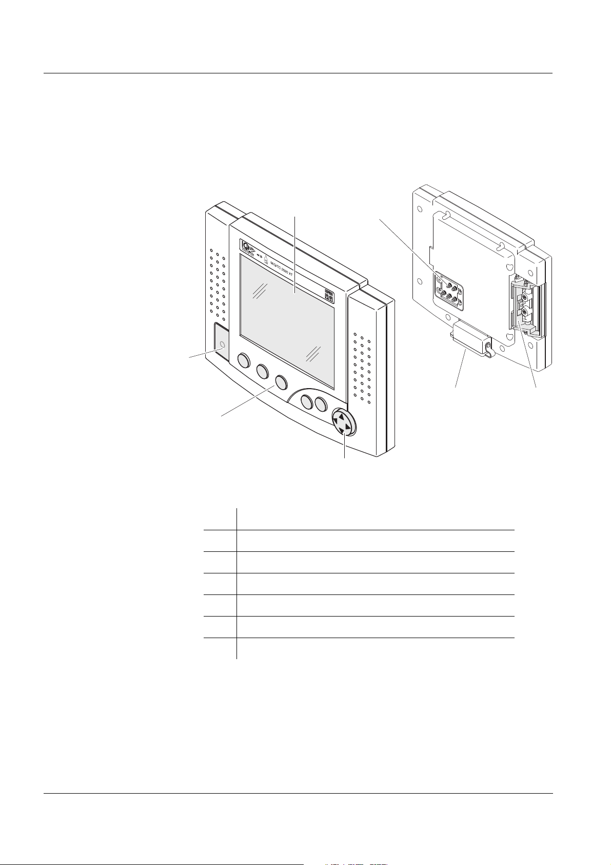
1.3 MIQ/TC 2020 XT terminal/controller
The MIQ/TC 2020 XT can be configured in the IQ SENSOR NET as a
controller (see section 1.3.1) or as a terminal (see section 1.3.2).
Fig. 1-5 MIQ/TC 2020 XT terminal/controller
1 Graphical display
2 Status LED
3 Keys
4 Arrow keys
5 Module contacts
6 USB-A interface with cover plate
7 Docking mechanism
1 - 12
ba76019e01 12/2012
Page 19
System 2020 XT USB Overview
M
C
S
OK
ESC
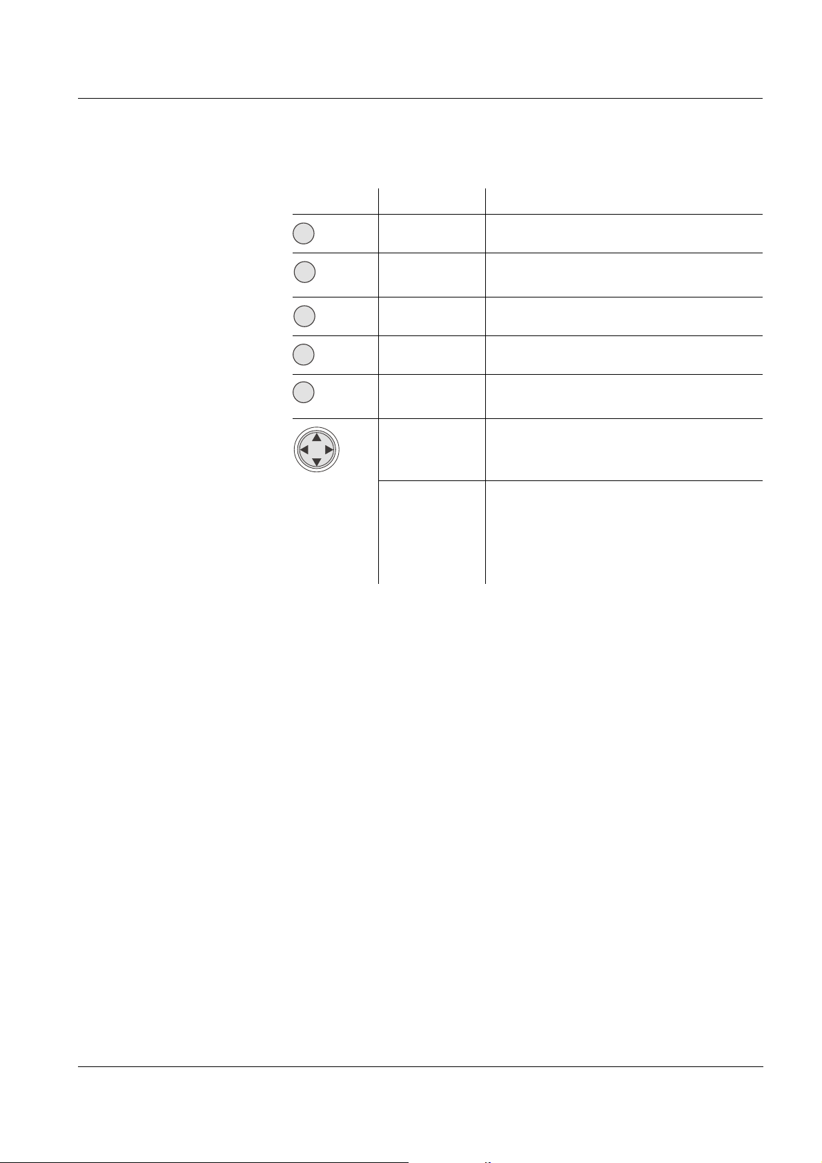
Keys The keys have the following functions:
Key Designation Functions
<M> – Switches the photometer on and off
<C> – Starts the calibration procedure for
the selected sensor
<S> – Opens the menu, System settings
<OK> – Opens the menu, Display/Options
<ESC> – Quits the current menu without
changing any settings
<▲> or
– Moves the selection in menus, lists
<▼>
and table columns by one position
upwards or downwards
(Arrow
keys)
<> or
– Moves the selection in tables by one
<>
position to the left or to the right
– Erases the character left of the
insertion point when entering
characters
1.3.1 Operation as terminal/controller
When configured as a controller, the MIQ/TC 2020 XT is a basic
component of the 2020 XT USB system and must therefore
permanently remain in the system.
The MIQ/TC 2020 XT is connected to the system by docking on the
free front cover of an MIQ module.
The controller function takes over the following tasks:
Control and monitoring of all IQ sensors
Control and monitoring of all current and relay outputs
Continuous diagnosis of the system, i.e. recording the information
and error messages of all modules and entering them in the system
log book (e.g.: voltage monitoring)
Recording measured data in the fixed interval
Communication with external digital interfaces such as
– USB memory device
– Modem
– PROFIBUS, Modbus, RS485
–PC
ba76019e01 12/2012
1 - 13
Page 20

Overview System 2020 XT USB
A terminal is required to display and set up the functions of the
controller. The following terminal components are suitable:
MIQ/TC 2020 XT configured as terminal/controller or as terminal
(compatible terminals, see section 1.4)
MIQ/T2020 PC
(with MIQ/IF232 interface module, PC, modem connection or
PROFIBUS environment).
The present component operating manual of the IQ S
ENSOR NET
System 2020 XT USB includes all functions of the MIQ/TC 2020 XT.
The connection to Profibus or Modbus is established with the
MIQ/(A-)PR and MIQ/(A-)MOD extension modules.
1.3.2 Operation as a terminal
The MIQ/TC 2020 XT configured as a terminal is an extension
component for the IQ S
ENSOR NET System. The MIQ/TC 2020 XT can
be used as a mobile control unit and docked on and removed from all
free front covers of MIQ modules. The docking is simply done by hand,
without using any tools.
The terminal function is the graphical user interface of the system. It
is used for the following purposes:
Display of measured values
Setting of IQ sensors, outputs, terminal characteristics, date, time,
etc.
Execution of maintenance and calibration work
Display of calibration data
1 - 14
Display of components lists (IQ sensors and outputs)
Display of the log book entries
If the MIQ/TC 2020 XT is registered in the system as a terminal, it is
mobile and can be removed at any time. If the main controller of the
system fails, the MIQ/TC 2020 XT automatically assumes the job of the
failed controller (see section 1.3.3).
ba76019e01 12/2012
Page 21

System 2020 XT USB Overview
1.3.3 Operation as backup controller
Automatic backup
function
If the MIQ/TC 2020 XT is configured as a terminal, it has a backup
controller that assumes the basic functions of the IQ S
ENSOR NET
controller in the case of its failure. Thus the operating safety of the
system is considerably increased. For these purposes the MIQ/
TC 2020 XT regularly and automatically saves the system
configuration during the normal terminal operation.
System configuration The system configuration incudes the following allocations and
settings:
Settings of sensors and diff. sensors
Settings of outputs and links
Edit list of sensors
Edit list of outputs
Measured value recording (datalogger settings)
List of all components including software versions but without
terminal information.
Application-related sensor calibration (e.g. matrix adjustment)
In the IQ S
ENSOR NET, the system configuration is stored in the
controller (MIQ/TC 2020 XT).
Functions of the MIQ/
TC 2020 XT
when operating as a
If the MIQ/TC 2020 XT operates as a backup controller, all basic
IQ S
ENSOR NET functions are carried out. Relay interfaces and current
interfaces, PROFIBUS, Modbus and RS485 work without restrictions.
backup controller
Restrictions of the MIQ/
TC 2020 XT
The following functions are not supported
:
Continuation of the data logger operation of the main controller
when operating as a
backup controller
Continuation of the modem communication of the main controller if
the modem is connected to the interface of the MIQ/TC 2020 XT
(configured as controller).
A redundant data logging function can be set up with the aid of the
MIQ/IF232 interface module.
Manual backup function In addition to the automatic backup of the system configuration you can
manually store the system configuration on a USB memory device at
any time. In the case of a system failure you can then transfer the
stored configuration from the USB memory device to another controller.
ba76019e01 12/2012
1 - 15
Page 22

Overview System 2020 XT USB
1.3.4 USB interface
The USB interface of the MIQ/TC 2020 XT provides the following
functions:
Connection of a USB memory device for data transmission (see
section 4.9)
– Measurement data
– Calibration data
– Configuration data
– Log book
Connection of a PC for data transmission or for control via the MIQ/
T2020 PC software terminal (see operating manual ba64108
"IQ S
ENSOR NET Softwarepack"). The various connection options
(direct connection, modem, network etc.) are described in the
operating manual ba75790 "Remote connection to the
IQ S
ENSOR NET 2020 XT USB".
Operation of the
MIQ/TC 2020 XT
in the open
Connection of an electronic key for simple system access with
enabled access control (see section 5.4.2)
Connection of a USB hub to multiply the USB interface
Note
The USB interface is equipped with a protective cover.
Only remove the protective cover if you want to connect a USB device.
Close the connection immeditaley after disconnecting the USB device.
If the USB connection remains open there is the risk of corrosion.
Do not leave any USB devices permanently connected to the USB
interface. There is the risk of corrosion.
1 - 16
ba76019e01 12/2012
Page 23

System 2020 XT USB Overview
1.3.5 Status LED
The status LED informs you of the state of the system:
Status LED Meaning
Permanently on–The IQS
Permanently
– No power supply
off
Flashes – The IQ S
–The IQS
– A communication error in the IQ S
– An invalid measure value
– The backup controller has assumed controller
function
The LED flashes as long as the error is present
(even if the log book message of the error has
already been acknowledged). More detailed
information on the error is given in the log book.
ENSOR NET is running fault-free
ENSOR NET discovered an alarm.
ENSOR NET discovered an error, e.g.:
ENSOR NET
ba76019e01 12/2012
1 - 17
Page 24

Overview System 2020 XT USB
1.4 Behavior of the IQ SENSOR NET in case of error
1.4.1 Behavior of the IQ SENSOR NET in case of power failure
The system configuration (Settings of sensors and diff. sensors and
Settings of outputs and links) is stored permanently
All stored measured data remain permanently available
Linked current outputs and relay outputs switch to the non-active
condition.
Current output: 0 mA current
Relay output: Relays open
For details, refer to the component operating manual of the current
or relay output module.
When the power supply is available again, the system is
automatically restarted, starts working again and switches to the
measured value display
During the restart, an entry informing of the power failure is made in
the log book.
1.4.2 Behavior of the IQ S
ENSOR NET if a components fails
If the operating voltage is too low, the LEDs on the MIQ modules
extinguish.
The blue status LED of the MIQ/TC 2020 XT flashes
If active components (e.g. sensors or output modules) cannot be
contacted, an entry is made in the log book. The error symbol
flashes on the display.
The Edit list of sensors or Edit list of outputs display shows a
question mark "?" for the component.
Component Behavior
IQ sensor The configuration for the IQ sensor (Settings of
sensors and diff. sensors) remains stored.
Current measured values are not available.
The measured value display shows ERROR.
MIQ modules If an active module fails, an entry is made in the
log book. The error symbol flashes on the
display.
1 - 18
The configuration for these modules is retained
(e.g. links with output modules).
ba76019e01 12/2012
Page 25

System 2020 XT USB Overview
Component Behavior
Controller No current measured data can be displayed,
processed or stored.
If communication with the controller is disturbed,
output modules activate the error behavior after
2 minutes (see component operating manual of
the output module).
Terminal The measured value display is not updated.
The display does not react to entries.
The system continues working.
Stored measured data and the system
configuration remain stored in the MIQ/
TC 2020 XT.
Power supply
like power failure (see section 1.4.1)
module
1.4.3 Availability of the system
As a basic principle, the IQ S
ENSOR NET offers a very high availability.
This is achieved by
The two-wire connection technique that is not interference-prone
The digital signal transmission resulting from this
Tools for error diagnosis
– LEDs on the MIQ modules to check the available voltage
– Log book messages with instructions to eliminate problems
The possibility to simply assign substitute components for
components to be exchanged.
Replacing components is simple and can be performed very quickly
(see section 7.4). The system configuration (Settings of sensors and
diff. sensors and Settings of outputs and links) and the measured
data are stored in the controller and remain stored when other
components are used.
ba76019e01 12/2012
1 - 19
Page 26

Overview System 2020 XT USB
Preventive actions to
optimize the availability
of the system
If the requirements of the availability are especially high, you can
further improve the availability of the system as follows:
Install identical components in the system.
If the requirements of the availability are high, components can be
installed doubly in the system (exception: controller component).
Back up the controller function with the aid of a second MIQ/
TC 2020 XT configured as a terminal.
The MIQ/TC 2020 XT has a redundant controller function. It
maintains all essential functions of the system in the case of a
controller malfunction and saves all settings. The controller
operation starts automatically.
Keep substitute components ready.
The system automatically recognizes substitute components of
active components (IQ sensors and the output modules). They are
easily integrated in the system by assigning them as substitute
components.
Save the system configuration.
The system configuration (Settings of sensors and diff. sensors and
Settings of outputs and links) can be saved on a PC. Transmission
takes place via the USB interface (alternative options: see section
1.2.3). The stored system configuration can be loaded from the PC
on a substitute controller if necessary.
1 - 20
ba76019e01 12/2012
Page 27
System 2020 XT USB Safety instructions
2 Safety instructions
This operating manual contains essential instructions that must be
followed during the commissioning, operation and maintenance of the
ENSOR NET system. Thus, it is essential for the operator to read this
IQ S
component operating manual before carrying out any work with the
system.
Some components such as IQ sensors and special MIQ modules are
delivered with their own component operating manual. It is also
important to read the S
and all component operating manuals in the vicinity of the
ENSOR NET system if possible.
IQ S
AFETY chapter in this manual. Keep the system
General safety
instructions
Other labels
Safety instructions in this operating manual are indicated by the
warning symbol (triangle) in the left column. The signal word (e.g.
"Caution") indicates the danger level:
Warning
indicates instructions that must be followed precisely in order to
prevent serious dangers to personnel.
Caution
indicates instructions that must be followed precisely in order to
avoid slight injuries to personnel or damage to the instrument or
the environment.
Note
indicates notes that draw your attention to special features.
Note
indicates cross-references to other documents, e.g. component
operating manuals.
Target group The IQ SENSOR NET system was developed for online analysis. Some
ba76019e01 12/2012
2.1 User qualification
maintenance activities, e.g. changing the membrane caps in D.O.
sensors, require the safe handling of chemicals. Thus, we assume that
the maintenance personnel is familiar with the necessary precautions
to take when dealing with chemicals as a result of their professional
training and experience.
2 - 1
Page 28

Safety instructions System 2020 XT USB
Special user
qualifications
The following installation activities may only be performed by a
qualified electrician:
Connection of the MIQ/PS power supply module to the power line
(see MIQ/PS module manual).
Connection of external, line voltage-carrying circuits to relay
contacts (see module manual of the relay output module).
2.2 Authorized use
The authorized use of the IQ SENSOR NET system consists only of its
use in online analysis.
Please observe the technical specifications according to chapter 8
T
ECHNICAL DATA. Only operation and running according to the
instructions in this component operating manual is authorized.
Any other use is considered to be unauthorized. Unauthorized use
invalidates any claims with regard to the guarantee.
2.3 General safety instructions
All components of the System IQ SENSOR NET are constructed and
inspected in accordance with the relevant guidelines and norms for
electronic instruments (see chapter 8 T
They left the factory in a safe and secure technical condition.
ECHNICAL DATA).
Function and
operational safety
The failure-free function and operational safety of the IQ S
ENSOR NET
components are only guaranteed if the generally applicable safety
measures and the special safety instructions in this operating manual
are followed during their use.
The failure-free function and operational safety of the IQ S
ENSOR NET
components are only guaranteed under the environmental conditions
that are specified in chapter 8 T
If IQ S
ENSOR NET components are transported from a cold environment
ECHNICAL DATA.
into a warm environment, this can cause a functional malfunction
through the formation of condensation. In this case, wait for the
components to adjust to room temperature before recommissioning.
2 - 2
ba76019e01 12/2012
Page 29

System 2020 XT USB Safety instructions
Safe operation If safe operation is no longer possible, the IQ SENSOR NET must be
taken out of operation and secured against inadvertent operation.
Safe operation is no longer possible if components:
have been damaged in transport
have been stored under adverse conditions for a lengthy period of
time
are visibly damaged
no longer operate as described in this manual.
Obligations of the
operator
If you are in any doubt, contact the supplier of your IQ S
The operator of the IQ S
ENSOR NET system must ensure that the
ENSOR NET.
regulations and guidelines listed below are followed when dealing with
dangerous substances:
EEC guidelines relating to safety at work
National laws relating to safety at work
Safety regulations
Safety datasheets of the chemicals manufacturers.
Warning
A circuit (except for the line power supply), that is connected to an
ENSOR NET component, must not feed any voltages or
IQ S
currents that are not allowed. It has to be made sure that the
circuit at any time meets all requirements of a Limited circuit or
Limited Power as well as of SELV (Safety Extra Low Voltage).
These include the following limiting value specifications:
AC voltage: max. 30 V effective / 42.4 V peak
DC voltage: max. 60 V
Current limit: max. 8 A
Power output limitation: max. 150 VA
ba76019e01 12/2012
2 - 3
Page 30

Safety instructions System 2020 XT USB
2 - 4
ba76019e01 12/2012
Page 31

System 2020 XT USB Installation
3 Installation
3.1 Scopes of delivery
3.1.1 MIQ modules
The following parts are contained in the scope of delivery of an
MIQ module:
MIQ module
Accessory kit with:
– Contact carrier with screws
– ISO cap nuts with screws and ring washers
– Cable glands with sealing gaskets
Operating manual.
3.1.2 Terminal/Controller
The following parts are contained in the scope of delivery of the MIQ/
TC 2020 XT terminal/controller:
MIQ/TC 2020 XT
Screw to fix the terminal on the MIQ module
Operating manual.
3.2 Requirements of the measurement location
The respective measurement location of all IQ SENSOR NET
components must meet the environmental conditions specified in
section 8.1 G
ENERAL SYSTEM DATA.
ba76019e01 12/2012
3 - 1
Page 32

Installation System 2020 XT USB
- Sum of all line lengths max. 1000 m
- Of these, max. 500 m branch lines
altogether
- Single branch line max. 250 m
Total line lengths of > 1000 m
can be realized with the
signal amplifier module
MIQ/JBR
Total line lengths < 400 m
not have to be taken into account
do
More power required due to cable losses:
From 1 watt per
100 m additional line length.
400 m total line length
- Position power supply modules near
main consumers (e. g. UV/VIS sensor)
- Further power supply module or adjustment of infrastructure if necessary.
Power requirement = SP of all consumers
- Number and types of required sensors
- Measuring locations to be designed
- Number of required operating locations
- Distances
- Infrastructure, process environment etc.
Rough planning
Rough determination of power requirement
Consideration of cable losses
Rating
Fine adjustment
IQ topology + layoutS
ENSORNET
Power requirement of components
Total power requirement
Number of power supply modules
required
Fundamentals of planning
Start
End
SP of all power supply modules >
total power requirement
Arrangement of
power supply modules
3.3 System planning
Overview of the
planning steps
3 - 2
Fig. 3-1 System planning
ba76019e01 12/2012
Page 33

System 2020 XT USB Installation
3.4 Basic requirements for optimum installation
3.4.1 General information
The IQ S
ENSOR NET supplies all components with low voltage as well
as digital communication via a shielded 2-wire line.
Due to this characteristic, the following factors must be taken into
account in the planning of an IQ S
ENSOR NET system:
Power consumption of all components (power rating). Primarily, this
determines the number of power supply modules required (section
3.4.2).
Distance of the components from one another. Large distances may
require a further MIQ/PS power supply module and/or an MIQ/JBR
signal amplifier module (section 3.4.3).
Placement of the MIQ/PS power supply modules in the
IQ S
ENSOR NET (effect on the power supply - section 3.4.3).
Caution
Only IQ SENSOR NET products may be used in the IQ SENSOR NET.
3.4.2 Drawing up the power rating
Power rating - why? All components in the system require a specific level of electrical power
for operation. Thus, it is necessary to draw up a power rating after
selecting all the components. At the same time, this can determine
whether the entire power requirement of all components (consumers)
is covered by the existing MIQ power supply modules. If this is not the
case, the power available in the system must be increased by further
MIQ power supply modules.
ba76019e01 12/2012
Note
The power rating provides an initial guide value. In specific limiting
cases, the power supply may be insufficient despite the positive power
rating. Long cable lines, for example, result in additional power losses
that may have to be compensated by further MIQ power supply
modules. This can be checked for the planned installation by following
section 3.4.3.
The total power requirement P of all consumers can be determined
from the following table:
3 - 3
Page 34

Installation System 2020 XT USB
Power requirement of
ENSOR NET
IQ S
components
Component Power requirement [W]
IQ sensors
®
SensoLyt
TriOxmatic
TriOxmatic
TriOxmatic
FDO
TetraCon
VisoTurb
ViSolid
AmmoLyt
NitraLyt
VARiON
NitraVis
CarboVis
NiCaVis
700 IQ (SW) 0.2
®
700 IQ (SW) 0.2
®
701 IQ 0.2
®
702 IQ 0.2
®
70x IQ (SW) 0.7
®
700 IQ (SW) 0.2
®
700 IQ 1.5
®
700 IQ 1.5
® Plus
700 IQ 0.2
® Plus
700 IQ 0.2
® Plus
700 IQ 0.2
®
70x IQ (TS) 8.0
®
70x IQ (TS) 8.0
®
70x IQ 8.0
MIQ modules
MIQ/JB 0
MIQ/JBR 0
MIQ/CR3 3.0
MIQ/C6 3.0
MIQ/R6 1.5
MIQ/IC2 0.2
+ 2.2 W per connected
WG 20 A2 power supply/isolator
MIQ/CHV 2.0
MIQ/CHV PLUS 1.0
MIQ/Blue PS 0.6
MIQ/A 1.5
MIQ/(A)-PR 3.0
MIQ/(A)-MOD 3.0
Terminal, Controller
MIQ/TC 2020 XT 3.0
MIQ/IF232 (+ MIQ/T2020 PC) 0.2
3 - 4
ba76019e01 12/2012
Page 35

System 2020 XT USB Installation
Determining the number
of MIQ power supply
From the value determined for the power requirement, determine the
number of the MIQ power supply modules as follows:
modules
Total power requirement P Number of MIQ power supply
P
18 W
36 W
54 W
72 W
90 W
Sample configuration Power
requirement [W]
(component)
modules
≤ 18 W 1
< P ≤ 36 W 2
< P ≤ 54 W 3
< P ≤ 72 W 4
< P ≤ 90 W 5
< P ≤ 108 W 6
Total power
requirement P [W] (sum
of the components)
Number of
power supply
modules
required
1 MIQ/TC 2020 XT
3.0 3.0 1
(terminal/controller)
+ 1 MIQ/TC 2020 XT
+ 3.0 6.0 1
(terminal)
®
+ 1 NiCaVis
+ 1 VisoTurb
+ 1 SensoLyt
705 IQ + 8.0 14,0 1
®
700 IQ + 1.5 15,5 1
®
700 IQ + 0.2 15,7 1
+ 1 MIQ/CR3 + 3.0 18.7 2
+ 1 MIQ/CR3 + 3.0 21.7 2
+ 1 MIQ/TC 2020 XT
+ 3.0 24,7 2
(terminal)
Note
The determined number of power supply modules required in the
IQ S
ENSOR NET can increase if the cables are very long (see section
3.4.3).
Power supply with the
aid of the MIQ/Blue PS
radio module
ba76019e01 12/2012
The MIQ/Blue PS radio module can provide power for components with
a total of up to 7 W power consumption on an IQ S
ENSOR NET island.
The relevant details are given in the operating manual of the MIQ/
Blue PS.
3 - 5
Page 36

Installation System 2020 XT USB
A cable section is the longest continuous length of cable from an
MIQ power supply module to a consumer. Sensor connection
cables up to 15 m are not taken into account in this.
3.4.3 Effect of the cable length
Voltage drop due to
cable lengths
Guideline If the power supply modules are positioned in the vicinity of the main
The length of the cables in the IQ S
ENSOR NET affects
the operating voltage available for a component
the quality of data transmission.
Note
All information applies to SNCIQ cable material only. As regards the
copper wire diameter and dielectric, this cable is especially designed
for the combined energy and data transmission via great distances and
ensures the lightning protection characteristics stated in chapter 8
T
ECHNICAL DATA.
Very long cables in the IQ S
ENSOR NET cause voltage drops with
growing distance from the power supply module. If the voltage is under
the limit values, further IQ power supply modules must be used to
compensate.
consumers and the total cable length is no more than 400 m, no
additional cable losses have normally to be taken into account. Main
consumers are components with a power consumption of 5 W or more.
Note
When determining the number of power supply modules required, the
most unfavorable design has to be taken into account for mobile
components (Terminals). I. e., take into account
Determining the length
of the cable section
the maximum number of mobile components and
their greatest possible installation distance from the power supply
module.
A diagram is used to determine whether an additional MIQ power
supply module is necessary for the planned installation. To do so, the
length of the cable section must be determined.
3 - 6
ba76019e01 12/2012
Page 37

System 2020 XT USB Installation
L1
= 150 m
L4 = 200 m
L2 = 200 m L3 = 300 m
MIQ/PS
MIQ/24V
C
M
S
ESC
OK
MIQ/TC 2020 XT
<<
LAB
Example The following figure shows the length of the cable section L made up of
the partial lengths L1, L2 and L3 as the cable section L4 is shorter than
L3:
L = L1 + L2 + L3
Fig. 3-2 Example of determining the cable section
ba76019e01 12/2012
3 - 7
Page 38

Installation System 2020 XT USB
Checking the power
supply
1 Determine the length of the cable section for the planned
installation.
2 Determine the sum of the power consumption of all consumers
along the cable section (including IQ sensors).
3 Enter both determined values as a point in the following
diagram.
Note
To make it easier it is assumed that all consumers are located at the
end of the cable section.
3 - 8
Fig. 3-3 Diagram to check the power supply
4 Evaluation:
If the point is in the lower, valid range, no additional power
supply module is required.
If the point is in the upper, invalid range, an additional power
supply module is required. Install this power supply module in
the vicinity of the main consumers of this section, or, if not
possible, - starting from the primary MIQ power supply module
- approx. at that point of the section where the maximum cable
length is exceeded (see following example).
ba76019e01 12/2012
Page 39

System 2020 XT USB Installation
Example Problem:
Consumers with a total power requirement of 9 W are positioned on a
cable section of 650 m. Is the power supply with one power supply
module sufficient? At which point must a further power supply module
be installed if necessary?
Proceeding:
Enter both values as a point in the diagram (point "x" in Fig. 3-3).
Result: the point is in the invalid range. I. e. the power supply is not
sufficient.
Draw down a vertical line from the point until the line crosses the limit
between the upper and lower range. The intersecting point specifies
the maximum cable length for the existing power requirement (at
approx. 470 m). This is the place where the additional power supply
module is required.
If any main consumers are near the place, the power supply module
should be installed in their vicinity (ideally, directly on them).
Quality of data
transmission
Note
After commissioning, you can check the voltage directly on the
MIQ modules or on the terminal connections of the IQ sensors (see
section 7.2.2). The limits of the voltage levels are given in section
7.2.2 M
EASURING THE VOLTAGE of this operating manual.
If the sum of all line lengths (including the SACIQ sensor connection
cable) exceeds 1000 m, an MIQ/JBR signal amplifier module must be
installed in the system. More details of this are given in the MIQ/JBR
component operating manual.
ba76019e01 12/2012
3 - 9
Page 40

Installation System 2020 XT USB
3.4.4 Optimum installation of MIQ power supply modules
Basic rules Install the MIQ power supply modules as near as possible to the
ENSOR NET components with the highest power consumption.
IQ S
This also applies in the case of several MIQ power supply modules
in the system.
If possible, assemble the IQ S
ENSOR NET in a star configuration from
the MIQ power supply modules.
3.4.5 Installation guidelines for lightning protection
When using the IQ S
ENSOR NET measuring technique, particularly in
outdoor areas, adequate protection against (electrical) surges must be
provided. A surge is a summation phenomenon of surge voltage and
surge current. It is generated through the indirect effect of a lightning
event or switching operation in the mains, in the grounding system and
in information technology lines.
To be adequately protected against the damaging effects of surges, an
integrated concept of the following protective measures is required:
technical protective measures inside the instrument, and
exterior protective measures of the installation environment.
With YSI online measuring technique, the technical protective
measures inside the instrument are already integrated as the so-called
lightning protection (see chapter 8 T
ECHNICAL DATA).
The exterior protective measures of the installation environment can be
carried out observing the following guidelines:
1 All lines of IQ S
ENSOR NET systems must be
a) installed inside (or else close to) the grounded metallic mounting
constructions, e.g. handrails, pipes and posts if possible
b) or, particularly in the case of longer lines, laid in the ground.
Background: the small distance from the grounded metal
construction or the installation in the ground prevents the
development of induction loops between the cable and the ground
hazardous in the case of lightning strikes.
3 - 10
ba76019e01 12/2012
Page 41

System 2020 XT USB Installation
2 The SNCIQ or SNCIQ-UG cable material must be used exclusively.
This cable material, particularly the high line cross section of the
cable shielding (1.5 mm²), is an important prerequisite for the
hazard-free discharging of the surge without inadmissibly high
overvoltages developing along the line at the same time that could
have a damaging effect on the individual IQ S
ENSOR NET
components. We strongly recommend not to use any other cables,
which normally have a considerably lower shielding wire crosssection.
3 All metallic mounting constructions, handrails, pipes, posts etc. on
which MIQ modules are installed must be connected to the local
potential equalization system and the grounding system or must be
individually sufficiently grounded locally according to the codes of
practice.
For the individual grounding of the measuring point the mounting
construction must be solidly connected by means of a large-area
auxiliary electrode with the measuring medium.
Metallic control shafts/pipes and other large-area metallic bodies
that reach into the measuring medium are, for example, ideal for use
in the grounding of the mounting construction.
This creates a set path for the main surge. As a result it is possible
to avoid the surge being discharged via the IQ IQ S
ENSOR NET cable
and via the valuable sensors in the measuring medium.
4 The contacts of the MIQ modules always have to be protected with
the respective contact covers when they are not used by terminal
components. The contact covers improve the insulation against
electric fields of a thunderstorm by enlarging air gaps and creepage
distances.
5 We recommend to install a metal or nonmetal sun shield at each
open air location of MIQ modules. Sun shields protect the electric
field lines in the area of the MIQ module through an advantageous
development of the electrical field lines in the area of the MIQ
module and promote the dissipation of the surge via the mounting
construction.
6 The line voltage that supports the measuring system must
correspond to overvoltage category II. Normally this is ensured by
the public operators of the supply network systems. In companyowned networks, e.g. in all power supply systems owned by
wastewater treatment plants, this must be kept separate by a
potential equalization and asurge protection system for the plant.
ba76019e01 12/2012
3 - 11
Page 42

Installation System 2020 XT USB
7 The IQ SENSOR NET safety and lightning protection concept is partly
based on the high-quality protective insulation of the line power
supply units and the total system. It does not have or require any
protective ground (PG) conductor or earth terminal. Avoid any direct
connection of the IQ S
ENSOR NET connections or the metallic sensor
enclosures with the local grounding or potential equalization system
and with metallic construction elements (see point 9).
8 Additional external lightning protection measures directly on the
ENSOR NET system or its components, e.g. the use of
IQ S
overvoltage surge arresters, are not necessary for protection
against the indirect effects of lightning and could possibly result in
malfunctions.
9 For the realisation of the internal lightning protection of the system
(e.g. wastewater treatment plant control stands) and for the
protection of IQ S
into buildings or distributions coming from the IQ S
ENSOR NET external resources, cable entry points
ENSOR NET must
be carried out as follows:
– The shield of SNCIQ or SNCIQ-UG cables can be connected to
the local potential equalization with a gas overvoltage surge
arrester. Use shielding terminals for the contacting of the shield
(e.g. those of the PROFIBUS-System). The shield of the cable
must not be opened under any circumstances.
– 0/4-20 mA interfaces must be realized with shielded cables. The
cable shield must be connected directly to the potential
equalization(s) provided. If plant potential equalization systems
are provided on both sides, the shield must also be connected on
both sides. The inner conductors must have no contact with the
potential equalization.
– PROFIBUS cables and Modbus cables have to be installed
according to the prescriptions of the respective bus system.
– Relay lines should be connected to the local potential
equalization in order to provide general and consistent protection
via gas overvoltage surge arresters.
3 - 12
ba76019e01 12/2012
Page 43

System 2020 XT USB Installation
3.5 Connecting system components
3.5.1 General information
The IQ S
ENSOR NET system components are connected to form a
functioning unit in the following ways:
Stacked mounting of MIQ modules
Up to three MIQ modules can be installed and mechanically
connected with one another to form a stack at a single location. The
contacts on the front and rear automatically create the electrical
connection between the MIQ modules in the stack (section 3.5.2).
Distributed mounting of MIQ modules
Individual MIQ modules or an assembled module stack are installed
at various locations (for example, a central control unit and an
MIQ branching module for connecting IQ sensors at the edge of the
basin). The spatial distance is bridged with the aid of the SNCIQ or
SNCIQ/UG cable (section 3.5.3).
Connection of IQ sensors:
IQ sensors are connected to an MIQ module with the aid of the
SACIQ cable. This cable is available in different lengths. The
MIQ module must have a free SENSORNET connection on the
terminal strip. On the sensor side, the connection is made via a plug
that is standard for all IQ sensors (section 3.5.4).
Docking of a terminal unit:
A terminal unit is attached to the lid of a free MIQ module with the
aid of a quick-release locking mechanism (section 3.5.5).
Caution
Distributed mounting is only allowed in a star configuration. The
system must nowhere be closed to form a ring. Only use the
assembly material provided for the installation.
ba76019e01 12/2012
3 - 13
Page 44

Installation System 2020 XT USB
3.5.2 Stacked mounting of MIQ modules:
Caution
For optimum stability, a maximum of three MIQ modules can be
mounted in any one stack. Only one MIQ power supply module
may be mounted per module stack.
Mounting direction MIQ modules can be stacked on top of one another from both sides. All
the required installation materials are contained in the scope of delivery
of the MIQ modules.
Variant 1 - stack expansion
forwards.
The back of an MIQ module is
attached to the lid of another
MIQ module
(page 3-15).
Variant 2: - stack expansion
backwards.
The lid of an MIQ module is
attached to the back of another
MIQ module (page 3-18).
Which variant is suitable for a specific case depends on whether and
how an MIQ module is already permanently installed at a location (e.g.
on a wall or in a panel), among other factors.
Note
In the case of panel mounting, the front MIQ module can only be
installed individually in the switch cabinet aperture. Only then can
further MIQ modules be added to its back (variant 2). If necessary,
dismantle the front MIQ module from an already mounted stack before
mounting.
Materials required 2 x ISO blind nuts M4
2 x cheese-head screws M4x16 with plastic washer
3 - 14
1 x contact base with two plastic tapping screws.
Tools Phillips screw driver.
ba76019e01 12/2012
Page 45

System 2020 XT USB Installation
For stack mounting remove label
and install contact carrier
13
24
Back Front
MIQ module MIQ module
7
5
6
Both installation variants are described below. To dismantle a module
stack, proceed in the reverse order to mounting the stack.
Preparing the stack
mounting
Variant 1:
Fig. 3-4 Preparing MIQ modules for stack mounting (variant 1)
Stack expansion forwards
1 Remove the covers from the drilled mounting holes (pos. 1 and
3 in Fig. 3-4).
Mounting the contact
base
ba76019e01 12/2012
2 Remove the contact cover (pos. 2).
3 Pull off the adhesive label (pos. 4).
Fig. 3-5 Mounting the contact base (variant 1)
3 - 15
Page 46

Installation System 2020 XT USB
9
8
Caution
Only use the plastic tapping screws supplied for attaching the
contact base. They ensure the correct fit.
4 Attach the contact base (pos. 5 in Fig. 3-5) on the front
MIQ module with the two plastic tapping screws (pos. 6).
5 On the front MIQ module, remove the two countersunk screws
(pos. 7 in Fig. 3-5) and swing open the module lid.
Premounting the ISO
blind nuts
Fig. 3-6 Premounting the ISO blind nuts (variant 1)
6 Insert the cheese-head screws (pos. 8 in Fig. 3-6) with the
plastic washers in the drilled mounting holes in the enclosure
and loosely screw in the ISO blind nuts (pos. 9).
3 - 16
ba76019e01 12/2012
Page 47

System 2020 XT USB Installation
7
Stacking the
MIQ modules
Fig. 3-7 Stacking the MIQ modules (variant 1)
Fig. 3-8 Closing the enclosure (variant 1)
7 Attach the prepared MIQ module to the lid of the back
MIQ module. At the same time, ensure that the two clips on the
front MIQ module click into place in the lid of the back
MIQ module. Subsequently, tighten the two screws (pos. 8 in
Fig. 3-6).
8 Check the position of the SN terminator switch and correct it if
necessary (see section 3.9.1).
9 Close the lid of the front MIQ module and fix it with the two
countersunk screws (pos. 7 in Fig. 3-8).
ba76019e01 12/2012
3 - 17
Page 48

Installation System 2020 XT USB
5
For stack mounting remove label
and install contact carrier
13
24
Back Front
MIQ module MIQ module
6
7
Variant 2: stack expansion backwards
Preparing the stack
mounting
Fig. 3-9 Preparing the MIQ modules for stack mounting (variant 2)
Mounting the contact
base
1 Remove the covers from the drilled mounting holes (pos. 1 and
3 in Fig. 3-9).
2 Remove the contact cover (pos. 2).
3 Pull off the adhesive label (pos. 4).
4 On the back MIQ module, remove the two countersunk screws
(pos. 5) and swing open the module lid.
Fig. 3-10 Mounting the contact base (variant 2)
3 - 18
ba76019e01 12/2012
Page 49

System 2020 XT USB Installation
8
9
Caution
Only use the plastic tapping screws supplied for attaching the
contact base. They ensure the correct fit.
5 Attach the contact base (pos. 6 in Fig. 3-10) on the front
MIQ module with the two plastic tapping screws (pos. 7).
Premounting the ISO
blind nuts
Fig. 3-11 Premounting the ISO blind nuts (variant 2)
6 Insert the cheese-head screws (pos. 8 in Fig. 3-11) with the
plastic washers in the drilled mounting holes in the module lid
and loosely screw in the ISO blind nuts (pos. 9).
ba76019e01 12/2012
3 - 19
Page 50

Installation System 2020 XT USB
5
Stacking the
MIQ modules
Fig. 3-12 Stacking the MIQ modules (variant 2)
Fig. 3-13 Closing the enclosure (variant 2)
7 Attach the prepared MIQ module to the back of the front
MIQ module. At the same time, ensure that the two clips on the
front MIQ module click into place in the lid of the back
MIQ module. Subsequently, tighten the two screws (pos. 8 in
Fig. 3-11).
3 - 20
8 Check the position of the SN terminator switch and correct it if
necessary (see section 3.9.1).
ba76019e01 12/2012
Page 51

System 2020 XT USB Installation
9 Close the back MIQ module and fix it with the two countersunk
screws (pos. 5 in Fig. 3-13).
3.5.3 Distributed mounting of MIQ modules
General information The following IQ S
mounting:
SNCIQ cable
SNCIQ/UG earth cable - suitable for underground laying according
to VDE 01816, Part 2 and DIN/VDE 0891, Part 6.
The cables are delivered as piece goods (please specify length when
ordering!).
Each MIQ module has a row of terminal strips in the housing. The two
3-fold terminal strips on the right are always reserved for the
connection of further IQ S
"SENSORNET 1" and "SENSORNET 2").
Some MIQ modules have additional "SENSORNET" connections
("SENSORNET 3" and "SENSORNET 4") on the left of the terminal
strip.
Caution
The IQ SENSOR NET cable may only be connected to the
SENSORNET connections. No wire of the cable may be connected
with an external electrical potential. Otherwise, malfunctions
could occur.
ENSOR NET cables can be used for distributed
ENSOR NET components (designation
Materials required 1 x SNCIQ or SNCIQ/UG connection cable (see chapter 10
ba76019e01 12/2012
Note
IQ S
ENSOR NET cables must always be installed separately at a
minimum distance of 20 cm from other lines that carry a voltage greater
than 60 V.
A
CCESSORIES AND OPTIONS)
Wire end sleeves for 0.75 mm
crimping tool
1 x cable gland with seal (scope of delivery of MIQ module).
Tools Cable stripping knife
Wire stripper
Phillips screw driver
Small screw driver.
2
wire cross-section with matching
3 - 21
Page 52

Installation System 2020 XT USB
SNCIQ
SNCIQ/UG
approx. 35 mm approx. 45 mm
approx. 45 mm
Preparing the cable
ends
1 Cut off the cable to the required length.
2 Remove approx. 45 mm of cable insulation (in the case of the
SNCIQ/UG earth cable, remove both the inner and
outer
insulation).
3 Only for the SNCIQ/UG earth cable:
strip the outer insulation for further 35 mm.
4 Shorten the exposed shielding braid up to the cable sheath.
5 Shorten the two fillers (plastic inlays) up to the cable sheath.
6 Bare the red and green wires and fit them with wire end
sleeves.
7 Fit the filler stranded wire with a wire end sleeve.
Fig. 3-14 Prepared cable end
Connecting the cables The SNCIQ and SNCIQ/UG cables are connected to the terminal strip
in the same way as the SACIQ sensor connection cable (see section
3.5.4):
1 Open the MIQ module.
2 Select any SENSORNET connection. At the same time, look
out for the SENSORNET designation.
3 - 22
ba76019e01 12/2012
Page 53

System 2020 XT USB Installation
SENSORNET 2
SENSORNET 1
SACIQSNCIQ
SNCIQ/UG
1
3
2
X6 X5 X4
SENSORNET 2
X3 X2 X1
SENSORNET 1
RED
RED
SHIELD
SHIELD
GREEN
GREEN
ON
OFF
SN TERMINATOR
Fig. 3-15 Connecting cables to the MIQ module
3 Screw the cable gland (pos. 1 in Fig. 3-15) with the sealing ring
(pos. 2) into the module housing.
4 Loosen the coupling ring (pos. 3 in Fig. 3-15).
5 Feed the cable through the cable gland into the module
housing.
6 Connect the cable ends to the terminal strip. At the same time,
look out for the designations of the terminals (red / shield /
green).
7 Tighten the coupling ring (pos. 3 in Fig. 3-15).
8 Check the position of the SN terminator switch and correct it if
necessary (see section 3.9.1).
9 Close the MIQ module.
ba76019e01 12/2012
3 - 23
Page 54

Installation System 2020 XT USB
4
3
Fig. 3-16 Closing the cable opening
10 Screw the remaining cable glands with the sealing rings into
the remaining free openings and close them with the enclosed
blind plugs (pos. 4 in Fig. 3-16) and tighten the coupling ring
(pos. 3) if they are not used.
3 - 24
ba76019e01 12/2012
Page 55

System 2020 XT USB Installation
3.5.4 Connecting IQ sensors
Materials required 1 x SACIQ connection cable (see chapter 10 A
OPTIONS)
1 x cable gland with seal
The module end of the connection cable already has the sheath
removed in the factory and all the wires are fitted with wire end sleeves.
Tools Phillips screw driver
Small screw driver.
Differentiating
IQ sensors of the same
type in the system
For the simpler correlation of measured value and measurement
location, the system provides the option of giving each IQ sensor a
user-defined name (see section 5.5.1). This name appears in the
measured value display.
When the IQ sensor is delivered, the name is identical with the serial
number. Therefore, after the initial commissioning, IQ sensors of the
same type can only be differentiated by the serial number that appears
on the measured value display. In order to prevent confusing the
IQ sensors when assigning the name, you can proceed according to
one of the two methods:
Note the serial number of the IQ sensor at the respective
measurement location before installation. Then, install all
IQ sensors. After the commissioning, open the list of sensors on the
controller. Then assign a suitable sensor name using the sensor
type and the noted serial number.
CCESSORIES AND
Connecting the SACIQ
cable to the MIQ module
Disconnect the IQ sensors of the same type from the connection
cables before commissioning the system. Then, put the system into
operation. After the commissioning, connect the IQ sensors
individually to the SACIQ connection cable. To do so, proceed stepby-step sensor for sensor. After each newly connected IQ sensor,
select the Edit list of sensors menu on the terminal and assign a
suitable sensor name to the sensor.
Note
The list of sensors and the assignment of sensor names is described in
section 5.5.1 on page 5-12.
The connection of the SACIQ cable to the terminal strip of an
MIQ module is described in section 3.5.3 (see C
CABLES, Seite 22).
ONNECTING THE
Caution
The SACIQ sensor connection cable may only be connected to the
SENSORNET connections. No wire of the cable may be connected
with an external electrical potential. Otherwise, malfunctions
could occur.
ba76019e01 12/2012
3 - 25
Page 56

Installation System 2020 XT USB
SACIQ
1
2
Note
IQ S
ENSOR NET cables must always be installed separately at a
minimum distance of 20 cm from other lines that carry a voltage greater
than 60 V.
Connecting the sensor
to the connection cable
1 Remove the protective caps from the plug connections of the
IQ sensor and SACIQ sensor connection cable and keep them
safe.
2 Plug the socket of the SACIQ sensor connection cable onto the
plug head connector of the IQ sensor. At the same time, rotate
the socket so that the pin in the plug head connector (1) clicks
into one of the two holes in the socket.
3 Then, screw the coupling ring (2) of the IQ sensor connection
cable on the IQ sensor up to the stop.
Fig. 3-17 Connecting the SACIQ cable with the IQ sensor
Note
For further instructions on the mounting of IQ sensors at the application
location, please see the respective manuals (immersion depths, etc.).
3 - 26
ba76019e01 12/2012
Page 57

System 2020 XT USB Installation
1
3.5.5 Installing terminal components
The terminal component is the operating and control unit of the
ENSOR NET. It serves as an input and output device and is
IQ S
necessary to operate the IQ S
ENSOR NET.
You can install the following terminal components:
Terminal MIQ/TC 2020 XT
(compatible terminals, see section 1.4)
MIQ/IF232 interface component with software terminal (see MIQ/
IF232 component operating manual)
The terminal component is installed on the lid of any free MIQ module.
The MIQ/TC 2020 XT configured as a terminal is docked on the lid of
any free MIQ module.
If the MIQ/TC 2020 XT is configured as a controller, the MIQ/
TC 2020 XT, as opposed to a mobile terminal (e.g. MIQ/TC 2020 XT
configured as terminal) must not be removed during operation. To
protect against any inadvertent removal, the MIQ/TC 2020 XT can be
secured with a locking screw.
Materials required - none -
Tools Phillips screw driver.
Docking the terminal
component
Fig. 3-18 Preparing the MIQ module for docking
1 Pull the cover off the contacts (pos. 1 in Fig. 3-18) on the lid of
the MIQ module.
ba76019e01 12/2012
Note
For the temporary docking of a mobile terminal, do not remove the
3 - 27
Page 58

Installation System 2020 XT USB
3
2
whole contact cover. Leave it hanging on the side of the MIQ module.
After removing the terminal, replace the cover again to protect the
contacts.
Configuring the MIQ/
TC 2020 XT as a mobile
terminal
Fig. 3-19 Docking the terminal component
2 Attach the terminal component to the module lid. To do so,
insert the flap on the back of the terminal into the slot on the
door hinge of the MIQ module. Then, pull back the interlocking
lever (pos. 2 in Fig. 3-19), place the terminal completely on the
MIQ module and release the interlocking lever.
3 To protect any inadvertent removal of the terminal component,
the interlocking lever can be fixed in place with the screw (pos.
3 in Fig. 3-19).
During the commissioning of the MIQ/TC 2020 XT at the
ENSOR NET a query appears asking whether the MIQ/TC 2020 XT
IQ S
should work as a terminal or controller. Select Terminal: (see section
3.11).
3 - 28
ba76019e01 12/2012
Page 59

System 2020 XT USB Installation
3.6 Installation of the MIQ modules at the installation location
3.6.1 General information
The IQ S
ENSOR NET system has a comprehensive program of
mounting accessories, which can be used to adapt the installation to
the most varied requirements.
Caution
MIQ modules installed outside must always be protected by a sun
shield against the effects of the weather (snow, ice and direct
solar radiation). Otherwise, malfunctions can result. Always
mount MIQ modules vertically. Do not under any circumstances
install MIQ modules without rain protection with the lid facing
upwards (danger of retained humidity and penetration of
moisture).
Installation options The most important types of installation for MIQ modules and module
stacks are described in the following chapters:
Mounting on a mounting stand with the SSH/IQ sun shield:
The SSH/IQ sun shield provides enough space for one unit of up to
three stacked MIQ modules and a docked terminal (section 3.6.2).
Mounting on the SD/K 170 sun shield
The SD/K 170 sun shield provides enough space for a single
MIQ module with a docked terminal. The sun shield can be mounted
on round or square section pipes (e.g. rails) with the aid of the MR/
SD 170 mounting kit (section 3.6.3).
Wall mounting:
The back MIQ module of a module stack or a single MIQ module is
permanently screwed to a wall. For wall mounting, use the WMS/IQ
mounting set (see chapter 10 A
CCESSORIES AND OPTIONS).
Panel mounting:
The front MIQ module of a module stack or a single MIQ module is
installed in the aperture of a panel. The aperture dimensions are
138 x 138 mm + 1 mm (maximum thickness 15 mm) according to
DIN 43700 or IEC 473 (section 3.6.4).
Top hat rail mounting:
The back MIQ module of a module stack or a single MIQ module is
mounted on a 35 mm top hat rail with the aid of a bracket in
accordance with EN 50022, e.g. in a control cabinet. The connection
can be released again with one simple movement (section 3.6.5).
ba76019e01 12/2012
3 - 29
Page 60

Installation System 2020 XT USB
2
3
4
1
Caution
No contact base may be mounted on the back of the module
(danger of short-circuit!) if the module is mounted on a wall, a sun
shield, or a top hat rail.
3.6.2 Mounting on a mounting stand with the SSH/IQ sun shield
Materials required SSH/IQ sun shield (see chapter 10 A
Tools 4 mm set screw wrench
Mounting the sun shield
on a mounting stand
CCESSORIES AND OPTIONS).
Phillips screw driver.
Fig. 3-20 Mounting the SSH/IQ sun shield on a mounting stand
1 Screw the sun shield (pos. 1 in Fig. 3-20) with the four
hexsocket head screws (pos. 2), the washers (pos. 3) and the
clamps (pos. 4) at the required height on the mounting stand
from the back.
3 - 30
ba76019e01 12/2012
Page 61

System 2020 XT USB Installation
7
6
5
Premounting the ISO
blind nuts
Fig. 3-21 Mounting the sun shield: Premounting the ISO blind nuts
Mounting the
MIQ module under the
sun shield
2 Remove the two countersunk screws (pos. 5 in Fig. 3-21) and
swing open the module lid.
3 Insert the cheese-head screws (pos. 6 in Fig. 3-21) with the
plastic washers in the drilled mounting holes and loosely screw
in the ISO blind nuts (pos. 7).
Fig. 3-22 Mounting the MIQ module on the SSH/IQ sun shield
ba76019e01 12/2012
3 - 31
Page 62

Installation System 2020 XT USB
4 Position the MIQ module on the sun shield and fix it into place
with the two screws (pos. 6 in Fig. 3-21).
5 Close the module lid and fix it with the two countersunk screws
(pos. 5 in Fig. 3-21).
3.6.3 Mounting under the SD/K 170 sun shield
If a single MIQ module is to be installed outside, it must be provided
with a sun shield that protects it against the effects of weather. The SD/
K 170 sun shield can be mounted directly on a wall, on a mounting
stand or on a railing. The MR/SD 170 mounting kit is also required for
mounting on a mounting stand or railing.
Note
How to mount the sun shield at the installation location is described in
the instructions for the sun shield or mounting kit.
3 - 32
ba76019e01 12/2012
Page 63

System 2020 XT USB Installation
2
1
Materials required SD/K 170 sun shield (see chapter 10 ACCESSORIES AND OPTIONS)
The MR/SD 170 mounting kit is also required for mounting the sun
shield on a mounting stand or railing (see chapter 10 A
AND OPTIONS).
CCESSORIES
Tools Phillips screw driver.
Mounting the
MIQ module under the
sun shield
ba76019e01 12/2012
Fig. 3-23 Mounting the MIQ module on the SD/K 170 sun shield
1 Remove the two countersunk screws (pos. 1 in Fig. 3-23) and
swing open the module lid.
2 Position the MIQ module on the sun shield and fix it into place
with the two screws (pos. 2 in Fig. 3-23).
3 Close the module lid and fix it with the two countersunk screws
(pos. 1 in Fig. 3-23).
3 - 33
Page 64

Installation System 2020 XT USB
Fo
r sta
ck m
o
u
nting
rem
o
ve
lab
el
a
nd in
stall con
ta
ct carrier
1
2
3
3
2
3.6.4 Panel mounting
Note
The space required on the panel for a module stack is given in the
dimension drawings in section 8.3.
Note
The front MIQ module of the preassembled module stack must be
removed in order to install the stack. After the installation of the front
MIQ module, the remaining part of the stack can be added to the
installed MIQ module (see section 3.5.2 S
MODULES: - Variant 2).
MIQ
TACKED MOUNTING OF
Materials required PMS/IQ kit for panel mounting (see chapter 10 A
OPTIONS).
Tools 3 mm set screw wrench (contained in the panel installation kit).
Mounting the
MIQ module on a panel
CCESSORIES AND
3 - 34
Fig. 3-24 Mounting the MIQ module on a panel
1 Insert the MIQ module in the panel aperture from the front.
2 Slightly unscrew the screws (pos. 2 and 3) of the two angle
brackets (pos. 1 in Fig. 3-24), but do not remove them.
ba76019e01 12/2012
Page 65

System 2020 XT USB Installation
3 Push in the two angle brackets - as shown in Fig. 3-24 - into
the lateral guides of the MIQ module up to the stop.
4 Tighten the screws (pos. 2).
5 Screw in the screws (pos. 3) until the screws rest snugly
against the panel.
ba76019e01 12/2012
3 - 35
Page 66

Installation System 2020 XT USB
1
2
For stack mounting remove label
and install contact carrier
3.6.5 Top hat rail mounting
Materials required THS/IQ kit for top hat rail mounting (see chapter 10 A
Tools Phillips screw driver.
Mounting the
MIQ module on a top hat
rail
CCESSORIES
AND OPTIONS).
3 - 36
Fig. 3-25 Mounting the MIQ module on a top hat rail
1 Screw the clamping assembly (pos. 1 in Fig. 3-25) onto the
back of the MIQ module with the two plastic tapping screws
(pos. 2).
2 Attach the MIQ module onto the top hat rail from above using
the clamping assembly and press against the rail until the
clamping assembly clicks into place. The MIQ module can be
moved sideways afterwards.
3 To unhook the MIQ module, press it downwards and pull it
forwards at the bottom.
ba76019e01 12/2012
Page 67

System 2020 XT USB Installation
sealing ring 20 x 15 x 1 mm
cable gland M16
blind plug
sealing ring 20 x 15 x 1 mm
extension piece M16/M20
sealing ring 24 x 19 x 2 mm
cable gland M20
3.7 Electrical connections: General instructions
Cable glands All electric cables are fed from below via prepared openings in the
enclosure of the MIQ modules. Cable glands with different clamping
ranges are included with most MOQ modules to provide sealing
between the cable and enclosure as well as for strain relief. Select the
matching cable gland for the respective cable diameter:
Small, clamping range 4.5 to 10 mm. This cable gland is suitable for
all IQ S
outer insulation, see section 3.5.3) and IQ S
connection cable.
ENSOR NET cables (including earth cable after stripping the
ENSOR NET sensor
Large, clamping range 7 to 13 mm. This cable gland is required for
cable sheaths with an outside diameter of more than 10 mm and is
screwed into the enclosure via an extension piece.
Note
If necessary, you can order furhter large cable glands (see chapter 10
A
CCESSORIES AND OPTIONS).
ba76019e01 12/2012
3 - 37
Page 68

Installation System 2020 XT USB
General installation
instructions
Observe the following points when attaching connecting wires to the
terminal strip:
Shorten all the wires to be used to the length required for the
installation
Always fit all the ends of the wires with wire end sleeves before
connecting them to the terminal strip
Any wires that are not used and project into the housing must be cut
off as closely as possible to the cable gland.
Screw a small cable gland with sealing ring into each remaining free
opening and close it with a blind plug.
Warning
No free wires must be allowed to project into the enclosure.
Otherwise, there is a danger that areas safe to contact could come
into contact with dangerous voltages. This could result in life
threatening electric shock when working with the IQ S
Always cut off any wires that are not in use as closely as possible
to the cable gland.
ENSOR NET.
3 - 38
ba76019e01 12/2012
Page 69

System 2020 XT USB Installation
xx
s
s
s
s
s
s
s
Trunk line (”longest cable section”)
Star-shaped wiring
Branch line
Branch line 1
Branch line 2
Branch line 3
(with subbranches)
s
x
MIQ/... with terminator switch OFF
MIQ/... with terminator switch ON
Sensor
xx
3.8 Connecting the voltage supply
Note
How to connect the voltage supply is comprehensively described in the
operating manual of the MIQ power supply module.
3.9 Commissioning
3.9.1 Topology and terminator switch
For failure-free operation, the terminator switches (terminating
resistors) must always be set to ON on two MIQ modules. On which
modules this has to be done can be taken from the topology of the
ENSOR NET system:
IQ S
ba76019e01 12/2012
Fig. 3-26 Correct setting of the terminator switches
Main line Longest cable section with terminator switches at
its ends.
The terminator switches on both ends must be
set to ON.
If all MIQ modules are at one location, i. e. in a
module stack, the length of the main line is zero
Branch line All lines that branch from the main line.
(star-shaped wiring).
Branch lines can be branched further.
3 - 39
Page 70

Installation System 2020 XT USB
L1
= 150 m
L4 = 200 m
L2 = 200 m L3 = 300 m
MIQ/PS
MIQ/24V
C
M
S
ESC
OK
MIQ/TC 2020 XT
<<
LAB
Note
In the MIQ/TC 2020 XTmultiparameter measuring transmitter, the SN
terminator switches of the two MIQ modules are set to ON in the
delivery state. This is the correct setting provided that the system is not
further branched. In the case of additional branching, the SN terminator
switches must be newly set.
Example of determining
the main line
The following figure shows the length of the main line L made up of the
partial lengths L1, L2 and L3 as the cable section L4 is shorter than L3:
Length of the main line = L1 + L2 + L3
3 - 40
Fig. 3-27 Example of determining the length of the main line
Terminator switch Terminator switches are located in each MIQ module between the two
SENSORNET connections on the right of the terminal strip
(designation "SN TERMINATOR"):
ba76019e01 12/2012
Page 71

System 2020 XT USB Installation
X6 X5 X4
SENSORNET 2
X3 X2 X1
SENSORNET 1
RED
RED
SHIELD
SHIELD
GREEN
GREEN
ON
OFF
SN TERMINATOR
SN Terminator
Fig. 3-28 Terminator switch
ba76019e01 12/2012
3 - 41
Page 72

Installation System 2020 XT USB
Start checklist
1 Is the sum of the power consumption of the components
smaller than the sum of the power delivery of all power supply
modules (see section 3.3)?
2 Are all IQ S
ENSOR NET components correctly connected with
one another (see section 3.5)?
3 Are all SN terminator switches correctly set (see section
3.9.1)?
4 Is the MIQ power supply module correctly connected to the
voltage supply?
5 Do the line voltage and line frequency agree with the data on
the name plate of the MIQ power supply module?
6 Are all IQ sensors ready for measuring, e.g. a D.O. sensor
filled with electrolyte solution?
3.9.2 Start checklist and system start
Before starting the system, carry out the system check using the
following checklist. Always carry out the check
before the initial commissioning
before any further commissioning if the system has been previously
extended or modified.
Starting the system Switch on the voltage supply of the MIQ power supply module(s).
3 - 42
ba76019e01 12/2012
Page 73

System 2020 XT USB Installation
Configuration of the
MIQ/TC 2020 XT
During the commissioning of the MIQ/TC 2020 XT at the
IQ S
ENSOR NET a query appears asking whether the MIQ/TC 2020 XT
should work as a controller or just as a terminal. Select the required
function for each MIQ/TC 2020 XT.
Fig. 3-29 Selecting the instrument type
The MIQ/TC 2020 XT will then try to register with the selected
functionality on the IQ S
be active in an IQ S
ENSOR NET. Note that only one controller can
ENSOR NET.
Details on the configuration of the MIQ/TC 2020 XT, see section 3.11.
Initial start phase In the initial start phase, all IQ S
automatically registered on the MIQ/TC 2020 XT controller module and
the terminal is initialized. Then, the system performs a self test. This
process may last a few seconds. During this period, the following
display appears:
ENSOR NET components are
ba76019e01 12/2012
Fig. 3-30 Display during the initialization process
3 - 43
Page 74

Installation System 2020 XT USB
Second start phase As soon as the terminal is successfully initialized, the measured value
display appears (fourfold display). In the case of IQ sensors that are not
yet providing measured values, "Init" appears temporarily:
Fig. 3-31 Display after initialization of the terminal
Note
Assign a name to each IQ sensor after putting it into operation for the
first time so you can identify it more easily. How to assign a sensor
name is described in section 5.5.1 on page 5-12.
Note
If the system start failed, see chapter 7 W
HAT TO DO IF ....
3 - 44
ba76019e01 12/2012
Page 75

System 2020 XT USB Installation
3.9.3 Checking the voltage supply
This test should always be performed:
after the initial commissioning
after any system extension or modification.
This test checks the power supply and the communication of the
components after the system has been started.
Test procedure
1 Check the status of the LEDs on the MIQ power supply
modules (Fig. 3-32):
– Yellow lights up Operational voltage OK.
The operational voltage supplied is
constant and is max. 24 V.
– Red lights up Operational voltage with power
limitation.
The operational voltage supplied is
adjusted to the load conditions.
– no LED lights up: Operational voltage too low.
The operational voltage supplied is
too low or the MIQ power supply
module is defective.
2 Dock any existing mobile terminals on the system as far away
as possible from a MIQ power supply module (i.e. test of the
power supply in the most unfavorable possible conditions)
3 Check the status of the LEDs on all MIQ modules (except for
the MIQ power supply modules, see step 1) (Fig. 3-32):
– Yellow lights up Operational voltage OK
– Red lights up Operational voltage in warning
range. The component is fully
functional. However, any further
slight drop in voltage can lead to
failure
ba76019e01 12/2012
– no LED lights up: Operational voltage in error range
Note
The relationship between the supply voltage, the LED status and the
log book entries is described in the section 8.1 G
ENERAL SYSTEM DATA.
3 - 45
Page 76

Installation System 2020 XT USB
2
0
01
7
59
U
S
C
AN/CSA ST
D C22
.2 NO
.1
010
CERTIFIE
D
TO
U
L S
TD
3101
C
O
NFOR
MS
TO
Ser.-Nr.9999 9999
Power
!
OK
M
IQ
Powe r
!
OK
Fig. 3-32 Voltage LED on the MIQ module
Note
You can measure the voltage that is actually available at the
MIQ modules or IQ sensors (see section 7.2.2).
4 Wait until the system start is completed and the measured
value display appears.
5 If necessary, select another display language (see section
ELECTING THE LANGUAGE).
5.1 S
6 Check that all the IQ sensors are listed in the measured value
display.
7 Check that all the MIQ output modules are listed in the Edit list
of outputs menu (see section 5.8 E
OUTPUTS).
DITING THE LIST OF
8 If a component is not listed, carry out troubleshooting
according to chapter 7 W
HAT TO DO IF ....
9 Open the log book and acknowledge the messages. In the
case of error messages, follow the instructions for clearing the
error. For more details on the log book, see section 4.5.
3 - 46
ba76019e01 12/2012
Page 77

System 2020 XT USB Installation
3.10 System extension and modification
3.10.1 General information
The modular structure of the IQ S
ENSOR NET system makes it easy to
carry out subsequent extensions and modifications. The system
automatically identifies new active modules and includes them in the
list of modules. Added IQ sensors immediately deliver measured
values without the necessity for special settings.
Warning
When the system is switched on, if the MIQ/PS power supply
module is opened, there is a danger to life due to possible hazard
of electric shock from line voltage. There is also a danger to life
inside the relay output modules (e.g. MIQ/ CR3) if voltages are
applied to the relay contacts that may present a hazard of electric
shock. Before opening the MIQ modules, switch off the system
and all external voltages that present a hazard of electric shock
and secure the system against being inadvertently switched on
again.
Installation instructions Note the following points in any system extension or modification:
Before any extension or modification, check that the planned
number of MIQ power supply modules is sufficient for the planned
installation (see section 3.3 S
Before beginning the installation tasks, always switch off the system.
Also, switch off all external voltages
YSTEM PLANNING)
Installing new
components
Clean the MIQ module stack to remove the worst of any dirt before
taking it apart or opening it (see section 6.2 C
LEANING)
Before mounting the stack, check the contacts on the front and back
of any MIQ modules that were already in use somewhere else.
Clean any dirty contacts
After any change to the system, check the setting of the SN
terminator switches and adjust it if necessary (see section
3.9.1 T
Install new components as described in section 3.5 C
SYSTEM COMPONENTS. Then put the system into operation again
(section 3.9 C
OPOLOGY AND TERMINATOR SWITCH).
ONNECTING
OMMISSIONING). Active modules are automatically
recognized by the controller and included in the corresponding module
lists.
ba76019e01 12/2012
3 - 47
Page 78

Installation System 2020 XT USB
Note
If a new component is not included, the maximum number of datasets
(active and inactive datasets) may be exceeded.
The maximum number of datasets for IQ sensors is 20. For MIQ output
modules, the maximum number of datasets (active and inactive
datasets) is 8.
When this number of datasets is already stored, no further component
can be installed.
If necessary, an inactive dataset has to be erased to make an extension
possible (how to erase inactive datasets is described in section 5.5.3 or
section 5.8.2).
Note
New modules are first registered on the system when the measured
value display is opened.
Replacing components The replacement of components is described in detail in section
7.4 R
EPLACING SYSTEM COMPONENTS.
3.11 Configuration of the MIQ/TC 2020 XT as a terminal/ controller or terminal
During the initial commissioning of the MIQ/TC 2020 XT a query
appears asking whether the MIQ/TC 2020 XT should work as a
terminal/controller or just as a terminal. Select the required function for
each MIQ/TC 2020 XT.
The MIQ/TC 2020 XT will then try to register with the selected
functionality on the IQ S
be active in an IQ S
When the MIQ/TC 2020 XT is once configured, the MIQ/TC 2020 XT
saves this configuration. Thus, no further query appears during the
docking on and off of terminals.
ENSOR NET. Note that only one controller can
ENSOR NET.
3 - 48
ba76019e01 12/2012
Page 79

System 2020 XT USB Operation
4 Operation
4.1 MIQ/TC 2020 XT terminal/controllers
During the initial commissioning of the MIQ/TC 2020 XT, a query
appears asking you in which function you want to use the MIQ/
TC 2020 XT in the system.
Two configurations can be selected:
Configuration as terminal and controller
Configuration as a mobile terminal
The MIQ/TC 2020 XT (configured as terminal/controller) is the
operating and control unit of the IQ S
You can install further terminal components:
MIQ/TC 2020 XT (configured as terminal)
(more compatible terminals, see section 1.4)
ENSOR NET.
MIQ/IF232 interface component with software terminal (see MIQ/
IF232 component operating manual)
The terminal can be used to:
Display measurement results
Start calibration
Perform system and terminal settings
Display messages.
Note
To guarantee data safety within the IQ S
ENSOR NET, access to the
following functions is only possible from one terminal at the same time:
Opening the Settings menu
Start calibration
Assigning IQ sensors or MIQ output modules as substitutes.
If one of these functions is already active at another terminal, a note
appears on the display.
Note
General key symbols are used in this operating manual for all operating
steps. Details and differences when using the software terminal can be
found in the MIQ/IF232 component operating manual.
ba76019e01 12/2012
4 - 1
Page 80

Operation System 2020 XT USB
1
32
C
M
S
ESC
OK
1
342
C
M
S
ESC
OK
MIQ/TC 2020 XT
LAB
4.1.1 Overview of the operating elements
This section gives basic information on the operation of the
ENSOR NET system via the MIQ/TC 2020 XT.
IQ S
The operating elements on the terminal are described here using the
MIQ/TC 2020 XT terminal as an example.
Details and differences when using the software terminal can be found
in the MIQ/IF232 component operating manual.
The terminal is equipped with a large display for the clear presentation
of current measured values, the graph of measured values, status
displays and message texts.
The IQ SENSOR NET system is operated with the five keys, <M>, <C>,
<S>, <ESC>, <OK> and the arrow keys <>.
4 - 2
Fig. 4-1 View of the terminal/controller MIQ/TC 2020 XT
1 Display (see section 4.1.2 DISPLAY)
2 Arrow keys (see section 4.1.4 A
RROW KEYS)
3 5 keys, <M>, <C>, <S>, <ESC>, <OK> (see section
4.1.3 K
4 Status LED
EYS)
ba76019e01 12/2012
Page 81

System 2020 XT USB Operation
2
3
45
7
8
9
6
10
4.1.2 Display
The display contains the following information:
Fig. 4-2 View of the display
1 Name of the display
2 Name of the terminal and controller function alternately
(CONTROLLER or BACKUP CONTROLLER)
3 Date
4 Time
5 User authorization:
Simple access control
a Lock open: Settings are unlocked
– System settings can be changed
z Lock closed: Settings are locked
– All system settings can only be read
Extended access control:
Crown
Configuration and continuous operation of the system
Tool
Continuous operation of the system and maintenance
activities
: Administrator authorization
: Maintenance authorization
ba76019e01 12/2012
: View authorization
Eye
Only read permission, no operation of the system
4 - 3
Page 82

Operation System 2020 XT USB
1 2345
6 Error symbol h:
If the error symbol flashes, a new or unacknowledged error
message is present in the log book that requires immediate
action (see section 4.5.3).
7 Info symbol
i:
If the info symbol flashes, new or unacknowledged information
is present in the log book (see section 4.5.3).
8 Number of the display
9 Display range for measured values, menus, lists, etc.
10 Help line with operating instructions
Measured value display The measured value display contains the following information for each
IQ sensor/differential sensor:
Fig. 4-3 Display - measured value display
1 Consecutive numbering of the measured values
2 Main measured value
3 Unit and parameter of the main measured value
4 Name of the sensor (to enter name: see section 5.5.1
5 Adjoining measured value with unit
4 - 4
ba76019e01 12/2012
Page 83

System 2020 XT USB Operation
Special displays
Init Sensor is being initialized
during commissioning or
if a new IQ sensor is recognized that is not yet
giving measured values
---- Invalid measured value
Cal Sensor is being calibrated
Clean Cleaning system active, sensor is offline
Error Sensor is inactive or defective
OFL Measuring range undercut or exceeded (overflow)
Display flashes Sensor in maintenance condition
4.1.3 Keys
Key Function
<M> Display measured values
<C> Start calibration of the IQ sensor selected in the
measured value display
<S> Open the Settings menu
<ESC> Change to the higher menu levels or
abort entries without storing them
<OK> Confirm selection
4.1.4 Arrow keys
Arrow keys Function
<> Highlight and select:
Menu items
Entries
Columns or fields
Letters or numerals
ba76019e01 12/2012
Note
The selection highlighted with the arrow keys is displayed as white text
on a black background (reverse video).
4 - 5
Page 84

Operation System 2020 XT USB
4.2 General operating principles
The operation of the IQ SENSOR NET is standardized and user-friendly.
The arrow keys, <> are use to make a selection
– Highlight individual elements in menus, lists and tables, e.g.
menu entries, list elements, columns or fields
– Select a setting in selection fields
– Select a character in text entry fields
The <OK> key confirms a selection.
Break off an action and change to the next higher level with the
<ESC> key.
Start a calibration procedure with the <C> key.
Switch to the settings with the <S> key.
Change to the measured value display and break off current actions
with the <M> key.
Note
Short operating instructions are given in the help line on the display.
Examples of the operating principles are given below:
Navigation in menus, lists and tables (see chapter 4.2.1)
Entering text and numerical values (see chapter 4.2.2)
Note
General key symbols are used for all operating steps in this operating
manual. Details and differences when using the software terminal can
be found in the MIQ/IF232 component operating manual.
Note
If two or more terminals are used in a IQ S
ENSOR NET access to the
functions <C> and <S> is blocked if the functions are already being
used at another terminal.
4 - 6
ba76019e01 12/2012
Page 85

System 2020 XT USB Operation
4.2.1 Navigating in menus, lists and tables
1 Using <S>, open the Settings menu.
Menus appear in the form of a list on the display, e.g. the
Settings menu shown here.
Fig. 4-4 100 - Settings
2 Use <> to select a menu item (e.g. System settings).
Use the arrow keys <> to move the highlighting
(reverse video display, black background) in the list of menu
items.
3Use <OK> to confirm the menu item (e.g. System settings).
The display (e.g. System settings) opens up.
Pressing the <OK> key confirms the selection and goes to a
new display representation.
4 Return to a higher level with <ESC>.
or:
Switch to the measured value display with <M>.
ba76019e01 12/2012
4 - 7
Page 86

Operation System 2020 XT USB
4.2.2 Entering texts or numerals
You can assign names to IQ sensors, MIQ output modules, terminals
and locations. Example: Entering a sensor name:
1 Using <S>, open the Settings menu.
2Use <> to select the menu item, Edit list of sensors.
3 Use <OK> to confirm the menu item, Edit list of sensors.
The Edit list of sensors display opens. A column is highlighted.
4Use <> to select the Sensor name column.
5 Use <OK> to confirm the Sensor name column.
A sensor name is highlighted.
6 Select a sensor name with <>.
4 - 8
Fig. 4-5 Edit list of sensors
7 Confirm the selection with <OK>.
The name of the selected sensor is edited.
ba76019e01 12/2012
Page 87

System 2020 XT USB Operation
Fig. 4-6 Edit list of sensors
Note
The following letters, numerals and special characters can be entered:
AaBb..Zz0..9µ%&/()+-=><!?_ °.
8 Select a letter or numeral with <>.
9 Confirm the letter with <OK>.
The character
Fig. 4-7 Edit list of sensors
p appears behind the last letter.
ba76019e01 12/2012
4 - 9
Page 88

Operation System 2020 XT USB
10 Add a new character
Select the character to be added with <> and
confirm with <OK>.
or
Delete the last character
Use <> to select the character
b and confirm with
<OK>.
or
Adopt the name
Use <> to select the character
p and confirm with
<OK>.
11 Repeat steps 8 to 10 until the whole name has been entered.
Note
Break off entering the name with <ESC>. The old name is retained.
4 - 10
ba76019e01 12/2012
Page 89

System 2020 XT USB Operation
4.3 Access to the IQ SENSOR NET with enabled access control
Note
Access control is switched off in the delivery condition.
No log-in to the IQ S
As soon as any access control is enabled, access to the
IQ S
ENSOR NET is protected completely or partly. Access is only
possible after a password has been entered.
Access to the system (entry of a password) is different for the various
types of access control.
Simple access control:
the lock symbol (open, closed) is visible
(see section 4.3.1)
Extended access control:
one of the following symbols is visible: Crown, tool, eye
(see section 4.3.2)
ENSOR NET is required.
Releasing the system
settings
Locking the system
settings
Extended access control with instrument block:
only the IQ S
ENSOR NET logo is visible (see section 4.3.3)
4.3.1 Simple access control
If simple access control is enabled and the system settings are locked,
a lock symbol appears on the display. If a closed lock is displayed, the
ENSOR NET informs you that settings cannot be changed in the
IQ S
protected mode before you can adopt a changed system setting.
You can unlock the system settings as follows:
Enter the password for simple access control with the arrow keys in
the menu, Settings / Unlock/lock settings / Unlock settings.
The system settings are unlocked.
Connect the electronic key to the USB interface
(if the administrator has unlocked this function)
You can lock the system settings as follows:
Enter the password for simple access control with the arrow keys in
the menu, Settings / Unlock/lock settings / Lock settings.
The system settings are locked.
ba76019e01 12/2012
Remove the electronic key from the USB interface
If no key is pressed for 10 minutes the system settings are
automatically locked.
4 - 11
Page 90

Operation System 2020 XT USB
4.3.2 Extended access control
If extended access control (without instrument block) is enabled, a
symbol for the currently enabled access authorization is displayed.
Crown: Administrator logged in, all functions allowed
Tool: User with authorization for maintenance activities logged in (e.g.
calibration)
Eye: Viewer without any authorization
The relevant symbol is displayed, depending on the currently enabled
user authorization. Functions that are not allowed are hidden in the
menu.
User or administrator
access
If authorization is required for a task, log-in with the password is
required. This can be done as follows:
Open the menu, Display/Options / Change user rights.
A password query appears.
Enter the password with the arrow keys and confirm with OK.
The respective user rights are unlocked.
Connect the electronic key to the USB interface
(if the administrator has unlocked this function)
The respective user rights are unlocked.
Protecting the system The following options to protect the system are available:
Select the menu, Display/Options / Viewing only.
The system is protected.
Remove the electronic key from the USB interface
If no key is pressed for 10 minutes, the user or administrator is
automatically logged off and the system protection is automatically
activated.
4 - 12
ba76019e01 12/2012
Page 91

System 2020 XT USB Operation
4.3.3 Extended access control with instrument block
If the extended access control with instrument block is enabled, the
display of the terminal where the instrument block was enabled only
indicates the IQ S
ENSOR NET logo.
As soon as a password was entered the symbol for the currenctly active
access authorization is displayed.
Crown: Administrator logged in, all functions allowed
Tool: User with authorization for maintenance activities logged in (e.g.
calibration)
Eye: Viewer without any authorization
The relevant symbol is displayed, depending on the currently enabled
user authorization. Functions that are not allowed are hidden in the
menu.
Access as viewer, user
or administrator
Log-off
Protecting the system
and terminal
User authorization is required for all tasks, even for the viewing of
measured values. Log-in with a password is required. This can be done
as follows:
Press any key.
A password query appears.
Enter the password with the arrow keys and confirm with OK.
The respective user rights are unlocked.
Connect the electronic key to the USB interface
(if the administrator has unlocked this function)
The respective user rights are unlocked.
You can protect the system and lock the terminal as follows:
Select the menu, Display/Options / Lock Device.
The system is protected. The instrument is locked.
Remove the electronic key from the USB interface
If no key is pressed for 10 minutes, the user or administrator is
automatically logged off and the system protection is automatically
activated.
ba76019e01 12/2012
4 - 13
Page 92

Operation System 2020 XT USB
4.4 Display of current measured values
Several options can be selected for displaying the measured values:
Measured values (1 sensor)
The measured value is shown numerically and as a bar graph on the
Measured values (1 sensor) display (see section 4.4.1)
Measured values (4 sensors)
The Measured values (4 sensors) display provides an overview of a
maximum of four IQ sensors or differential sensors (see section
4.4.2)
Measured values (8 sensors)
The Measured values (8 sensors) display provides an overview of a
maximum of eight IQ sensors or differential sensors (see section
4.4.3)
Display local values or all values
Here you can switch between the display of the IQ sensors selected
for the measurement location and the display of all the IQ sensors
(see section 4.4.4).
Switch between the different display types as follows:
1 Call up the measured value display with <M>.
2 Using <OK>, open the Display/Options menu.
Fig. 4-8 Display/Options
4 - 14
3 Select and confirm a display option with <> and <OK>.
The selected display is activated
.
ba76019e01 12/2012
Page 93

System 2020 XT USB Operation
4.4.1 Displaying a single measured value
The measured value is shown numerically and as a bar graph on the
Measured values (1 sensor) display.
Fig. 4-9 Values: all sensors -> Measured values (1 sensor)
4.4.2 Displaying four measured values
Up to four measured values of IQ sensors or differential sensors are
shown on the display at the same time.
Fig. 4-10 Values: all sensors -> Measured values (4 sensors)
ba76019e01 12/2012
4 - 15
Page 94

Operation System 2020 XT USB
4.4.3 Displaying eight measured values
Up to eight measured values of IQ sensors or differential sensors are
shown on the display at the same time.
Fig. 4-11 Values: all sensors -> Measured values (8 sensors)
4 - 16
ba76019e01 12/2012
Page 95

System 2020 XT USB Operation
1
4
5
2
3
X
4.4.4 Displaying recorded measured values
If the measured value recording has been activated for an IQ sensor
(see section 5.12), the temporal course of the recorded measured
values can be displayed numerically and graphically.
The following display options are possible:
Monthly load of selected sensor (graphic display)
Weekly load of selected sensor (graphic display)
Daily load of selected sensor (graphic display)
Measured value list of selected sensor (numerical display)
Fig. 4-12 Daily load of selected sensor (example)
1 Display
2 Range of the graphical display
The time range (x axis) corresponds to the selected display
option (1 day, 1 week, 1 month).
The value range of the y-axis is automatically adjusted to
min and max values
3 Position of the cursor (X)
4 Data about the position of the cursor (X)
(Date, time, main measured value and adjoining measured
value)
5 Navigation instructions
ba76019e01 12/2012
4 - 17
Page 96

Operation System 2020 XT USB
Displaying recorded
measured values
1 Switch to the measured value display with <M>.
2 Select an IQ sensor with <>.
3 Using <OK>, open the Display/Options menu.
4 Select one of the display options with <>.
Monthly load of selected sensor
Weekly load of selected sensor
Daily load of selected sensor
Measured value list of selected sensor
Select and confirm with <OK>.
The selected option is displayed.
4 - 18
Fig. 4-13 Monthly load of selected sensor (example)
5 Move the cursor (X) along the measured value curve with
<>. The cursor (X) marks the selected measured
value.
6 Switch to the next display option with a shorter display period
with <OK>.
or
Switch to the next display option with a longer display period
with <ESC>.
ba76019e01 12/2012
Page 97

System 2020 XT USB Operation
4.4.5 Display of the measured values of a measurement location or of all IQ sensors in the system
As soon as a terminal is docked onto a measurement location, the local
measured value display becomes active. The IQ sensors selected for
the measurement location appear on the measured value display (see
section 5.9).
Switch between the measured values for the measurement location
and all IQ sensors as follows:
1 Switch to the measured value display with <M>.
2Using <OK>, open the Display/Options menu.
3 Using <>, select the menu item, Display local values
or all values and confirm with <OK>. The measured value
display switches between the display of the sensors at the
measurement location and all sensors.
ba76019e01 12/2012
4 - 19
Page 98

Operation System 2020 XT USB
4.5 Messages and log book
The IQ SENSOR NET continuously monitors the status of the entire
system. If the IQ S
appears. New messages can be recognized by the flashing information
symbol or error symbol on the display.
All messages are recorded in the log book.
In addition, a flashing status LED at the MIQ/TC 2020 XT reminds you
that there is an error or alarm (see section 1.3.5).
4.5.1 Message types
The system differentiates two types of messages:
ENSOR NET identifies system changes, a message
Errors
h
Indicates a critical status in the system or an individual system
component that requires immediate action.
In the case of new error messages, the error symbol flashes on the
display.
Information
i
Information that does not require immediate action.
In the case of new information, the info symbol flashes on the
display.
Note
In the case of errors, immediately open the detailed message text in the
log book and perform the recommended actions. If the actions have
been performed, mark the message as read (see section 4.5.3).
4.5.2 Log book
The log book is a list with all the messages from all modules. The log
book contains up to 1000 entries. If there are more than 1000
messages, the oldest entries are deleted.
4 - 20
New messages can be recognized by the flashing information symbol
or error symbol. The log book always contains the latest message in the
first position. They do not yet have a checkmark in the status field.
The flashing of the info or error symbol only stops after all detailed
message texts in the log book have been opened and marked with a
checkmark (✔) (see section 4.5.3).
ba76019e01 12/2012
Page 99

System 2020 XT USB Operation
12 3 4 5
Structure of the log
book
Fig. 4-14 Log book of entire system
1 Message category (error or info symbol)
2 Module that triggered the message.
SYS system (controller)
S01 IQ sensor (number 01)
S?? IQ sensor (inactive, dataset deleted)
D01 MIQ output module (number 01)
D?? MIQ output module (inactive, dataset deleted)
3 Message code
4 Date and time of the message
5 Status field of the message
✔ message is acknowledged
No checkmark message is not acknowledged
The system provides the following log books:
Log book of entire system:
List of all messages from all modules
Log book of selected sensor:
List of all messages from a single IQ sensor.
ba76019e01 12/2012
There is a detailed message text for each message of a module that is
ready for operation. The detailed message text on each message is
given in the log book (see section 4.5.3) and in the operating manual of
the registering module.
4 - 21
Page 100

Operation System 2020 XT USB
Structure of the
message code
The message code consists of 6 characters and can contain numerals
and letters, e.g.: II2141.
Pos. Information Explanation
1 - 3 Short message
form
The short form of the message contains
the following information of the
message:
Category, type and type number
1:
possible
Info message (I)
Error message (E)
categories
2:
possible types
Calibration data (C)
Installation and commissioning (I)
Example:
Message code II2141
Instructions for service and repair (S)
Application instructions (A)
3: Type number Each type contains subtypes (0..9A..Z)
4 - 6 Module code The three-digit module code designates
the module that generated the
message. The module code can be
found in the chapter L
ISTS of the
respective component operating
manual.
Component "141" (MIQ/TC 2020 XT) sends a message with the short
form message "II2".
This is an info message (I) of the type Installation (I) with the type
number (2). The detailed message text of the short form message (II2)
can be found in the log book and in the operating manual of the
component that sent it.
4 - 22
ba76019e01 12/2012
 Loading...