

Page 1

System operating manual
DIQ/S 182-PR
System 182
ba76024e01 02/2012
Modular measuring system
for 2 digital sensors
with PROFIBUS-DP output
Page 2

System 182
Note
For the most recent version of the manual, please visit www.ysi.com
.
Contact YSI
1725 Brannum Lane
Yellow Springs, OH 45387 USA
Tel: +1 937-767-7241
800-765-4974
Email: environmental@ysi.com
Internet: www.ysi.com
Copyright © 2012 Xylem Inc.
2
ba76024e01 02/2012
Page 3

System 182 Contents
System 182 - Contents
1 Overview . . . . . . . . . . . . . . . . . . . . . . . . . . . . . . . . . . . . . . . . . . . . . . . . . . . . . . . . . . . .1-1
1.1 Structure and function . . . . . . . . . . . . . . . . . . . . . . . . . . . . . . . . . . . . . . . . . . . . . . . . . . . 1-1
1.2 Behavior of the system in the case of power failure . . . . . . . . . . . . . . . . . . . . . . . . . . . . . 1-3
2 Safety instructions . . . . . . . . . . . . . . . . . . . . . . . . . . . . . . . . . . . . . . . . . . . . . . . . . . . .2-1
2.1 User qualification . . . . . . . . . . . . . . . . . . . . . . . . . . . . . . . . . . . . . . . . . . . . . . . . . . . . . . . 2-1
2.2 Authorized use . . . . . . . . . . . . . . . . . . . . . . . . . . . . . . . . . . . . . . . . . . . . . . . . . . . . . . . . . 2-2
2.3 General safety instructions . . . . . . . . . . . . . . . . . . . . . . . . . . . . . . . . . . . . . . . . . . . . . . . . 2-2
3 Installation . . . . . . . . . . . . . . . . . . . . . . . . . . . . . . . . . . . . . . . . . . . . . . . . . . . . . . . . . .3-1
3.1 Scope of delivery . . . . . . . . . . . . . . . . . . . . . . . . . . . . . . . . . . . . . . . . . . . . . . . . . . . . . . . 3-1
3.2 Requirements of the measurement location . . . . . . . . . . . . . . . . . . . . . . . . . . . . . . . . . . . 3-1
3.3 Installation guidelines for lightning protection . . . . . . . . . . . . . . . . . . . . . . . . . . . . . . . . . . 3-1
3.4 Connecting system components . . . . . . . . . . . . . . . . . . . . . . . . . . . . . . . . . . . . . . . . . . . 3-4
3.4.1 Connecting MIQ modules: General information . . . . . . . . . . . . . . . . . . . . . . . . . 3-4
3.4.2 Variant 1: Stack expansion forwards . . . . . . . . . . . . . . . . . . . . . . . . . . . . . . . . . . 3-6
3.4.3 Variant 2: stack expansion backwards . . . . . . . . . . . . . . . . . . . . . . . . . . . . . . . . 3-9
3.4.4 Distributed mounting . . . . . . . . . . . . . . . . . . . . . . . . . . . . . . . . . . . . . . . . . . . . . 3-12
3.4.5 Connecting IQ sensors . . . . . . . . . . . . . . . . . . . . . . . . . . . . . . . . . . . . . . . . . . . 3-16
3.5 On site mounting of the Universal Transmitter and MIQ Modules . . . . . . . . . . . . . . . . . 3-18
3.5.1 General information . . . . . . . . . . . . . . . . . . . . . . . . . . . . . . . . . . . . . . . . . . . . . . 3-18
3.5.2 Mounting on a mounting stand with the SSH/IQ sun shield . . . . . . . . . . . . . . . 3-19
3.5.3 Panel mounting . . . . . . . . . . . . . . . . . . . . . . . . . . . . . . . . . . . . . . . . . . . . . . . . . 3-22
3.5.4 Top hat rail mounting . . . . . . . . . . . . . . . . . . . . . . . . . . . . . . . . . . . . . . . . . . . . . 3-24
3.6 Using DIQ modules (accessories) . . . . . . . . . . . . . . . . . . . . . . . . . . . . . . . . . . . . . . . . . 3-25
3.6.1 DIQ/JB . . . . . . . . . . . . . . . . . . . . . . . . . . . . . . . . . . . . . . . . . . . . . . . . . . . . . . . . 3-25
3.6.2 DIQ/CHV . . . . . . . . . . . . . . . . . . . . . . . . . . . . . . . . . . . . . . . . . . . . . . . . . . . . . . 3-25
3.6.3 Installation of the modules . . . . . . . . . . . . . . . . . . . . . . . . . . . . . . . . . . . . . . . . . 3-26
3.7 Electrical connections: General instructions . . . . . . . . . . . . . . . . . . . . . . . . . . . . . . . . . . 3-27
3.8 Connecting the voltage supply . . . . . . . . . . . . . . . . . . . . . . . . . . . . . . . . . . . . . . . . . . . . 3-29
3.8.1 DIQ/S 182-PR (Line power version) . . . . . . . . . . . . . . . . . . . . . . . . . . . . . . . . . 3-29
3.8.2 DIQ/S 182-PR/24V (24 V version) . . . . . . . . . . . . . . . . . . . . . . . . . . . . . . . . . . . 3-33
3.8.3 Additional MIQ power supply modules . . . . . . . . . . . . . . . . . . . . . . . . . . . . . . . 3-36
3.9 Connections to the relay outputs . . . . . . . . . . . . . . . . . . . . . . . . . . . . . . . . . . . . . . . . . . 3-38
3.9.1 General installation instructions . . . . . . . . . . . . . . . . . . . . . . . . . . . . . . . . . . . . . 3-38
3.9.2 Usage of the auxiliary voltage . . . . . . . . . . . . . . . . . . . . . . . . . . . . . . . . . . . . . . 3-40
3.10 Commissioning . . . . . . . . . . . . . . . . . . . . . . . . . . . . . . . . . . . . . . . . . . . . . . . . . . . . . . . . 3-42
3.11 Installation examples . . . . . . . . . . . . . . . . . . . . . . . . . . . . . . . . . . . . . . . . . . . . . . . . . . . 3-43
3.11.1 Connecting two sensors without compressed air cleaning . . . . . . . . . . . . . . . . 3-43
3.11.2 Connecting two sensors with compressed air cleaning . . . . . . . . . . . . . . . . . . . 3-44
3.12 Figures of the terminal strips . . . . . . . . . . . . . . . . . . . . . . . . . . . . . . . . . . . . . . . . . . . . . 3-46
0-1
Page 4

Contents System 182
4 Operation . . . . . . . . . . . . . . . . . . . . . . . . . . . . . . . . . . . . . . . . . . . . . . . . . . . . . . . . . . . 4-1
4.1 Operating elements . . . . . . . . . . . . . . . . . . . . . . . . . . . . . . . . . . . . . . . . . . . . . . . . . . . . . .4-1
4.2 Measured value and status display . . . . . . . . . . . . . . . . . . . . . . . . . . . . . . . . . . . . . . . . . .4-2
4.3 Working with the SETTINGS menu . . . . . . . . . . . . . . . . . . . . . . . . . . . . . . . . . . . . . . . . . .4-4
4.3.1 Selection menus . . . . . . . . . . . . . . . . . . . . . . . . . . . . . . . . . . . . . . . . . . . . . . . . . .4-4
4.3.2 Setting tables . . . . . . . . . . . . . . . . . . . . . . . . . . . . . . . . . . . . . . . . . . . . . . . . . . . .4-5
4.3.3 Entry mode . . . . . . . . . . . . . . . . . . . . . . . . . . . . . . . . . . . . . . . . . . . . . . . . . . . . . .4-6
4.4 PROPERTIES menu . . . . . . . . . . . . . . . . . . . . . . . . . . . . . . . . . . . . . . . . . . . . . . . . . . . . .4-8
4.4.1 Overview . . . . . . . . . . . . . . . . . . . . . . . . . . . . . . . . . . . . . . . . . . . . . . . . . . . . . . . .4-8
4.4.2 Maintenance condition . . . . . . . . . . . . . . . . . . . . . . . . . . . . . . . . . . . . . . . . . . . . .4-9
4.4.3 Sensor status Sxx . . . . . . . . . . . . . . . . . . . . . . . . . . . . . . . . . . . . . . . . . . . . . . . .4-11
4.5 Calibration of sensors . . . . . . . . . . . . . . . . . . . . . . . . . . . . . . . . . . . . . . . . . . . . . . . . . . .4-15
4.6 Passwords . . . . . . . . . . . . . . . . . . . . . . . . . . . . . . . . . . . . . . . . . . . . . . . . . . . . . . . . . . . .4-17
5 The SETTINGS menu . . . . . . . . . . . . . . . . . . . . . . . . . . . . . . . . . . . . . . . . . . . . . . . . . 5-1
5.1 Overview of the SETTINGS menu . . . . . . . . . . . . . . . . . . . . . . . . . . . . . . . . . . . . . . . . . . .5-1
5.2 Language . . . . . . . . . . . . . . . . . . . . . . . . . . . . . . . . . . . . . . . . . . . . . . . . . . . . . . . . . . . . . .5-1
5.3 Sensor S01/S02 . . . . . . . . . . . . . . . . . . . . . . . . . . . . . . . . . . . . . . . . . . . . . . . . . . . . . . . . .5-2
5.4 Relay output R1/R2/R3 . . . . . . . . . . . . . . . . . . . . . . . . . . . . . . . . . . . . . . . . . . . . . . . . . . .5-4
5.5 PROFIBUS config. . . . . . . . . . . . . . . . . . . . . . . . . . . . . . . . . . . . . . . . . . . . . . . . . . . . . . . .5-4
5.6 System . . . . . . . . . . . . . . . . . . . . . . . . . . . . . . . . . . . . . . . . . . . . . . . . . . . . . . . . . . . . . . . .5-4
6 Relay outputs . . . . . . . . . . . . . . . . . . . . . . . . . . . . . . . . . . . . . . . . . . . . . . . . . . . . . . . 6-1
6.1 General information . . . . . . . . . . . . . . . . . . . . . . . . . . . . . . . . . . . . . . . . . . . . . . . . . . . . . .6-1
6.2 Linking and adjusting: general proceedings . . . . . . . . . . . . . . . . . . . . . . . . . . . . . . . . . . .6-2
6.2.1 Linking relay outputs . . . . . . . . . . . . . . . . . . . . . . . . . . . . . . . . . . . . . . . . . . . . . . .6-2
6.2.2 Deleting a link with an output . . . . . . . . . . . . . . . . . . . . . . . . . . . . . . . . . . . . . . . .6-3
6.2.3 Setting outputs . . . . . . . . . . . . . . . . . . . . . . . . . . . . . . . . . . . . . . . . . . . . . . . . . . .6-4
6.3 Basic information on relay functions . . . . . . . . . . . . . . . . . . . . . . . . . . . . . . . . . . . . . . . . .6-5
6.3.1 Event monitoring . . . . . . . . . . . . . . . . . . . . . . . . . . . . . . . . . . . . . . . . . . . . . . . . . .6-5
6.3.2 Limit indicator . . . . . . . . . . . . . . . . . . . . . . . . . . . . . . . . . . . . . . . . . . . . . . . . . . . .6-5
6.3.3 Proportional output . . . . . . . . . . . . . . . . . . . . . . . . . . . . . . . . . . . . . . . . . . . . . . . .6-7
6.4 Setting table for relays . . . . . . . . . . . . . . . . . . . . . . . . . . . . . . . . . . . . . . . . . . . . . . . . . . .6-14
6.4.1 Functions and settings . . . . . . . . . . . . . . . . . . . . . . . . . . . . . . . . . . . . . . . . . . . .6-14
6.4.2 System monitoring . . . . . . . . . . . . . . . . . . . . . . . . . . . . . . . . . . . . . . . . . . . . . . .6-15
6.4.3 Sensor monitoring . . . . . . . . . . . . . . . . . . . . . . . . . . . . . . . . . . . . . . . . . . . . . . . .6-16
6.4.4 Limit indicator . . . . . . . . . . . . . . . . . . . . . . . . . . . . . . . . . . . . . . . . . . . . . . . . . . .6-17
6.4.5 Frequency output . . . . . . . . . . . . . . . . . . . . . . . . . . . . . . . . . . . . . . . . . . . . . . . .6-18
6.4.6 Pulse-width output . . . . . . . . . . . . . . . . . . . . . . . . . . . . . . . . . . . . . . . . . . . . . . .6-19
6.4.7 Sensor-controlled cleaning . . . . . . . . . . . . . . . . . . . . . . . . . . . . . . . . . . . . . . . . .6-20
6.4.8 Cleaning . . . . . . . . . . . . . . . . . . . . . . . . . . . . . . . . . . . . . . . . . . . . . . . . . . . . . . .6-21
6.4.9 Manual control . . . . . . . . . . . . . . . . . . . . . . . . . . . . . . . . . . . . . . . . . . . . . . . . . .6-24
6.5 Behavior of linked relay outputs . . . . . . . . . . . . . . . . . . . . . . . . . . . . . . . . . . . . . . . . . . . .6-25
6.5.1 Behavior in case of error . . . . . . . . . . . . . . . . . . . . . . . . . . . . . . . . . . . . . . . . . . .6-25
6.5.2 Behavior in non-operative condition . . . . . . . . . . . . . . . . . . . . . . . . . . . . . . . . . .6-25
0 - 2
Page 5

System 182 Contents
7 PROFIBUS connection . . . . . . . . . . . . . . . . . . . . . . . . . . . . . . . . . . . . . . . . . . . . . . . . 7-1
7.1 PROFIBUS checklist . . . . . . . . . . . . . . . . . . . . . . . . . . . . . . . . . . . . . . . . . . . . . . . . . . . . . 7-1
7.2 Connecting the PROFIBUS cable . . . . . . . . . . . . . . . . . . . . . . . . . . . . . . . . . . . . . . . . . . . 7-2
7.3 Setting the PROFIBUS address . . . . . . . . . . . . . . . . . . . . . . . . . . . . . . . . . . . . . . . . . . . . 7-5
7.4 GSD file . . . . . . . . . . . . . . . . . . . . . . . . . . . . . . . . . . . . . . . . . . . . . . . . . . . . . . . . . . . . . . . 7-5
7.5 Transmitted sensor data . . . . . . . . . . . . . . . . . . . . . . . . . . . . . . . . . . . . . . . . . . . . . . . . . . 7-6
7.5.1 Overview . . . . . . . . . . . . . . . . . . . . . . . . . . . . . . . . . . . . . . . . . . . . . . . . . . . . . . . 7-6
7.5.2 Sensor administration under PROFIBUS . . . . . . . . . . . . . . . . . . . . . . . . . . . . . . . 7-7
7.5.3 Output data . . . . . . . . . . . . . . . . . . . . . . . . . . . . . . . . . . . . . . . . . . . . . . . . . . . . . 7-9
7.5.4 Input data . . . . . . . . . . . . . . . . . . . . . . . . . . . . . . . . . . . . . . . . . . . . . . . . . . . . . . . 7-9
7.5.5 Data formats . . . . . . . . . . . . . . . . . . . . . . . . . . . . . . . . . . . . . . . . . . . . . . . . . . . . 7-10
7.6 PROFIBUS error diagnosis . . . . . . . . . . . . . . . . . . . . . . . . . . . . . . . . . . . . . . . . . . . . . . . 7-11
7.7 PROFIBUS error elimination . . . . . . . . . . . . . . . . . . . . . . . . . . . . . . . . . . . . . . . . . . . . . . 7-11
8 Maintenance and cleaning . . . . . . . . . . . . . . . . . . . . . . . . . . . . . . . . . . . . . . . . . . . . . 8-1
8.1 Maintenance . . . . . . . . . . . . . . . . . . . . . . . . . . . . . . . . . . . . . . . . . . . . . . . . . . . . . . . . . . . 8-1
8.2 Cleaning . . . . . . . . . . . . . . . . . . . . . . . . . . . . . . . . . . . . . . . . . . . . . . . . . . . . . . . . . . . . . . 8-1
9 What to do if ... . . . . . . . . . . . . . . . . . . . . . . . . . . . . . . . . . . . . . . . . . . . . . . . . . . . . . . 9-1
9.1 Information on errors . . . . . . . . . . . . . . . . . . . . . . . . . . . . . . . . . . . . . . . . . . . . . . . . . . . . . 9-1
9.2 Error causes and remedies . . . . . . . . . . . . . . . . . . . . . . . . . . . . . . . . . . . . . . . . . . . . . . . . 9-1
9.3 Replacing system components . . . . . . . . . . . . . . . . . . . . . . . . . . . . . . . . . . . . . . . . . . . . . 9-2
9.3.1 Replacing passive components . . . . . . . . . . . . . . . . . . . . . . . . . . . . . . . . . . . . . . 9-2
9.3.2 Adding and replacing IQ sensors . . . . . . . . . . . . . . . . . . . . . . . . . . . . . . . . . . . . . 9-3
10 Technical data . . . . . . . . . . . . . . . . . . . . . . . . . . . . . . . . . . . . . . . . . . . . . . . . . . . . . . 10-1
10.1 DIQ/S 182-PR . . . . . . . . . . . . . . . . . . . . . . . . . . . . . . . . . . . . . . . . . . . . . . . . . . . . . . . . . 10-1
10.2 MIQ modules . . . . . . . . . . . . . . . . . . . . . . . . . . . . . . . . . . . . . . . . . . . . . . . . . . . . . . . . . . 10-5
10.3 DIQ/JB . . . . . . . . . . . . . . . . . . . . . . . . . . . . . . . . . . . . . . . . . . . . . . . . . . . . . . . . . . . . . . . 10-7
10.4 DIQ/CHV . . . . . . . . . . . . . . . . . . . . . . . . . . . . . . . . . . . . . . . . . . . . . . . . . . . . . . . . . . . . . 10-8
10.5 Space required by mounted components . . . . . . . . . . . . . . . . . . . . . . . . . . . . . . . . . . . 10-10
11 Contact Information . . . . . . . . . . . . . . . . . . . . . . . . . . . . . . . . . . . . . . . . . . . . . . . . 11-11
11.1 Ordering & Technical Support . . . . . . . . . . . . . . . . . . . . . . . . . . . . . . . . . . . . . . . . . . . . 11-11
11.2 Service Information . . . . . . . . . . . . . . . . . . . . . . . . . . . . . . . . . . . . . . . . . . . . . . . . . . . . 11-11
12 Accessories and options . . . . . . . . . . . . . . . . . . . . . . . . . . . . . . . . . . . . . . . . . . . . . 12-1
13 Index . . . . . . . . . . . . . . . . . . . . . . . . . . . . . . . . . . . . . . . . . . . . . . . . . . . . . . . . . . . . . 13-1
14 Appendix (store separately if required) . . . . . . . . . . . . . . . . . . . . . . . . . . . . . . . . . 14-1
14.1 Forgotten the password? . . . . . . . . . . . . . . . . . . . . . . . . . . . . . . . . . . . . . . . . . . . . . . . . 14-1
14.2 Default passwords . . . . . . . . . . . . . . . . . . . . . . . . . . . . . . . . . . . . . . . . . . . . . . . . . . . . . . 14-1
0 - 3
Page 6

Contents System 182
0 - 4
Page 7
System 182 Overview
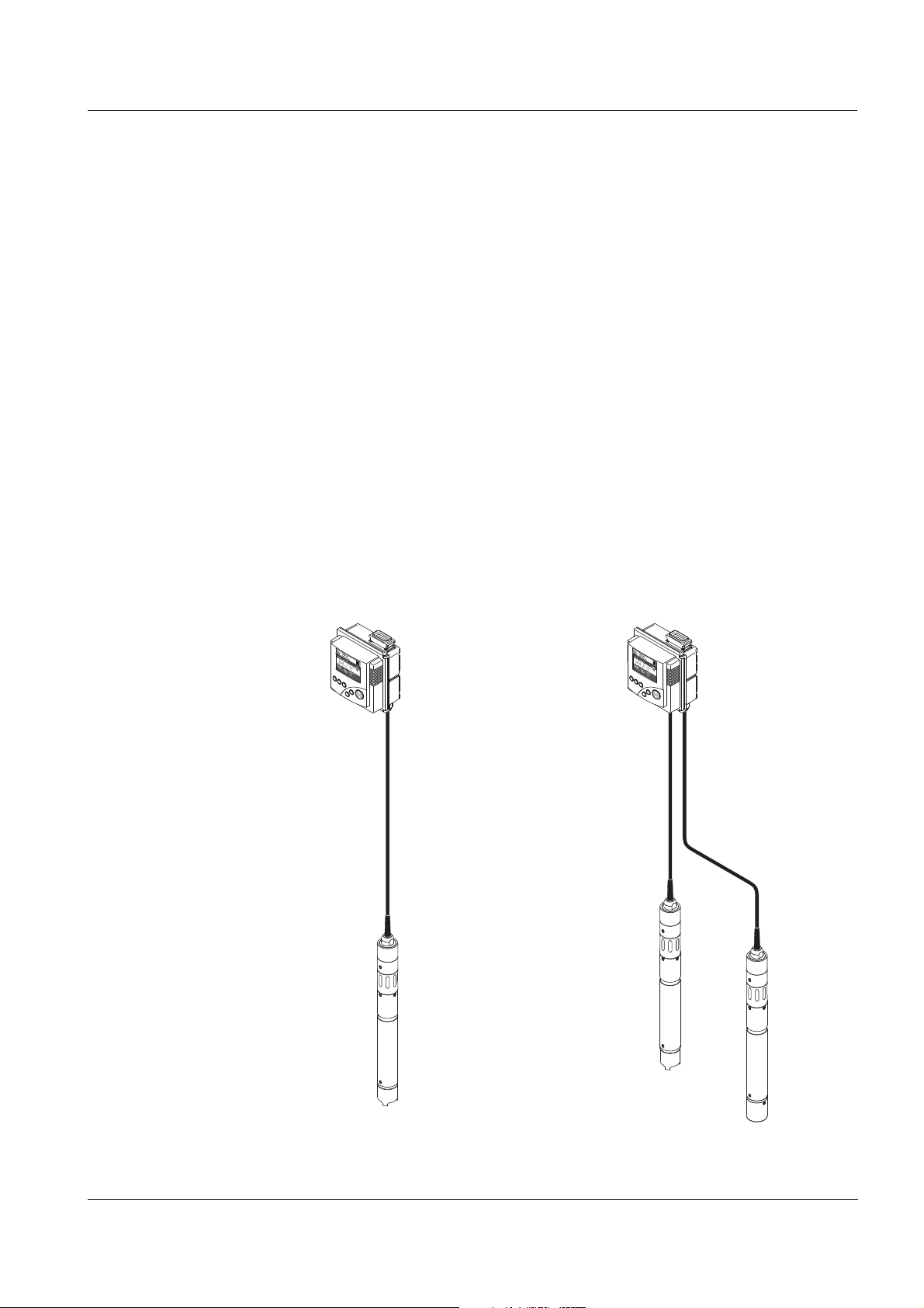
IQ Sensors, digital
Universal Transmitter
DIQ/S 182-PR
1Overview
1.1 Structure and function
The System 182 is a modular, multiparameter measuring system. The
control and operation unit of the system is the DIQ/S 182-PR Universal
Transmitter with integrated power pack. Is has three relay outputs and
a PROFIBUS-DP output for the connection to existing process control
systems.
Sensors One or two digital YSI single sensors (one sensor for one main
measured parameter) or a double sensor (one sensor for two main
measured parameters) can be connected to the DIQ/S 182-PR
Universal Transmitter. I. e. up to two main measured parameters (e.g.
pH, D. O. content, turbidity value...) and additionally up to two
secondary measured parameters (e.g. temperature) can be displayed
and administrated. Each sensor is automatically recognized after being
connected and immediately starts measuring.
The sensors can be directly connected to the DIQ/S 182-PR Universal
Transmitter.
ba76024e01 02/2012
Fig. 1-1 Simple systems with one and two sensors
1 - 1
Page 8

Overview System 182
Relay outputs The relay outputs can be linked to sensors. Linked outputs can be used
to monitor sensors and for the output of measured values.
A relay output is programmable as:
Alarm contact (event monitoring)
Limit monitor
Proportional output of measured values (pulse width or frequency
output)
Control unit of a compressed air-driven sensor cleaning system.
For quick orientation, the states of all relay outputs are clearly indicated
on the display.
PROFIBUS DP output The PROFIBUS output enables a connection to a PROFIBUS master
(PROFIBUS-DP) and thus a connection to a superordinate process
control.
Compressed air-driven
cleaning system
The DIQ/S 182-PR Universal Transmitter is prepared for the
compressed air-driven, time-controlled sensor cleaning function. For
this, a DIQ/CHV valve module and if necessary a CH cleaning head is
required per sensor (both available as accessories). The cleaning
procedure is controlled by the Universal Transmitter. The Universal
Transmitter provides the supply voltage and control relay for the
compressed air valve in the DIQ/CHV valve module. This enables a
simple setup and uncomplicated wiring.
Alternatively, the MIQ/CHV PLUS valve module can be installed in the
system. It combines the relay, valve and valve power supply in one MIQ
enclosure. Thus, no additional wiring is required, which makes
installation easier especially if the distance between the Universal
Transmitter and sensor is great.
Further system options If necessary, an additional power pack can be added to supply sensors
with high power consumption (e.g. UV/VIS sensor).
1 - 2
ba76024e01 02/2012
Page 9

System 182 Overview
1.2 Behavior of the system in the case of power failure
The system configuration remains stored permanently. It consists of
the following settings:
– Sensor settings
– Settings and links of relay outputs
– PROFIBUS settings
– System settings (display language, air pressure/location altitude,
passwords, etc.)
Linked relay outputs switch to the non-active condition (open).
When the power is restored the system is automatically restarted.
The system continues to work with the settings at the time of the
power failure (except for the time).
ba76024e01 02/2012
1 - 3
Page 10

Overview System 182
1 - 4
ba76024e01 02/2012
Page 11
System 182 Safety instructions
2 Safety instructions
This operating manual contains essential instructions that must be
followed during the commissioning, operation and maintenance of the
System 182. Thus, it is essential for the operator to read this
component operating manual before carrying out any work with the
system.
General safety
instructions
Other labels
Safety instructions in this operating manual are indicated by the
warning symbol (triangle) in the left column. The signal word (e.g.
"Caution") indicates the danger level:
Warning
indicates instructions that must be followed precisely in order to
prevent serious dangers to personnel.
Caution
indicates instructions that must be followed precisely in order to
avoid slight injuries to personnel or damage to the instrument or
the environment.
Note
indicates notes that draw your attention to special features.
Note
indicates cross-references to other documents, e.g. component
operating manuals.
Target group The System 182 was developed for online analysis. Some
ba76024e01 02/2012
2.1 User qualification
maintenance activities, e.g. changing the membrane caps in D.O.
sensors, require the safe handling of chemicals. Thus, we assume that
the maintenance personnel is familiar with the necessary precautions
to take when dealing with chemicals as a result of their professional
training and experience.
2 - 1
Page 12

Safety instructions System 182
Special user
qualifications
The following installation activities may only be performed by a
qualified electrician:
Connecting the DIQ/S 182-PR Universal Transmitter or an
additional MIQ power supply module to the power supply.
Connecting external, line voltage-carrying circuits to relay contacts.
2.2 Authorized use
The authorized use of the System 182 consists only of its use in online
analysis.
Please observe the technical specifications according to chapter 10
T
ECHNICAL DATA. Only operation and running according to the
instructions in this component operating manual is authorized.
Any other use is considered to be unauthorized. Unauthorized use
invalidates any claims with regard to the guarantee.
2.3 General safety instructions
All components of the System 182 are constructed and inspected in
accordance with the relevant guidelines and norms for electronic
instruments (see chapter 10 T
They left the factory in a safe and secure technical condition.
ECHNICAL DATA).
Function and
operational safety
The failure-free function and operational safety of the System 182
components are only guaranteed if the generally applicable safety
measures and the special safety instructions in this operating manual
are followed during their use.
The failure-free function and operational safety of the System 182
components are only guaranteed under the environmental conditions
that are specified in chapter 10 TECHNICAL DATA.
If System 182 components are transported from a cold environment
into a warm environment, this can cause a malfunction through the
formation of condensation. In this case, wait for the components to
adjust to room temperature before recommissioning.
2 - 2
ba76024e01 02/2012
Page 13

System 182 Safety instructions
Safe operation If safe operation is no longer possible, the System 182 must be taken
out of operation and secured against inadvertent operation.
Safe operation is no longer possible if components:
have been damaged in transport
have been stored under adverse conditions for a lengthy period of
time
are visibly damaged
no longer operate as described in this manual.
If you are in any doubt, contact the supplier of your System 182.
Obligations of the
operator
The operator of the System 182 must ensure that the regulations and
guidelines listed below are followed when dealing with dangerous
substances:
EEC guidelines relating to safety at work
National laws relating to safety at work
Accident prevention regulations
Safety datasheets of the chemicals manufacturers.
Warning
A circuit (except for power supply connections and relay circuits),
that is connected to the System 182, must not feed any voltages
or currents that are not allowed. It has to be made sure that the
circuit at any time meets all requirements of a Limited circuit or
Limited Power as well as of SELV (Safety Extra Low Voltage).
These include the following limiting value specifications:
AC voltage: max. 30 V effective / 42.4 V peak
DC voltage: max. 60 V
Current limit: max. 8 A
Power output limitation: max. 150 VA
ba76024e01 02/2012
2 - 3
Page 14

Safety instructions System 182
2 - 4
ba76024e01 02/2012
Page 15

System 182 Installation
3 Installation
Note
How to connect the DIQ/S 182-PR to the PROFIBUS master is
described in detail in the chapter 7 PROFIBUS
3.1 Scope of delivery
The following parts are included in the scope of delivery of the
DIQ/S 182-PR:
DIQ/S 182-PR Universal Transmitter
Accessory kit with:
– Contact carrier with screws
– ISO cap nuts with screws and ring washers
– Cable glands with sealing gaskets
CONNECTION.
Operating manual.
3.2 Requirements of the measurement location
The measurement location must meet the environmental conditions
specified in section 10.1 DIQ/S 182-PR.
3.3 Installation guidelines for lightning protection
When using the IQ SENSOR NET instrumentation, particularly in outdoor
areas, adequate protection against (electrical) surges must be
provided. A surge is a summation phenomenon of surge voltage and
surge current. It is generated through the indirect effect of a lightning
event or switching operation in the mains, in the grounding system and
in information technology lines.
To be adequately protected against the damaging effects of surges, an
integrated concept of the following protective measures is required:
internal device-related protective measures and
ba76024e01 02/2012
external protective measures of the installation environment.
The internal device-related protective measures are already integrated
in the YSI online measuring technology as so-called 'lightning
protection' (see chapter 10 T
ECHNICAL DATA).
3 - 1
Page 16

Installation System 182
The external protective measures of the installation environment can
be carried out with respect to the following guidelines:
1 All lines of the IQ S
ENSOR NET system must be
a) installed inside (or else close to) the grounded metallic mounting
constructions, e.g. handrails, pipes and posts if possible
b) or, particularly in the case of longer lines, laid in the ground.
Background: The formation of highly lightning hazardous inductive
loops between the cables and ground is avoided through the low
clearance of the grounded metal construction or by installation in the
ground.
2 Only the SNCIQ or SNCIQ-UG cable material must be used. This
cable material, particularly the high line cross section of the cable
shielding (1.5 mm²), is an important prerequisite for the hazard-free
discharging of the surge without inadmissibly high overvoltages
developing along the line at the same time that could have a
damaging effect on the individual IQ S
ENSOR NET components. It is
not recommended to use cables from other manufacturers with
usually appreciably lower shielding conductor cross sections.
3 All metallic mounting constructions, handrails, pipes, posts etc. on
which MIQ modules are installed must be connected to the local
potential equalization system and the grounding system or must be
individually sufficiently grounded locally according to the codes of
practice.
For the individual grounding of the measuring point the mounting
construction must be solidly connected by means of a large-area
auxiliary electrode with the measuring medium.
Metallic control shafts/pipes and other large-area metallic bodies
that reach into the measuring medium are, for example, ideal for use
in the grounding of the mounting construction.
This creates a set path for the main surge. As a result it is possible
to avoid the surge being discharged via the IQ S
ENSOR NET cable
and via the valuable sensors in the measuring medium.
3 - 2
4 The contacts of the MIQ modules must always be protected by the
associated contact covers if they are not in use. The contact cover
provides improved insulation against the electric fields of a
thunderstorm event through the extension of the air and creepage
paths.
5 It is recommended to attach a metallic or nonmetallic sun shield to
each outside location of the MIQ modules. Sun shields protect the
electric field lines in the area of the MIQ module through an
advantageous development of the electrical field lines in the area of
the MIQ module and promote the dissipation of the surge via the
mounting construction.
6 The mains voltage for supplying the measuring system must comply
ba76024e01 02/2012
Page 17

System 182 Installation
with overvoltage category II. Generally this is ensured through the
public operator of the power supply networks. In company-owned
networks, e.g. in all power supply systems owned by wastewater
treatment plants, this must be kept separate by a potential
equalization and a surge protection system for the plant.
7 One part of the IQ S
ENSOR NET safety and lightning protection
concept is based on high-grade protective insulation of the network
components and of the entire system. It does not have or require
any protective ground (PG) conductor or earth terminal. Avoid any
direct connection of the IQ S
ENSOR NET connections or the metallic
sensor enclosures with the local grounding or potential equalization
system and with metallic construction elements (see point 9).
8 Additional external lightning protection measures directly on the
IQ S
ENSOR NET system or its components, e.g. the use of
overvoltage surge arresters, are not necessary for protection
against the indirect effects of lightning and could possibly result in
malfunctions.
9 For the realization of the internal lightning protection of the system
(e.g. wastewater treatment plant control stands) and for the
protection of IQ S
into buildings or distributions coming from the IQ S
ENSOR NET external resources, cable entry points
ENSOR NET must
be carried out as follows:
– The shield of SNCIQ or SNCIQ-UG cables can be connected to
the local potential equalization with a gas overvoltage surge
arrester. Shielding terminals (e. g. of the PROFIBUS system)
have to be used to contact the shield. The shield of the cable
must not be opened under any circumstances.
– 0/4-20 mA interfaces must be realized with shielded cables. The
cable shield must be connected directly to the potential
equalization(s) provided. If plant potential equalization systems
are provided on both sides, the shield must also be connected on
both sides. The inner conductors must have no contact with the
potential equalization.
– The PROFIBUS cables have to be installed according to the rules
of the relevant bus system.
– Relay lines should be connected to the local potential
equalization in order to provide general and consistent protection
via gas overvoltage surge arresters.
ba76024e01 02/2012
3 - 3
Page 18
Installation System 182
MIQ Module
MIQ Module
DIQ/S 182-PR
MIQ Module
MIQ Module
MIQ Module
DIQ/S 182-PR
MIQ Module
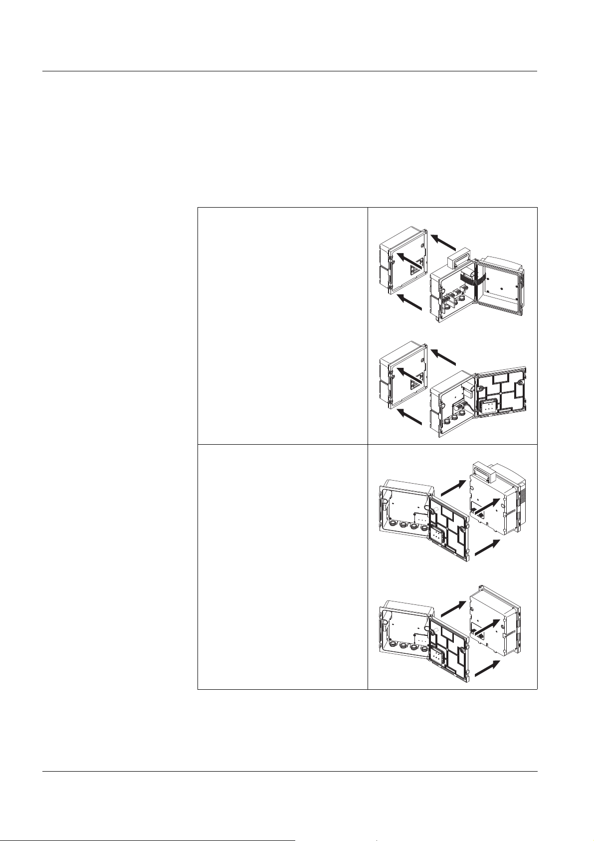
3.4 Connecting system components
3.4.1 Connecting MIQ modules: General information
You can connect the Universal Transmitter to MIQ modules without
connection cable (stack mounting).
Mounting direction
Variant 1 - stack expansion
forwards.
The back of the Universal
Transmitter or an MIQ module is
attached to the lid of an
MIQ module
(page 3-6).
Select this variant if an
MIQ module is already
permanently installed, e.g. to a
wall.
Variant 2: - stack expansion
backwards.
The lid of an MIQ module is
attached to the back of the
Universal Transmitter or another
MIQ module (page 3-9).
3 - 4
Select this variant if the
Universal Transmitter or other
MIQ module is already
permanently installed, e.g. in a
panel.
ba76024e01 02/2012
Page 19

System 182 Installation
Caution
For optimum stability, a maximum of two MIQ modules may be
connected to the Universal Transmitter. One MIQ power supply
module only may be mounted per stack in addition to the
Universal Transmitter.
Note
In the case of panel mounting, the front module must be installed
individually in the switch cabinet aperture first. Only then can any
MIQ modules be added (variant 2).
Note
The terminator switch on the terminal strip of all MIQ modules in the
System 182 must be set to "Off".
Materials required 2 x ISO blind nuts (M4)
2 x cheese-head screws (M4x16) with plastic washer
1 x contact base with two plastic tapping screws (scope of delivery
of the MIQ module).
Tools Phillips screwdriver.
Below, both installation variants of attaching an MIQ module to the
Universal Transmitter are described. The assembly of further MIQ
modules is carried out analogously. To dismantle a stack, proceed in
the reverse order to mounting.
ba76024e01 02/2012
3 - 5
Page 20
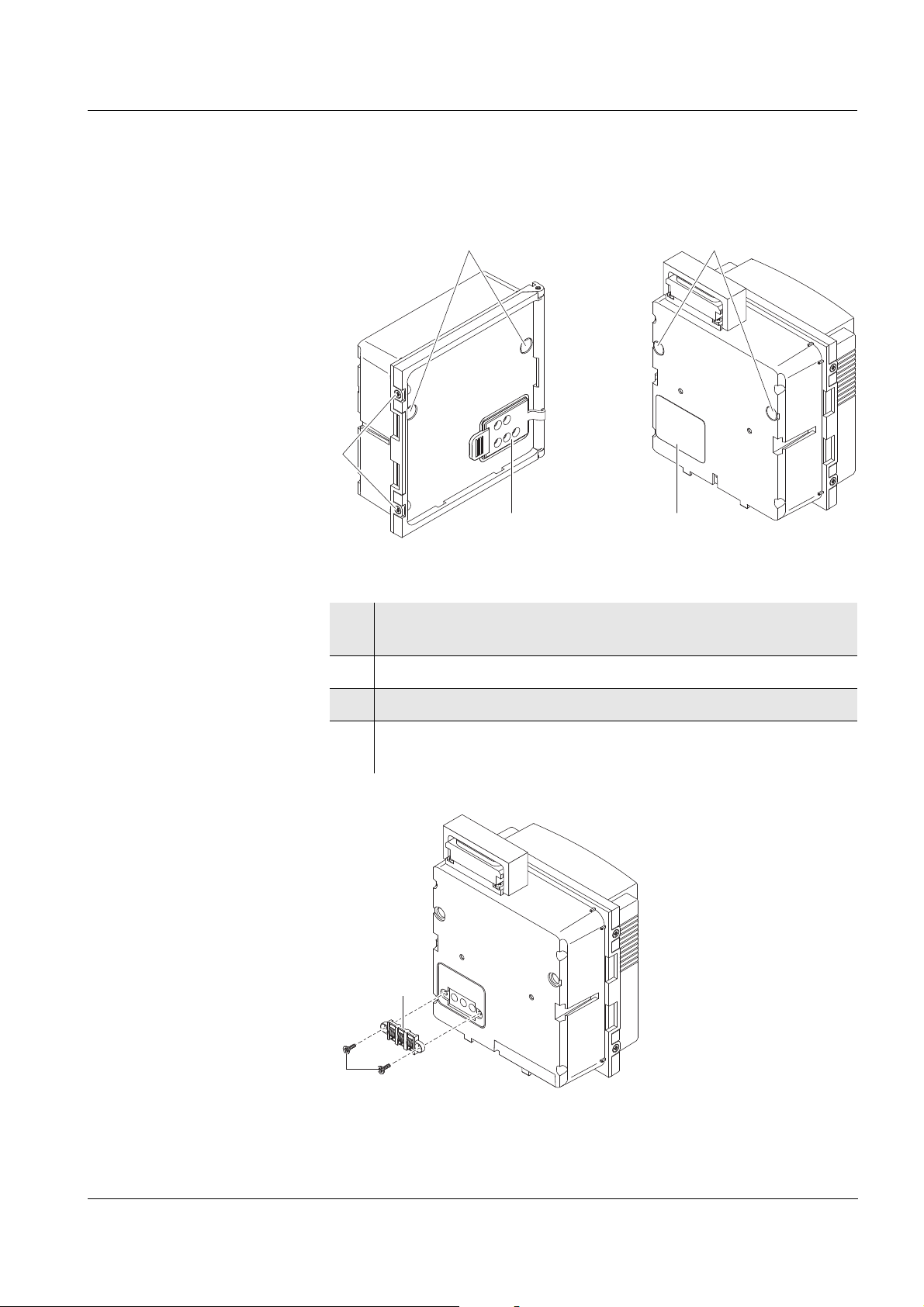
Installation System 182
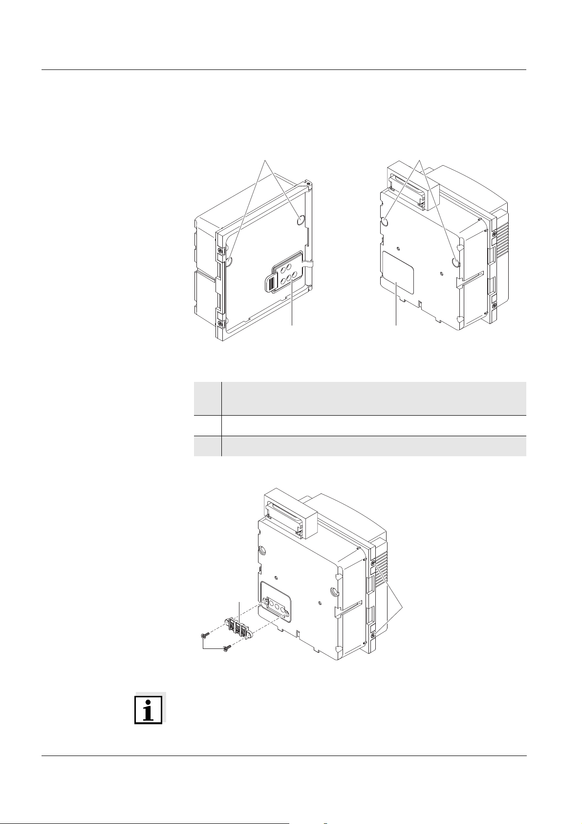
13
24
For stack mounting remove label
and install contact carrier
MIQ module DIQ/S 182-PR
7
5
6
DIQ/S 182-PR
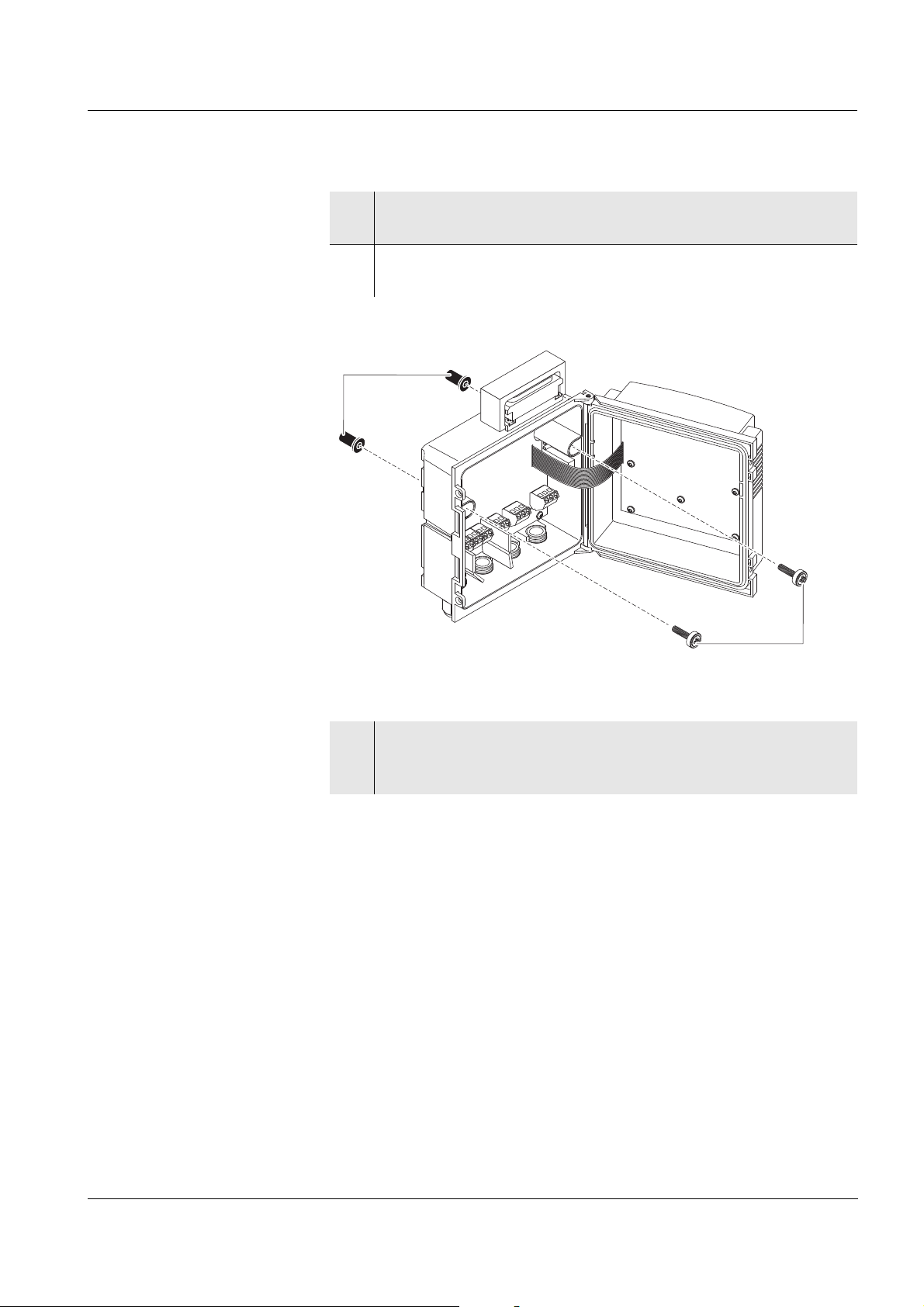
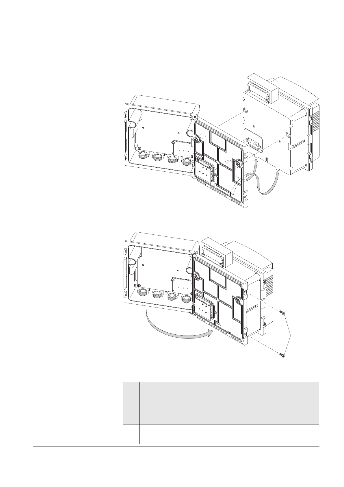
3.4.2 Variant 1: Stack expansion forwards
Preparing the stack
mounting
Fig. 3-1 Preparing MIQ modules for stack mounting (variant 1)
1 Remove the covers from the drilled mounting holes (pos. 1 and
3 in Fig. 3-1).
2 Remove the contact cover (pos. 2).
3 Pull off the adhesive label (pos. 4).
Mounting the contact
base
Fig. 3-2 Mounting the contact base (variant 1)
Note
Only use the plastic tapping screws supplied for attaching the contact
base. They ensure the correct fit.
3 - 6
ba76024e01 02/2012
Page 21
System 182 Installation
9
8
DIQ/S 182-PR
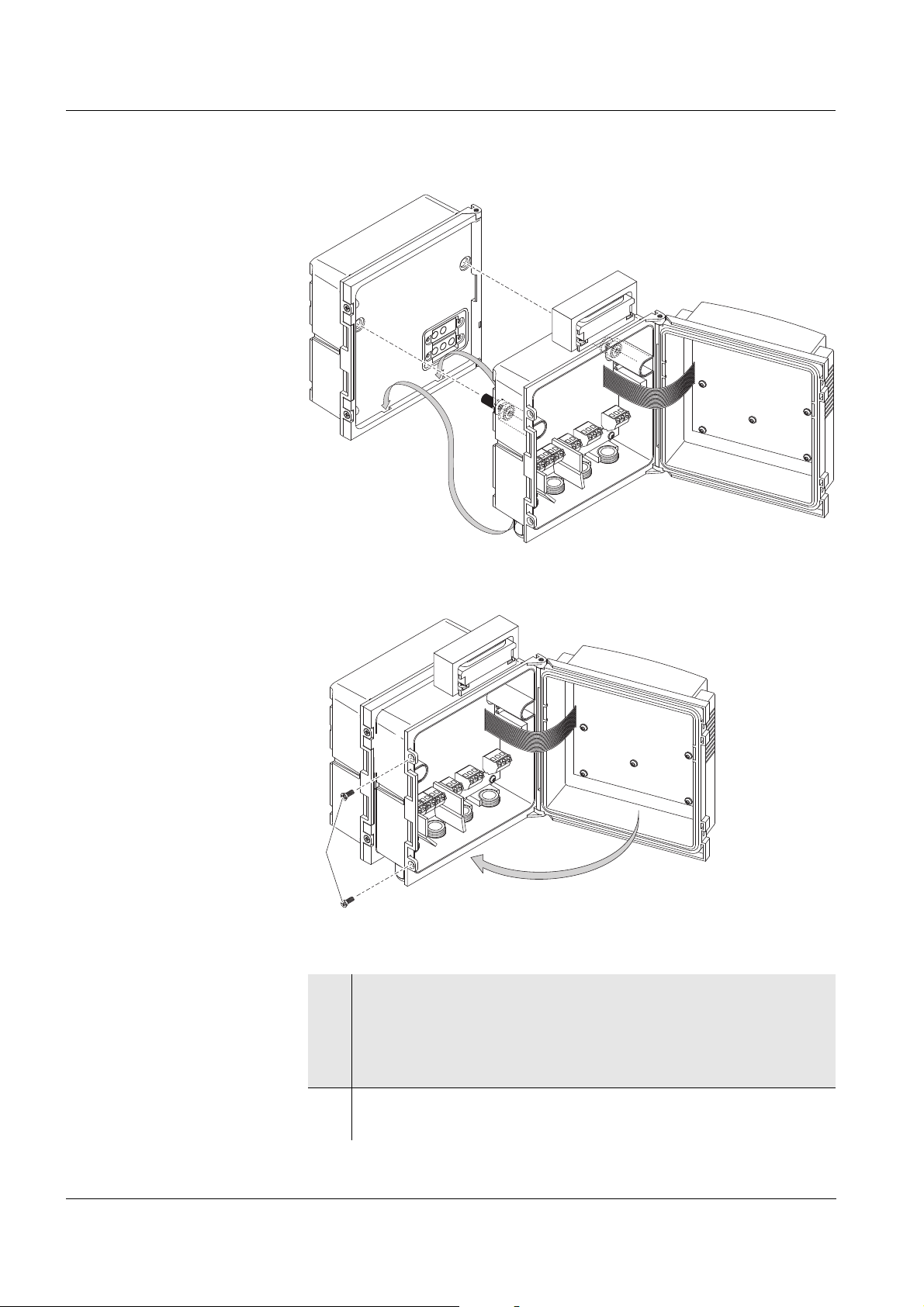
4 Attach the contact base (pos. 5 in Fig. 3-2) on the Universal
Transmitter with the two plastic tapping screws (pos. 6).
5 On the Universal Transmitter, remove the two countersunk
screws (pos. 7 in Fig. 3-2) and swing open the lid.
Premounting the ISO
blind nuts
Fig. 3-3 Premounting the ISO blind nuts (variant 1)
6 Insert the cheese-head screws (pos. 8 in Fig. 3-3) with the
plastic washers in the drilled mounting holes in the enclosure
and loosely screw in the ISO blind nuts (pos. 9).
ba76024e01 02/2012
3 - 7
Page 22
Installation System 182
MIQ module
DIQ/S 182-PR
7
MIQ module
DIQ/S 182-PR
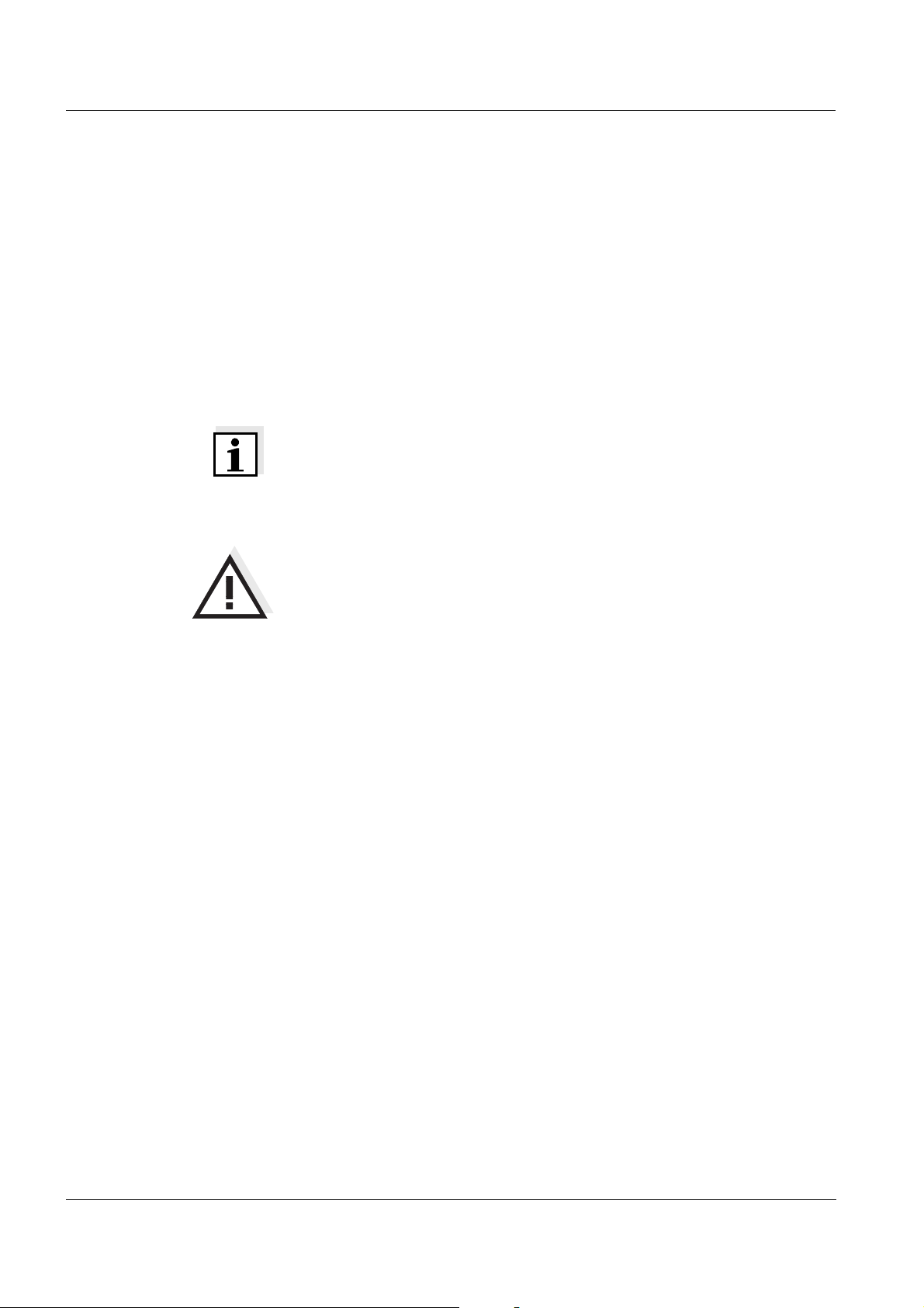
Stacking the
MIQ modules
Fig. 3-4 Stacking the MIQ modules (variant 1)
Fig. 3-5 Closing the enclosure (variant 1)
7 Attach the prepared Universal Transmitter to the lid of the
MIQ module. At the same time, ensure that the two clips on the
Universal Transmitter click into place in the lid of the
MIQ module. Subsequently, tighten the two screws (pos. 8 in
Fig. 3-3).
3 - 8
8 Close the lid of the Universal Transmitter and fix it with the two
countersunk screws (pos. 7 in Fig. 3-5).
ba76024e01 02/2012
Page 23
System 182 Installation
5
13
24
For stack mounting remove label
and install contact carrier
3
4
MIQ module DIQ/S 182-PR
6
7
DIQ/S 182-PR
3.4.3 Variant 2: stack expansion backwards
Preparing the stack
mounting
Fig. 3-6 Preparing the MIQ modules for stack mounting (variant 2)
1 Remove the covers from the drilled mounting holes (pos. 1 and
3 in Fig. 3-6).
2 Remove the contact cover (pos. 2).
3 Pull off the adhesive label (pos. 4).
4 On the MIQ module, remove the two countersunk screws (pos.
5) and swing open the module lid.
Mounting the contact
base
Fig. 3-7 Mounting the contact base (variant 2)
ba76024e01 02/2012
3 - 9
Page 24
Installation System 182
8
9
MIQ module
Note
Only use the plastic tapping screws supplied for attaching the contact
base. They ensure the correct fit.
5 Attach the contact base (pos. 6 in Fig. 3-7) on the Universal
Transmitter with the two plastic tapping screws (pos. 7).
Premounting the ISO
blind nuts
Fig. 3-8 Premounting the ISO blind nuts (variant 2)
6 Insert the cheese-head screws (pos. 8 in Fig. 3-8) with the
plastic washers in the drilled mounting holes in the module lid
and loosely screw in the ISO blind nuts (pos. 9).
3 - 10
ba76024e01 02/2012
Page 25
System 182 Installation
MIQ module
DIQ/S 182-PR
5
MIQ module
DIQ/S 182-PR
Stacking the
MIQ modules
Fig. 3-9 Stacking the MIQ modules (variant 2)
Fig. 3-10 Closing the enclosure (variant 2)
ba76024e01 02/2012
7 Attach the prepared MIQ module to the back of the Universal
Transmitter. At the same time, ensure that the two clips on the
Universal Transmitter click into place in the lid of the
MIQ module. Subsequently, tighten the two screws (pos. 8 in
Fig. 3-8).
8 Close the MIQ module and fix it with the two countersunk
screws (pos. 5 in Fig. 3-10).
3 - 11
Page 26
Installation System 182
3.4.4 Distributed mounting
General information For the locally separated connection between Universal Transmitter
and MIQ modules and between MIQ modules the following cables can
be used:
SNCIQ cable
SNCIQ/UG earth cable - suitable for underground laying in
accordance with VDE 01816, Part 2 and DIN/VDE 0891, Part 6.
The cables are delivered as piece goods (please specify length when
ordering!).
Note
For distances under 2 m, e.g. to connect the Universal Transmitter and
DIQ/JB when installing two sensors in the immediate vicinity of the
Universal Transmitter, any two-wire screened cable can also be used
(wire cross-section > 0.5 mm²)
Caution
The IQ Sensor Net cable may be connected to the SENSORNET
connections only. No wires of the cable may be connected with an
external electrical potential. Otherwise, malfunctions could occur.
General installation
instructions
Materials required 1 x SNCIQ or SNCIQ/UG connection cable (see
Pay attention to the following points when connecting components via
IQ S
ENSOR NET lines:
The sum of all IQ S
ENSOR NET line lengths (SNCIQ, SNCIQ/UG and
SACIQ) in the system may be up to a maximum of 250.
IQ S
ENSOR NET lines must always be installed separately at a
minimum distance of 20 cm from any other lines carrying a voltage
greater than 60 V.
The terminator switch on the terminal strip of all MIQ modules in the
System 182 must be set to "Off".
chapter 12 A
CCESSORIES AND OPTIONS)
Wire end sleeves for 0.75 mm2 wire cross-section with matching
crimping tool
1 x cable gland with seal (scope of delivery of MIQ module).
3 - 12
Tools Cable stripping knife
Wire stripper
Phillips screwdriver
Small screwdriver.
ba76024e01 02/2012
Page 27
System 182 Installation
SNCIQ
SNCIQ/UG
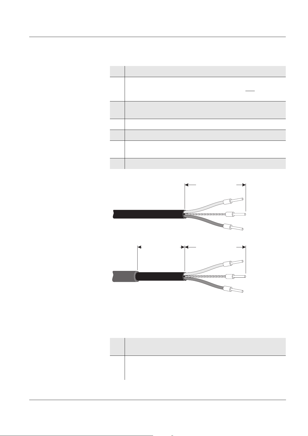
approx. 35 mm approx. 45 mm
approx. 45 mm
Preparing the cable
ends
1 Cut off the cable to the required length.
2 Remove approx. 45 mm of cable insulation (in the case of the
SNCIQ/UG earth cable, remove both the inner and
outer
insulation).
3 Only for the SNCIQ/UG earth cable:
strip the outer insulation for a further 35 mm.
4 Shorten the exposed shielding braid up to the cable sheath.
5 Shorten the two fillers (plastic inlays) up to the cable sheath.
6 Bare the red and green wires and fit them with wire end
sleeves.
7 Fit the filler stranded wire with a wire end sleeve.
Connecting the cables The SNCIQ and SNCIQ/UG cables are connected to the terminal strip
ba76024e01 02/2012
Fig. 3-11 Prepared cable end
in the same way as the SACIQ sensor connection cable (see
section 3.4.5):
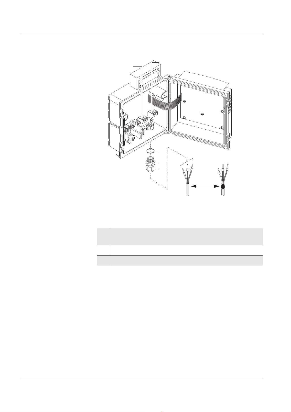
1 Open the enclosure of the Universal Transmitter or
MIQ module.
2 Select a free SENSORNET connection. At the same time, look
out for the SENSORNET designation on the label on the
bottom of the enclosure.
3 - 13
Page 28
Installation System 182
SACIQSNCIQ
SNCIQ/UG
1
3
2
SENSORNET 2
SENSORNET 1
Fig. 3-12 Connecting cables (example of Universal Transmitter)
3 Screw a cable gland (pos. 1 in Fig. 3-12) with the sealing ring
(pos. 2) into the enclosure.
4 Loosen the coupling ring (pos. 3 in Fig. 3-12).
5 Feed the cable through the cable gland into the enclosure.
3 - 14
ba76024e01 02/2012
Page 29
System 182 Installation
SNCIQ(/UG)
or SACIQ
red green
X3 X2 X1
SENSORNET 1
RED
SHIELD
GREEN
Terminal
designation:
Filler stranded wire (SNCIQ...)
or black (SACIQ)
Fig. 3-13 Example: SENSORNET connection
6 Connect the cable ends to the terminal strip. At the same time,
look out for the designations of the terminals (red / shield /
green).
7 Tighten the coupling ring (pos. 3 in Fig. 3-12).
8 Close the enclosure.
Note
The complete assignment of the terminal strip is shown in section 3.12.
ba76024e01 02/2012
3 - 15
Page 30
Installation System 182
3.4.5 Connecting IQ sensors
Sensors can be connected to all free SENSORNET connectors in the
182 system. The Universal Transmitter
DIQ/S 182-PR has two SENSORNET connections.
General installation
instructions
Observe the following points when attaching sensors to the system:
The sum of all IQ S
ENSOR NET line lengths (SNCIQ, SNCIQ/UG and
SACIQ) in the system may be up to a maximum of 250.
IQ S
ENSOR NET lines must always be installed separately at a
minimum distance of 20 cm from other lines that carry a voltage
greater than 60 V.
Materials required 1 x SACIQ connection cable (see chapter 12 A
OPTIONS)
1 x cable gland with seal
The free end of the connection cable already has the sheath removed
in the factory and all the wires are fitted with wire end sleeves.
Tools Phillips screwdriver
Small screwdriver.
Connecting the SACIQ
cable to the Universal
The connection of the SACIQ cable to the terminal strip is described in
section 3.4.4 (see C
ONNECTING THE CABLES, Seite 13).
Transmitter or
MIQ module
CCESSORIES AND
Connecting the sensor
to the connection cable
Caution
The SACIQ sensor connection cable may only be connected to the
SENSORNET connections. No wires of the cable may be
connected with an external electrical potential. Otherwise,
malfunctions could occur.
1 Remove the protective caps from the plug connections of the
IQ sensor and SACIQ sensor connection cable and keep them
safe.
2 Plug the socket of the SACIQ sensor connection cable onto the
plug head connector of the IQ sensor. At the same time, rotate
the socket so that the pin in the plug head connector (1) clicks
into one of the two holes in the socket.
3 Then, screw the coupling ring (2) of the IQ sensor connection
cable on the IQ sensor up to the stop.
3 - 16
ba76024e01 02/2012
Page 31

System 182 Installation
SACIQ
1
2
Fig. 3-14 Connecting the SACIQ cable with the IQ sensor
Note
For further instructions on the mounting of IQ sensors at the application
location, please see the respective manuals (immersion depths, etc.).
ba76024e01 02/2012
3 - 17
Page 32

Installation System 182
3.5 On site mounting of the Universal Transmitter and
MIQ Modules
3.5.1 General information
The DIQ/S 182-PR and the DIQ and MIQ modules have a
comprehensive program of mounting accessories, which can be used
to adapt the installation to the most varied requirements.
Caution
Components installed outside must always be protected by a sun
shield against the effects of the weather (snow, ice and direct
solar radiation). Otherwise, malfunctions can result. Always
mount the Universal Transmitter in an upright position. Do not
under any circumstances install MIQ modules without rain
protection with the lid facing upwards (danger of retained
humidity and penetration of moisture).
Caution
No contact base may be mounted on the back of the module
(danger of short-circuit!) if the module is mounted on a wall, a sun
shield, or a top hat rail.
Installation options The most important types of installation for the Universal Transmitter
are described in the following chapters:
Mounting on a mounting stand with the SSH/IQ sun shield:
The SSH/IQ sun shield provides enough space for the Universal
Transmitter and two MIQ modules (section 3.5.2).
Wall mounting:
The Universal Transmitter or MIQ module is permanently screwed
to a wall. For wall mounting, use the WMS/IQ mounting set (see
chapter 12 A
CCESSORIES AND OPTIONS).
Panel mounting:
The Universal Transmitter or MIQ module is installed in the aperture
of a panel (section 3.5.3).
Top hat rail mounting:
The Universal Transmitter or MIQ module is mounted on a 35 mm
top hat rail with the aid of a bracket, e.g. in a control cabinet. The
connection can be released again with one simple movement
(section 3.5.4).
The following chapters describe the mounting of the Universal
Transmitter. MIQ modules are mounted in the same way.
3 - 18
ba76024e01 02/2012
Page 33

System 182 Installation
2
3
4
1
3.5.2 Mounting on a mounting stand with the SSH/IQ sun shield
Materials required SSH/IQ sun shield (see chapter 12 A
Tools 4 mm set screw wrench
Mounting the sun shield
on a mounting stand
CCESSORIES AND OPTIONS).
Phillips screwdriver.
Fig. 3-15 Mounting the SSH/IQ sun shield on a mounting stand
1 Screw the sun shield (pos. 1 in Fig. 3-15) with the four
hexsocket head screws (pos. 2), the washers (pos. 3) and the
clamps (pos. 4) at the required height on the mounting stand
from the back.
ba76024e01 02/2012
3 - 19
Page 34

Installation System 182
7
6
5
Premounting the ISO
blind nuts
Fig. 3-16 Mounting the sun shield: Premounting the ISO blind nuts
2 Remove the two countersunk screws (pos. 5 in Fig. 3-16) and
swing open the lid.
3 Insert the cheese-head screws (pos. 6 in Fig. 3-16) with the
plastic washers in the drilled mounting holes and loosely screw
in the ISO blind nuts (pos. 7).
3 - 20
ba76024e01 02/2012
Page 35

System 182 Installation
Mounting the Universal
Transmitter on the sun
shield
Fig. 3-17 Mounting the Universal Transmitter on the SSH/IQ sun shield
4 Position the Universal Transmitter on the sun shield and fix it
into place with the two screws (pos. 6 in Fig. 3-16).
5 Close the lid and fix it with the two countersunk screws (pos. 5
in Fig. 3-16).
PROFIBUS cable route Guide the PROFIBUS cable in the sun shield recess behind the
Universal Transmitter to the top of the housing
ba76024e01 02/2012
Fig. 3-18 Universal Transmitter with PROFIBUS cable on the sun shield
3 - 21
Page 36

Installation System 182
138
138
34.5 4711 11
4
Maximum thickness
3mm
3.5.3 Panel mounting
Materials required PMS/IQ kit for panel mounting (see chapter 12 A
OPTIONS).
Tools 3 mm set screw wrench (contained in the panel installation kit).
Switch panel aperture
Fig. 3-19 Mounting aperture in the switch panel (dimensions in mm)
Note
The space required on the panel for the Universal Transmitter is given
in the dimension drawings in section 10.5.
CCESSORIES AND
3 - 22
ba76024e01 02/2012
Page 37

System 182 Installation
F
or sta
ck m
oun
tin
g
re
m
ove
lab
e
l
a
nd
insta
ll con
ta
ct carrier
1
2
3
3
2
Mounting the Universal
Transmitter in the panel
Fig. 3-20 Mounting the Universal Transmitter in the panel
1 Insert the Universal Transmitter in the panel aperture from the
front.
2 Slightly unscrew the screws (pos. 2 and 3) of the two angle
brackets (pos. 1 in Fig. 3-20), but do not remove them.
3 Push in the two angle brackets - as shown in Fig. 3-20 - into
the lateral guides of the Universal Transmitter up to the stop.
4 Tighten the screws (pos. 2).
5 Screw in the screws (pos. 3) until the screws rest snugly
against the panel.
ba76024e01 02/2012
3 - 23
Page 38

Installation System 182
F
o
r sta
ck m
ou
nting
rem
ove
lab
el
a
n
d
insta
ll co
n
tact ca
rrier
1
2
3.5.4 Top hat rail mounting
Materials required THS/IQ kit for top hat rail mounting (see chapter 12 A
AND OPTIONS).
Tools Phillips screwdriver.
Mounting the Universal
Transmitter on a top hat
rail
CCESSORIES
3 - 24
Fig. 3-21 Mounting the Universal Transmitter on a top hat rail
1 Screw the clamping assembly (pos. 1 in Fig. 3-21) onto the
back of the Universal Transmitter with the two plastic tapping
screws (pos. 2).
2 Attach the Universal Transmitter onto the top hat rail from
above using the clamping assembly and press against the rail
until the clamping assembly clicks into place. The Universal
Transmitter can be moved sideways afterwards.
3 To unhook the Universal Transmitter, press it downward and
pull it forward at the bottom.
ba76024e01 02/2012
Page 39

System 182 Installation
3.6 Using DIQ modules (accessories)
Note
The various application possibilities of the DIQ modules are shown by
means of examples in section 3.11.
3.6.1 DIQ/JB
The DIQ/JB module is a passive branching module and can be used for
the following purposes
To extend the SACIQ sensor connection cable, e.g. to connect a
sensor that is located farther away to the Universal Transmitter.
To branch a line at the end of an extension.
Fig. 3-22 DIQ/JB open.
The DIQ/JB module has seven potential free terminals. To extend or
branch lines, connect the three IQ S
ENSOR NET wires to each other
one-to-one at any terminals
green <-> green
red <-> red
black/filler stranded wire <-> black/filler stranded wire.
3.6.2 DIQ/CHV
The DIQ/CHV module is a valve module for the automatic relaycontrolled compressed air-driven cleaning function in the 182 system.
It provides four additional potential free terminals to branch (extend)
interface lines. For each sensor that is to have compressed air cleaning
a DIQ/CHV is required.
ba76024e01 02/2012
3 - 25
Page 40

Installation System 182
Blind nut
Fig. 3-23 DIQ/CHV open.
3.6.3 Installation of the modules
The DIQ module enclosure is designed like a commercial connection
socket and can be mounted directly on a wall. For mounting on a YSI
mounting stand, YSI provides the MS/DIQ mounting set. It contains a
pipe clip for the mounting stand and provides enough space for two DIQ
modules. For assembly use the screws and blind nuts provided with the
MS/DIQ as demonstrated in the following figure
3 - 26
Fig. 3-24 Mounting DIQ modules with the MS/DIQ mounting set.
ba76024e01 02/2012
Page 41

System 182 Installation
sealing ring 20 x 15 x 1 mm
cable gland M16
blind plug
sealing ring 20 x 15 x 1 mm
extension piece M16/M20
sealing ring 24 x 19 x 2 mm
cable gland M20
3.7 Electrical connections: General instructions
Cable glands All electric cables are fed from below via prepared openings in the
enclosure of the DIQ/S 182-PR and the MIQ modules. Cable glands
with different clamping ranges are included with the DIQ/S 182-PR to
provide sealing between the cable and enclosure as well as for strain
relief. Select the matching cable gland for the respective cable
diameter:
Small, clamping range 4.5 to 10 mm. This cable gland is suitable for
all IQ S
outer insulation, see section 3.4.4) and IQ S
connection cable.
ENSOR NET cables (including earth cable after stripping the
ENSOR NET sensor
Large, clamping range 7 to 13 mm. This cable gland is required for
cable sheaths with an outside diameter of more than 10 mm and is
screwed into the enclosure via an extension piece.
Note
If necessary, you can order other sizes of cable gland (see
chapter 12 A
CCESSORIES AND OPTIONS).
ba76024e01 02/2012
3 - 27
Page 42

Installation System 182
General installation
instructions
Observe the following points when attaching connecting wires to the
terminal strip
Shorten all wires to be used to the length required for the installation
Always fit all the ends of the wires with wire end sleeves before
connecting them to the terminal strip
Any wires that are not used and project into the enclosure must be
cut off as closely as possible to the cable gland.
Screw a small cable gland with sealing ring into each remaining free
opening and close it with a blind plug.
Warning
No free wires must be allowed to project into the enclosure.
Otherwise, there is a danger that areas safe to contact could come
into contact with dangerous voltages. This could result in life
threatening electric shock when working with the DIQ/S 182-PR.
Always cut off any wires that are not in use as closely as possible
to the cable gland.
3 - 28
ba76024e01 02/2012
Page 43

System 182 Installation
3.8 Connecting the voltage supply
Note
The two following paragraphs describe how to connect both models of
the DIQ/S 182-PR Universal Transmitter to the voltage supply. How to
connect additional power supply modules is described in the operating
manual of the respective power supply module.
3.8.1 DIQ/S 182-PR (Line power version)
Warning
If the power supply is incorrectly connected, it may represent a
danger to life from electric shock. Pay attention to the following
points during installation:
The DIQ/S 182-PR Universal Transmitter may only be
connected by a trained electrician.
The connection of the DIQ/S 182-PR Universal Transmitter to
the power supply may only be carried out when it is not
carrying any voltage.
The power supply must fulfill the specifications given on the
nameplate and in chapter 10 T
When installed in a building, a switch or power switch must be
provided as an interrupt facility for the System 182.
The interrupt facility must
– be installed in the vicinity of the DIQ/S 182-PR Universal
Transmitter, easily accessible by the user, and
ECHNICAL DATA.
– be labeled as the interrupt facility for the
DIQ/S 182-PR Universal Transmitter.
After the DIQ/S 182-PR Universal Transmitter has been
installed, it may only be opened if the line voltage has been
switched off beforehand.
Materials required Wire end sleeves, suitable for the power line, with suitable crimping
tool
1 x screwed cable gland with sealing ring (scope of delivery of the
Universal Transmitter).
Tools Cable stripping knife
Wire stripper
Phillips screwdriver
Small screwdriver.
ba76024e01 02/2012
3 - 29
Page 44

Installation System 182
approx. 45 mm
L
N
cut ground wire here
Preparing the power
cable
1 Cut off the cable to the required length.
2 Strip the cable insulation for approx. 45 mm.
3 Bare the wires of phases L and N and fit them with wire end
sleeves.
4 If present, cut off the ground wire at the end of the cable
sheath.
Fig. 3-25 Prepared power cable.
Caution
The ground wire must not project into the enclosure. Otherwise,
malfunctions could occur.
3 - 30
ba76024e01 02/2012
Page 45

System 182 Installation
1
3
2
L
N
Connecting the power
line
5 Open the enclosure of the Universal Transmitter.
Fig. 3-26 Inserting the supply line.
6 Screw a cable gland (pos. 1 in Fig. 3-26) with sealing ring (pos.
2) into the enclosure below the power supply connection.
7 Loosen the coupling ring (pos. 3).
8 Feed the power line through the cable gland into the enclosure.
When doing so bend the flexible divider (pos. 4) to the right.
ba76024e01 02/2012
3 - 31
Page 46

Installation System 182
NL
Terminal
labeling:
X17
X16
100...
240V AC
MAINS
L1
N
Fig. 3-27 Line power connection.
Note
The complete assignment of the terminal strip is shown in section 3.12.
9 Connect phases L and N to the terminal strip. Make sure that
the cable assignment agrees with the specification on the
terminal label under the terminal strip.
10 Tighten the coupling ring (pos. 3 in Fig. 3-26).
Warning
No free wires must be allowed to project into the enclosure.
Otherwise, there is a danger that areas safe to contact could come
into contact with dangerous voltages. Always cut off any wires
that are not in use as closely as possible to the cable gland.
11 Close the enclosure of the Universal Transmitter.
3 - 32
ba76024e01 02/2012
Page 47

System 182 Installation
3.8.2 DIQ/S 182-PR/24V (24 V version)
Warning
If the 24 V AC/DC supply is incorrectly connected, it may
represent a danger to life from electric shock. Pay attention to the
following points during installation:
The DIQ/S 182-PR Universal Transmitter may only be
connected by a trained electrician.
The 24 V AC/DC supply must meet the specifications quoted on
the name plate and in chapter 10 T
voltage SELV).
The connection of the DIQ/S 182-PR Universal Transmitter to
the power supply may only be carried out when it is not
carrying any voltage.
When installed in a building, a switch or power switch must be
provided as an interrupt facility for the System 182.
The interrupt facility must
– be installed in the vicinity of the DIQ/S 182-PR Universal
Transmitter, easily accessible by the user, and
ECHNICAL DATA (protective low
– be labeled as the interrupt facility for the DIQ/S 182-PR
Universal Transmitter.
Note
Rechargeable battery systems should have a deep discharge
protection. The DIQ/S 182-PR/24V does not have any built-in deep
discharge protection.
Materials required Wire end sleeves, suitable for the 24 V AC/DC feed line, with
suitable crimping tool
1 x screwed cable gland with sealing ring (scope of delivery of the
Universal Transmitter).
Tools Cable stripping knife
Wire stripper
Phillips screwdriver
Small screwdriver.
Preparing the 24 V AC/
DC line
1 Cut off the cable to the required length.
2 Strip the cable insulation for approx. 45 mm.
ba76024e01 02/2012
3 Bare the wires 1 and 2 and fit them with wire end sleeves.
3 - 33
Page 48

Installation System 182
ca. 45 mm
wire 1
wire 2
1
3
2
Fig. 3-28 Prepared 24 V AC/DC line.
Connecting the 24 V AC/
DC line
4 Open the enclosure of the Universal Transmitter.
3 - 34
Fig. 3-29 Inserting the 24V AC/DC line
5 Screw a cable gland (pos. 1 in Fig. 3-29) with sealing ring (pos.
2) into the enclosure below the 24 V AC/DC connection.
6 Loosen the coupling ring (pos. 3).
7 Feed the 24 V AC/DC line through the cable gland into the
enclosure. When doing so bend the flexible divider (pos. 4) to
the right.
ba76024e01 02/2012
Page 49

System 182 Installation
Terminal
labeling:
X17
X16
24V AC DC
INPUT
POWER
Fig. 3-30 24 V AC/DC connection.
Note
The complete assignment of the terminal strip is shown in section 3.12.
8 Connect wires 1 and 2 to the terminal strip. Make sure that the
cable assignment agrees with the specification on the terminal
label under the terminal strip.
9 Tighten the coupling ring (pos. 3 in Fig. 3-29).
Warning
No free wires must be allowed to project into the enclosure.
Otherwise there is the danger of short circuits that can cause a
fire. Always cut off any wires that are not in use as closely as
possible to the cable gland.
10 Close the enclosure of the Universal Transmitter.
ba76024e01 02/2012
3 - 35
Page 50

Installation System 182
3.8.3 Additional MIQ power supply modules
The power pack of the Universal Transmitter supplies enough power
for most combinations of sensors. Some sensors with high power
consumption may require the installation of an MIQ power supply
module in addition to the Universal Transmitter. For installation, refer to
the operating manual of the power supply module. The table on the
following page shows which sensor/sensor combinations require an
additional power supply module.
Note
The terminator switch on the terminal strip of all additional MIQ
modules in the system 182 must be set to "Off".
3 - 36
ba76024e01 02/2012
Page 51

System 182 Installation
2nd sensor
1st sensor
TriOxmatic
®
700 IQ (SW)
TriOxmatic
®
701 IQ
TriOxmatic
®
702 IQ
FDO
®
70x IQ (SW)
TetraCon
®
700 IQ (SW)
AmmoLyt
®Plus
700 IQ
NitraLyt
®Plus
700 IQ
SensoLyt
®
700 IQ (SW)
ViSolid
®
700 IQ
VisoTurb
®
700 IQ
NitraVis
®
70x IQ *
CarboVis
®
705 IQ *
VARiON
®Plus
700 IQ (NH4-N or NO3-N)
MIQ/IC2 (1 channel operation)
TriOxmatic® 700 IQ (SW)
TriOxmatic® 701 IQ
TriOxmatic® 702 IQ
FDO® 70x IQ (SW)
TetraCon® 700 IQ (SW)
AmmoLyt
NitraLyt
VARiON
(NH4-N or
®Plus
®Plus
700 IQ
®Plus
NO3-N)
700 IQ
700 IQ
SensoLyt® 700 IQ (SW)
ViSolid® 700 IQ
VisoTurb® 700 IQ
--- ------
--- ------
--- ------
--- ------
--- ------
--- ------
--- ------
--- ------
--- ------
--- ------
--- ------
1 1
1 1
1 1
1 1
1 1
1 1
1 1
1 1
1 1
1 1
1 1
--
--
--
--
--
--
--
--
--
--
--
NitraVis® 70x IQ * 1 1 1 1 1 1 1 1 1 1 1 1 1 1
CarboVis
MIQ/IC2
operation)
VARiON
(NH4-N and
MIQ/IC2
(2 channel operation)
NitraVis
CarboVis
NiCaVis
®
70x IQ * 1 1 1 1 1 1 1 1 1 1 1 1 1 1
(1 channel
®Plus
700 IQ
NO3-N)
--- ------
1 1
- (double sensor: no combination with any other sensor possible!)
--
- (double sensor: no combination with any other sensor possible!)
®
70x IQ TS * 1 (double sensor: no combination with any other sensor possible!)
®
70x IQ TS * 1 (double sensor: no combination with any other sensor possible!)
®
70x IQ * 1 (double sensor: no combination with any other sensor possible!)
1 = One additional power supply module required.
* Install a further MIQ power supply module in the vicinity of the MIQ/VIS connection module.
ba76024e01 02/2012
3 - 37
Page 52

Installation System 182
3.9 Connections to the relay outputs
3.9.1 General installation instructions
Warning
If external electrical circuits that are subject to the danger of
physical contact are incorrectly connected to the relay contacts,
there may be a danger of life threatening electric shock. Electrical
circuits are regarded to be subject to the danger of physical
contact when there are voltages higher than the Safety Extra Low
Voltage (SELV).
Pay attention to the following points during installation:
Electrical circuits subject to the danger of physical contact
must only be connected by a qualified electrician.
Electrical circuits subject to the danger of physical contact
must only be connected when they are voltage-free.
If electrical circuits subject to the danger of physical contact
are switched with a relay, no circuit that is not subject to this
danger (e. g. the DIQ/CHV module) may be operated on the
further relays.
Switching voltages and switching currents on the relay
contacts must not exceed the values specified in
chapter 10 T
currents that are too high with an electrical fuse.
Only single-phase consumers can be switched with the relays.
Under no circumstances must multiphase consumers be
switched with the aid of several relays (example three-phase
current driven pumps). Always switch multiphase consumers
via a protective relay.
After the Universal Transmitter has been installed, it may only
be opened if all external voltages have been switched off
beforehand.
ECHNICAL DATA. Protect electrical circuits against
3 - 38
Materials required Wire end sleeves, suitable for the connecting wires, with suitable
crimping tool
4 x screwed cable gland with sealing ring (scope of delivery of the
Universal Transmitter).
Tools Cable stripping knife
Wire stripper
Phillips screwdriver
Small screwdriver
ba76024e01 02/2012
Page 53

System 182 Installation
1
3
2
Connecting lines to the
terminal strip
11 Open the enclosure of the Universal Transmitter.
Fig. 3-31 Inserting lines
Note
The complete assignment of the terminal strip is shown in section 3.12.
12 Screw a cable gland (pos. 1 in Fig. 3-31) with the sealing ring
(pos. 2) into the enclosure below the respective connections.
13 Loosen the coupling ring (pos. 3).
14 Feed the line through the cable gland in the enclosure.
15 Connect the wires to the terminal strip. While doing so, pay
attention to the specifications on the label located under the
terminal strip.
16 Tighten the coupling ring (pos. 3).
ba76024e01 02/2012
3 - 39
Page 54

Installation System 182
X13X15
X6
X12X14
X5
X11X4X10
X3
X9X2X8
X1
Terminal strip
DIQ/S 182-PR
Terminal strip
DIQ/CHV
R1
AUXILIARY
VOLTAGE
VALVEDISTRUBUTION
R2R3
Valve
control line
Warning
No free wires must be allowed to project into the enclosure.
Otherwise, there is a danger that areas safe to contact could come
into contact with dangerous voltages. This could result in life
threatening electric shock when working with the Universal
Transmitter. Always cut off any wires that are not in use as closely
as possible to the cable gland.
17 Close the enclosure of the Universal Transmitter.
3.9.2 Usage of the auxiliary voltage
The Universal Transmitter has a 24 V output (designation,
HILFSSPANNUNG or AUXILIARY VOLTAGE on the terminal strip).
You can use this auxiliary voltage for the relay-controlled opening of the
valve in a DIQ/CHV valve module for the compressed air-driven sensor
cleaning function. To do so, you have to connect the auxiliary voltage
output, a free relay contact and the valve connection in the DIQ/CHV in
series. Bridge a terminal of the auxiliary voltage output with a terminal
of a relay output and run a control line from the remaining terminals to
the valve module.
Caution
The auxiliary voltage must not be used for other purposes.
Connection scheme for one
sensor with compressed air cleaning
3 - 40
ba76024e01 02/2012
Page 55

System 182 Installation
Relais contact
Bridge
Auxiliary voltage output
Valve control line
Separating plate
Caution
Run the bridge below the divider so the bridge does not bump
against the circuit board in the lid when the enclosure is closed.
Note
Installation examples with one and two sensors with compressed air
cleaning can be found in section 3.11.
ba76024e01 02/2012
3 - 41
Page 56

Installation System 182
Start checklist
1 Are all system components correctly connected with one
another (see section 3.4)?
2 Is the Universal Transmitter and all additional power supply
modules correctly connected to the voltage supply (see
section 3.7)?
3 Do the line voltage and line frequency agree with the data on
the name plate of the Universal Transmitter and all additional
power supply modules?
4 Are all IQ sensors ready for measuring, e.g. a D.O. sensor
filled with electrolyte solution?
3.10 Commissioning
Start checklist and
system start
Before starting the system, carry out the system check using the
following checklist. Always carry out the check
before the initial commissioning
before any further commissioning if the system has been previously
extended or modified.
Starting the system Switch on the voltage supply of the Universal Transmitter and all
additional power supply modules. As soon as the system is
successfully initialized, the measured value display appears. In the
case of IQ sensors that are not yet providing measured values, "Init"
appears temporarily
Fig. 3-32 Display during the start phase
Note
Assign a name to each IQ sensor after putting it into operation for the
first time so you can identify it more easily. How to assign a sensor
name is described in section 5.3 on page 5-2.
Note
If the system start failed, see chapter 9 W
HAT TO DO IF ....
3 - 42
ba76024e01 02/2012
Page 57

System 182 Installation
1122334455667
7
SNCIQ(/UG)
SNCIQ(/UG)
(distance > 15 m)
SACIQ
Sensor 2
Sensor 1
Sensor 2
SACIQSACIQ
DIQ/JB
Max. total cable length
SNCIQ(/UG) and SACIQ = 250 m
DIQ/S 182-PR(/24V)
DIQ/S 182-PR(/24V)
MCS
ESC
OK
X1 X4X2 X5X3 X6 X7
Terminal strip
DIQ/JB
SNCIQ(/UG)
green
Shield / Filler stranded wire
black
green
red
red
SACIQ
3.11 Installation examples
3.11.1 Connecting two sensors without compressed air cleaning
Connection scheme of
the DIQ/JB
ba76024e01 02/2012
3 - 43
Page 58

Installation System 182
DIQ/CHV 1
SACIQSACIQ
Valve control line 1
Valve control line 2
AirAir
DIQ/CHV 2
Sensor 2 Sensor 1
Max. total cable length
SNCIQ(/UG) and SACIQ = 250 m
DIQ/S 182-PR(/24V)
M
C
S
ESC
OK
3.11.2 Connecting two sensors with compressed air cleaning
Connection scheme of
valve control
Example:
Relay 1 controls the cleaning of sensor 1.
Relay 2 controls the cleaning of sensor 2.
Variant: Relay 1 controls the cleaning of both sensors. Cleaning of both
sensors is carried out with the same settings.
Warning
In this configuration, the free switching contact (here: R3) may be
used to switch SELV voltages only.
Warning
No free wires must be allowed to project into the enclosure.
Otherwise, there is a danger that areas safe to contact could come
into contact with dangerous voltages. Always cut off any wires
that are not in use as closely as possible to the cable gland.
3 - 44
ba76024e01 02/2012
Page 59

System 182 Installation
X13X15 X12X14 X11 X10 X9
X2
X2
X8
X1
X1
Terminal strip
DIQ/S 182-PR
Variant
Terminal strip
DIQ/CHV 1
Terminal strip
DIQ/CHV 2
R1
AUXILIARY
VOLTAGE
VALVE
VALVE
R2R3
ab c
Valve
control line 1
Valve
control line 2
X13X15 X12X14 X11 X10 X9 X8
R1
AUXILIARY
VOLTAGE
R2
ab c
R3
X6X6X5X5X4X4X3
X3
DISTRUBUTION
DISTRUBUTION
ba76024e01 02/2012
3 - 45
Page 60

Installation System 182
SENSORNET 1SENSORNET 2
RED
RED
SHIELD
SHIELD
GREEN
GREEN
X3X6
X2X5
X17
X9
X15 X13
X11
X1X4
X16 X8
X14 X12
X10
100...
240V AC
MAINS
AUXILIARY
R3
R2
R1
L1
N
240V AC
2A AC
≤
≤
240V AC
2A AC
≤
≤
240V AC
2A AC
≤
≤
AUXILIARY
VOLTAGE
SENSORNET 1
RED
SHIELD
GREEN
X3
X2
X17
X9
X15 X13
X11
X1
X16 X8
X14 X12
X10
24V AC DC
INPUT
POWER
AUXILIARY
R3
R2
R1
240V AC
2A AC
≤
≤
240V AC
2A AC
≤
≤
240V AC
2A AC
≤
≤
AUXILIARY
VOLTAGE
SENSORNET 2
RED
SHIELD
GREEN
X6
X5
X4
1122334455667
7
(7 passive, potential-free terminals
for line extension or branching)
VALVE(AUXILIARY)
X2
X6
X4
X1
X5
X3
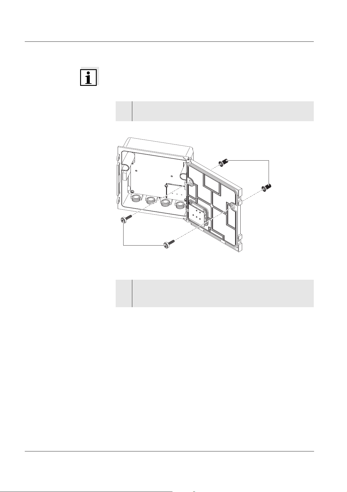
3.12 Figures of the terminal strips
DIQ/S 182-PR
DIQ/S 182-PR/24V
DIQ/JB
DIQ/CHV
3 - 46
ba76024e01 02/2012
Page 61

System 182 Operation
M
C
S
ESC
OK
Display
Key pad
Toggle switch
4 Operation
4.1 Operating elements
Functions
Fig. 4-1 Operating elements of the DIQ/S 182-PR
Key Function
m Switches directly to the measured value display from
all operating situations
c Starts calibration of the sensor selected in the
measured value display
s Opens the SETTINGS menu in the measured value
and status display
e Switches to the higher menu level
Cancels entries without storing them
g Opens the PROPERTIES menu in the measured
value and status display
Confirms an entry
w
(toggle
switch)
Selects:
– The active sensor (measured value display)
– Menu items
ba76024e01 02/2012
– List entries
– Letters or numerals
Scrolls through longer menus or texts
4 - 1
Page 62

Operation System 182
4.2 Measured value and status display
With the m key you switch to the last selected measured value and
status display from any operating situation. Entries that are not
completed are ignored while doing so.
Example:
Display options
with two connected
sensors
By pressing
display options.
m once again you cyclically switch between further
Big double display:
Main measured parameter only.
Detailed double display:
Main and secondary measured
parameter.
Single display.
The display switches between the
connected sensors every
3 seconds.
4 - 2
Display of the interfaces.
Either:
Date and time and the current
states of the relays.
Or (switchable with
State of the PROFIBUS
communication.
Operating notes
Select a sensor in the double display with
is displayed in reverse video. The number and name of the selected
sensor are displayed in the header. In the single display, the sensor
being displayed is always the selected sensor at the same time.
Start a calibration procedure for the selected sensor with
Starting a calibration procedure from the display of interfaces is not
possible.
w. The selected sensor
w):
c.
ba76024e01 02/2012
Page 63

System 182 Operation
Select the PROPERTIES menu with g. With this menu you can put
sensors in the maintenance condition and prompt important data
(calibration data, error messages, operating states, software
versions, etc.).
Open the SETTINGS menu with
Special
The following displays inform you of special states of sensors
sensor conditions
Init Sensor is being initialized
during commissioning or
if a new IQ sensor is recognized that is not yet
---- Sensor inactive or inadmissible operating conditions
Cal Sensor is being calibrated
Clean Cleaning procedure active
Error No communication with the sensor due to defective
connection
OFL Measuring range undercut or exceeded (overflow)
Display
Sensor in maintenance condition
flashes
Error and info symbol If the info symbol
messages from the sensors or error conditions of the system have
occurred. Error messages from the sensors are entered in the log book.
The log book is described in detail in section 4.4.3. Error conditions of
the system can e.g. be an insufficient operational voltage or
malfunctions of the communication and are displayed in the
PROPERTIES / SYSTEM STATUS menu (see section 4.4.1).
s.
giving measured values
i or error symbol h appears in the header, error
ba76024e01 02/2012
4 - 3
Page 64

Operation System 182
4.3 Working with the SETTINGS menu
Note
All settings in the SETTINGS menu can be protected by a password
against unauthorized changing. For more detailed information on
password protection, see section 4.6.
4.3.1 Selection menus
Pressing
SETTINGS menu (main menu).
Fig. 4-2 SETTINGS menu (main menu)
Operating notes
In the main menu, the lock symbol shows the current safety level for
the settings
–
–
For more detailed information on password protection, see
section 4.6.
The arrows 8/2 appear automatically if further display contents are
above or below the visible display range.
S switches from the measured value display to the
a Settings not protected by password
z Settings protected by password (reading possible only)
4 - 4
With the toggle switch
reverse video) and move the visible display range up or down.
To open a menu item, highlight it and press
switches to a further submenu or to a setting table.
To return to the measured value display, press
w you highlight a menu item (displayed in
g. The display
m or e.
ba76024e01 02/2012
Page 65

System 182 Operation
4.3.2 Setting tables
In the setting tables, you make the actual settings. Two lines together
represent each setting. The name of the setting is in the upper line on
the left side of the display. The corresponding value is in the line below
on the right side.
Fig. 4-3 Example of a setting table
Operating notes
The arrows 8/2 appear if further display settings are above or
below the visible display range.
With the toggle switch
reverse video) and move the visible display range up or down.
To edit a setting highlight it and press
highlighted and switches to the entry mode. Depending on the
operating situation, a new submenu or a table with further relevant
settings can open up.
Break off an action and change to the next higher level with the
key.
Move directly to the measured value display with
Note
To accept all settings, you have to highlight the Save and quit menu
item at the lower end of the setting table and press
setting table via
changes are ignored.
m, e/Beenden or the Beenden menu item, all
w you highlight a setting (displayed in
g. The line below is
e
m.
g. If you exit the
ba76024e01 02/2012
Fig. 4-4 Save and quit
4 - 5
Page 66

Operation System 182
4.3.3 Entry mode
In the entry mode, you can change individual values or enter a
character string. Depending on the value type, change a value as
follows
Fixed values of a selection list (e.g. sensor measuring ranges):
This is the most frequent form of an entry. Select the required option
with the toggle switch
display switches back to the setting table.
Fig. 4-5 Example of a selection list
w and confirm the selection with g. The
Character strings (text and numerals):
The following letters, numerals and special characters can be
entered: AaBb..Zz0..9µ%&/()+-=><!?_ °.
Entries are made character after character. Select the first character
with the toggle switch
the next position and indicates
toggle switch
of characters select
entry is completed with this and the display switches back to the
setting table.
Fig. 4-6 Example of text entry
w. When you have selected the required sequence
w and press g. The entry mark moves to
P. Select the next character with the
P as the following character and press g. The
4 - 6
ba76024e01 02/2012
Page 67

System 182 Operation
If you want to correct a previously selected character while entering,
select the thin arrow to the left b and press
entry mark by one digit to the left. Thus you can go back to the
required character. All characters on its right side, however, have to
be entered once again.
If you want to restart entering the characters, select the thick arrow
to the left B and press
Numerals:
Entering numerals is made in the same way as entering characters.
The following numerals can be entered: 0..9-.
Entering" -" or "." is only allowed where it makes sense, e.g. "-" at
the first position only.
Save and quit On principle, all settings done in the entry mode are only taken over
after you selected the Save and quit item in the relevant setting table
and pressed
menu item, all changes are ignored.
Exceptions: Date/time, air pressure and password.
g. If you exit the setting table via m, e or the Quit
g.
g. This moves the
ba76024e01 02/2012
4 - 7
Page 68

Operation System 182
4.4 PROPERTIES menu
4.4.1 Overview
Pressing
g switches from the measured value display to the
PROPERTIES menu.
In the PROPERTIES menu, you can prompt calibration data and
various information on system components. Moreover, you can switch
on and off the maintenance condition of a sensor.
Fig. 4-7 PROPERTIES menu
Submenus/functions Maintenance Sensor SXX With this function, you switch on and off
the maintenance condition of a sensor (see section 4.4.2)
Sensor status Sxx
Here you can prompt the following data of a sensor (see
section 4.4.3):
– Type, series number and software version
– Data of the last calibration
– Error and info messages
System status
Here you can prompt the following data of the system:
– Series number and software version of the Universal Transmitter
– Status of the operational voltage ( = OK / = faulty)
– Status of communication ( = OK / = faulty)
– Current states of interfaces
If the operational voltage or communication are faulty, the flashing
error symbol
display. The error symbol
h appears in the header of the measured value
h automatically disappears when the
malfunction has been eliminated.
List of components
Here is a list of all connected sensors and MIQ/VIS connection
modules.
4 - 8
ba76024e01 02/2012
Page 69

System 182 Operation
= Maintenance condition ON
gme//
m
c
e/m
g
c
g
Measured value
display
The measured value
stops flashing
Measured value
display
The measured
value flashes
Measured value
display
flashes
Clean
Calibration
Step 1
Calibration
Step n
End
Maintanance
condition ON
manually
Maintanance
condition OFF
manually
Sensor
cleaning
active
Sensor
cleaning
OFF
(automatic sequence)
= Maintenance condition OFF
e
Switch
Display message:
on the
maintenance
condition
Continue/Cancel
4.4.2 Maintenance condition
When an IQ sensor is calibrated, cleaned, serviced or repaired, the
maintenance condition for the relevant IQ sensor should always be
switched on.
In the maintenance condition
apart from the measured value display, the system does not react to
the current measured value or the condition of the selected
IQ sensor
IQ sensor errors do not prompt changes in the conditions of linked
outputs.
The following diagram gives you an overview of when an IQ sensor is
in the maintenance condition.
ba76024e01 02/2012
4 - 9
Page 70

Operation System 182
Recommended
proceeding for cleaning,
maintenance and repair
Automatic switch-on of
the maintenance
condition
1 Switch on the maintenance condition for the IQ sensor. The
measured value display flashes.
2 Pull the sensor out of the sample.
3 Carry out the cleaning, maintenance or repair (removal and
replacement) of the sensor.
4 Submerse the sensor in the sample again.
5 Wait until the measured value does no longer change.
6 Switch off the maintenance condition for the sensor. The
display of the sensor in the measured value display does no
longer flash.
The maintenance condition for IQ sensors is automatically activated
during calibration. After calibration the IQ sensor remains in the
maintenance condition until the maintenance condition is switched
off manually (see section 4.5)
during a compressed-air cleaning cycle. After the cleaning cycle is
finished the maintenance condition is automatically switched off
again.
4 - 10
ba76024e01 02/2012
Page 71

System 182 Operation
4.4.3 Sensor status Sxx
In the SENSOR STATUS Sxx menu you can prompt the following
information on a sensor:
Type and series number
Software status
Error and info messages ("log book")
Data of the last calibration (only for sensors that can be calibrated)
Fig. 4-8 SENSOR STATUS Sxx
Log book The log book is a list of messages related to a sensor. If there is a new
message the info or error symbol in the header of the measured value
display flashes:
h
Flashes if a new or unacknowledged error message is present
in the log book that requires immediate action.
i
Flashes if a new or unacknowledged informational message is
present in the log book.
If there are info and error messages present at the same time, the error
symbol
h flashes (more important).
The flashing of the info or error symbol only stops after all detailed
message texts in the log book have been opened and marked with a
tick (). The operating sequence to do this is described on page 4-13.
Note
The error symbol also flashes if the operational voltage or
communication in the system are faulty. You can check this in the
PROPERTIES / SYSTEM STATUS menu (see section 4.4.1).
ba76024e01 02/2012
4 - 11
Page 72

Operation System 182
12 3
Calibration data You can view the data of the last calibration under the Cal menu item.
Sensors that have not yet been calibrated do not have this menu item.
The symbol in the Cal line quotes the validity state:
= valid
= invalid
The content and form of the calibration data depend on the sensor type.
Log book messages Each log book message in the log book consists of one line. The latest
message is on the first position. They are not yet marked with a tick, i.e.
acknowledged.
Fig. 4-9 Log book
1 Message type (error or info symbol) of an unacknowledged
message,
or tick () with an acknowledged message
2 Message code
3 Date and time of the message
Note
The log book shows the current status at the point of time it was
opened. If new messages arrive while the log book is open, these do
not appear in the log book. The new messages are only included when
you switch to the measured value and status display.
4 - 12
ba76024e01 02/2012
Page 73

System 182 Operation
Category
Type
Type number
II2
Structure of the
message code
Fig. 4-10 Message code
Pos. Information Explanation
1 Category Info message (I)
Error message (E)
2Type Calibration (C)
Installation and commissioning (I)
Instructions for service and repair (S)
Application instructions (A)
3 Type number Each type contains subtypes (0..9A..Z)
Note
Only the last message of each message code is ever displayed. If a
new message arrives with a message code that already exists in the log
book, the older message is overwritten.
Detailed message text You can view the detailed message text when you acknowledge the
message. It contains a precise description of the message codes and,
if required, instructions for any further actions. The detailed message
texts can also be found in the respective sensor operating manual.
Proceeding:
Open log book,
acknowledge messages
and view detailed
messages
1 Open the PROPERTIES menu.
To do so, press
g in the measured value display.
ba76024e01 02/2012
2 Select Sensor status Sxx (xx = required sensor) and press g.
4 - 13
Page 74

Operation System 182
3 Select the Log... menu item and press g.
The log book is displayed.
4 Highlight the message to be acknowledged and press g. The
detailed message text is displayed. Scroll through the text with
the toggle switch
5 Press g. Thus you acknowledge the message ().
w.
4 - 14
6 Press g once again. With this you return to the log book and
can view and acknowledge further messages as necessary.
7 To exit the log book press
Return directly to the measured value and status display with
e.
m.
ba76024e01 02/2012
Page 75

System 182 Operation
4.5 Calibration of sensors
Note
Sensors can be protected by a password against unauthorized
calibration. For more detailed information on password protection, see
section 4.6.
General proceeding
1 Switch to the measured value display with m.
2 Select the sensor to be calibrated with
display, the sensor being displayed is always selected at the
same time).
3 Call up calibration with c.
The message, During the calibration procedure, the linked
outputs are frozen, appears. The maintenance condition is
switched on the next time the
measured value display without switching on the maintenance
condition with
Note
By activating the maintenance condition, linked outputs remain in their
present state. The measured value or status display of the sensor
flashes in the measured value display.
m or e.
g key is pressed. Return to the
W (in the single
ba76024e01 02/2012
4 Confirm with g. The maintenance condition is active.
The following proceeding is sensor type specific.
The display guides you through all steps.
Exactly follow the instructions.
A message of the success of the calibration and the
determined calibration data appear at the end.
Note
Up to this point you can cancel the calibration procedure with the
key at any time. The system continues to work with the old calibration
data. The maintenance condition, however, has to be switched off
again in any case.
e
4 - 15
Page 76

Operation System 182
5 Confirm the calibration data with g. Calibration is completed
with this. The following display message describes the further
steps to put the sensor into operation again.
Putting the sensor into
operation after
calibrating
6 Confirm with g. The display returns to the measured value
display (the measured value flashes as the sensor is still in the
maintenance condition).
7 If calibration was successful, immerse the sensor in the test
sample.
8 Wait for a stable measured value.
9 Switch off the maintenance condition (highlight sensor and
press
g three times). The measured value has stopped
flashing.
Note
If calibration was not successful, this is indicated by "----" on the display
and a corresponding message with remedial actions appears in the log
book. Follow the instructions and repeat calibration.
4 - 16
ba76024e01 02/2012
Page 77

System 182 Operation
4.6 Passwords
You can assign and activate two passwords for the System 182.
Settings password
protects all settings in the SETTINGS menu.
If the password is active, all settings can be viewed but not changed.
The password query appears on leaving a setting table with the
Save and quit command. Resetting the system configuration to
default is also protected.
Calibration password
protects against unauthorized calibration.
If this password is active, the password query appears on calling up
calibration with
blocked.
c. If no valid password is entered, calibration is
Configuring
passwords
Activating/deactivating and changing passwords is done in the
SETTINGS -> System menu.
Fig. 4-11 SYSTEM SETTINGS menu
Operating notes
The settings password is configured with the Settings
a / z menu
item.
The calibration password is configured with the Calibrate
a / z
menu item.
Any activating, deactivating or changing action requires the entry of
the relevant current password.
ba76024e01 02/2012
4 - 17
Page 78

Operation System 182
4 - 18
ba76024e01 02/2012
Page 79

System 182 The SETTINGS menu
To view these menu items, scroll
down with
w.
5The SETTINGS menu
5.1 Overview of the SETTINGS menu
Pressing S switches from the measured value display to the
SETTINGS menu (main menu).
Fig. 5-1 Submenus in the SETTINGS menu
Proceeding: selecting
the language
The individual submenus are described in the following paragraphs.
Note
The entire system configuration can be saved on a PC and loaded back
from there with the aid of the MIQ/IF232 interface module and the ConfigSaveLoad PC software. ConfigSaveLoad is part of the IQ Softwarepack and as such included in the scope of delivery of the MIQ/IF232.
More detailed information is given in the operating manual of the IQ
Softwarepack, which can be downloaded under www.ysi.com
.
5.2 Language
In this menu, you can set the system language.
1 Open the SETTINGS menu with s.
2 Select and confirm the Language menu item with
The LANGUAGE display opens.
w and g.
ba76024e01 02/2012
5 - 1
Page 80

The SETTINGS menu System 182
3 Select the required language from the list with w and confirm
g. The selection is taken over immediately. The display
with
switches to the higher menu level.
4 Switch to the measured value display with
m.
Note
If the selected system language is not available in a sensor, all displays
of this sensor appear in the standard language English. To activate the
selected system language for this component, a software update of the
component is required. Contact YSI.
5.3 Sensor S01/S02
In this menu, you can assign a name of your choice to a sensor and
adjust the sensor so it optimally meets the requirements of your
application (measured parameter, measuring range, etc.).
All settings are specific for the respective sensor type. They can only
be modified if the sensor is connected and communicates with the
Universal Transmitter properly. Otherwise, the dataset is inactive. How
to deal with inactive datasets is described below.
Note
General steps for editing sensor settings are given below. The
Sensorname menu item is always on the first position of the setting
table. Details of further sensor settings can be found in the chapter,
C
OMMISSIONING of the sensor operating manual.
Proceeding:
carrying out settings
5 - 2
5 Open the SETTINGS menu with s.
6 Using
w and g, select and confirm the Sensor S0x menu
item (corresponding to sensor 1 or sensor 2).
The following note appears:
If the measuring mode or measuring range is changed, the
links of the sensor are erased.
7 If you want to continue press g.
The setting table of the sensor is displayed.
ba76024e01 02/2012
Page 81

System 182 The SETTINGS menu
8 Edit the setting table as described in section 4.3.2.
Note
To accept all settings, you have to highlight the Save and quit menu
item at the lower end of the setting table and press
setting table via
changes are ignored.
Inactive sensor datasets An inactive dataset for an IQ sensor arises if the Universal Transmitter
receives no signals from an already registered IQ sensor. The Error
display appears on the measured value display instead of a measured
value.
m, e/Beenden or the Beenden menu item, all
g. If you exit the
Proceeding: deleting
inactive datasets
An inactive dataset can be reactivated by assigning it, e.g. to an IQ
sensor of the same type (see section 9.3.2). All settings are retained. If
you no longer require these data, you can erase them. All the settings
belonging to this IQ sensor as well as any links with outputs are deleted
by this action.
1 Open the SETTINGS menu with s.
2Using
item (corresponding to sensor 1 or sensor 2).
If the dataset is inactive the following display appears:
3 Select Delete dataset with d and confirm with g.
The dialog window for the security prompt appears.
w and g, select and confirm the Sensor S0x menu
ba76024e01 02/2012
4 Select Delete dataset with
The inactive sensor is erased.
d and confirm with g.
5 - 3
Page 82

The SETTINGS menu System 182
5.4 Relay output R1/R2/R3
In these menus you can link sensors with the relay outputs of the
Universal Transmitter and adjust the outputs. The various setting
options are described in detail in the chapter 6 R
ELAY OUTPUTS menu.
5.5 PROFIBUS config.
You can set the PROFIBUS address in this menu (proceeding, see
section 7.3). All information needed to connect the DIQ/S 182-PR to a
PROFIBUS plant is given in chapter 7 PROFIBUS
CONNECTION.
5.6 System
The settings in the SYSTEM menu comprise:
Date/Time
Pressure/Altitude
This setting is important if you want to carry out D. O. measurements
with the System 182.
(adjustable range: 500 ... 1100 mbar or 0 ... 5955 m altitude).
Settings
a / z?
Here you can configure the password for the settings.
For details on the passwords refer to section 4.6.
Calibrate
a / z?
Here you can configure the password for calibration.
For details on the passwords refer to section 4.6.
Display contrast
Here you can set the display contrast for optimum readability.
Delivery state
Here you can reset all settings to default. Only the date, time and
contrast setting for the display will remain stored. If the settings
password is active, a password prompt appears before the reset. In
any case a security prompt appears to prevent an inadvertent reset.
5 - 4
ba76024e01 02/2012
Page 83

System 182 The SETTINGS menu
Delivery condition
Settings Default values
Language English
Pressure/Altitude 1013 mbar / 0 m
Settings password 1000 / inactive
Calibration password 1000 / inactive
Sensor settings Sensor dependent (see settings
tables in the respective sensor
operating manual).
Calibration of the sensor is
Note:
stored in the sensor and is
retained when the system
configuration is reset.
Relay outputs no function, all links are erased
PROFIBUS address 20
ba76024e01 02/2012
5 - 5
Page 84

The SETTINGS menu System 182
5 - 6
ba76024e01 02/2012
Page 85

System 182 Relay outputs
6 Relay outputs
6.1 General information
The DIQ/S 182-PR Universal Transmitter has three relay outputs and
one PROFIBUS output.
Functions for relay
outputs
System monitoring
Sensor monitoring
Limit indicator
Frequency output
Pulse-width output
Sensor controlled
Cleaning
Manual control
Relay outputs can be configured as opener or closer.
Note
You can view the current states of the relay outputs in the measured
value and status display (see section 4.2).
ba76024e01 02/2012
6 - 1
Page 86

Relay outputs System 182
6.2 Linking and adjusting: general proceedings
6.2.1 Linking relay outputs
Linking options You have the following options of linking relay outputs:
Sensor S01
The output is linked with sensor 01
Sensor S01
The output is linked with sensor 02
Sensor S01&S02
The output is linked to both sensors S01 and S02.
System
Select this option if you want to use the output for system monitoring
(details, see section 6.4.2).
Proceeding: linking
outputs
Proceed as follows if the output was not yet linked. If you want to
change a link you have to erase the existing link first.
1 Open the SETTINGS menu with s.
2 Using
w and g, select and confirm the Relay output Rx
menu item (corresponding to sensor 1, 2 or 3). A list with all
linking options is displayed.
3 Select the required option with w and confirm with g.
The output is linked. The link is displayed in the header when
the setting of the output is edited.
6 - 2
ba76024e01 02/2012
Page 87

System 182 Relay outputs
6.2.2 Deleting a link with an output
If you no longer need a link you can erase the link.
Proceeding: erasing a
link
1 Open the SETTINGS menu with s.
2Using
w and g, select and confirm the Relay output Rx
menu item (corresponding to sensor 1, 2 or 3).
3 Using w, select Delete link and confirm with g.
A security prompt appears.
4Using
w, select Delete link and confirm with g.
The link is deleted.
ba76024e01 02/2012
6 - 3
Page 88

Relay outputs System 182
6.2.3 Setting outputs
Proceeding: setting an
output
1 Open the SETTINGS menu with s.
2 Using
menu item (corresponding to sensor 1, 2 or 3).
3 Confirm the selection Set output with g.
The setting table of the output is displayed.
w and g, select and confirm the Relay output Rx
4 Edit the setting table as described in section 4.3.2.
Note
To accept all settings, you have to highlight the Save and quit menu
item at the lower end of the setting table and press
setting table via
ignored.
m, e/Quit or the Quit menu item, all changes are
g. If you exit the
6 - 4
ba76024e01 02/2012
Page 89

System 182 Relay outputs
6.3 Basic information on relay functions
In this chapter, you will find general basic information concerning the
following relay functions:
Event monitoring (see section 6.3.1)
Limit indicator (see section 6.3.2)
Proportional output (see section 6.3.3)
6.3.1 Event monitoring
When using a relay for event monitoring, a relay action (Open, Close)
occurs when the monitored event takes place.
This function is suitable, e.g. for the monitoring of errors in the system.
If an event takes place, the relay works as an alarm contact.
Note
For monitoring functions, use the relay preferably as an opener. In the
case of an error, the relay opens. As a result, the monitoring function
operates even if, e.g. the supply voltage fails.
6.3.2 Limit indicator
With a limit indicator, a relay switches when a specified limiting value is
exceeded or undercut.
Limit indicators can be used in the following way:
Monitoring a limiting value using a relay:
when a limiting value (upper or lower limiting value) is exceeded or
undercut, a relay switches. The Open or Close relay actions are
possible in each case (see page 6-6).
Monitoring two limiting values using two relays:
If the upper limiting value is exceeded or undercut, a relay switches,
and if the lower limiting value is exceeded or undercut, another relay
switches. The Open or Close relay actions are possible in each case
(see page 6-6).
Note
If the simple monitoring function (Open, Close) with one or two relays
is not sufficient, use proportional output (see section 6.3.3).
ba76024e01 02/2012
6 - 5
Page 90

Relay outputs System 182
Time
Measured
value
UL
LL
Hysteresis UL
Hysteresis LL
3
5
Relay 1
Relay 2
4
1
2
t1
t1
6
t2 t2
Monitoring limiting
values using one or two
relays
Fig. 6-1 Switching points for relays with the function of a limit indicator
1 Upper limit value (relay 1) exceeded
2 Selected switching delay t1 for relay 1 expired
Relay 1 switches
3 Hysteresis for upper limiting value (relay 1) undercut
4 Selected switching delay t1 for relay 1 expired
Relay 1 switches back
5 Lower limit value (relay 2) undercut
Selected switching delay t2 for relay 2 expired
Relay 2 switches
6 Hysteresis for lower limiting value (relay 2) exceeded
Selected switching delay t2 for relay 2 expired
Relay 2 switches back
A switching delay (t) can be set up for each relay for switching
processes. This is the time period for which a limiting value must be
exceeded before the relay switches. This prevents frequent switching if
the measured values are close to the limiting value.
6 - 6
ba76024e01 02/2012
Page 91

System 182 Relay outputs
6.3.3 Proportional output
In the case of proportional output, a relay switches cyclically on and off
in a defined measured value range (proportional range). At the same
time, the relay switches with a:
duration of operation that corresponds to the measured value
(pulse-width output, see page 6-9) or
switching frequency (frequency output, see page 6-10).
Proportional outputs can be used in the following way:
Output with one relay:
An output range is defined with a Start value and an End value. No
output takes place above and below the output range
(see page 6-8).
Output with two relays:
An output range is defined for each relay with a Start value and an
End value. One relay outputs in the upper output range and a further
relay in the lower output range (see page 6-8).
ba76024e01 02/2012
6 - 7
Page 92

Relay outputs System 182
10
100
Proportional
band
Measured value
1
2
90
0
Switching frequency f or
Pulse v
width
Proportional bands
Relay 1 and 2
Measured value
Relay 1
Relay 2
1
2
2
1
10
100
90
0
Switching frequency f or
Pulse v
width
Output with one relay
Fig. 6-2 Output with one relay
Output with two relays
Fig. 6-3 Output with two relays
1 Start value
Measured value with a minimum pulse width or switching
frequency
2 End value
Measured value with a maximum pulse width or switching
frequency
6 - 8
ba76024e01 02/2012
Page 93

System 182 Relay outputs
T
Time [s]
Relay
Off
On
t
On
t
Off
Pulse width output The output via the pulse width is used, e.g. for controlling valves.
Pulse-width regulation changes the duration of operation (ton) of the
output signal. Depending on the position of the measured value in the
proportional range, the relay is operated for a longer or shorter period.
Fig. 6-4 Relay output of the pulse-width output
The cycle duration (T) is made up of the turn-on and turn-off switching
, t
duration (t
duration (T) remains constant, the turn-on duration (t
) of the relay together. While the selected cycle
on
off
) changes
on
depending on the measured value and, with it, the pulse width (v). The
pulse width can be set from 0 % to 100 %.
v = (t
v = pulse width, T = cycle duration, t
/ T) * 100 %
on
= turn-on duration
on
If the measured value is at the end of the proportional range (End
value), the turn-on duration (t
) is long, the turn-off duration is short.
on
This means the relay operates for a longer period.
If the measured value is at the beginning of the proportional range
(Start value), the turn-on duration (t
) is short, and the relay
on
operates for a correspondingly shorter period.
Note
If the duration of the closing or opening pulse is shorter than 0.1 s, the
relay remains open or closed for the complete cycle duration.
ba76024e01 02/2012
6 - 9
Page 94

Relay outputs System 182
Time [s]
t = 0.3 s
On
Relay
Off
On
Frequency output Switching frequency output is used, e.g. for controlling dosing pumps.
In contrast to the pulse-width output, not the pulse width is modulated
with frequency output but the switching frequency of the output signal.
Depending on the position of the measured value in the proportional
range, the relay is switched more often or less often.
Fig. 6-5 Relay output of frequency output
While the selected switching duration (ton = 0.3 s) always remains
constant, the switching frequency at which the relay switches changes
depending on the measured value.
If the measured value is at the end of the proportional range (End
value), the switching frequency is higher.
If the measured value is at the beginning of the proportional range
(Start value), the switching frequency is low.
6 - 10
ba76024e01 02/2012
Page 95

System 182 Relay outputs
Measured value
Switching frequency f or
Pulse v
width
End valueStart value
Max.
Min.
Measured value
Start valueEnd value
Max.
Min.
Switching frequency f or
Pulse v
width
Characteristic curves Through the selection of the Start value and End value, the proportional
output can be operated with a positive or negative characteristic curve.
Positive characteristic curve:
Select the
End value to be greater than the Start value.
The turn-on duration or frequency increases with an increasing
measured value (see page 6-12).
Negative characteristic curve:
Select the
End value to be smaller than the Start value.
The turn-on duration or frequency decreases with an increasing
measured value (see page 6-13).
The maximum values for the pulse width or switching frequency are
assigned to the End value value and the minimum values for turn-on
duration or frequency are assigned to the Start value value.
ba76024e01 02/2012
Fig. 6-6 Positive characteristic curve
Fig. 6-7 Negative characteristic curve
6 - 11
Page 96

Relay outputs System 182
0
10
50
90
100
Proportional
band
t
On
t
Of f
50% 50%
10 %
10 %
90%
90%
Cycle
duration T
Time
Measured value
21
Pulse v [%]
width
0
60
120
Proportional
band
Time
Measured value
21
50 % of maximum
switching frequency
Maximum
switching frequency
Switching frequency f [1/min]
Minimum
switching frequency
Positive characteristic
curve
The proportional output range begins above the initial value. If the
proportional range is undercut or exceeded, the selected behavior
comes into force.
Fig. 6-8 Pulse width output
6 - 12
Fig. 6-9 Frequency output
1 Start value
Measured value with a minimum pulse width or switching
frequency
2 End value
Measured value with a maximum pulse width or switching
frequency
ba76024e01 02/2012
Page 97

System 182 Relay outputs
0
10
50
90
100
Proportional
band
t
On
t
Of f
50% 50%
10 %
10 %
90%
90%
Cycle
duration T
Time
Measured value
12
Pulse v [%]
width
0
50
100
Measured value
Proportional
band
1
50 % of maximum
switching frequency
Maximum
switching frequency
Time
2
Switching frequency f [1/min]
Minumum
switching frequency
Negative characteristic
curve
The proportional output range begins below the initial value. If the
proportional range is undercut or exceeded, the selected behavior
comes into force.
Fig. 6-10 Pulse width output
ba76024e01 02/2012
Fig. 6-11 Frequency output
1 Start value
Measured value with a minimum pulse width or switching
frequency
2 End value
Measured value with a maximum pulse width or switching
frequency
6 - 13
Page 98

Relay outputs System 182
6.4 Setting table for relays
6.4.1 Functions and settings
To set a relay its function has to be selected first. Then the relevant
setting table is displayed:
Relay function and
relevant setting tables
Function Setting table
No function The relay output is not used.
System monitoring see section 6.4.2
Sensor monitoring see section 6.4.3
Limit indicator see section 6.4.4
Frequency output see section 6.4.5
Pulse-width output see section 6.4.6
Sensor controlled see section 6.4.7
Cleaning see section 6.4.8
Manual control see section 6.4.9
6 - 14
ba76024e01 02/2012
Page 99

System 182 Relay outputs
6.4.2 System monitoring
Function The System monitoring enables monitoring system errors.
To set up the System monitoring function for a relay output you have to
select the System option when linking the relay output (see section
6.2.1).
It can be used to monitor the following system errors:
Settings
Collective error
message
Settings Selection Explanations
Power failure On
Off
The Power failure On function
monitors the supply voltage in
the
DIQ/S 182-PR. If the voltage
falls below a critical value, the
relay switches.
Collective error On
Off
The Collective error
function simultaneously
monitors the proper function of
all sensors. (for details see
below this table)
Action Open For all functions of the System
monitoring, the relay action is
set to Open.
In the case of a Collective error message, the relay opens if one of the
following malfunctions occurs:
One of the sensors properly registered at the controller does not
supply a valid main measured value
ba76024e01 02/2012
One of the sensors properly registered at the controller does not
supply a valid secondary measured value
In any case, the relay remains open for 10 seconds and only closes
when the malfunction is no longer present.
In the following cases, the relay does not
open despite an invalid
measured value:
The sensor is being calibrated
The sensor is in the maintenance condition
The sensor is being cleaned with the aid of a valve module in the
system (compressed air operated cleaning system).
6 - 15
Page 100

Relay outputs System 182
6.4.3 Sensor monitoring
Function The Sensor monitoring function enables to monitor sensor errors and
the maintenance condition.
In order to set up the Sensor monitoring function for a relay output, the
relay output must be linked with a sensor (see section 6.2.1).
Settings
Setting Selection Explanation
Errors All All sensor errors (special ones
and general ones) are
monitored and can prompt a
relay action.
Special Special sensor errors are
monitored and can prompt a
relay action.
Off Sensor errors are not
monitored.
Mainten. condition On
Off
Switching on and off the
maintenance condition is
monitored and can prompt a
relay action.
Action Open For all functions of the Sensor
monitoring, the relay action is
set to Open.
Note
Preferably set up the relay output as an opener for monitoring
functions.
6 - 16
Special
sensor errors
General
sensor errors
Sensor messages include errors and information that are registered by
the sensor.
The special sensor errors are sensor-dependent. Details of this are
given in the component operating manual of the respective sensor.
Init can prompt a relay action for a short time, depending
on the starting behavior of the system
---- Invalid measured value, or defective sensor
Error Communication with sensor interrupted
OFL Measuring range undercut or exceeded (overflow)
ba76024e01 02/2012
 Loading...