

Page 1
,
OPERATORS MANUAL
FZ63S
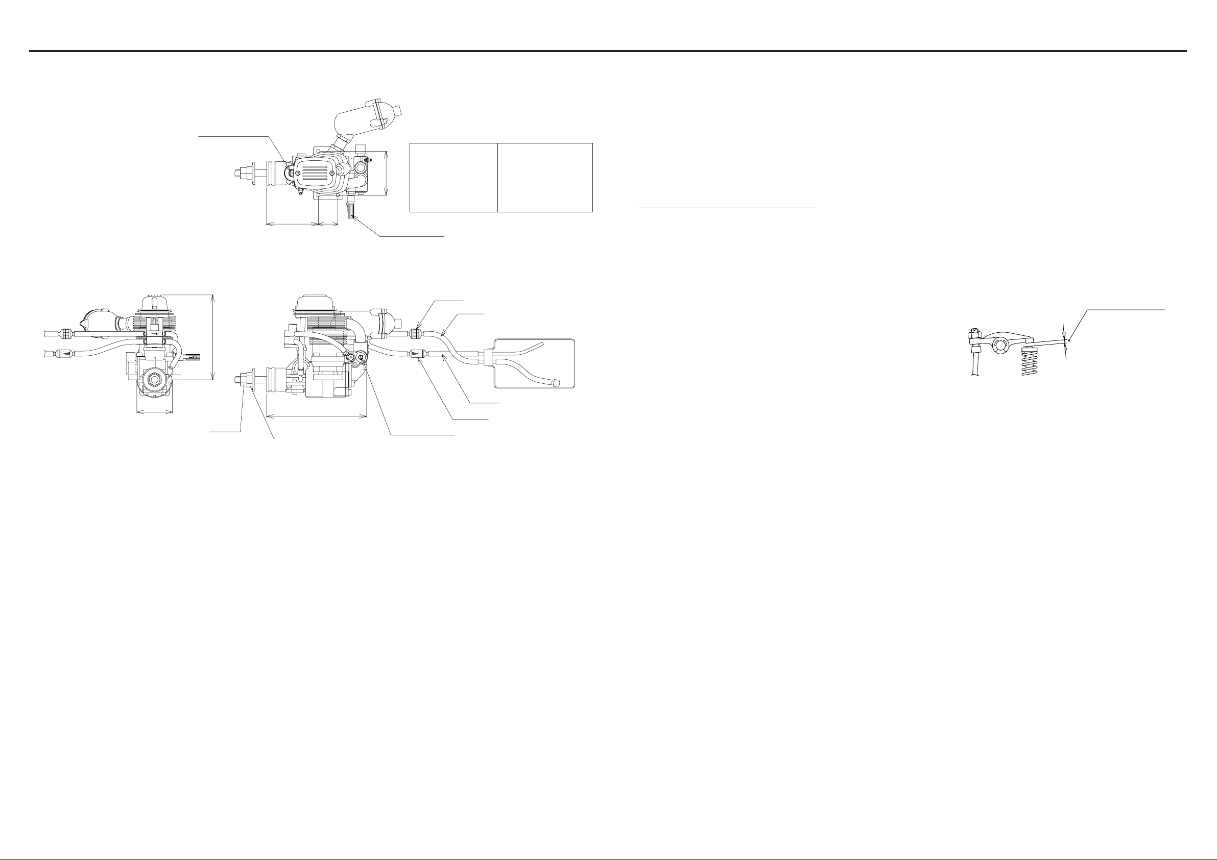
Fig.1
(
Part No. YS0064
Regulator Adjusting Screw
87
)
48
20
SPECIFICATIONS
Bore 26.2mm
Stroke 19.0mm
45
Weight (engine) 460g
(muffler) 33g
Practical rpm 2,000-15,000rpm
High Speed NeedleValve
Fuel Filter
Tube (B)
BREAK IN
To maximize engine performance and increase durability, please follow
this break-in procedure:
l. Use the same size (or slightly smaller) propeller than you intend to
use in flying.
2. Use a good quality fuel which contains 15-30% nitromethane and oil
content of 20-24%. Synthetic or castor oil can be used, or a combination
of synthetic and castor.
Do not use four cycle fuel due to low oil content.
3. The needle valve should be set so that the engine is running at a rich
setting. Run the engine approximately 20 minutes with this setting.
4. Mount the engine to the model and fly ten times with this setting.
This concludes the break-in procedure, it is advisable to always use
a slightly rich setting to keep the moving parts lubricated, even after
the break-in period .
HIGH SPEED ADJUSTMENT
1. Adjustment of high speed is done by the carburetor needle valve.When
the needle valve is turned clockwise, the mixture is leaner.When it is
turned counterclockwise, the mixture is richer. A good starting position
for the high speed needle valve is 2 1/2 turns open from the fully
closed position.
TAPPET CLEARANCE ADJUSTMENT
1. Tappet clearance is factory preset. No adjustment is necessary until
after 1 hour of operation (including break-in period).
2. Clearance adjustment should be done when the engine is cool. When
the engine temperature is high, clearance is higher due to thermal
expansion.
3. The proper clearance setting should be at 0 - 0.1mm. The adjustment
is achieved by loosening the locknut (fig.2) and turning the adjusting
screw. Tighten the locknut after the adjustment is achieved. Alter the
initial 1 hour adjustment, this procedure should be performed a few
every 2 hours of use.
Fig.2
0 - 0.1mm
35
Front Nut
97.5
FEATURES
PROPELLER INSTALLATION
The New FZ63S has set the standard by which all other 4 stroke engines
in this size category are judged.
• New regulator design for more reliable operation in high temperature
conditions.
• New cylinder desighn provides higher power and improves cooling for
longer life.
• New crankcase design is stronger to resist distortion under high horse
power loads
a double lock system for safety.
1. Mount the propeller and tighten the rear nut. Next, tighten the front
2. Select a good quality propeller that will turn in the 9,000 to 12,000
START UP
GLOW PLUG
Select the most appropriate plug from those designed specifically for
4 cycle engines. Glow plug selection greatly affects the maximum
engine output and low idle. We recommend the YS #4.
1. Remove tube B from the filter: remove tube A from the check valve,then
2. Open the needle valve 2 l/2 turns from the fully closed position.
INSTALLATION
3. Open the throttle fully and slowly turn the propeller 10 times. This
l. Connect the engine to the tank as shown in fig.1. Since high pressure
is applied to the tank, tighten all connections carefully. Care must be
taken to prevent pressure leakage due to under tightening of the check
valve or by kinking the fuel lines.
2. Always use a fuel filter. We recommend the YS fuel filter.
3. Match the direction of the check valve arrow fig.1 with the arrow facing
to wards the tank.
4. Close the throttle to the idle position and connect the glow plug battery .
DO NOT ATTEMPT TO START FULL THROTTLE,
AS THIS IS VERY DANGEROUS.
Tube (A)
Check Valve
Low Speed Needle Valve
2. When the engine is started, open the throttle gradually . Next, find the
3. For flying, it is advisable to use a slightly richer mixture setting. By
LOW SPEED ADJUSTMENT
Due to the high torque of the FZ63 engine, we have equipped it with
the mixture from low to mid throttle. This needle valve is located on the
side of the throttle barrel opposite the throttle arm (Fig.1).
nut as shown in Fig.1.
rpm range. We recommend sizes 11x7-11x9,12x6-12x8.
fill the tank. (CAUTION: If tank is filled or under pressure remove
tube A first, then tube B. Fuel will eject if tube B is removed while the
tank is pressurized. )
primes the system by pressurizing the tank and sending fuel to the
carburetor.
The engine is now ready for starting.
1. Open the low speed needle to 1 turns from fully closed position.
2. The low speed needle valve should be set after the high speed needle
3. If the engine is running rough on idle, the low speed mixture is rich.
IMPORTANT! The regulator adjusting screw on this engine is
factory set. No further adjustments are necessary. If for some reason
you have to disassemble the regulator assembly, the regulator
adjusting screw should be set flush with the regulator body.
peak position (highest RPM) by adjusting the needle valve. Then the
needle valve should be opened approximately 1/8 of a turn from full
RPM to achieve best performance. The engine may stop if the throttle
is opened to full immediately after starting. Wait until the engine
temperature rises and then open the throttle slowly .
using a richer mixture, the engine temperature is maintained and RPM
stability improves.
This engine is equipped with a new low speed needle valve to adjust
CAM GEAR TIMING ADJUSTMENT
these important steps on reassembling the cam gear.
1. Remove the carburetor and backplate assembly. Notice the impression
2. When reinstalling the cam gear, the side with a point mark should be
DIAPHRAGM AND CHECK VALVE DISASSEMBLY
Diaphragm
1. Remove the adjustment screw of the valve, and then remove the inside
valve has been adjusted. Close the throttle gradually to a idle
(approximately 2500rpm). Let it idle for 20 to 30 seconds and then
slowly advance the throttle. The adjustment is satisfactory at low speed
if transition is smooth at this time.
If the engine starts to speed up and dies on idle or starts to detonate,
when advancing the throttle, the mixture is lean. Turn the low speed
needle valve clockwise to richen and counterclockwise for a leaner
mixture (note that the direction of the low speed needle valve is
opposite the high speed needle valve). Adjustments to the low speed
needle valve should be 1/8 to 1/4 of a turn increment at a time to
achieve smooth throttle response.
2. Clean the inside with alcohol or appropriate cleaner. Reassemble.
3. Screw in the regulator screw until flush with the diaphragm body.
Check valve
1. Open the valve by rotating the body counterclockwise.
2. Reassemble the check valve carefully.
IMPORTANT! Silicone rubber is used in many parts of the YS engine.
Use only glow fuel or methanol for cleaning. Gasoline and other
volatile solutions will damage the silicone if used.
If for some reason you have to disassemble your engine, please follow
made on the crankshaft counterweight. Position it directly straight down
or in line with the case outer seam line.
facing the opening of the gear box. Note that it should also be mounted
with the point mark located towards the top of the engine just below
the cam followers.
valve and spring.
Page 2
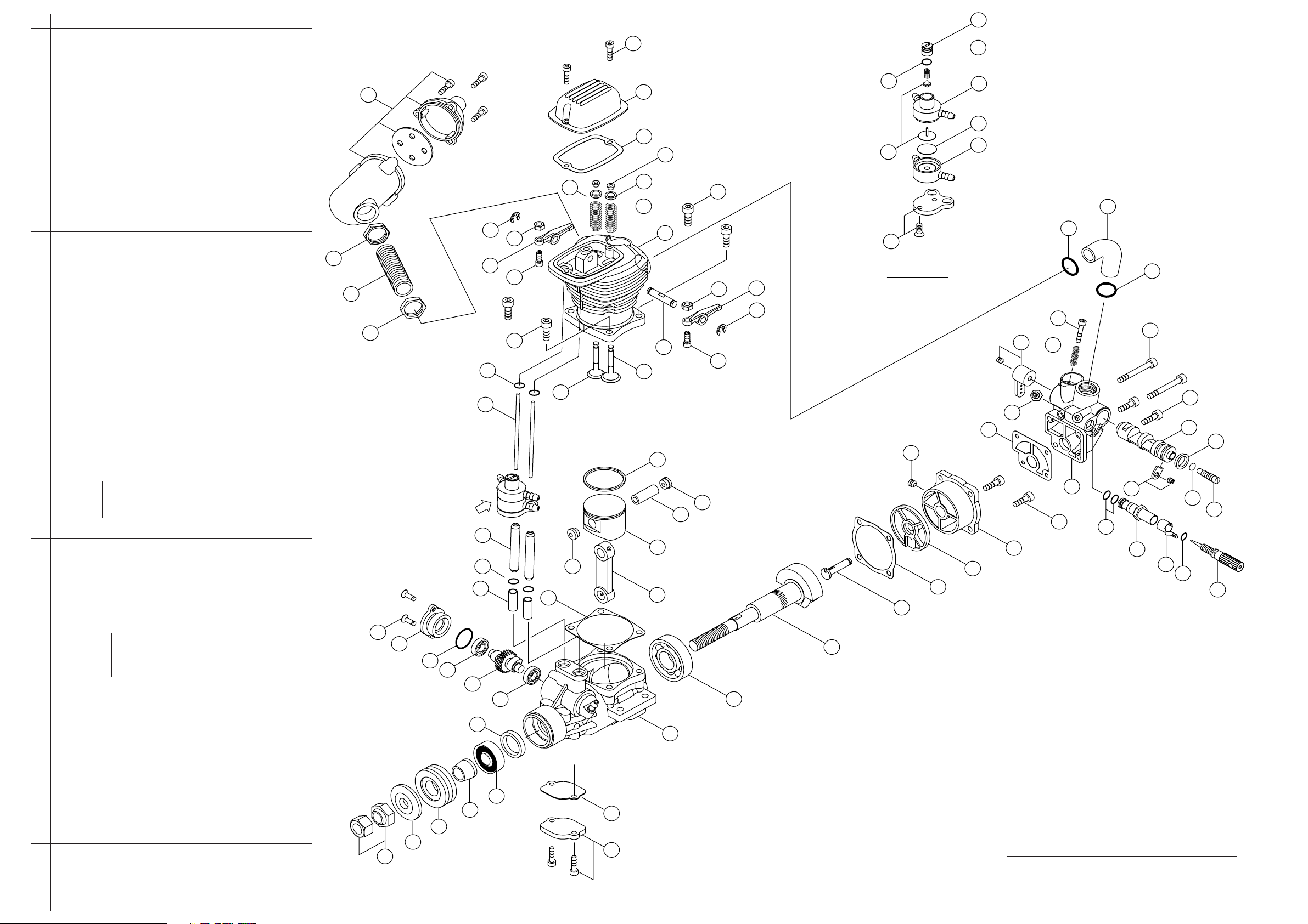
NO. PART# DESCRIPTION QTY
1 YS5000 Crankcase 1
YS5005 Cylinder head assy.
2 YS5010 Cylinder head & liner 1
3 YS2810 Intake valve 1
4 YS2815 Exhaust valve 1
5 YS2820 Valve spring set 2
6 YS2030 Spring retainer set 2
7 YS2040 Spring retainer clips 4
8 YS5015 Cylinder gasket 1
10 YS2840 Head screws 4
11 YS2845 Valve cover 1
12 YS2850 Valve cover gasket 1
13 YS2855 Valve cover screws 2
14 YS2860 Intake pipe 1
15 YS2865 Intake pipe O ring 2
16 YS4380 Crankshaft 1
17 YS2875 Rear bearing 1
18 YS2880 Front bearing 1
19 YS2885 Front bearing oil seal 1
20 YS2890 Drive washer 1
21 YS2895 Drive washer retainer 1
22 YS0825 Propeller washer 1
23 YS0830 Propeller nuts 2
24 YS5020 Piston 1
25 YS4390 Piston ring 1
26 YS4395 Wrist pin 1
27 YS2925 Wrist pin retainer 2
28 YS2930 Rocker arm set 2
29 YS0560 Tappet adjusting screws 2
30 YS0565 Tappet adjusting lock nuts 2
31 YS2935 Rocker arm shaft 1
32 YS2940 Rocker arm screw 1
33 YS0580 E ring set 2
34 YS2945 Cam gear 1
35 YS2950 Cam gear cover 1
36 YS2955 Cam gear cover O ring 1
37 YS4400 Cam gear screws 2
38 YS2960 Cam gear bearing set 2
39 YS2965 Cam follower set 2
40 YS2970 Push rods 2
41 YS2975 Push rod covers 2
42 YS2980 Push rod cover O ring set 4
43 YS2985 Con rod 1
YS4000 Back plate assy.
44 YS2990 Back plate 1
45 YS2995 Disc valve 1
46 YS3000 Disc valve pin 1
47 YS0640 Disc valve set screw 1
49 YS3005 Back plate gasket 1
50 YS3010 Back plate screws 2
YS5090 Carburetor assy.
51 YS3015 Carburetor body 1
52 YS3020 Throttle barrell 1
53 YS3025 Throttle barrell seal 1
54 YS1090 Throttle barrell retainer 1
55 YS0200 Throttle arm set 1
56 YS0785 Throttle stop screw 1
57 YS0790 Throttle stop spring 1
YS3090 Needle valve assy.
58 YS3030 Needle valve 1
59 YS2695 Needle valve O ring 1
60 YS2700 Needle socket 1
61 YS0775 Needle socket O ring set 2
62 YS2710 Needle valve detent 1
63 YS3035 Fuel nipple 1
64 YS4010 Low speed needle valve 1
65 YS4015 Low speed needle valve O ring 1
66 YS3040 Carburetor gasket 1
67 YS3045 Carburetor screws 4
YS5075 Regulator assy.
68 YS5025 Regulator adjusting screw 1
69 YS5030 Regulator adjusting screw O ring 1
70 YS5035 Plunger spring 1
71 YS5040 Plunger 1
72 YS5045 Regulator body A 1
73 YS5050 Diaphram 1
74 YS5055 Regulator body B 1
75 YS5060 Regulator bracket set 1
76 YS5065 Under cover set 1
77 YS5070 Under cover gasket 1
YS3095 Muffler set
78 YS3065 Muffler assy. 1
79 YS3070 Exhaust pipe 1
80 YS3075 Rock nuts 1
YS5080 Gasket set 4
YS5085 O ring set 11
80
79
78
80
37
23
04/03
35
22
36
20
38
A
34
21
19
41
42
39
40
42
33
28
18
38
30
29
10
68
13
70
WARRANTY
Strict quality control is implemented by our factory in all phases,
from parts manufactiring to final assembly.
If performance deteriorates or a part fails within one year of purchase
due to a manufacturing error,YS will repair or replace the engine at no
11
69
72
charge. Warranty will not cover normal wear.
Should the engine be modified, incorrectly assembled or abused,
there will be a normal charge for parts and labor. The use of four
cycle fuel due to low oil content will also void warranty.
14
15
15
56
32
12
73
7
71
74
6
10
5
2
30
28
75
DETAIL
A
33
67
55
31
57
29
3
4
67
63
66
52
53
25
27
26
24
27
8
43
47
49
45
44
50
51
54
65
64
61
60
62
59
58
46
16
17
1
77
76
YS PERFORMANCE
1295-C Industrial Court Gardnerville, NV89410
Phone: 775-782-4562 Fax: 775-783-8518
 Loading...