

Yoshitake GP-1000, GP-1010, GP-1000SS, GP-1000H, GP-1002 Installation & Operation Manual
...
■EPDT-081a■
Model GP-1000 Series
PRESSURE REDUCING VALVE
Installation & Operation Manual
Please read this bulletin thoroughly before using the pressure reducing valve, so that you may
do so correctly and safely. Please carefully store this bulletin in a handy place.
―――――――――The following safety symbols are used in this manual. ――――――――
Warning
Caution
Contents
1. Features・・・・・・・・・・・・・・・・・・・・・・・・・・・・・・・・・・・・・・・・・・・・・・・・・・・・・ 1
2. Specifications・・・・・・・・・・・・・・・・・・・・・・・・・・・・・・・・・・・・・・・・・・・・・・・・ 1
3. Dimensions and Weights・・・・・・・・・・・・・・・・・・・・・・・・・・・・・・・・・・・・・ 2
4. Operation ・・・・・・・・・・・・・・・・・・・・・・・・・・・・・・・・・・・・・・・・・・・・・・・・・・・・ 3
5. Nominal Size Selection Method
5.1 Specifications selection chart ・・・・・・・・・・・・・・・・・・・・・・・・・・・・・ 4
5.2 Safety valve setting pressure ・・・・・・・・・・・・・・・・・・・・・・・・・・・・・ 4
5.3 Characteristics chart・・・・・・・・・・・・・・・・・・・・・・・・・・・・・・・・・・・・・・ 4
5.4 Nominal size selection chart ・・・・・・・・・・・・・・・・・・・・・・・・・・・・・・ 5
5.5 Nominal size selection calculation formula ・・・・・・・・・・・・・・・・ 6
6. Installation
6.1 Example of piping ・・・・・・・・・・・・・・・・・・・・・・・・・・・・・・・・・・・・・・・・ 6
6.2 Precautions during installation ・・・・・・・・・・・・・・・・・・・・・・・・・・・・ 7
7. Operating Procedure
7.1 Precautions during operation ・・・・・・・・・・・・・・・・・・・・・・・・・・・・・ 8
7.2 Adjustment procedures ・・・・・・・・・・・・・・・・・・・・・・・・・・・・・・・・・・・ 8
8. Maintenance Procedure
8.1 Troubleshooting ・・・・・・・・・・・・・・・・・・・・・・・・・・・・・・・・・・・・・・・・・・ 9
8.2 Precautions during maintenance and inspection ・・・・・・・・・ 10
8.3 Disassembly・・・・・・・・・・・・・・・・・・・・・・・・・・・・・・・・・・・・・・・・・・・・・ 10
8.4 Precautions during reassembly ・・・・・・・・・・・・・・・・・・・・・・・・・・ 11
8.5 Exploded drawing ・・・・・・・・・・・・・・・・・・・・・・・・・・・・・・・・・・・・・・・ 12
After Sale Service
This symbol indicates a potentially hazardous situation that, if not
avoided, could result in deat h or serious injury .
This symbol indicates a hazardous situation that, if not avoided, may
result in minor or moderate injury. (“Caution” may also be used to
indicate other unsafe practices or ris ks of property damage.)
■EPDT-081a■
-1-
1. Features
GP-1000 Series pressure reducing valves for steam are pilot-operated valves which can be used with
confidence for small to large flow rate, in a host of applications ranging from building u tilities systems,
air-conditioning systems, and factory systems, etc.
2. Specifications
Model
GP-1000 GP-1010GP-1000SS GP-1000H GP-1002 GP-1012
Connection
Flanged
(JIS 10K FF)
JIS Rc Screw
Flanged
(JIS 10K FF)
Flanged
(JIS 16K FF)
Flanged
(JIS 10K FF)
JIS Rc Screw
Nominal size
15~100A 15~50A 15~100A 15~100A 15~100A 15~50A
Application Steam
Inlet pressure
0.1~1.0 MPa 0.1~1.6 MPa 0.1~0.5 MPa
0.05~0.9 MPa
0.05~0.9 MPa
0.9~1.4 MPa
0.03~0.15 MPa
Reduced pressure
90% or less of inlet pressure (gauge pressure)
Min. differential
pressure
0.05 MPa
Max. pressure
reducing ratio
20:1
Max. temperature
220℃
Valve seat leakage 0.01% or less of rated flow
Body Ductile cast iron Stainless steel Ductile cast iron
Valve Stainless steel
Valve seat Stainless steel
Piston/Cylinder Brass or Bronze Stainless steel Brass or Bronze
Material
Gasket Non asbestos
Body hydraulic test
2.0 MPa 3.2 MPa 1.0 MPa
l Stainless steel main components (piston & cylinder) are also available.(GP-1□□□S)
l All stainless steel types are also available for GP-1000.
l Adjusting handle types are also available for GP-1000 and GP-1010.(GP-1001,1011)
Caution
(1) Please collate with att ached nameplate and specification of ordered model.
※Please consult factory in case they do not match each other.
■EPDT-081a■
-2-
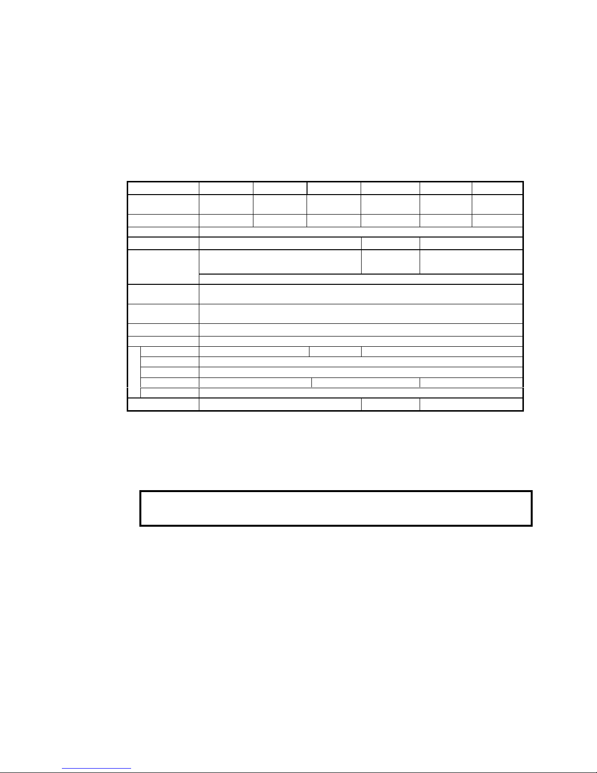
3. Dimensions and Weights
• GP‑1000,1000H,1002
(㎜)
Size
LHH
1
Weight(kg)
15A 150 285 64 8.0
20A 155 285 64 8.5
25A 160 300 67 10.0
32A 190 323 82 14.0
40A 190 323 82 14.5
50A 220 347 93 20.0
65A 245 357 100 30.0
80A 290 404 122 35.0
100A 330 450 144 52.5
• GP‑1010,1012
(㎜)
Size d
LHH
1
Weight(kg)
15A Rc 1/2 150 285 64 7.0
20A Rc 3/4 155 285 64 7.0
25A Rc 1 160 300 67 8.5
32A Rc 1-1/4 190 323 82 12.0
40A Rc 1-1/2 190 323 82 12.5
50A Rc 2 220 347 93 18.0
■EPDT-081a■
-3-
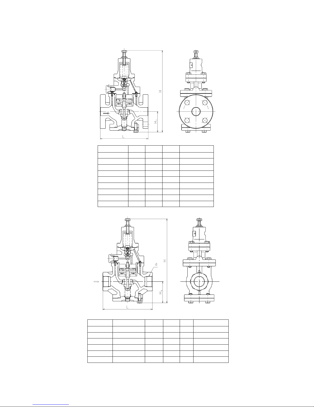
4. Operation
No. Parts name
1 Body
5 Diaphragm
8 Adjusting spring
9 Adjusting screw
11 Main valve
12 Main valve seat
13 Main valve spring
14 Piston
15 Cylinder
19 Pilot valve
20 Pilot valve seat
28 Strainer
42 Inlet press. passage
43 Reduced press. Sensing port
44 Diaphragm chamber
The pressure-reducing valve reduces pressure by the throttling the valve. The valve is composed of the
main valve and main valve seat for throttling, and adjusting spring, diaphragm, pilot valve, and piston
for pressure sensing and activation.
(1) When the pressure-reducing valve is mounted correctly, releasing the compression of adjusting
spring [8] allows the spring to close main valve [11] and pilot valve [19]. Slowly open the gate valve
and allow the high-pressure fluid to flow in. Inlet pressure is applied to the downside of the main
valve. High-pressure fluid passes through strainer [28] via inlet pressure passage [42] to also apply
inlet pressure to the downside of the pilot valve.
(2) Turing adjusting screw [9] clockwise compresses the spring, which flexes diaphragm [5] to open the
pilot valve.
(3) Inlet pressure via inlet pressure passage and pilot valve enters the upside of the piston. The pressure
overrides the pressure on the downside of the main valve and the load of main valve spring[13], to
open the main valve. The fluid then begins to flow from the inlet side.
(4) Reduced pressure is led to diaphragm chamber [44] via reduced pressure sensing port [43]. The
diaphragm receives the reduced pressure to be balanced with the adjusting spring load, and control
the pilot valve travel.
(5) The change of pilot valve travel changes the flow rate of fluid to the upside of the piston, and
controls the main valve travel to obtain appropriate reduced pressure.
 Loading...