

Yorkville Sound YS1036 User Manual
O w n e r ’ s M a n u a l
Manual-Owners-YCS100-00-1v2.pdf
G u i d e d e l ’ u t i l i s a t e u r
Traynor Custom Special 100
A l l - T u b e G u i T A r A m p l i f i e r
MODEL TYPE: YS1036
IMPORTANT SAFETY INSTRUCTIONS
safety-4v3.eps • Oct. 26/05
CAUTION:
TO REDUCE THE RISK OF ELECTRIC SHOCK, DO
NOT REMOVE COVER (OR BACK).
NO USER SERVICEABLE PARTS INSIDE.
REFER SERVICING TO QUALIFIED
SERVICE PERSONNEL.
INSTRUCTIONS PERTAINING TO A
RISK OF FIRE, ELECTRIC SHOCK,
OR INJURY TO PERSONS
Read Instructions
The Owner’s Manualshould be read and understood
before operation of your unit. Please, save these instructions for future reference.
Packaging
Keep the box and packaging materials, in case the unit
needs to be returned for service.
Warning
When using electric products, basic precautions should
always be followed, including the following:
Power Sources
Your unit should be connected to a power source only of the voltage
specified in the owners manual or as marked on the unit. This unit has a
polarized plug. Do not use with an extension cord or receptacle unless
the plug can be fully inserted. Precautions should be taken so that the
grounding scheme on the unit is not defeated.
Hazards
Do not place this product on an unstable cart, stand, tripod, bracket or
table. The product may fall, causing serious personal injury and serious
damage to the product. Use only with cart, stand, tripod, bracket, or
table recommended by the manufacturer or sold with the product.
Follow the manufacturer’s instructions when installing the product and
use mounting accessories recommended by the manufacturer.
The apparatus should not be exposed to dripping or splashing water;
no objects filled with liquids should be placed on the apparatus.
Terminals marked with the “lightning bolt” are hazardous live; the
external wiring connected to these terminals require installation by an
instructed person or the use of ready made leads or cords.
Ensure that proper ventilation is provided around the appliance.
No naked flame sources, such as lighted candles, should be
placed on the apparatus.
Power Cord
The AC supply cord should be routed so that it is unlikely that it will be
damaged. If the AC supply cord is damaged DO NOT OPERATE THE UNIT.
Service
The unit should be serviced only by qualified service personnel.
AVIS:
AFIN DE REDUIRE LES RISQUE DE CHOC ELECTRIQUE,
N’ENLEVEZ PAS LE COUVERT (OU LE PANNEAU ARRIERE)
NE CONTIENT AUCUNE PIECE
REPARABLE PAR L’UTILISATEUR.
CONSULTEZ UN TECHNICIEN QUALIFIE
POUR L’ENTRETIENT
INSTRUCTIONS RELATIVES AU RISQUE
DE FEU, CHOC ÉLECTRIQUE, OU
BLESSURES AUX PERSONNES
Veuillez Lire le Manuel
Il contient des informations qui devraient êtres comprises
avant l’opération de votre appareil. Conservez S.V.P. ces
instructions pour consultations ultérieures.
Emballage
Conservez la boite au cas ou l’appareil devait être
retourner pour réparation.
Attention:
Lors de l’utilisation de produits électrique, assurezvous d’adhérer à des précautions de bases incluant
celle qui suivent:
Alimentation
L’appareil ne doit être branché qu’à une source d’alimentation
correspondant au voltage spécifié dans le manuel ou tel qu’indiqué sur
l’appareil. Cet appareil est équipé d’une prise d’alimentation polarisée.
Ne pas utiliser cet appareil avec un cordon de raccordement à moins
qu’il soit possible d’insérer complètement les trois lames. Des
précautions doivent êtres prises afin d’eviter que le système de mise à
la terre de l’appareil ne soit désengagé.
Risque
Ne pas placer cet appareil sur un chariot, un support, un trépied ou une
table instables. L’appareil pourrait tomber et blesser quelqu’un ou subir
des dommages importants. Utiliser seulement un chariot, un support,
un trépied ou une table recommandés par le fabricant ou vendus avec
le produit. Suivre les instructions du fabricant pour installer l’appareil et
utiliser les accessoires recommandés par le fabricant.
Il convient de ne pas placer sur l’appareil de sources de flammes
nues, telles que des bougies allumées.
L’appeil ne doit pas être exposé à des égouttements d’eau ou des
éclaboussures et qu’aucun objet rempli de liquide tel que des vases
ne doit être placé sur l’appareil.
Assurez que lappareil est fourni de la propre ventilation.
Les dispositifs marqués d’une symbole “d’éclair” sont des parties
dangereuses au toucher et que les câblages extérieurs connectés à
ces dispositifs de connection extérieure doivent être effectivés par un
opérateur formé ou en utilisant des cordons déjà préparés.
Cordon d’Alimentation
Évitez d’endommager le cordon d’alimentation. N’UTILISEZ PAS
L’APPAREIL si le cordon d’alimentation est endommagé.
Service
Consultez un technicien qualifié pour l’entretien de votre appareil.

The Traynor YCS100
•
Q
U
A
L
I
T
Y
&
I
N
N
O
V
A
T
I
O
N
•
•
E
S
T
A
B
L
I
S
H
E
D
1
9
6
3
•
Introduction
Thank you for purchasing a new Traynor Custom Special 100 guitar amplifier head. It represents a blend of the
latest technology providing great flexibility and featuring vintage tube circuitry for an ultimate tone and trouble free
performance for years to come.
Designed by musicians, for musicians, Traynor Custom Special amplifiers are built for maximum versatility but are
still simple to operate. It's always easy to get a great tone from a Traynor amp. With the Custom Special series, we
made it even easier by adding an array of tone sculpting options like Scoop, Bright and Modern voicing switches,
Resonance and Presence controls; and yes, with the addition of a Solo Boost knob, these amps actually go to 11.
For greater flexibility, the YCS100 output stage can be operated in either 100-watt or 30-watt modes. The YCS100
will operate in 100-watt (Class AB) mode that will produce a full 100-watts of output power, used where maximum
headroom is needed. For situations where more tube warmth is required at lower volume levels, the YCS100 can be
switched to 30-watt (Class A) mode. This is achieved by cutting the operating voltage to the output tubes in half and
automatically adjusting the bias level to operate in Class A mode.
Please take a few moments to read this manual in order to gain maximum enjoyment from your new YCS100.
Features
• 100% Designed and Manufactured in North America.
• All-tube design with four EL34EH and four 12AX7A Premium tubes.
• All plywood cabinet construction guarantees the durability and rigidity that made Traynor
famous.
• All three channels have separate tone controls for flexibility (lead1, lead 2 and clean 3).
• Classic Long-S tyle Accutronic s® Reverb, wi th dual sprin gs, for
authentic vint age sound.
• Dual speaker jacks and impedance selector for added versatility.
• Traynor TFS-4 custom footswitch, with 20-foot cable included.
• DC powered filament supply on pre-amp tubes ensures reduced
hum.
• 100-watt Class AB output as well as 30-watt Class A output capability.
• Fully regulated power supply ensures ultra low noise.
• The best warranty in the business: a 2-year unlimited, transferable
* “Even if you break it” warranty (valid in the USA and Canada only).
1

Chassis Layout
1
2
3
4
5
6
7
8
9
10
11
12
13
14
15
16
17
18
19
20
2738913151819
145610111214161720
Front
Input Jack – ¼-inch phone jack.
Channel 1-2-3 Indicator LED – Illuminates when active.
Channel Select Switches – Channel 1 and 2 are optimized for overdrive sounds, Channel 3 for clean.
Channel 1-2-3 Gain and Volume Controls.
Channel 1-2-3 Boost Switch – Kicks in an extra stage of gain
Channel 1-2-3 Boost LED – Illuminated Red when the boost is active.
Channel 1-2-3 Tone Controls – Treble, Bass, & Middle.
Channel 1-2-3 Modern Switches – Shifts the tone control range from a Vintage to a Modern sound.
Channel 1-2 Scoop Switches – Ad ds midrange d ip as well as bass and treble boost for
a more “chun ky” sound.
Channel 3 Bright Switch – Add sparkle to your clean sound.
Channel 1-2-3 Reverb Controls – Controls the amount of reverb return for each individual channel.
Channel 1-2-3 Effects Controls – Controls the amount of effect return for each individual channel.
Presence Control – Controls the amount of high frequency “Presence” in all three channels.
Resonance Control – Controls the low frequency “damping” of the amplifier and will add more
rumble to the bottom end of all three channels.
Solo Boost – Dial in the amount of extra volume you want for solos. This control is activated by the
footswitch controller or by the front panel switch (if the foot controller is not plugged in).
Master Volume – This Control adjusts the overall volume of all three channels.
Tuner Mute – Mutes the output from the amplifier as well as the D.I. and headphone outputs.
Power Indicator Jewel – Illuminates red when in Active mode, and yellow when in Standby mode.
Standby Switch – Activates standby mode to keep the tubes warm while the amp is not in use.
This switch operates only on the power tubes so the pre-amp tubes remain active. The amplifier
can be used as a pre-amp for recording or for silent practicing with headphones. The speakers do
not need to be plugged in for operation in standby mode.
Power Switch – Turns the AC mains on and off.
2
Chassis Layout
21
22
23
24
25
26
27
28
29
•
Q
U
A
L
I
T
Y
&
I
N
N
O
V
A
T
I
O
N
•
•
E
S
T
A
B
L
I
S
H
E
D
1
9
6
3
•
21
2223242526
282927
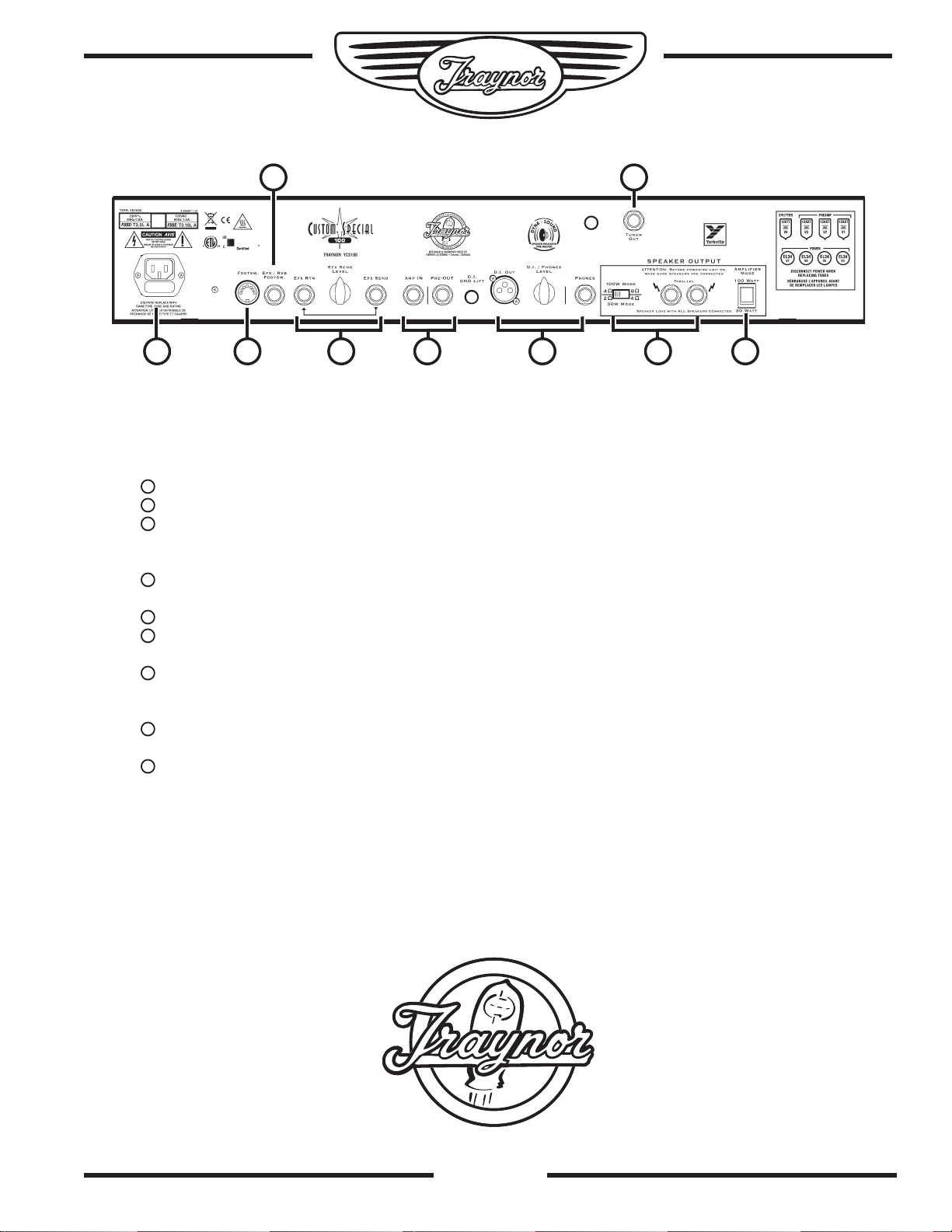
Rear
Fuse and Power Cord – Make sure to replace fuse with same type and rating.
Footswitch Jack – The footswitch cable plugs in here. Uses a standard MIDI/sync cable.
EFX / RVB Footswitch Jack – A ¼-inch TRS input that connects to a standard dual latching
footswitch such as the Traynor TFS-2. The reverb or the effects in all three channels can be
defeated via this footswitch.
Send / Rtn Jacks – ¼-inch phone Input and Output jacks with controllable effects send. The return
is controlled by the individual channel returns on the front panel.
Amp In / Pre Out Jacks – Can be used as a loop-thru for connecting pedals.
D.I. / Headphone Outputs – Outputs with simulated speaker compensation. They can be used for
recording or for silent practicing. They remain active when the amplifier is in standby mode.
Speaker Outputs / Impedance Selector – Connect your speakers here. Make sure that your
speakers are properly connected before operating the amplifier and that the impedance selector is
set to the proper position for matching up to the speakers.
Amplifier Mode Switch – The YCS100 can be operated in either 100-watt Class AB mode or in
30-watt Class A mode.
Tuner Out – This jack provides a buffered output from the guitar and remains active when the tuner
mute switch on the front panel is depressed.
3

Channel 1
5
8
11
12
13
14
15
17
24
•
Q
U
A
L
I
T
Y
&
I
N
N
O
V
A
T
I
O
N
•
•
E
S
T
A
B
L
I
S
H
E
D
1
9
6
3
•
Channel 1 is the lead/overdrive channel and is
selected in one of two ways, via the Channel Select
switch on the control panel, or via the Channel 1
Select button on the supplied footswitch pedal. The
red LED, located next to the Channel 1 Select Switch
illuminates when Channel 1 is active.
Gain & Volume Controls 4
Channel 1 uses a Gain control in conjunction with a
Volume control to control the amount of tube-based
overdrive and volume. The Gain control is used to
adjust the amount of overdrive, while the Volume control
allows you to set the actual volume of the channel.
Channel 3
Channel 3 is the clean channel; it has one less gain
stage available. All of the functions remain the same
as Channels 1 and 2 with the exception that the Scoop
function has been replaced with a Bright switch to add
more sparkle to your clean sound. By incorporating the
Boost switch, Channel 3 can also give you a variety of
overdrive sounds as well.
Master Controls
Presence Control
The Presence Control shapes the overall brightness of
all three channels.
Boost Switch
A boost circuit is provided to help achieve more
overdrive for leads. The boost can be selected via the
front panel switch. A red LED illuminates to indicate
when the boost is active.
Channel 1 Tone Controls 7
The Treble, Bass, and Middle tone controls help shape
your sound. These controls are post-gain and prevolume and are active only when Channel 1 is selected.
Modern Switch
The Modern switch controls the frequency range that
the tone controls work in. You can choose from a more
vintage sound with emphasis on the midrange or a
slightly deeper modern sound. The green LED above
the switch indicates that you are in modern mode.
Scoop Switch 9
The Scoop provides deep midrange cut with a bass
boost to get that deep, chunky sound. A yellow LED
indicates when you are in the Scoop mode.
Reverb Return
The Reverb Return controls the amount of reverb return
from the internal Accutronics® spring reverb tank. This
control is active only when Channel 1 is active.
Effects Return
This controls the amount of return signal from the
external effect plugged into the rear panel EFX RTN jack.
This control is active only when Channel 1 is active.
Channel 2
All of the functions of Channel 2 are
identical to Channel 1 with the exception
that there is slightly more bass dialed in
so that Channel 2 will sound a bit fatter
at lower gain settings, making it better
suited for crunch sounds.
Resonance Control
The Resonance Control adjusts the damping factor of
the speakers in the bass frequencies, helping loosen
or tighten the bottom end. Turning the Resonance
control up (clockwise) adds more rumble, turning it
down (counter-clockwise) tightens up the bottom end.
Solo Control
The Solo Control adjusts the amount of extra volume you
can kick in via the footswitch or the panel mounted control.
Master Volume 16
The Master Volume control adjusts the overall level of
all three channels.
Tuner Mute
The Tuner Mute switch cuts the amplifier, D.I. and
headphone outputs. The Tuner Out jack will remain
active for silent tuning of your guitar.
Standby Switch & Indicator 18 19
The Standby switch controls the high-voltage power being
supplied to the output tubes only. Standby mode keeps
the tubes warmed up when the amp is not in use. The
large, jewel indicator on the front panel glows red when the
amp is fully powered-up and changes to yellow when the
high voltage circuit has been turned off (when in Standby
mode). Putting the amp into Standby mode (i.e. during set
breaks) shuts off the amplifier output stage and effectively
increases tube life by reducing wear on the tubes.
The pre-amp tubes remain active so that the D.I. and
headphone outputs can be used for silent practice or for
recording. You do not need to connect speakers to
the amplifier when operating in standby mode.
EFX Send Jack, Return Jack & Send Level 23
The Send and Return jacks of the YCS100
allow convenient use of external effect units.
Simply connect a ¼-inch phone cable to the
Send jack of the YCS100 and then connect
4

this cable to the Input of your effects unit. To send the
25
22
23
27
28
•
Q
U
A
L
I
T
Y
&
I
N
N
O
V
A
T
I
O
N
•
•
E
S
T
A
B
L
I
S
H
E
D
1
9
6
3
•
processed signal back to the YCS100, connect the
output of the effects unit to the Rtn jack of the YCS100.
The Send Level control enables fine adjustment of the
signal being sent to the external effects unit. The front
panel mounted EFX Return controls will allow you to
adjust the amount of effect return to each individual
channel. As an example you can set up a very lush
chorus sound in Channel 3 yet still have a dry chunky
sound set up in Channel 2 without having to do a
pedal dance. Simply switch back and forth between the
channels and the sound will already be there.
Amp In & Pre-amp Out
The Amp In and Pre-Amp Out jacks can be used as
a loop-thru for guitar pedals or other effect devices.
Simply plug a ¼-inch cable from the Pre-Amp Out jack
of the YCS100 to the input of the effect unit or pedal.
Plug another ¼-inch cable from the output of the effect
unit, or pedal, to the Amp In jack of the YCS100. This
is handy when you have devices that are intended for
insertion into the signal chain. The signal level at this
point is -10dBV so it will work with most guitar effect
pedals as well as professional rack equipment.
DIN Footswitch Jack*
The DIN footswitch jack on the rear of the YCS100 is
intended to connect with the Traynor TFS-4 footswitch
pedal via a standard MIDI/sync cable. This will allow
the user to access the three individual channels and
the Solo volume boost function via the foot-controller.
With the TFS-4 connected, the channel selection can
still be achieved via the front panel switches; the Solo
function will be overridden by the foot-controller.
¼ -inch Footswitch Jack*
Connecting a latching dual footswitch, such as the
Traynor TFS-2, to the ¼-inch TRS Footswitch jack will
allow separate defeating of the Reverb and Effects
return signals. This will defeat the return signals in all
three channels at once. LED’s will indicate the status
mounted on the TFS-2.
*The switching is accomplished with internal relays so
there are no audio signals flowing through the footswitch
cables. Footswitch-induced noise is never an issue. The
YCS100 ¼-inch footswitch is compatible with most aftermarket latching dual footswitch pedals.
Speaker Jacks and Impedance Selector Switch
The dual ¼-inch jacks allow convenient
connection of external speaker cabinets.
Insure that speakers are properly
connected and that the impedance
selector is set to the appropriate position
before operating the amplifier.
Phones/Line Out, XLR Balanced Line Out Jacks
and Level Control 27
For maximum versatility, The YCS100 has both ¼-inch
and XLR Line Outs. The ¼-inch output also doubles as a
headphone jack. This Phones/Line Out jack can be used
with any stereo headphone. The signals sent from these
outputs are post-master and have speaker simulator
compensation. These outputs will remain active when the
amplifier is in standby mode so the YCS100 can be used
as a pre-amp for recording or simply for silent practicing.
When operating in standby mode, speakers do not need
to be connected. If you are using the XLR line out as an
output to a mixing console for live sound reinforcement
the Tuner Mute will also mute these outputs.
Amplifier Mode
The YCS100 output stage can be operated in either
100-watt or 30-watt modes. While in 100-watt (Class
AB) mode. The amp will produce a full 100-watts of
output power; this is for situations where maximum
headroom is required. For situations where more tube
warmth is required at lower volume levels, the YCS100
can be switched to operate in 30-watt (Class A mode).
This is done by cutting the operating voltage to the
output tubes in half and automatically adjusting the bias
level to operate in Class A mode. All four output tubes
still operate in the 30-watt mode but at a reduced power
level, therefore increasing output tube longevity.
The output impedance of the YCS100 power
amplifier changes in different power modes
therefore the MINIMUM speaker load impedance
also changes. In 30-Watt mode, you can choose
between a MINIMUM load impedance of 2-ohms or
4-ohms. When in 100-Watt mode, the MINIMUM load
impedance choices are 4-ohms or 8-ohms.
Tech Note: Knowing the MINIMUM load impedance of an
amplifier is important when connecting speaker cabinets to
the amplifier. Each speaker cabinet has a rated NOMINAL
impedance that directly affects the sound and performance
of the power amplifier. If you use speakers that load the
amplifier too much (i.e. using a 2-ohm load on an amplifier
rated at 8-ohms), you will make the amplifier exceed it’s
capability and will lead to shorter tube life.
Speaker Cabinets
You can either connect speakers in parallel or series.
Most speaker enclosures have parallel output jacks that
enable users to chain speaker extension cabinets
together. Series connections are rarely used.
The easiest way to describe this is if
you have two 8-ohms speaker cabinets
connected in parallel the resulting
impedance would be 4-ohms (16-ohms if
they were wired in series).
5
 Loading...