

Yorkville Sound YS1031 User Manual
P O W E R E D L O U D S P E A K E R S Y S T E M
éXcursion 2000
OWNER'S MANUAL
MANUEL DE'UTILISATEUR
Yorkville
TYPE: YS1031
Manual-Owners-EX2-1v6.pdf

IMPORTANT SAFETY INSTRUCTIONS
INSTRUCTIONS PERTAINING TO A
RISK OF FIRE, ELECTRIC SHOCK,
OR INJURY TO PERSONS
CAUTION:
TO REDUCE THE RISK OF ELECTRIC SHOCK, DO
NOT REMOVE COVER (OR BACK).
NO USER SERVICEABLE PARTS INSIDE.
REFER SERVICING TO QUALIFIED
SERVICE PERSONNEL.
Read Instructions
The Owner’s Manualshould be read and understood
before operation of your unit. Please, save these instructions for future reference.
Packaging
Keep the box and packaging materials, in case the unit
needs to be returned for service.
Warning
When using electric products, basic precautions should
always be followed, including the following:
Power Sources
Your unit should be connected to a power source only of the voltage
specified in the owners manual or as marked on the unit. This unit has
a polarized plug. Do not use with an extension cord or receptacle
unless the plug can be fully inserted. Precautions should be taken so
that the grounding scheme on the unit is not defeated.
Hazards
Do not place this product on an unstable cart, stand, tripod, bracket or
table. The product may fall, causing serious personal injury and serious
damage to the product. Use only with cart, stand, tripod, bracket, or
table recommended by the manufacturer or sold with the product.
Follow the manufacturer’s instructions when installing the product and
use mounting accessories recommended by the manufacturer.
The apparatus should not be exposed to dr
no objects filled with liquids should be placed on the apparatus.
rminals marked with the “lightning bolt” are hazardous live; the
Te
external wiring connected to these terminals require installation by an
instructed person or the use of ready made leads or cords.
No naked flame sources, such as lighted candles, should be
placed on the apparatus
.
Power Cord
The AC supply cord should be routed so that it is unlikely that it will be
damaged. If the AC supply cord is damaged DO NOT OPERATE THE UNIT.
Service
The unit should be serviced only by qualified service personnel.
ipping or splashing water;
INSTRUCTIONS RELATIVES AU RISQUE
DE FEU, CHOC ÉLECTRIQUE, OU
BLESSURES AUX PERSONNES
AVIS:
AFIN DE REDUIRE LES RISQUE DE CHOC ELECTRIQUE,
N’ENLEVEZ PAS LE COUVERT (OU LE P
NE CONTIENT AUCUNE PIECE
REPARABLE PAR L’UTILISATEUR.
CONSULTEZ UN TECHNICIEN QUALIFIE
POUR L’ENTRETIENT
Veuillez Lire le Manuel
Il contient des informations qui devraient êtres comprises
l’opération de votre appareil. Conservez S.V.P. ces
avant
instructions pour consultations ul
Emballage
Conservez la boite au cas ou l’appareil devait être
retourner pour
réparation.
Attention:
Lors de l’utilisation de produits électrique, assurez-vous
d’adhérer à des précautions de bases incluant celle qui
suivent:
Alimentation
L’appareil ne doit être branché qu’à une source d’alimentation
correspondant au voltage sp
l’appareil. Cet appareil est équipé d’une prise d’alimentation polarisée.
Ne pas utiliser cet appareil avec un cordon de raccordement
qu’il soit possible d’insérer complètement les trois lames. Des
précautions doivent êtres prises afin d’eviter que le système de mise à
la terre de
l’appareil ne soit désengagé.
Risque
Ne pas placer cet appareil sur un chariot, un support, un trépied ou une
table instables.
des dommages importants. Utiliser seulement un chariot, un support,
un tr
épied ou une table recommandés par le fabricant ou vendus avec
le produit. Suivre les instructions du fabricant pour installer l’appareil et
utiliser les accessoires recommand
Il convient de ne pas placer sur
nues, telles que des bougies allumées.
L’appeil ne doit pas être exposé à des égouttements d’eau ou des
éclaboussures et qu’aucun objet rempli de liquide tel que des vases
ne doit
Les dispositifs marqu
dangereuses au toucher et que les
ces dispositifs de connection ex
opérateur formé ou en utilisant des cordons déjà préparés.
L’appareil pourrait tomber et blesser quelqu’un ou subir
être placé sur l’appareil.
Cordon d’Alimentation
Évitez d’endommager le cordon d’alimentation. N’UTILISEZ PAS
L’APPAREIL si le cordon d’alimentation est endommagé.
Service
Consultez un technicien qualifié pour l’entretien de votre appareil.
écifié dans le manuel ou tel qu’indiqué sur
és par le fabricant.
l’appareil de sources de flammes
és d’une symbole “d’éclair” sont des parties
câblages extérieurs connectés à
térieure doivent être effectivés par un
ANNEAU ARRIERE)
térieures.
à moins
safety-4v2.eps Aug 26/05

Introduction
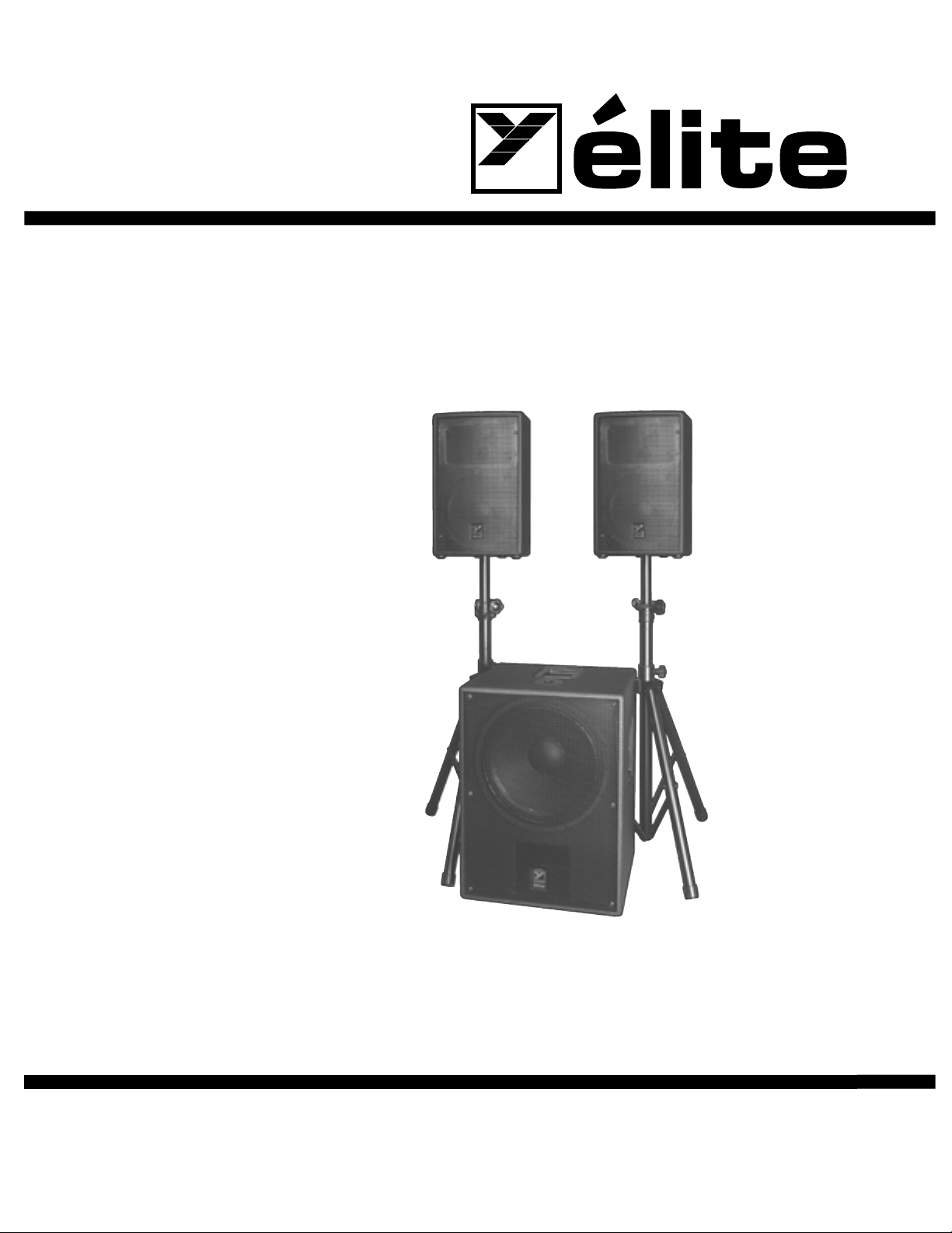
P O W E R E D L O U D S P E A K E R S Y S T E M
The Yorkville éXcursion 2000 is the ultimate all-inone complete PA system for live sound or mobile DJ
applications. The system includes one 18-inch high
efficiency subwoofer and two specially optimized
satellite speaker enclosures. The éXcursion 2000’s
active crossover network and three amplifiers are
conveniently housed in the subwoofer enclosure. The
Class D and two 3-tier Class A/B amplifiers ensure ultra
quiet operation, low distortion and a high SPL output.
This is not a system that’s been hastily put together; the
éXcursion 2000 was designed as a complete solution.
The system assembles into an integrated package
to make it easier for transportation and storage. The
éXcursion 2000 was designed for the road.
The éXcursion 2000 can be used as a single
system (subwoofer with two satellites) or as a dual
system using two éXcursion 2000 systems. When
the éXcursion 2000 is used in a dual system
configuration, each system behaves as individual
channels. The dual-system configuration allows the
use of the two satellite speakers on each side of the
stage that can be positioned for greater dispersion. The
éXcursion 2000 subwoofer has a pole-mount adapter
built-in to eliminate the necessity of using two speaker
stands. See your Yorkville dealer for information on the
variety of poles and stands available.
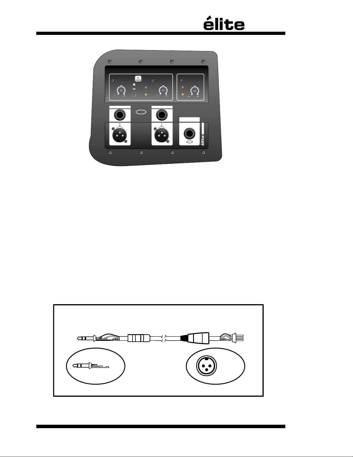
1. Input Jacks
i. Left & Right Input Jacks
The input jacks of the éXcursion 2000 are
designed for operation with line-level signals.
The XLR and balanced ¼-inch TRS jacks are
wired in parallel, functionally identical except for
the style of connector.
Note: The required input level for full power
operation, when the Level controls are set to
the center detent position, is approximately +4
dBv (1.2 volts). Increasing this setting allows
the éXcursion 2000 to be driven with sources
that have a low signal level.Connecting signals
to both types of inputs on any one channel
(XLR and ¼-inch) is not recommended.
ii. Aux Bal Subwoofer In Jack
This balanced input allows the subwoofer to be
fed from a separate signal source, other than the
signals being fed to the Left and Right amplifiers.
This feature allows the subwoofer to be mixed
separately from the Left and Right signals.
iii. Mono/Stereo Switch
In Stereo mode, the éXcursion 2000 routes the
two signals from the left and right inputs to the
corresponding satellite enclosures. If an individual
signal is sent to the éXcursion 2000, in either the
left or right channel, enabling the Mono mode will
route the signal to both satellite enclosures. If a
stereo signal is used, both the left and right will
be summed when the Mono mode is selected.
Note: Mono operation (using a single source)
will require setting the applicable level control
at a higher level.
2. Level Controls
i. Left & Right Level Controls
The Left and Right Level controls adjust
the output level of the corresponding satellite
enclosures. Adjustments can be made to alter
the balance of the satellites, compensate for
signal sources that are not the standard +4 dBv
line level or to tweak the SPL levels appropriate
to the application. The Left Level and Right
Level are normally set to the center detent.
1
ii. Subwoofer
CLIP SUB C LIP
LIMIT SUB L IMIT
LEFT
LEVEL
12
dB
RIGHT
LEVEL
12
dB
SUBWOO FER
LEVEL
12
dB
STEREO
MONO
00
0000
BAL
PARALLEL INPU TS
PARALLEL INPU TS
LEF T RIG HT
I N P U T S
BAL
LEF T RIG HT
AUX B AL
SUBW OOFE R I N
1/4-inch T.R.S.
Phone Plug
Balanced 1/4-inch T.R.S. to Balanced XLR
XLR Plug
(Male)
Tip = 0°
Ring = 180°
Sleeve = Ground
1
Pin 1 = Ground
Pin 2 = 0°
Pin 3 = 180°
2
3
Level Control
The Subwoofer
Level control allows
fine-tuning of the
low frequency
output. Adjustments
can be made to
compensate for
signal sources that
are not the standard
+4 dBv level.
3. Clip Indicators
i. Clip Indicator LEDs
The Clip Indicator
LED shows when there is ex-cessive input level on
either the Left or Right Inputs.
ii. Sub Clip Indicator LED
The Sub Clip Indicator LED indicates excessive
levels for signals going to the subwoofer
amplifier. Indications of excessive levels are
monitored either from the signals being sent from
the Left and Right Inputs or from the Aux Bal
Subwoofer In jack.
4. Protection
The éXcursion 2000 uses a sophisticated, multi-
stage limiting system that prevents clipping of the
amplifiers while accommodating a wide range of
input levels. The limiter circuitry protects the entire
system against most instances of overpowering.
Note: Continuous acoustic feedback may cause
damage to the light bulbs (CTL™ horn protection
circuitry) or to the speakers in the satellites.
i. Limit Indicator LED
The Limit Indicator
LED indicates
when the maximum
operating level for
the satellites has
been reached.
When the LED is
illuminated, the
circuitry is actively
limiting the output.
Increasing the
input signal level
or turning up the
Level controls will
not increase the
operating level
beyond the limit
indicated. When the unit is driven into limiting, the
internal Limiter circuit becomes triggered and will
reduce the gain. This will not significantly degrade
the sound quality.
Note: Operating a few dB into limiting will
ensure that the system is operating at its
maximum output. Operating excessively into
limiting will make the system more susceptible
to feedback.
ii. Sub Limit Indicator LED
The Sub Limit Indicator LED illuminates when
the maximum recommended operating-level of
the subwoofer has been reached. Increasing the
input signal level or turning up the Level controls
will not increase the operating level beyond
the limit indicated. When the internal Limiter
circuit becomes active the sound quality will not
significantly be degraded.
2
YS# 8489 - Split Lock-Washer
YS
# 8936 - Bolts
YS
# 8817 - Washer
YS
# 8440 - Velcro™ Strap
YS
# 8577 -
Swivel Caster
The éXcursion 2000 System
The Yorkville éXcursion 2000 system is shipped in two cartons. The main carton contains
the éXcursion 2000 main unit (subwoofer w/amplification) and the Dolly. The hold-down
strap is used to secure the dolly and the sub together for shipping. The second carton
contains the 2 éXcursion 2000 satellites, 4 metal casters, the power cord and these
operating instructions.
Carton 1
• éXcursion 2000 main unit (subwoofer w/amplification)
• Transportation Dolly
• Power Cord
• Operating instructions
Carton 2
• 2 éXcursion 2000 satellite speaker cabinets
• 4 Swivel Casters (YS#8577)
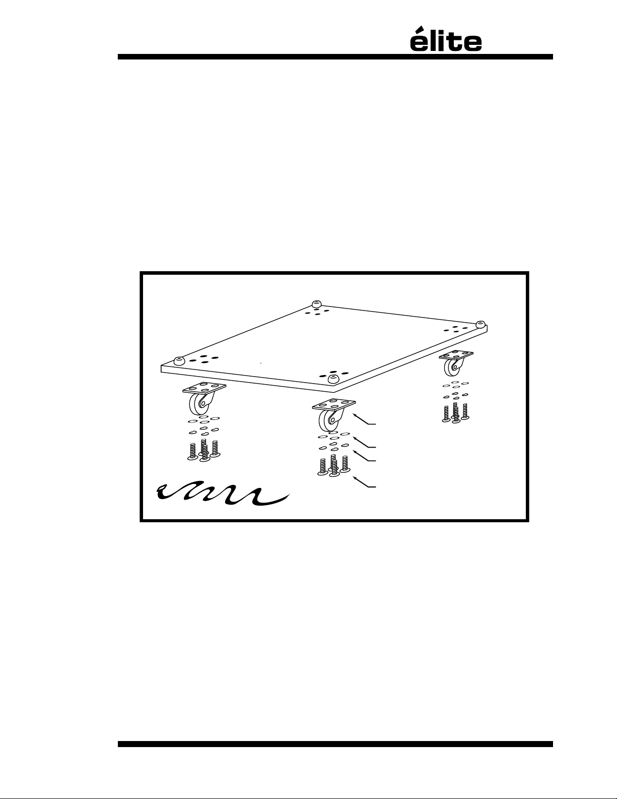
Some assembly required.
The bolts provided to attach the casters on the dolly have been conveniently screwed into the dolly.
This allows you to find the mounting holes and prevents the bolts from being lost in shipping.
When installing Swivel Casters follow the sequence shown in the assembly diagram above. Place
the split lock-washer (YS# 8489) between the bolt (YS# 8936) and the flat washer (YS# 8817).
Following this sequence will assure proper assembly.
- 4x YS# 8577 - Swivel Casters
- 16x YS# 8817 - Flat Washers
- 16x YS# 8489 - Split Lock-Washers
- 16x YS# 8936 - Flat Bolts
3
 Loading...