

Yorkville Sound YS1003 User Manual 2
O w n e r ’ s M a n u a l
Manual-Owners-YCV50BLUE-00-1v7.pdf
G u i d e d e l ’ u t i l i s a t e u r
TYPE: YS1003
T r a y n o r Y C V 5 0
A L L - T U B E G U I T A R A M P L I F I E R
The exclamation point within an equilatereal
triangle is intended to alert the user to the
presence of important operating and
maintenance (servicing) instructions in the
literature accompanying the appliance.
Le point d’exclamation à l’intérieur d’un triangle équilatéral
est prévu pour alerter l’utilisateur de la présence
d’instructions importantes dans la littérature accompagnant l’appareil en ce qui concerne l’opération et la
maintenance de cet appareil.
This lightning flash with arrowhead symbol,
within an equilateral triangle, is intended to alert
the user to the presence of uninsulated
“dangerous voltage” within the product’s enclosure
that may be of sufficient magnitude to constitute a risk of
electric shock to persons.
Ce symbole d’éclair avec tête de flèche dans un triangle
équilatéral est prévu pour alerter l’utilisateur de la présence
d’un « voltage dangereux » non-isolé à proximité de l’enceinte
du produit qui pourrait être d’ampleur suffisante pour présenter
un risque de choque électrique.
IMPORTANT SAFETY INSTRUCTIONS
safety-4v5.eps • April 3/2007
CAUTION
: TO REDUCE THE RISK OF ELECTRIC
SHOCK, DO NOT REMOVE COVER (OR BACK).
NO USER SERVICEABLE PARTS INSIDE.
REFER SERVICING TO QUALIFIED
SERVICE PERSONNEL.
FOLLOW ALL INSTRUCTIONS SUIVEZ TOUTES LES INSTRUCTIONS
Instructions pertaining to a risk of fire,
electric shock, or injury to a person
Read Instructions: The Owner’s Manual should be read and
understood before operation of your unit. Please, save these instructions for future reference and heed all warnings.
Clean only with dry cloth.
Packaging: Keep the box and packaging materials, in case the unit
needs to be returned for service.
Warning: To reduce the risk or fire or electric shock, do not expose
this apparatus to rain or moisture.
Do not use this apparatus near water!
Warning: When using electric products, basic precautions should
always be followed, including the following:
Power Sources
Your unit should be connected to a power source only of the voltage specified in the
owners manual or as marked on the unit. This unit has a polarized plug. Do not use
with an extension cord or receptacle unless the plug can be fully inserted. Precautions should be taken so that the grounding scheme on the unit is not defeated.
Hazards
Do not place this product on an unstable cart, stand, tripod, bracket or table. The
product may fall, causing serious personal injury and serious damage to the product.
Use only with cart, stand, tripod, bracket, or table recommended by the manufacturer
or sold with the product. Follow the manufacturer’s instructions when installing the
product and use mounting accessories recommended by the manufacturer.
The apparatus should not be exposed to dripping or splashing water; no objects
filled with liquids should be placed on the apparatus.
Terminals marked with the “lightning bolt” are hazardous live; the external wiring
connected to these terminals require installation by an instructed person or the use of
ready made leads or cords.
Ensure that proper ventilation is provided around the appliance. Do not install near
any heat sources such as radiators, heat registers, stoves, or other apparatus
(including amplifiers) that produce heat.
No naked flame sources, such as lighted candles, should be placed on the apparatus.
Power Cord
Do not defeat the safety purpose of the polarized or grounding-type plug. A polarized plug
has two blades with one wider than the other. A grounding type plug has two blades and a
third grounding prong. The wide blade or the third prong are provided for your safety. If the
provided plug does not fit into your outlet, consult an electrician for replacement of the
obsolete outlet. The AC supply cord should be routed so that it is unlikely that it will be
damaged. If the AC supply cord is damaged DO NOT OPERATE THE UNIT.
Unplug this apparatus during lightning storms or when unused for long periods of time.
Service
The unit should be serviced only by qualified service personnel.
AVIS:
AFIN DE REDUIRE LES RISQUE DE CHOC
ELECTRIQUE, N’ENLEVEZ PAS LE COUVERT (OU LE
PANNEAU ARRIERE)
NE CONTIENT AUCUNE PIECE
REPARABLE PAR L’UTILISATEUR.
CONSULTEZ UN TECHNICIEN QUALIFIE
POUR L’ENTRETIENT
Instructions relatives au risque de feu,
choc électrique, ou blessures aux personnes
Veuillez Lire le Manuel: Il contient des informations qui devraient
êtres comprises avant l’opération de votre appareil. Conservez.
Gardez S.V.P. ces instructions pour consultations ultérieures et
observez tous les avertissements.
Nettoyez seulement avec le tissu sec.
Emballage: Conservez la boite au cas ou l’appareil devait être
retourner pour réparation.
Avertissement: Pour réduire le risque de feu ou la décharge
électrique, n'exposez pas cet appareil à la pluie ou à l'humidité.
N’utilisez pas cet appareil près de l’eau!
Attention: Lors de l’utilisation de produits électrique, assurez-vous
d’adhérer à des précautions de bases incluant celle qui suivent:
Alimentation
L’appareil ne doit être branché qu’à une source d’alimentation correspondant au
voltage spécifié dans le manuel ou tel qu’indiqué sur l’appareil. Cet appareil est
équipé d’une prise d’alimentation polarisée. Ne pas utiliser cet appareil avec un
cordon de raccordement à moins qu’il soit possible d’insérer complètement les trois
lames. Des précautions doivent êtres prises afin d’eviter que le système de mise à la
terre de l’appareil ne soit désengagé.
Risque
Ne pas placer cet appareil sur un chariot, un support, un trépied ou une table instables.
L’appareil pourrait tomber et blesser quelqu’un ou subir des dommages importants.
Utiliser seulement un chariot, un support, un trépied ou une table recommandés par le
fabricant ou vendus avec le produit. Suivre les instructions du fabricant pour installer
l’appareil et utiliser les accessoires recommandés par le fabricant.
Il convient de ne pas placer sur l’appareil de sources de flammes nues, telles que
des bougies allumées.
L’appeil ne doit pas être exposé à des égouttements d’eau ou des éclaboussures
et qu’aucun objet rempli de liquide tel que des vases ne doit être placé sur l’appareil.
Assurez que lappareil est fourni de la propre ventilation. Ne procédez pas à
l’installation près de source de chaleur tels que radiateurs, registre de chaleur, fours
ou autres appareils (incluant les amplificateurs) qui produisent de la chaleur.
Les dispositifs marqués d’une symbole “d’éclair” sont des parties dangereuses
au toucher et que les câblages extérieurs connectés à ces dispositifs de
connection extérieure doivent être effectivés par un opérateur formé ou en utilisant
des cordons déjà préparés.
Cordon d’Alimentation
Ne pas enlever le dispositif de sécurité sur la prise polarisée ou la prise avec tige de
mise à la masse du cordon d’alimentation. Une prise polarisée dispose de deux
lames dont une plus large que l’autre. Une prise avec tige de mise à la masse
dispose de deux lames en plus d’une troisième tige qui connecte à la masse. La
lame plus large ou la tige de mise à la masse est prévu pour votre sécurité. La prise
murale est désuète si elle n’est pas conçue pour accepter ce type de prise avec
dispositif de sécurité. Dans ce cas, contactez un électricien pour faire remplacer la
prise murale. Évitez d’endommager le cordon d’alimentation. N’UTILISEZ PAS
L’APPAREIL si le cordon d’alimentation est endommagé.
Débranchez cet appareil durant les orages ou si inutilisé pendant de longues périodes.
Service
Consultez un technicien qualifié pour l’entretien de votre appareil.
S2125A
0510 0510
0510 0510 0510 0510
0510 0510 0510 0510
0510
CHANNEL
SELECT
Traynor Guitar Amplifier
GAIN
1 2
VOLUME
VOLUMEMIDDLEBASSTREBLE
MIDDLEBASSTREBLE MASTER VOLUM E
REVER B
POWER
STANDBYBRIGHTNESSBOOST
INPUT
MODEL TYPE: YS1003
Z359BR / 1v4
CAUTION: REPLACE WITH
SAME TYPE FUSE AND RATING
ATTENTION: UTILISER UN FUSIBLE DE
RECHANGE DE MEME TYPE ET CALIBRE
SEND
EFX / LINE FOOTSWITCH
RTN
CH. SELECT
/ BOOST
ON
EXTENSION
SPEAKER
POWER
ValveCustomCustom
50
TRAYNOR YCV50
DESIGNED & MANUFACTURED BY
YORKVILLE SOUND • Toronto, CANADA
POWER
EL34V4EL34
V5
PREAMP
SPLITTER
12AX7
V3
12AX7V212AX7
V1
DÉBRANCH É L’APPA REIL AVANT
DE REMPL ACER LES L AMPES
DISCONNE CT PO WER W HEN
REPLACIN G TUB ES
THIS UNIT MUST BE GROUNDED!
CET APPAREIL DOIT ETRE MIS Á TERRE!
DISCONNECT POWER
BEFORE SERVICING!
DEBRANCHER L’APPEREIL AVANT
D’ENLEVER LES COUVERCLES!
•
Q
U
A
L
I
T
Y
&
I
N
N
O
V
A
T
I
O
N
•
•
E
S
T
A
B
L
I
S
H
E
D
1
9
6
3
•
230V
50Hz 0.5A
120VAC
60Hz 1.0A
FUSE: T2.0A sloBlo
FUSE: T800mA
The Traynor YCV50
•
Q
U
A
L
I
T
Y
&
I
N
N
O
V
A
T
I
O
N
•
•
E
S
T
A
B
L
I
S
H
E
D
1
9
6
3
•
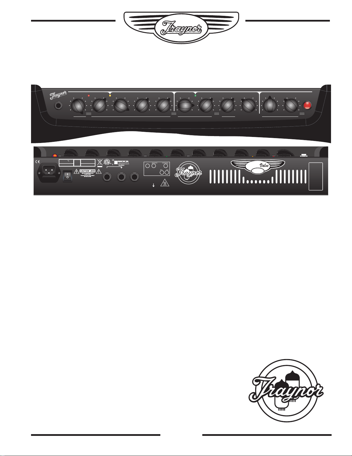
Introduction
The Traynor YCV50 is a professional all-tube guitar combo. It draws on the rich tradition of Traynor guitar amplifiers
and combines the best of vintage design combined with modern principles, manufacturing techniques, and technology.
Features
• 100% Designed & Manufactured in North America!
• All-tube design with two EL34 and three 12AX7A Premium tubes.
• A Single 12 inch Celestion Vintage 30® speaker for great classic sound and performance.
• Using all plywood for the construction of the cabinet guarantees the durability and rigidity that
made Traynor famous.
• Separate tone controls on each of the two channels (lead and clean) for flexibility.
• Classic Long-Style Accutronics® Reverb, with dual springs, for authentic vintage sound.
• External speaker jack for the ultimate in versatility.
• Traynor TFS-2B latching dual-footswitch, with 10-foot cable included.
• A special DC powered filament supply on preamp tubes ensures reduced hum.
• Auto-balancing bias supply means no need for matched pairs of output tubes or bias adjustments, allowing
extremely easy emergency tube replacement.
• Fully regulated power supply ensures ultra low noise.
• The best warranty in the business: a 2-year unlimited, transferable
“even if you break it” warranty (valid in the USA and Canada only).
1
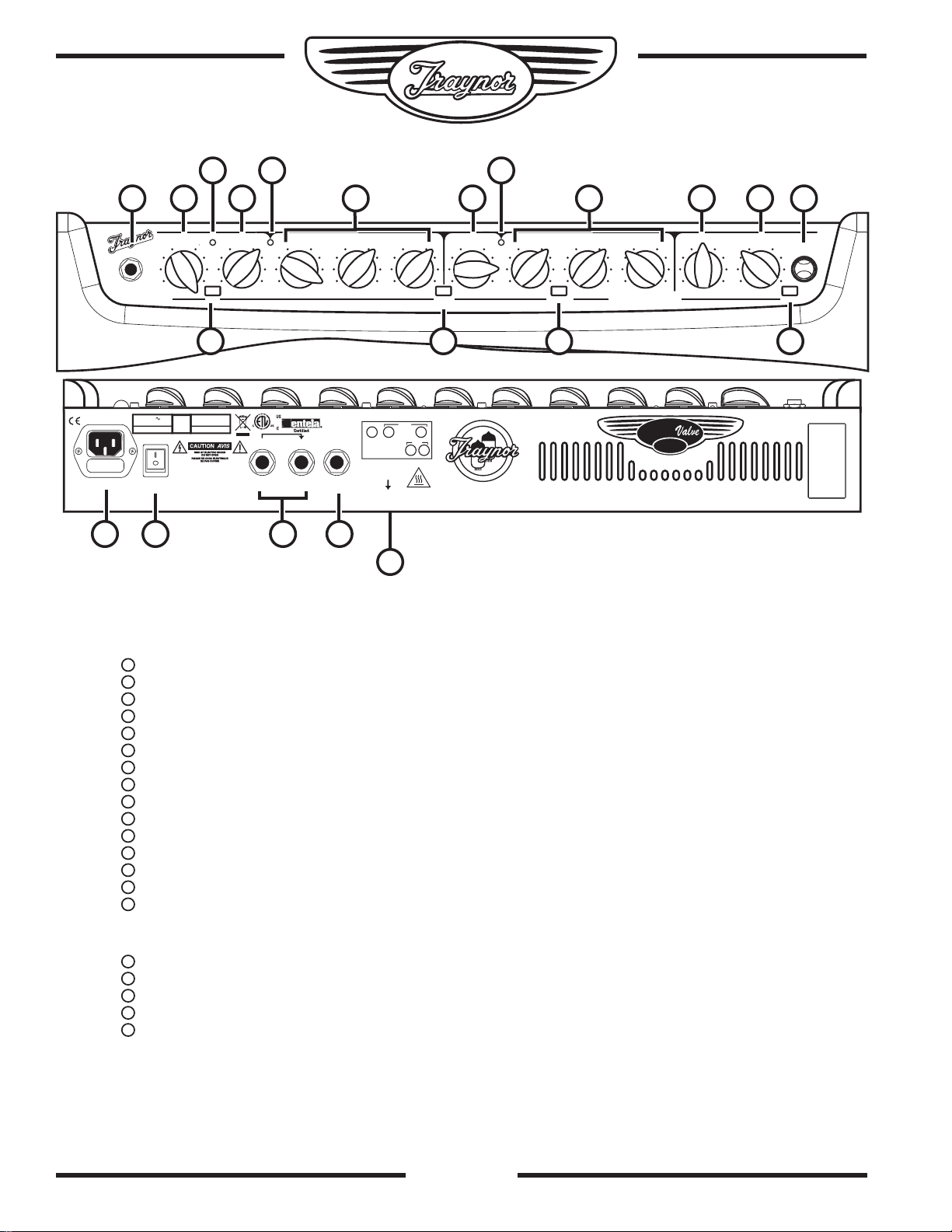
Chassis Layout
1
2
3
4
5
6
7
8
9
10
11
12
13
14
15
16
17
18
19
20
0510 0510
0510 0510 0510 0510
0510 0510 0510 0510
0510
CHANNEL
SELECT
Traynor Guitar Amplifier
GAIN
1 2
VOLUME
VOLUMEMIDDLEBASSTREBLE
MIDDLEBASSTREBLE MASTER VOLUM E
REVER B
POWER
STANDBYBRIGHTNES SBOOST
INPUT
MODEL TYPE: YS1003
Z359BR / 1v4
CAUTION: REPLACE WITH
SAME TYPE FUSE AND RATING
ATTENTION: UTILISER UN FUSIBLE DE
RECHANGE DE MEME TYPE ET CALIBRE
SEND
EFX / LINE FOOTSWITCH
RTN
CH. SELECT
/ BOOST
ON
EXTENSION
SPEAKER
POWER
ValveCustomCustom
50
TRAYNOR YCV50
DESIGNED & MANUFACTURED BY
YORKVILLE SOUND • Toronto, CANADA
POWER
EL34V4EL34
V5
PREAMP
SPLITTER
12AX7
V3
12AX7V212AX7
V1
DÉBRANCH É L’APPA REIL AVANT
DE REMPL ACER LES L AMPES
DISCONNE CT PO WER W HEN
REPLACIN G TUB ES
THIS UNIT MUST BE GROUNDED!
CET APPAREIL DOIT ETRE MIS Á TERRE!
DISCONNECT POWER
BEFORE SERVICING!
DEBRANCHER L’APPEREIL AVANT
D’ENLEVER LES COUVERCLES!
•
Q
U
A
L
I
T
Y
&
I
N
N
O
V
A
T
I
O
N
•
•
E
S
T
A
B
L
I
S
H
E
D
1
9
6
3
•
230V
50Hz 0.5A
120VAC
60Hz 1.0A
FUSE: T2.0A sloBlo
FUSE: T800mA
2
7
3
89145
6101112131415
1617181920
2
Top
Input jack – 1/4 inch phone jack.
Channel 1 Gain and Volume Controls.
Channel 1 Boost Switch – Activates the boost circuitry.
Boost LED – Illuminated Red when the boost is active.
Channel 1 Indicator LED – Illuminates Yellow when active.
Channel 1 Tone Controls – Treble, Bass, and Middle.
Channel Select Switch – Channel 1 is optimized for lead, Channel 2 for clean sound
Channel 2 Volume Control.
Channel 2 Indicator LED – Illuminates Green when active.
Channel 2 Brightness Switch – Add sparkle to your clean sound.
Channel 2 Tone Controls – Treble, Bass, and Middle.
Master Volume – Controls the overall level of the amplifier.
Reverb Control – Adjusts the Accutronics® reverb level for both channels.
Standby Switch – Activates standby mode to keep the tubes warm while the amp is not in use.
Power Indicator Jewel – Illuminates Red when in Active mode, and Yellow when in Standby mode.
Rear
Fuse and Power Cord
Power Switch.
Send / Rtn (Efx/Line) jacks – 1/4 inch phone Input and Output jacks.
Channel Select Footswitch jack – uses a 1/4 inch TRS standard latching dual-footswitch.
Extension Speaker jack –1/4 inch phone jack.
2

Channel 1 5 7
2
4
6
11
10
12
13
15
20
Channel 1 is the lead/overdrive channel and is
selected in one of two ways, via the Channel Select
switch on the control panel, or via the Channel Select
button on the supplied footswitch* pedal. A Yellow
LED located next to the Channel 1 Volume control
illuminates when Channel 1 is active.
*Note: Plugging in the footswitch deactivates the panelmounted Channel and Boost controls.
Gain & Volume Controls
Channel 1 uses a Gain control in conjunction with a
Volume control to control the amount of tube-based
overdrive and volume. The Gain control is used to adjust
the amount of overdrive, while the Volume control allows
you to set the actual loudness of the amplifier.
Boost Switch 3
A boost circuit is included to help you achieve ‘a-bitmore’ overdrive for leads. The boost can be selected
via the front panel switch or through the supplied
footswitch pedal. A Red LED illuminates to indicate
when the boost is active.
Channel 1 Tone Controls
The Treble, Bass, and Middle tone controls are used to help
you shape your sound. They are post-gain and pre-volume.
These are active only when Channel 1 is selected.
Channel 2 8 9
Channel 2 is the clean channel and thus has no Gain
control. In other respects the layout is the same as that
of Channel 1, with independent Volume and Treble,
Bass, and Middle tone controls. When channel 2 is
active the green LED located next to the Channel 2
Volume control is illuminated.
Brightness Switch
Channel 2 includes a Brightness switch that activates
a circuit to provide additional treble boost to help make
your tone sparkle.
Master Controls
Master Volume Control
The Master Volume control adjusts the overall volume
of the amplifier.
Reverb Control
The Master Control section also includes a rotary
Reverb control that adjusts the overall reverb level
for both channels. The YCV50 is equipped with
a long-style Accutronics® dual-spring reverb for
authentic vintage reverb.
Standby Switch & Indicator 14
This switch controls the high voltage power being supplied
to the tubes. This mode effectively keeps the tubes warmed
up when the amp is not in use. The large, jewel indicator on
the front panel glows Red when the amp is fully poweredup and changes to Yellow when the high voltage circuit has
been turned off. Putting the amp into Standby mode (i.e.
during set breaks) shuts off the amplifier output stage and
effectively increases tube life by reducing wear on the tubes.
EFX / LINE Send & Return Jacks 18
The Send and Rtn jacks of the YCV50 allow convenient
use of an external effect unit. Simply connect a 1/4 inch
phone cable to the Send jack of the YCV50 and then
connect this cable to the Input of your effects unit. To send
the processed signal back to the YCV50, connect the
output of the effects unit to the Rtn jack of the YCV50.
The 1/4 inch TRS Send jack can be used as part of
an effects loop in conjunction with the Rtn jack. It can
also be used as a direct line out (preamp-out). The 10dBu output is ideal for most guitar effects pedals and
professional signal processors. You can also use this
output to slave the YCV50 with another guitar amplifier
by plugging into the Rtn jack of the slave amplifier.
The 1/4 inch TRS Rtn jack can be used as your return
jack for your effects loop. It accepts an input signal that
is passed to the power amplifier, so it can be used as a
power amp in. The Master Control section regulates the
signal, so you can add Reverb as well as Presence.
Footswitch Jack 19
Connecting a footswitch to the 1/4 inch TRS Footswitch
jack deactivates the control panel mounted Channel
Select and Boost switches. These functions are then
activated exclusively by the pedal. The included
footswitch features dual-latching switches, each with a
separate LED indicator.
The switching is accomplished with internal relays
so there is no audiable noise flowing through the
footswitch cable. Footswitch-induced noise is never an
issue. The YCV50 is compatible with most aftermarket
latching dual-footswitch pedals.
External Speaker Jack/s
These under-the-chassis mounted 1/4 inch jacks
allow convenient connection of an 8-ohm external
speaker cabinet. If you disconnect the internal 12
inch Celestion® speaker, you can connect up to
two 8-ohm external cabinets.
3
 Loading...