

Yorkville Sound AP 312 User Manual
OWNER'S MANUAL
MANUEL DE L'UTILISATEUR
Manual-Owners-ap312-3v3.pdf

IMPORTANT SAFETY INSTRUCTIONS
safety-4v1.eps Aug 26/05
CAUTION:
TO REDUCE THE RISK OF ELECTRIC SHOCK, DO
NOT REMOVE COVER (OR BACK).
NO USER SERVICEABLE PARTS INSIDE.
REFER SERVICING TO QUALIFIED
SERVICE PERSONNEL.
INSTRUCTIONS PERTAINING TO A
RISK OF FIRE, ELECTRIC SHOCK,
OR INJURY TO PERSONS
Read Instructions
The Owner’s Manualshould be read and understood
before operation of your unit. Please, save these instructions for future reference.
Packaging
Keep the box and packaging materials, in case the unit
needs to be returned for service.
Warning
When using electric products, basic precautions should
always be followed, including the following:
Power Sources
Your unit should be connected to a power source only of the voltage
specified in the owners manual or as marked on the unit. This unit has
a polarized plug. Do not use with an extension cord or receptacle
unless the plug can be fully inserted. Precautions should be taken so
that the grounding scheme on the unit is not defeated.
Hazards
Do not place this product on an unstable cart, stand, tripod, bracket or
table. The product may fall, causing serious personal injury and serious
damage to the product. Use only with cart, stand, tripod, bracket, or
table recommended by the manufacturer or sold with the product.
Follow the manufacturer’s instructions when installing the product and
use mounting accessories recommended by the manufacturer.
The apparatus should not be exposed to dr
ipping or splashing water;
no objects filled with liquids should be placed on the apparatus.
Te
rminals marked with the “lightning bolt” are hazardous live; the
external wiring connected to these terminals require installation by an
instructed person or the use of ready made leads or cords.
No naked flame sources, such as lighted candles, should be
placed on the apparatus
.
Power Cord
The AC supply cord should be routed so that it is unlikely that it will be
damaged. If the AC supply cord is damaged DO NOT OPERATE THE UNIT.
Service
The unit should be serviced only by qualified service personnel.
AVIS:
AFIN DE REDUIRE LES RISQUE DE CHOC ELECTRIQUE,
N’ENLEVEZ PAS LE COUVERT (OU LE P
ANNEAU ARRIERE)
NE CONTIENT AUCUNE PIECE
REPARABLE PAR L’UTILISATEUR.
CONSULTEZ UN TECHNICIEN QUALIFIE
POUR L’ENTRETIENT
INSTRUCTIONS RELATIVES AU RISQUE
DE FEU, CHOC ÉLECTRIQUE, OU
BLESSURES AUX PERSONNES
Veuillez Lire le Manuel
Il contient des informations qui devraient êtres comprises
avant
l’opération de votre appareil. Conservez S.V.P. ces
instructions pour consultations ul
térieures.
Emballage
Conservez la boite au cas ou l’appareil devait être
retourner pour réparation.
Attention:
Lors de l’utilisation de produits électrique, assurez-vous
d’adhérer à des précautions de bases incluant celle qui
suivent:
Alimentation
L’appareil ne doit être branché qu’à une source d’alimentation
correspondant au voltage sp
écifié dans le manuel ou tel qu’indiqué sur
l’appareil. Cet appareil est équipé d’une prise d’alimentation polarisée.
Ne pas utiliser cet appareil avec un cordon de raccordement
à moins
qu’il soit possible d’insérer complètement les trois lames. Des
précautions doivent êtres prises afin d’eviter que le système de mise à
la terre de
l’appareil ne soit désengagé.
Risque
Ne pas placer cet appareil sur un chariot, un support, un trépied ou une
table instables.
L’appareil pourrait tomber et blesser quelqu’un ou subir
des dommages importants. Utiliser seulement un chariot, un support,
un tr
épied ou une table recommandés par le fabricant ou vendus avec
le produit. Suivre les instructions du fabricant pour installer l’appareil et
utiliser les accessoires recommand
és par le fabricant.
Il convient de ne pas placer sur
l’appareil de sources de flammes
nues, telles que des bougies allumées.
L’appeil ne doit pas être exposé à des égouttements d’eau ou des
éclaboussures et qu’aucun objet rempli de liquide tel que des vases
ne doit
être placé sur l’appareil.
Les dispositifs marqu
és d’une symbole “d’éclair” sont des parties
dangereuses au toucher et que les
câblages extérieurs connectés à
ces dispositifs de connection ex
térieure doivent être effectivés par un
opérateur formé ou en utilisant des cordons déjà préparés.
Cordon d’Alimentation
Évitez d’endommager le cordon d’alimentation. N’UTILISEZ PAS
L’APPAREIL si le cordon d’alimentation est endommagé.
Service
Consultez un technicien qualifié pour l’entretien de votre appareil.
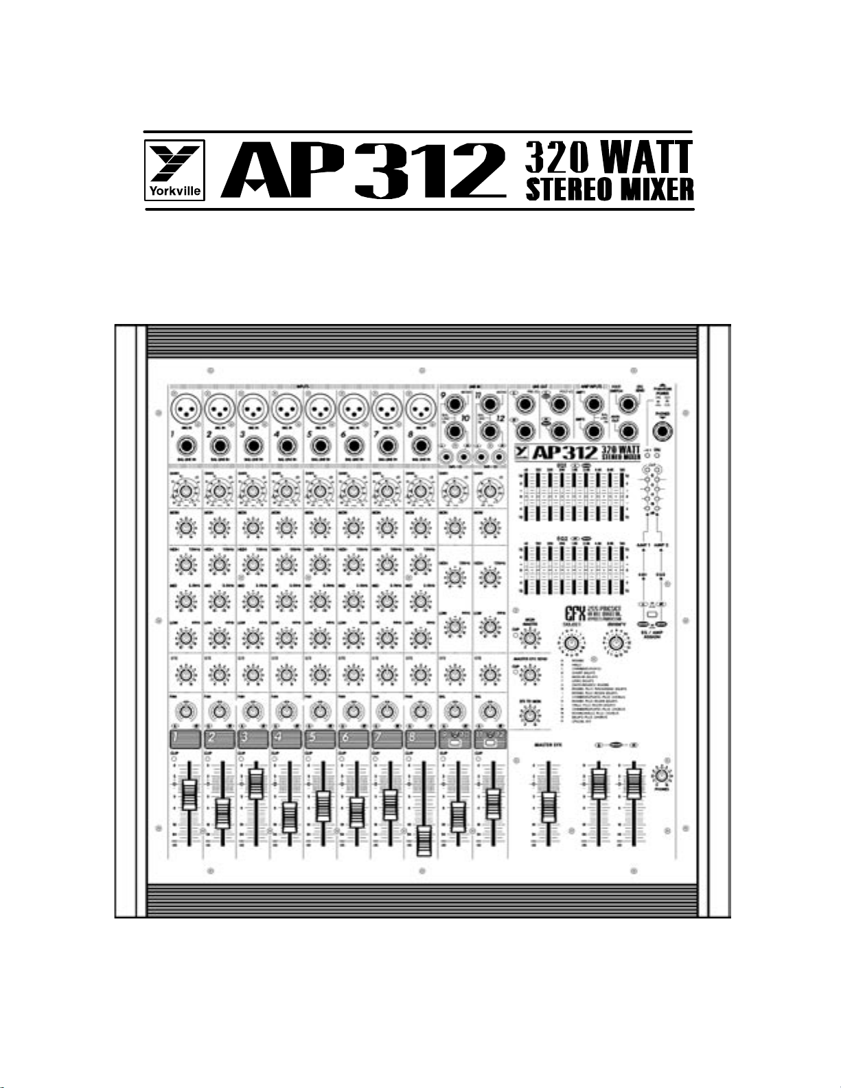
Introduction
Your new AP312 Mixer/Amplifier is designed and built to provide long-term trouble free
performance. Drawing on over thirty years of experience in the design and manufacture
of powered mixing consoles, Yorkville engineers were able to optimize the design of the
AP312 to include comprehensive features such as rack mountability, quiet internal fan
cooling, two stereo input channels with cue buttons, headphone monitoring of both the
cue and monitor busses, phantom powering, dual 9-band EQ’s, power amp channels
and EQ’s assignable to Left/Right stereo operation or Main/Monitor mono operation, 255preset digital signal processing, dual level meters and 320 watts of stereo power built-in.
Terminology
• 3-pin microphone inputs are referred to as XLR connectors.
• 1/4-inch jack sockets are called phone connectors.
• Balanced 1/4-inch inputs or outputs are called TRS or Tip-Ring-Sleeve
• Master control and mixing channels are called busses.
• Overload indicators are called Clip LED’s.
• Patch cables with dual conductors plus shielding and ring-tip-sleeve (stereo) 1/4inch phone plugs are referred to as balanced patch cables.
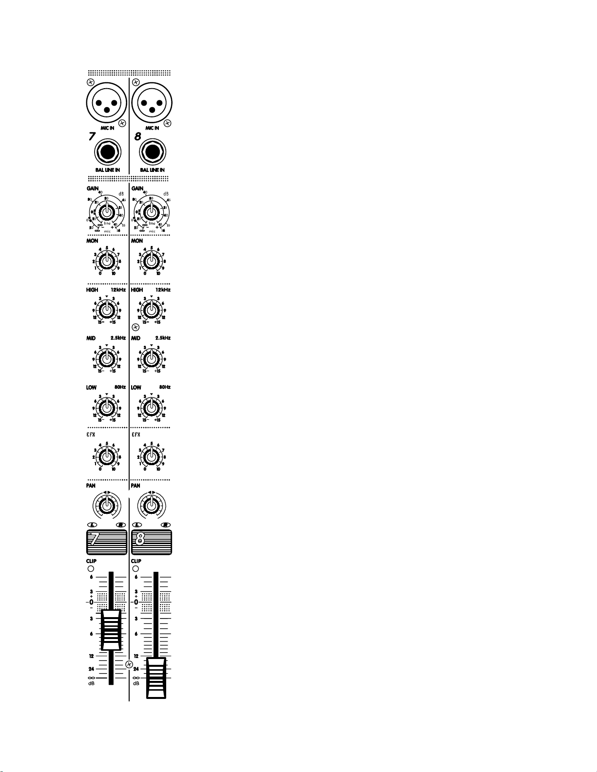
Basic Features
Channels 1 - 8
• XLR MIC and balanced TRS LINE inputs new, with low-noise input circuit
design.
• Balanced LINE inputs accept either balanced or unbalanced lines.
• PHANTOM power (24 volts).
• 78dB of input GAIN-adjustment range.
• MONitor send controls are pre-EQ and pre-fader for a totally independent monitor mix.
• Three-band EQ with +/-15dB of range.
• Post-EQ, post-fader, EFX (effects) send controls.
• PAN controls provide constant gain levels at all settings.
• Increased circuit headroom and gain for a more flexible mix.
• Gold internal bus-interconnects for long life and maximum signal integrity.
• Pulse-stretching CLIP LED’s indicate even the briefest peaks and fire at 3dB,
well before the onset of actual clipping at any and all active channel stages.
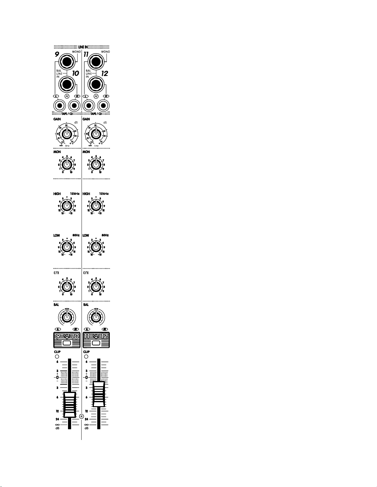
Stereo Channels (9/10, 11/12)
(see diagram on following page)
• Left and Right 1/4” balanced TRS LINE inputs accept either balanced or
Unbalanced lines.
• The LEFT TRS input may be used for connecting a mono source and will
internally patch it to the RIGHT channel input circuitry.
• LEFT and RIGHT RCA inputs.
• LOW and HIGH frequency shelving EQ.
• BALANCE control
• CUE buttons let you preview these channels through headphones with the level
faders shut off.
1
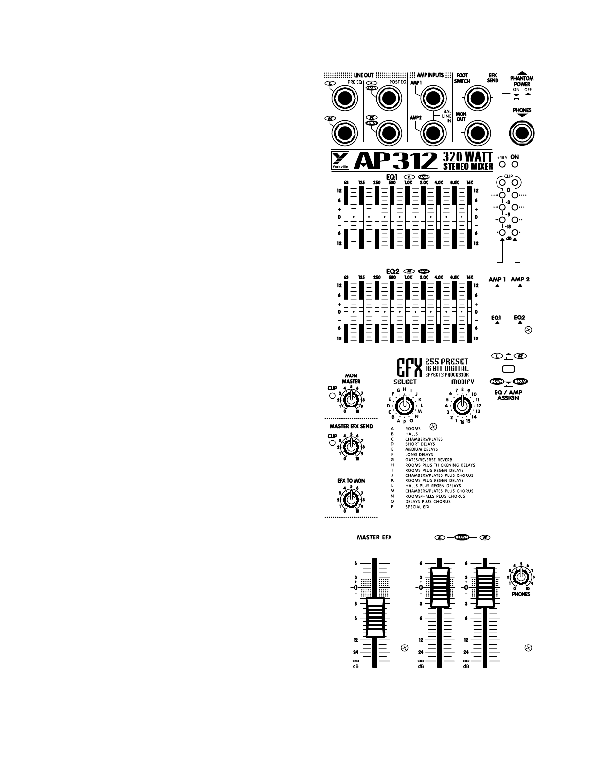
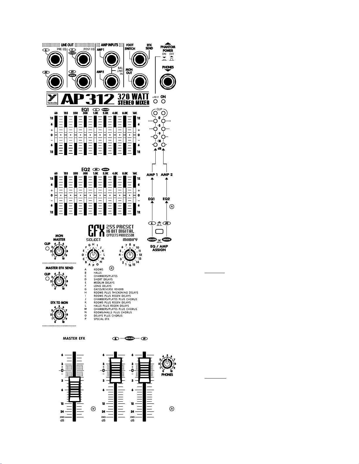
Master Features
• SELECT and MODIFY masters provide up 255 presets of
reverb, delay and other effects.
• Separate EFX TO MAIN and EFX
TO MONitor masters.
• Internal effects subsystem, based
on the A.R.T. 16-bit digital
effects processor, delivers crystal
clear performance.
• MASTER EFFECTS fader lets
you insert the internal effect
quickly and easily.
• MASTER EFX SEND control
with it’s own CLIP LED to help
prevent overloading the circuitry at this stage.
• LEFT and RIGHT MAIN faders
- in fact all faders - feature 0dB
reference markings.
• MONitor master features its own
CLIP LED to help you avoid
monitor distortion.
• PHONES level controls the
headphone amplifier which
monitors the CUE bus when a
CUE button is depressed and the
MONitor bus when it is not.
• The MAIN - MONitor EQ/AMP
push-button lets you configure
the AP312 as either left-right
stereo with a separate nine-band
EQ for each channel, or as a
mono system with one amplifier
channel and EQ for the MAIN
PA speakers and the other amplifier channel and EQ for the
MONITOR speakers.
2
Power Amplifier Features
• A total output of 320 watts
with well-proven, reliable
AUDIOPRO technology.
• Industry leading specifications for
distortion, damping, and efficiency.
• Comprehensive protection
against low or even shorted
loads, overheating.
• Standard Dual 1/4-inch output connectors.
Feature Details & User Tips
Channnel Strips
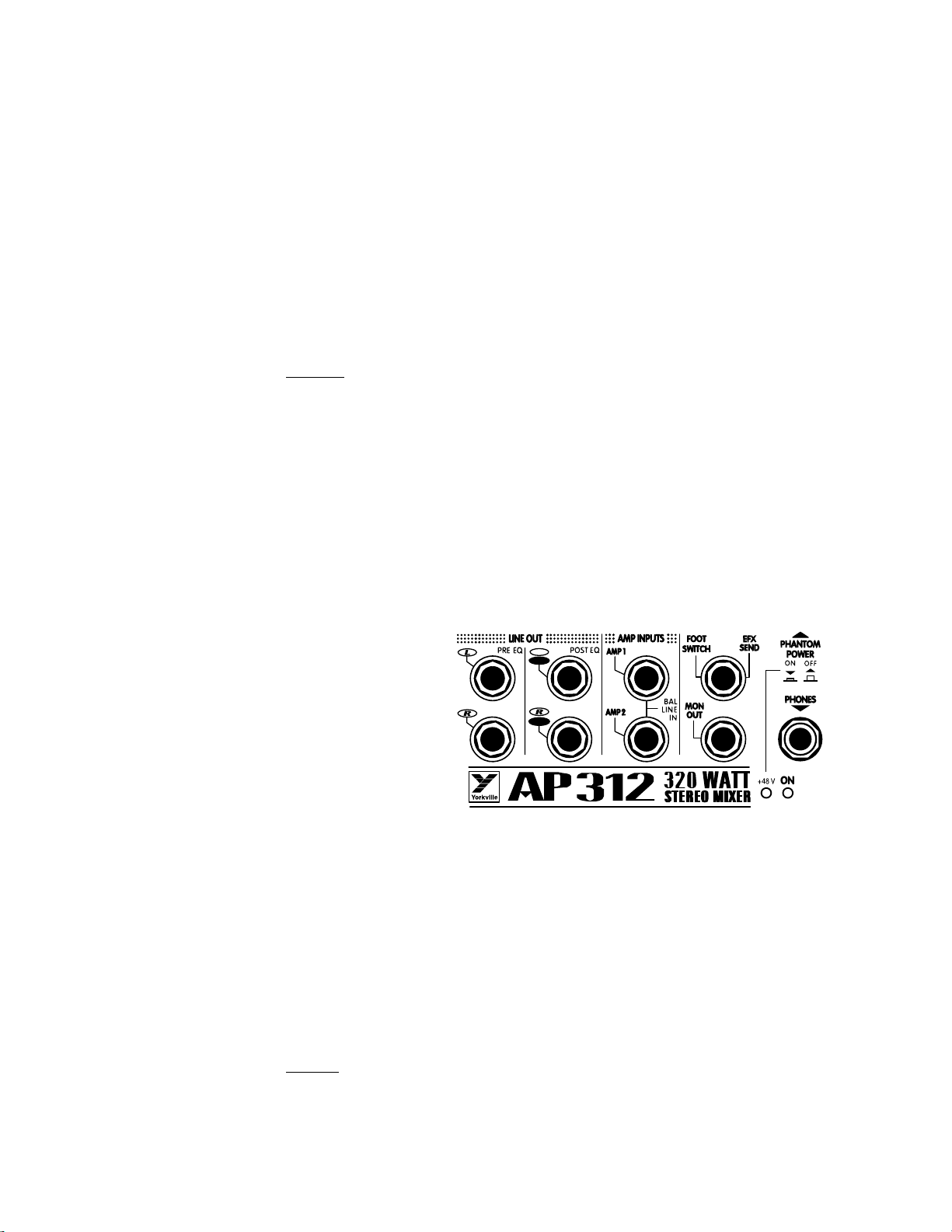
Inputs
Each channel has both a MIC and LINE input (except for channels 9/10 & 11/12
which have RCA type inputs as well as 1/4-inch TRS inputs). The LINE input will
accept either balanced or unbalanced signals from all types of sources and the MIC
input is optimized for low-impedance microphones. The LINE input is Tip-RingSleeve balanced, with the Tip in phase, the Ring reverse phase and the sleeve,
Ground. The XLR is wired Pin 1= Ground, Pin 2 = in phase & Pin 3 = reverse phase.
This configuration is the standard throughout the world.
User tip: Problem; Hum and Buzz When Source is Unbalanced...
Unbalanced connections may be made to the LINE input with an unbalanced
shielded cable. However, field or leakage-induced ground currents between separate
pieces of equipment can sometimes produce hum and buzz. Most electronic instruments, for example, still use unbalanced connections. If the equipment has more than
one output feeding the mixer, even floating the circuit ground may not help.
CAUTION: We urge you to NEVER remove the ground-pin on the AC cord or other-
wise disable the earth safety Ground connection as doing so can expose you to a seri-
ous shock hazard. Additionally, your radio interference problems will likely increase
and in some cases your hum problems will get even worse.
What to do: Hum and buzz can be safely reduced or eliminated with the AP312’s
input balancing, even when the signal source is unbalanced, Simply use standard TipRing-Sleeve balanced patch cables. However, in some worst-case instances it may be
necessary to create a special patch cable. In this case, use a 1/4-inch TRS (stereo) cable.
Attach a 1/4-inch TRS (stereo) plug to the end which will plug into the mixer’s
balanced-input as follows; 1) solder shield to Sleeve, 2) solder wire #1 to Tip, 3) solder wire #2 to Ring. Now attach the mono plug to the other end of the cable as follows: 4) solder the shield and wire #2 to the Sleeve, 5) solder wire #1 to the tip. Now
connect this mono end to the output of the unbalanced piece of equipment and the
stereo end to the AP312’s LINE input.
This technique will always reduce hum, and it can be used to connect any equipment
having a Balanced INPUT to any other equipment having an Unbalanced OUTPUT.
Phantom Power Button & LED
Located on the back panel near the SPEAKER outputs, this push-button activates the 24
Volt PHANTOM POWER feature built into the AP312. When the PHANTOM POWER is
activated, the +24V LED on the front panel (just below the PHONES jack) will illuminate.
Now you may connect condenser microphones to any channels without the need for
external power supplies. You may also connect dynamic mics to any channels with the
PHANTOM POWER activated without any problems or loss of sound quality.
Gain Control
With signal applied to the input, adjust this control so that occasional flashes of the
CLIP LED are observed. This will ensure that the signal level fits comfortably within
the channel strip’s headroom ~ low enough to prevent distortion, and yet high
enough to preserve the signal to noise ratio. This control covers a wide range of 78
dB, so it may seem rather sensitive until you’re used to it.
Monitor Send
The MON send control is pre-EQ & pre-fader. This means that the bit of channel signal
it sends to the MASTER MONitor bus is tapped off at a point ahead of both the channel
EQ circuitry, and the level fader. As a result it is not affected by either of these features.
This means that you have a totally flat signal to work with and custom-equalize for the
3
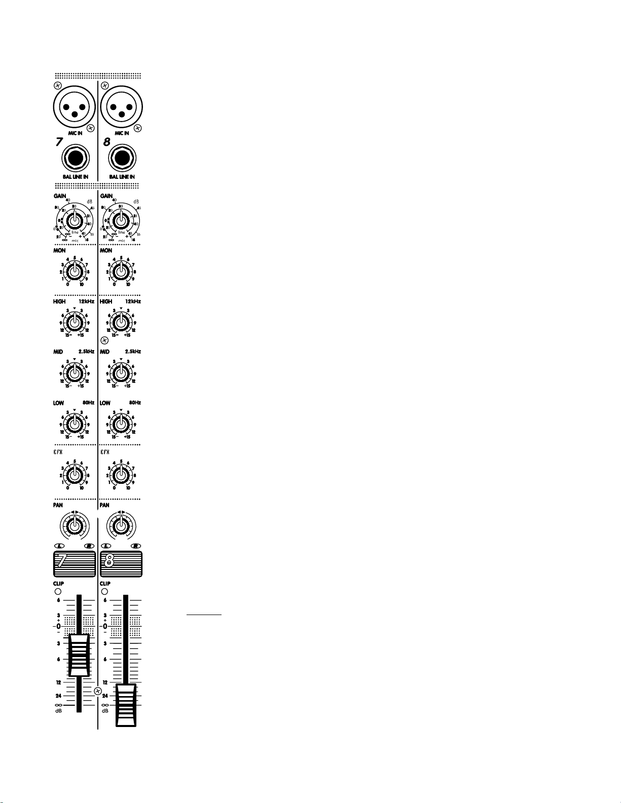
monitor system using the AP312’s EQ2 equalizer or an external EQ patched between
the AP312’s MON OUT jack and the external power amp you are using for monitors.
User tip: In order to shut a channel off completely, it will be necessary to turn down
the MON send, as well as the channel fader.
3-Band EQ
Equalization is varied by three controls labeled HIGH, MID, and LOW. Each control
can either boost or cut the amplitude of its frequency band by 15dB. This is a considerable amount of gain change, roughly equivalent to a 150% variation in audible
loudness. It is therefore wise to use boost settings of not more than +3dB to +6dB in
order to avoid feedback and/or distortion.
User tip: On the other hand, -15dB of CUT-capability can come in handy for solving
certain mic or line problems. For example, substantial LOW and HIGH cuts can help get
rid of feedback plus puffing and thumping noises from harmonica mics. Flattop guitar
mics or transducers can often benefit from a slight MID cut to fatten the sound, and
direct or miked bass inputs usually benefit from a fairly substantial LO cut to avoid main
system distortion (do NOT put bass through the monitor system)
3-Band EQ - Channels (9/10 & 11/12)
LOW & HIGH shelving EQ is provided for the stereo channels. Here again, the gain
range is plus/minus (+/-)15dB. As a result, care should be taken in adjusting the EQ
above center position as a small adjustment can represent a large gain change.
Effects Send
The EFX send control varies the amount of post-EQ, post-fader channel signal
sent to the master EFX bus. The output of the EFX bus goes first to the EFX SEND
/ FOOTSWITCH jack and then to the internal 16-bit processor. The output of the
effects processor then goes to the MAIN master section to be mixed with the signals
going there direct from the input channels.
Cue Button - Channels (9/10 & 11/12)
The CUE feature enables you to preview channel signals via headphones before they
go to the main and/or MONitor bus. The CUE signal is post-EQ so that the channel
equalization will be in effect through the headphones. However, it is pre-fader so you
will need to shut the channel off through the mains and monitors when cueing. Use
the PHONES LEVEL to adjust cueing volume.
To employ this feature, simply follow these steps:
a) Connect a tape deck or CD-player to channel 9/10 or 11/12..
b) Pull the channel fader all the way down and turn the MON send to 0.
c) Depress the CUE button. Now that channel will have prominence through
your headphones.
d) Cue up your tape or CD track through the phones, then put it on play hold/
pause.
e) When you are ready to insert the recorded material, simply punch the CUE
button into the up position, then take the recorded material off play hold/
pause and bring up the channel fader and MON send to the desired mix levels.
User tip: When you have inserted the cued material into the monitors, you will be
able to adjust its monitor mix level via headphones since the monitor bus signals
are always present through the phones when no channels are on CUE. The recorded
material’s main mix level will be audible to you through the main speaker system
Pan or Balance Controls
This control directs the post-fader output of the channel between the LEFT and RIGHT
MAIN masters. In a stereo setup, the PAN/BALance can be used to position the aural
image of the channel left or right within the stereo listening field.
4
Channel Faders
This adjusts the levels of both the post-EQ channel signal headed directly for the LEFT and RIGHT MAIN master bus (via the PAN/BAL pot), and the EFX send signal
headed for the master EFX bus. The channel fader does
not control the MONitor send level.
Clip LED
The channel CLIP LED watches all the active electronic
stages in the channel circuit. Whenever any stage’s
signal peak approaches clipping to within 3dB, the
CLIP LED circuitry captures and displays this event. See
under GAIN control for more about this featur
Monitor Master & Clip LED
This control regulates the overall level of the master
MONitor bus. The CLIP LED, like the others, fires at 3dB
below the onset of actual clipping so that a small amount
of activity is quite acceptable. If the LED flashes frequently, reduce the MON MASTER setting, or possibly one or
more of the channel MON send settings. The output of
the MON MASTER bus goes to the MON OUT jack. It
also goes to the EQ/AMP ASSIGN button where it can
be directed to the EQ2 equalizer and then to the RIGHTchannel of the built-in stereo power amplifier. Regardless
of the EQ/AMP ASSIGN button’s operation, the MONitor
signal remains available at the MON OUT jack so that it
can be used to drive an additional amp/speaker system.
Mon Out Jack
Located in the upper right area beside the PHONES
jack, MON OUT is the output of the monitor bus. It is
at line level (do not connect speakers to it directly) and
unbalanced. Connect your monitor power amp or powered monitors here.
User tip: If another monitor system is in use, perhaps
full-range enclosures running off the main PA mix
as side-fills, you could connect a tape deck here
to record live performances. Plug a single 1/4-inch
male-to-dual 1/4-inch female Y adapter into the
MON OUT jack. Now simply run two of the appropriate patch cables (probably 1/4-inch male-to-RCA
male) into the tape deck’s L&R line level inputs. You
will now have the advantage of being able to mix for
recording, independent of the PA mix.
Left & Right Main Masters
EQ/Amp Assign Button
The MAIN master faders receive signals from the channel PAN/BAL controls and determine the output signal
levels at the L&R PRE-EQ LINE OUTPUT jacks.
User tip: Regardless of the ASSIGN button’s function,
the PRE-EQ LINE OUTPUT jacks will always carry
the unequalized L&R stereo mix. This can be useful
if you are recording the live performance.
5
The MAIN faders also determine the signal levels destined for the EQ/AMP ASSIGN
button where they are directed as follows:
a) Up in the L&R position, the ASSIGN button directs the Left & Right MAIN
master signals to EQ1 and EQ2 respectively. Thereafter they go in two directions at once - to the L&R inputs of the built-in power amplifier and to the
L&R POST EQ LINE OUTPUT jacks.
b) Down in the MAIN/MON position, the ASSIGN button also does two things.
First, it sums some of the LEFT and RIGHT MAIN signals into a single mono
signal and directs it to the input of EQ1, the output of which is then split and
goes to both the LEFT power amp channel and to the POST EQ MAIN (L)
LINE OUTPUT jack. Secondly, the button takes some of the MON MASTER’s
output signal and routes it to the input of EQ2, thereafter to be split and routed to the RIGHT channel of the built in power amplifier and to the POST EQ
MON (R) LINE OUTPUT jack.
User tip: The stereo operating mode of the AP312 would be with the EQ/AMP
ASSIGN button up in the L&R position. This would supply up to 320 watts of stereo
power (160 watts/channel) plus separate L&R 9-band EQ’s for the main system speakers. Power and equalization for the monitors would come from a separate power
amplifier and graphic EQ. With the EQ/AMP ASSIGN button down in the MAIN/
MON position, you now have 160 watts of mono power @ 8 Ohms plus a single 9band EQ for the main PA speakers, also 160 watts @ 8 Ohms and a single 9-band EQ
for the monitors. Connect main PA speakers to the AMP 1 SPEAKEROUTPUT’s and
monitors to AMP 2 SPEAKER OUTPUTS. See under SPEAKER CON-NECTIONS for
suggested speaker impedances.
Pre & Post EQ Line Outputs
These are the outputs of the L&R main mixing busses. They are all at line level (do
not connect speakers directly) and unbalanced. The PRE EQ outputs are not affected
by either of the graphic equalizers. The stereo main mix is available from them at all
times, regardless of the EQ/AMP ASSIGN button setting. These would be available
for connecting a secondary mixer perhaps for a house PA, broadcast and/or recording purposes. These outputs,
although not balanced, have
been designed to supply the
noise-canceling benefits of
balanced outputs as long as
the inputs of the unit (power
amp or mixer) you are connecting them to have balanced inputs, and you use
TRS balanced cables
6
The POST EQ output
signals are affected by the graphic equalizers. They are also affected by the EQ/AMP
ASSIGN button. With the button up in the L&R MAIN position, these jacks receive
the output of EQ1 at the L MAIN jack and EQ2 at the R MON jack. With the EQ/AMP
ASSIGN button down in the MAIN/MON position, the L MAIN jack receives mono
(left & right mixed together) main mix signal from EQ1 and monitor signals from EQ2.
The POST EQ outputs are best for driving power amplifiers whether for main or monitor speaker systems.
EQ1 & EQ2 Graphic Equalizers
These are 9-band EQs having standard ISO octave-spaced frequencies. The Q-factor is greater in cut-mode than in boost-mode, which is desirable when using the EQ
for feedback control. Up to 12dB of cut or boost is available. For more information
about their internal routing, see under LEFT & RIGHT MAIN MASTERS and EQ/AMP
ASSIGN BUTTON above.
User tip: As with all graphic EQ’s, minimal variations above or below center settings
are always recommended. The only exception to this rule might be in the fight against
feedback, but even there the ideal solution is to separate the offending speaker from the
offending mic or at least aim them in different directions. This way the whole system’s
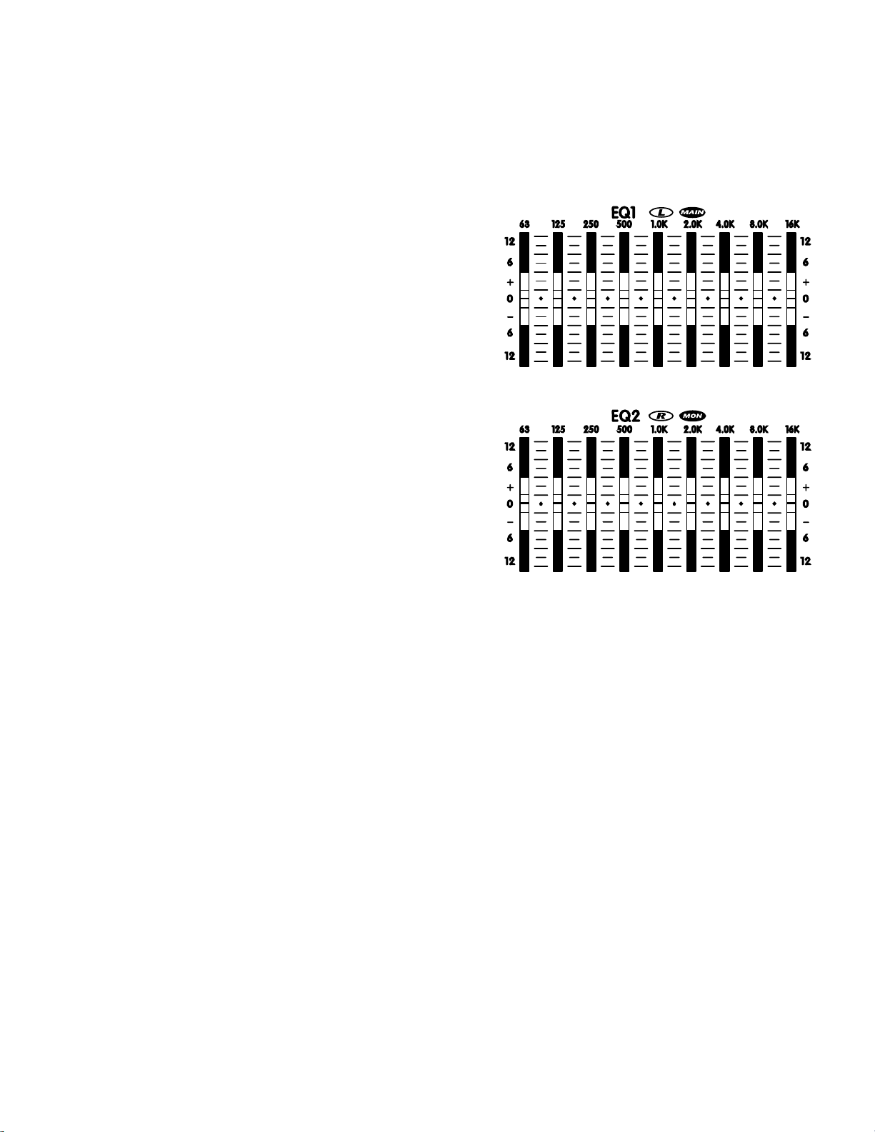
natural frequency response does not have to be compromised because of one mic
and one speaker. Ideally, a Real-time Frequency Analyzer and Pink Noise would be
employed before the audience arrives to help you pre-adjust the EQ(s) to cut obvious
system/room response spikes likely to cause feedback later on. Without such devices
you can achieve a vaguely similar result by simply turning up the level until a mic feeds
back, then reacting accordingly (this may or may not involve the EQ’s). In any case, the
prime suspect whenever
feedback starts is always
a monitor. A graphic EQ
with a MIC level input can
be inserted between the
offending mic and the mixer
input to solve that channel’s
problem without altering
the whole monitor system
response
Effects Bus Routing Overview
The AP312’s effects bus
receives and mixes down all
the channel EFX SEND signals. Its output is regulated
by the MASTER EFX SEND
control and is internally
routed, first to the EFX SEND
/ FOOTSWITCH jack. This
is a switching jack which
normally allows the signal
to proceed internally to the
effects processor. But when
a jack is inserted here, the
switching function reroutes
the effects bus signal out the
jack to either an on/off footswitch or whatever you have patched it to, probably an
external effects unit, or possibly something else if you have decided to do without
effects and perhaps feed a broadcast transmitter or recording unit. In any case, the
output of the internal digital effects processor is permanently routed to the MASTER
EFX fader and thereafter to the LEFT & RIGHT MAIN MASTER busses, also to the EFX
to MON master control and thereafter to the monitor bus.
User tip: The EFX SEND/FOOTSWITCH jack can be used as an auxiliary mono output. The internal effects will not be disabled and can be used as per normal.
Master EFX Send Control & Clip LED
For the quietest performance, you should run the MASTER EFX SEND level as high as
possible without causing distortion. With the channel EFX SEND controls turned up
roughly half-way and signals coming into the channels, increase the MASTER EFX SEND
level until some EFX CLIP LED activity is observed, then turn it back down slightly
until the flashing stops. You may now re-adjust the channels EFX levels as desired. The
MASTER EFX SEND may now be used to tailor the EFX mix on all channels at once.
7

Digital Effects Processor
The internal Digital Effects Processor is a
full 16 bit, 20kHz bandwidth DSP-based
effects subsystem developed by Applied
Research & Technology in Rochester,
New York. It has been custom programmed with 255 effects ranging from
reverb to echo and special effects.
The selection of effects was determined in
collaboration with a panel of sound engi-
neers experienced in live performance mix-
ing. The panel was asked to choose effects,
which would be of the most practical use
in actual, live performance situations. As a
result you will find the internal system to be
more than adequate for most application
EFX Footswitch/Send Jack
A standard on/off footswitch (optional)
plugged into this jack will enable you to
turn the internal effects system on and off.
Optionally, this jack may be employed to
feed the EFX signal to an external effects
unit the output of which could be returned
via an input channel - perhaps channel
9/10 or 11/12 if the effects unit is stereo. In
this mode, the channel fader would become the master effects return control, therefore be sure to set that fader fairly low and adjust to desired levels. Be sure to turn the
EFX send control off in order to avoid creating a loop. Also, be sure to pull the EFX
MASTER fader down to the off position.
Phones Jack, Level Control & Sources
The PHONES jack accepts standard stereo headphones and is located in the upper
right area of the panel. The PHONES level control is located in the lower right area.
The source for all headphone signals is the MONitor bus until a CUE button is
depressed at which time only the cued channel can be heard through the phones.
Level Meters
These meters follow either the Left and Right MAIN bus activities or a mono mix of
the mains on the Left-meter and monitors on the Right-meter, all depending on the
position of the EQ/AMP ASSIGN button. If either or both CLIP lights at the top of the
level meters is flashing too much of the time, lower the appropriate MAIN MASTER
level to avoid possible distortion on peaks.
Amp 1 & 2 Inputs
These are switching jacks, which enable you to directly access either or both channels of the built-in power amplifier while disconnecting them from normal internal
functions. This permits you to insert an external-EQ, a processor/crossover (e.g. élite)
or a compressor/limiter between the mixer section’s POST EQ LINE OUTPUTS and
the AMP 1 & AMP 2 INPUTS thus providing the 100% signal processing essential for
these functions to work properly.
User tip: If you have an electronic-crossover or processor/crossover, you can drive
subwoofers and full-range cabinets in a biamped system with the AP312. The hookup
goes as follows:
1. With the EQ/AMP ASSIGN button down in the MAIN/MON position, run a patch
cable from the POST EQ MAIN (L) LINE OUTPUT to the input on an electronic
crossover/processor.
2. Now run a second patch cable from the low-frequency or subwoofer output on
the crossover to the AP312’s AMP 1 INPUT and a third patch cable from the
crossover’s high-frequency or full-range output to the AP312’s AMP 2 INPUT.
8

3. Now connect one 8 ohm subwoofer to the AMP 1 SPEAKER OUTPUT jack and one
8 ohm full-range cabinet to the AMP2 SPEAKER OUTPUT jack.
4. The complete system
is now functional, not
including monitors.
How-ever, if you need
to vary the comparative volume levels of the
subwoofer/s relative to
the full-range cabinets,
another setup will be
required with an external power amp for the
subwoofers or employing
powered subwoofers.
In that system, AMP 1 would be for full-range speakers and AMP 2 would be for
monitors. In other words, this is a standard setup but with the MAIN (L) LINE
OUTPUT going to the input of the processor/crossover and then to an external
amp driving the subwoofer/s, or simply direct to the input of a powered subwoofer (ours have crossovers built in).
Power Amplifier - General
The AP312 has a built-in 320 watt stereo power amplifier. Each channel has an input
sensitivity of +4dBv (1.4 volts RMS) for full-power output and each can deliver over
160 watts into a 8 ohm speaker load. These amplifiers incorporate computer designed
internal heatsinks and a variable-speed fan which automatically provides quiet operation consistent with cooling requirements. Cool air is drawn into the front of the
mixer, and heated air is expelled along the bottom of the back. Even at maximum
power, this arrangement results in quiet, dependable performance.
PLEASE NOTE: THE AIR VENTS AT THE FRONT AND BOTTOM REAR OF THE
MIXER ARE ESSENTIAL FOR PROPER OPERATION. BLOCKING THE FREE FLOW
OF AIR THROUGH THE MIXER WILL RESULT IN SYSTEM SHUT-DOWN DUE TO
OVERHEATING. REPEATED OVERHEATING MAY EVENTUALLY CAUSE DAMAGE.
PLEASE KEEP THE VENTS FREE OF OBSTRUCTIONS.
Speaker Connections
The two 1/4-inch jacks are in parallel with each amp-channel output stage. This allows
the use of speaker cables equipped with either type of connector. For full-power applications we recommend 18-gauge cables or heavier - possibly 16-guage, or even 12-guage
Connect one or two 8 ohm speakers to each channel.
Note: The amplifier puts out maximum power into 8 ohms per channe
Power Amplifier Protection
The AP312’s power amplifier is protected from damage due to open, shorted or excessively low speaker loads. It will continue to run into a low (less than 4 ohms) overall
speaker impedance, or even a total short circuit, however the output power will be
automatically reduced to maintain an optimum safe operating temperature. In a worstcase situation, the thermal breaker on the transformers primary windings will shut the
AP312 down until it cools sufficiently.
User tip: Cooling will require a few minutes. Take this time to check the number,
and impedances of connected speakers (are there significantly more than two 8 Ohm
speakers per channel?). Also check inside the speaker cable jacks; there may be stray
bits of wire that could be causing short circuits. Also, connection tabs may be too
close to each other. Remove the short and/or reduce the number of connected speakers.
AC Power Circuit-Breaker
Located on the back panel near the SPEAKER connectors, this circuit breaker’s main
function is to shut the AP312 down completely in case of an AC power overload. If,
for example, the unit were accidentally connected to a high-voltage power outlet, this
9
 Loading...