

Page 1
WEB ACCESS: http://www.yorkville.com
Manual-Service-e10p-00-1v4.pdf
WORLD HEADQUARTERS
CANADA
SERVICE MANUAL
MODEL TYPE: YS1066
E10P
U.S.A.
Yorkville Sound
550 Granite Court
Pickering, Ontario
L1W-3Y8 CANADA
Voice: (905) 837-8481
Fax: (905) 837-8746
Quality and Innovation Since 1963
Yorkville Sound Inc.
4625 Witmer Industrial Estate
Niagara Falls, New York
14305 USA
Voice: (716) 297-2920
Fax: (716) 297-3689
Printed in Canada
Page 2

IMPORTANT SAFETY INSTRUCTIONS
This lightning flash with arrowhead symbol, within
an equilateral triangle, is intended to alert the user to
the presence of uninsulated “dangerous voltage”
within the product’s enclosure that may be of sufficient
magnitude to constitute a risk of electric shock to persons.
Ce symbole d’éclair avec tête de flèche dans un triangle
équilatéral est prévu pour alerter l’utilisateur de la présence d’un
« voltage dangereux » non-isolé à proximité de l’enceinte du
produit qui pourrait être d’ampleur suffisante pour présenter
un risque de choque électrique.
FOLLOW ALL INSTRUCTIONS SUIVEZ TOUTES LES INSTRUCTIONS
Instructions pertaining to a risk of fire,
electric shock, or injury to a person
CAUTION: TO REDUCE THE RISK OF ELECTRIC
SHOCK, DO NOT REMOVE COVER (OR BACK).
NO USER SERVICEABLE PARTS INSIDE.
REFER SERVICING TO QUALIFIED SERVICE PERSONNEL.
THIS DEVICE IS FOR INDOOR USE ONLY!
Read Instructions: The Owner’s Manual should be read and understood before operation
of your unit. Please, save these instructions for future reference and heed all warnings.
Clean only with dry cloth.
Packaging: Keep the box and packaging materials, in case the unit needs to be
returned for service.
Warning: To reduce the risk or fire or electric shock, do not expose this apparatus to rain or
moisture. Do not use this apparatus near water!
Warning: When using electric products, basic precautions should always be followed,
including the following:
Power Sources
Your unit should be connected to a power source only of the voltage specified in the
owners manual or as marked on the unit. This unit has a polarized plug. Do not use
with an extension cord or receptacle unless the plug can be fully inserted. Precau-
tions should be taken so that the grounding scheme on the unit is not defeated. An
apparatus with CLASS I construction shall be connected to a Mains socket outlet with
a protective earthing ground. Where the MAINS plug or an appliance coupler is used
as the disconnect device, the disconnect device shall remain readily operable.
Hazards
Do not place this product on an unstable cart, stand, tripod, bracket or table. The
product may fall, causing serious personal injury and serious damage to the product.
Use only with cart, stand, tripod, bracket, or table recommended by the manufacturer
or sold with the product. Follow the manufacturer’s instructions when installing the
product and use mounting accessories recommended by the manufacturer. Only use
attachments/accessories specified by the manufacturer
Note: Prolonged use of headphones at a high volume may cause
health damage on your ears.
The apparatus should not be exposed to dripping or splashing water; no objects
filled with liquids should be placed on the apparatus.
Terminals marked with the “lightning bolt” are hazardous live; the external wiring
connected to these terminals require installation by an instructed person or the use of
ready made leads or cords.
Ensure that proper ventilation is provided around the appliance. Do not install near
any heat sources such as radiators, heat registers, stoves, or other apparatus
(including amplifiers) that produce heat.
No naked flame sources, such as lighted candles, should be placed on the apparatus.
Power Cord
Do not defeat the safety purpose of the polarized or grounding-type plug. A polarized plug
has two blades with one wider than the other. A grounding type plug has two blades and a
third grounding prong. The wide blade or the third prong are provided for your safety. If the
provided plug does not fit into your outlet, consult an electrician for replacement of the
obsolete outlet. The AC supply cord should be routed so that it is unlikely that it will be
damaged. Protect the power cord from being walked on or pinched particularly at plugs. If
the AC supply cord is damaged DO NOT OPERATE THE UNIT. To completely disconnect
this apparatus from the AC Mains, disconnect the power supply cord plug from the AC
receptacle. The mains plug of the power supply cord shall remain readily operable.
Unplug this apparatus during lightning storms or when unused for long periods of time.
Service
The unit should be serviced only by qualified service personnel. Servicing is required
when the apparatus has been damaged in any way, such as power-supply cord or plug is
damaged, liquid has been spilled or objects have fallen into the apparatus, the apparatus
has been exposed to rain or moisture, does not operate normally, or has been dropped.
safety-4v8 • April 14/2011
The exclamation point within an equilatereal triangle is
intended to alert the user to the presence of important
operating and maintenance (servicing) instructions in
the literature accompanying the appliance.
Le point d’exclamation à l’intérieur d’un triangle équilatéral
est prévu pour alerter l’utilisateur de la présence
d’instructions importantes dans la littérature accompagnant l’appareil en ce qui concerne l’opération et la
maintenance de cet appareil.
S2125A
Instructions relatives au risque de feu,
choc électrique, ou blessures aux personnes
AVIS: AFIN DE REDUIRE LES RISQUE DE CHOC ELECTRIQUE,
N’ENLEVEZ PAS LE COUVERT (OU LE PANNEAU ARRIERE)
NE CONTIENT AUCUNE PIECE REPARABLE PAR L’UTILISATEUR.
CONSULTEZ UN TECHNICIEN QUALIFIE POUR L’ENTRETIENT
CE PRODUIT EST POUR L’USAGE À L’INTÉREUR SEULEMENT
Veuillez Lire le Manuel: Il contient des informations qui devraient êtres comprises avant
l’opération de votre appareil. Conservez. Gardez S.V.P. ces instructions pour consultations
ultérieures et observez tous les avertissements.
Nettoyez seulement avec le tissu sec.
Emballage: Conservez la boite au cas ou l’appareil devait être retourner pour réparation.
Avertissement: Pour réduire le risque de feu ou la décharge électrique, n'exposez pas
cet appareil à la pluie ou à l'humidité. N’utilisez pas cet appareil près de l’eau!
Attention: Lors de l’utilisation de produits électrique, assurez-vous d’adhérer à des
précautions de bases incluant celle qui suivent:
Alimentation
L’appareil ne doit être branché qu’à une source d’alimentation correspondant au
voltage spécifié dans le manuel ou tel qu’indiqué sur l’appareil. Cet appareil est équipé
d’une prise d’alimentation polarisée. Ne pas utiliser cet appareil avec un cordon de
raccordement à moins qu’il soit possible d’insérer complètement les trois lames. Des
précautions doivent êtres prises afin d’eviter que le système de mise à la terre de
l’appareil ne soit désengagé. Un appareil construit selon les normes de CLASS I
devrait être raccordé à une prise murale d’alimentation avec connexion intacte de mise
à la masse. Lorsqu’une prise de branchement ou un coupleur d'appareils est utilisée
comme dispositif de débranchement, ce dispositif de débranchement devra demeurer
pleinement fonctionnel avec raccordement à la masse.
Risque
Ne pas placer cet appareil sur un chariot, un support, un trépied ou une table instables.
L’appareil pourrait tomber et blesser quelqu’un ou subir des dommages importants.
Utiliser seulement un chariot, un support, un trépied ou une table recommandés par le
fabricant ou vendus avec le produit. Suivre les instructions du fabricant pour installer
l’appareil et utiliser les accessoires recommandés par le fabricant. Utilisez seulement
les attachements/accessoires indiqués par le fabricant
Note: L'utilisation prolongée des écouteurs à un volume élevé peut
avoir des conséquences néfastes sur la santé sur vos oreilles. .
Il convient de ne pas placer sur l’appareil de sources de flammes nues, telles que
des bougies allumées.
L’appeil ne doit pas être exposé à des égouttements d’eau ou des éclaboussures
et qu’aucun objet rempli de liquide tel que des vases ne doit être placé sur l’appareil.
Assurez que lappareil est fourni de la propre ventilation. Ne procédez pas à
l’installation près de source de chaleur tels que radiateurs, registre de chaleur, fours
ou autres appareils (incluant les amplificateurs) qui produisent de la chaleur.
Les dispositifs marqués d’une symbole “d’éclair” sont des parties dangereuses
au toucher et que les câblages extérieurs connectés à ces dispositifs de
connection extérieure doivent être effectivés par un opérateur formé ou en utilisant
des cordons déjà préparés.
Cordon d’Alimentation
Ne pas enlever le dispositif de sécurité sur la prise polarisée ou la prise avec tige de
mise à la masse du cordon d’alimentation. Une prise polarisée dispose de deux lames
dont une plus large que l’autre. Une prise avec tige de mise à la masse dispose de
deux lames en plus d’une troisième tige qui connecte à la masse. La lame plus large ou
la tige de mise à la masse est prévu pour votre sécurité. La prise murale est désuète si
elle n’est pas conçue pour accepter ce type de prise avec dispositif de sécurité. Dans
ce cas, contactez un électricien pour faire remplacer la prise murale. Évitez
d’endommager le cordon d’alimentation. Protégez le cordon d’alimentation. Assurezvous qu’on ne marche pas dessus et qu’on ne le pince pas en particulier aux prises.
N’UTILISEZ PAS L’APPAREIL si le cordon d’alimentation est endommagé. Pour
débrancher complètement cet appareil de l’alimentation CA principale, déconnectez le
cordon d’alimentation de la prise d’alimentation murale. Le cordon d’alimentation du
bloc d’alimentation de l’appareil doit demeurer pleinement fonctionnel.
Débranchez cet appareil durant les orages ou si inutilisé pendant de longues périodes.
Service
Consultez un technicien qualifié pour l’entretien de votre appareil. L'entretien est
nécessaire quand l'appareil a été endommagé de quelque façon que se soit. Par exemple
si le cordon d’alimentation ou la prise du cordon sont endommagés, si il y a eu du liquide
qui a été renversé à l’intérieur ou des objets sont tombés dans l'appareil, si l'appareil a été
exposé à la pluie ou à l'humidité, si il ne fonctionne pas normalement, ou a été échappé.
Page 3

Specifications
Model:
System Type:
Active or Passive:
Program Power (Watts):
Biamp Operation Only:
Frequency Response (Hz +/- 3db):
Crossover Frequency (Hz):
Driver Configuration:
HF Driver(s):
HF Program Power (Watts):
HF Impedance (ohms):
HF Dispersion (°H x °V):
LF Driver(s):
LF Program Power(Watts):
LF Impedance(ohms):
LF Protection:
Total Power (Watts):
HF Power Amplifier (Watts):
HF Processing:
LF Power Amplifier (Watts):
LF Processing:
Cooling Scheme:
Power Cable:
Power Switch:
Power Consumption (typ/max):
Inputs - 1/4-inch Jacks:
Inputs - XLR:
Input Impedance (Bal/UnBal):
Input Sensitivity (Vrms Sine):
Level Controls:
EQ Controls:
Limiter:
LED Indicators:
Other Controls / Features:
Corners:
Feet:
Flying Hardware:
Included Hardware:
Bar Handles:
Pole Mount Adapter (1 3/8-inch/3.5cm):
Enclosure Materials:
Port(s):
Grille:
Covering / Finish:
Optional Covering / Finishes:
Processor (optional):
Dimensions (DWH xbackW, inches):
Dimensions (DWH xbackW, cm):
Weight (lbs/kg):
E10p
powered loudspeaker
Active
350
Internally biamped
65 to 20k
1500
2 way
1 inch
50
8
100 x 25
10 inch
300
4-ohms
excursion and RMS
350
50
peak and average limiting
300
peak and average limited,
boost limited with multi slope curve
convection
removable IEC
yes
120 va/200va
1 combi w xlr
1 combi w 1/4 inch
4k ohms / 2k ohms
Line in 1.4 w control at center 0.35 at max
Mic in -50 dBv @ max
1, curve changes in mic or line mode
Bass and Treble
peak and average on horn and woofer,
boost limited with multi slope curve
power, clip, limit
Dynamic 75 Hz boost, tone control frequencies
and slopes differ in live/rec mode, sub/no sub switch,
live recorded eq mode switch
8
4
4 Flypoints - 2 Top + 2 Bottom + Pull back
1/4-20
1
yes
15mm (5/8inch) 11-ply Russian Birch
1, located on rear
Perforated Metal
Black Ozite (Carpet)
Black Ultrathane Paint (E10PB)
Internally biamped
12 x 13 x 18.5 x 5.5
30 x 33 x 45 x 14
34/15.5
Page 4
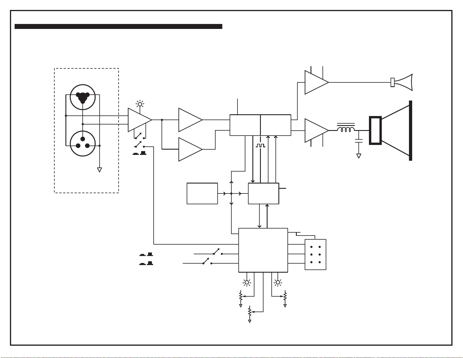
E10P Block Diagram
DESIGNED & MANUFA CTURED BY YORKVILLE SOUND
INPUT
1/4-inch / XLR
Combi-Jack
1
2
3
3
2
1
XLR
Amp / Chassis
Ground
CLIP
+
-
Mic / Line
0dB
-
30dB
12.288
MHZ CLK
3v3,5Vps
2 Ch A/D
CODEC
DSP
2 Ch D/A
SPI
±44V ±22V
MULTI-TIER
300W
3v3,1V8ps
3v3ps
50W
CLASS D
±80V
Horn Driver
10-inch
Woofer
LIVE / PLAYBACK
SUB IN/OUT
LIMIT
LEVEL
HOST PROCESSOR
WITH MEMORY
BASS
6-PIN BDM Connector
(for programming)
ANTI-FEEDBACK
TREBLE
BLOCK-DIAG-e10p-00-2v0.ai
Page 5
A
B
C
D
E
F
G
H
I
J
K
L
M
N
O
P
Q
1 1
INPUT
J3:A
+1/4
INPUT
2 2
3 3
4 4
5 5
6 6
7 7
XLR/1/4in
1/4in&XLR PCB MT VERT COMBO
J3:B
INPUT
XLR/1/4in
3416
LINK OUTPUT
J4
3453
R
T
S
100N
25V
100N
25V
IGND
+15V
C45
C52
-15V
18AWG
W32
G/Y
100N
25V
100N
25V
NET00030
MIC IN/OUT SWITC H
S4 is not stuffed
on M1496.
+15V
C48
+15V
100N
C53
25V
C54
SIGNAL_GND
COM
NC
LATCHING
S4:C
3440
COM
NC
LATCHING
S4:B
3440
W125
R58
W125
1K800
0805
DOWNUP
DOWNUP
R14
18K0
0805
R18
W125
18K0
0805
NO
NO
CLIP
LD4 RED
5906 for M1311
6405 for M1496
1N
50V
1N
50V
C11
C12
100N
25V
R13
W125
1K00
0805
SIGNAL_GND
R27
W125
1K00
0805
C71
D4
CDSF4148
D5
CDSF4148
MMBTA14LT1
Q6
7701
SMT
SIGNAL_GND
3
2
C13
R15
W125
10K00
+
-
C14
50V270P
0805
R19
W125
10K00
0805
50V270P
R59
W125
1M
0805
SIGNAL_GND
SIGNAL_GND
U4:A
1
NE5532D
R60
274K
1/8W
0805
R22
1K800
W125
R23
330R0
0805
W125
ANALOG_GND
C15
R20
W125
1K800
25V33U
10V0
D2 0W2
SIGNAL_GND
AINR+
R28
W125
30K00
6
5
-
+
10V0
D10W2
NE5532D
7
U4:B
R29
1K800
W125
R30
330R0
0805
W125
ANALOG_GND
C17
AK4620A CODEC
OVFR
15
C61
16
N.C.
CHECK +/-
AOUTR-
AOUTR+
AOUTL-
AOUTL+
OVFL
ANALOG_GND
U3:C
R2
W125
4K7
0805
R1
W125
4K7
0805
__4N7
50V
1/8W
200R
C1
1/8W
200R
W125
4K7
29
30
27
28
C2
25V100N
+15V
8
V+
V-
4
-15V
C3
25V100N
R3
W125
680P NOT NP0
4K7
0805
R5
0805
R6
0805
R4
0805
C4
2
3
50V680P
-
+
C5
NE5532D
1
U3:A
HORN OUTPUT
50V680P
SIGNAL_GND
U2:A
VREF
VCOM
6
+5V
8
AK4620A
Analogue Section
AGND
VA
7888
7
C62
6V3 100U
N.C.
25V100N
4
N.C.
N.C.
5
2
3
C64
AINL+
AINL-/NC
AINR+
AINR-/NC
1
25V10U
AINL+
25V33U
100N
C60
25V
ANALOG_GND
26 PIN
FEMALE
HEADER
TO
POWER
AMPS
1
W6:A26
3
W6:C26
25V 10U
C10
+15V
8 8
PARTS REFERENCE TABLE
9 9
REF DES
P3
P4
P5
10 10
S4
LD2
LD3
LD4
X1
11 11
A
B
C
X2
D
M1311
(E10P)
4388
4388
4388
3440
5907
5908
5906
4599
DNS
E
F
M1496
(PSA1)
DNS
DNS
4459
DNS
6400
6408
6405
DNS
4599
M1311 / M1496 - PCB _DATABASE _H ISTORY
MODEL(S):-
DA TE DESCRIPTION OF CHANGE
#
1
17-APR-201 1
2
16-JUN-2011 PC82xx: XH conn DS pads, add PCB title. GG
3
31-OCT-2011
4
5
25-NOV-2011
6
11-JAN -2012 . PC8361: CONSOLIDATED SMT RESISTORS. - ML
7
06-MAR_2012 V06 PC8385: Replace L56 #7896 with #8108 GG
8
D
9
10
D
11
D
12
D
13
D
G
E10P/PSA1
VER#
V04 DERIVED FROM M1311V03
.
PC8322: CHANGED W7 & W8 to XH CONN. - ML
.
.
PC8318: UPDT YS#7896 - CHANGED 'C56' to 'L56' - ML
V05 FORCE UPDATED SMT PARTS - FIXED LAYOUT. - ML
. Add SCORE lines on the sides. GG
.12-JUL-2012 PC8458 - Changed P5 from 4435 to 4459 for PSA1. - ML
V
N
V
N
V
N
V
N
H
I
J
K
L
25V 10U
-15V
C8
M
R9
W125
4K7
0805
1/8W
__4N7
50V
N
200R
C6
1/8W
200R
1/8W
15K0
8
V+
U4:C
V-
4
R7
W125
4K7
0805
R12
0805
R10
1/8W
15K0
0805
680P NOT NP0
C7
50V680P
6
-
5
+
NE5532D
7
U3:B
9
W6:I26
WOOFER OUTPUT
R8
0805
R11
0805
Product
INPUT/DS P
Date: Rev: YsTy pe:.
Filename:
C9
50V680P
WOOFER GND
10
W6:J26
CONNECTED THRU AMP
E10P(M1311) / PSA1(M1496)
M1311
PCB# Sheet 41
Thu Jul 12, 2012
X8019V06SCH.sch2006
O
M1496
V06
P
of
Q
Page 6
A
1 1
+3V3
R46
330R0
0805
W125
2 2
3 3
LD3
GRN
5908 for M1311
POWER
6408 for M1496
DIG_GND
384kHz
4 4
POWER
50V47P
R37
W125
47R
0805
ANALOG_GND
PS_GND
5 5
C20
+15V
6 6
7 7
LOW VOLTAGE
SUPPLY
8 8
DNS
Q3
LM317S
IN
REF/ADJ
7887
100NDNS
C25
25V
9 9
DNS
10 10
ANALOG_GND
These parts are not inserted.
11 11
A
DIG_GND
100U
25V
OUT
TO263
R38
1K800
W125
+3V3
C23
100N
C65
25V
+3V3COD
7
B
1/8W
2K32
VIN
B
+3V3
DIG_GND
R33
0805
U6
7890
R39
1K00
DNS
W125
100N
C86
100N
C66
25V
2SS3
LM2671M-ADJ
ON/OFF
5
+3V3COD
25V
18
17
9
23
22
19
C
100N
C85
25V
ANALOG_GND
CKS1
CKS0
AK4620A CODEC
P/S
ADMODE
DEM0
DIF
VDDINT TO DSP
4
FB
SYNC
VSW
GND
6
100NDNS
C19
25V
C
+3V3COD
1
CB
8
25V10U
C70
7888
Digital Section
AK4620A
U2:B
C22
MBRA340T3
{Voltage}
PS_GND
DNS
Q1
LM317S
IN
REF/ADJ
7887
TO263
R34
2K32
DNS
1/8W
0805
+3V3
4
OSCILLATOR
2
DIG_GND
+3V3COD
24
26
25
VT
DGND
50V_10N
D6
OUT
Vdd
GND
VD
D
Q5
7894
OUT
E/D
3
1
CWX823-12.288
ANALOG_GND
DFS0
20
MCLK
10
SDTI
14
SDT0
13
BICK
12
LRCK
11
PDN
21
+3V3
L56 8108
120UH
100N
25V
D
DNS
R32
330R0
0805
W125
+3V3COD
R68
10R
1206
IN
7887
C21
PS_GND
PS_GND
E
ANALOG_GND
W250
680U
C24
6V3
Q2
LM317S
REF/ADJ
TO263
R35
1K00
W125
+5V
100N
C55
25V
E
OUT
8200NH
7941
15P
16V
L3
C57
R45
10K00
0805
ANALOG_GND
+15V
R55
1K800
0805
W125
100N
C72
25V
DIG_GND
W125
R36
330R0
0805
W125
21
F
+5V
R63
1K800
0805
W125
F
+3V3
R47
1/8W
200R
0805
R49
W250
10R
0805
5V1
D7
{Voltage}
0W35
R51
W250
10R
0805
VCC
R50
W250
10R
0805
N.C.
N.C.
G
3N3
C82
25V
R48
W250
10R
0805
1
6W2:A
3
6W2:C
5
6W2:E
BDM_PORT
14
VCC
GND
U1:C7907
7
G
+3V3
R66
475R0
1/8W
0805
100N
C83
25V
47U
C84
16V
DIG_GND
R43
4K7
0805
W125
ANALOG_GND
47U
16V
DIG_GND
2
6W2:B
DIG_GND
4
6W2:D
+3V3
6
6W2:F
96kHz TO WOOF ER AMP
11
W6:K 26
PART OF 26 PIN
FEMALE MOLEX
H
C77
N.C.
N.C.
N.C.
N.C.
H
100N
C78
25V
40
41
46
45
44
43
BCLK
LR_CLK
VCC
CM
FILTD
CLK
OSC
DIG_GND
C73
N.C.
32
MCLKI
VOUT0
DAC
VOUT1
VOUT2
DAC
VOUT3
8-CH
Digital
Output
MP11
19
Bclk_OUT
LR_CLK_OUT
100N
25V
100N
25V
DIG_GND
I
16V
47U
35
31
OSCO
PLL_LF
GPIO
Input/Output Matrix
MP614MP7
MP10
15
16
N.C.
DIG_GND
+3V3
C67
DIG_GND
1U
C68
50V
I
100N
C74
25V
42
39
33
AGND37AGND
PGND
7905
N.C.
C69
8
9
AGND
MODE138MODE0
PLL
ADAU1701
28/56-BIT, 50 MHz
AUDIO PROCESSOR CORE
40 ms DELAY MEMORY
8-Bit
Aux
ADC
MP9
MP327MP8
MP5
MP2
26
28
29
N.C.
N.C.
Bclk_IN
N.C.
1
RESET
11
IRQ
10-Bit ADC
40
DDAD
41
SSAD
30
VREFH
31
VREFL
17
VDD
16
VSS
13
2CLR
2CLK
2Q
2D
2Q
2PRE
7907U1:B
10
J
100N
C75
25V
36
1
48
AVDD
AVDD
8-CH
Digital
Input
MP08MP4
MP1
9
11
10
N.C.
LR_CLK_IN
MC9S08GT60
8-BITMicrocontroller
11
12
J
18
IOVDD
7906
100N
25V
25
DGND
Control
Interface
and
Selfboot
SCL/CCLK
23
C76
DGND
12
DVDD
CLATCH/WP22SDA/COUT
ADDR1/CDATA/WB
21
U7
6
5
K
+1V8 SUPPLY
34
13
17
24
DVDD
PVDD
VDRIVE
1.8V Reg
ADC1
Stereo ADC
ADC0
ADC_RES
Reset/
Mode
Select
RESETB6SELFBOOT
ADDR0
7
20
PTA7/KBI1P7
PTA6/KBI1P6
P
PTA5/KBI1P5
O
PTA4/KBI1P4
R
PTA3/KBI1P3
T
PTA2/KBI1P2
A
PTA1/KBI1P1
PTA0/KBI1P0
PTB7/AD1P7
PTB6/AD1P6
P
PTB5/AD1P5
O
R
PTB4/AD1P4
T
PTB3/AD1P3
PTB2/AD1P2
B
PTB1/AD1P1
PTB0/AD1P0
P
O
R
PTC3/SCL1
T
PTC2/SDA1
PTC1/RxD2
C
PTC0/TxD2
P
PTD4/TPM2CH1
O
PTD3/TPM2CH0
R
PTD1/TPM1CH1
T
PTD0/TPM1CH0
D
PTE5/SPSCK1
P
PTE4/MOSI1
O
PTE3/MISO1
R
T
PTE1/RxD1
E
PTE0/TxD1
P
PTG2/EXTAL
O
PTG1/XTAL
R
PTG0/BKGD/MS
T
G
1
1CLR
1CLK
1Q
1Q
1PRE
3
1D
2
7907U1:A
4
K
+3V3
DIG_GND
FILTA
RSVD
5
PTC6
PTC5
PTC4
PTE2/SS1
L
R64
W125
1K00
0805
U8
2
N.C.
4
N.C.
3
47
N.C.
30
39
38
37
N.C.
36
N.C.
35
34
33
32
29
28
27
N.C.
26
25
N.C.
24
23
22
8
7
6
5
N.C.
4
N.C.
3
N.C.
2
N.C.
21
N.C.
20
N.C.
19
N.C.
18
15
14
13
12
10
N.C.
9
N.C.
44
43
N.C.
42
DIG_GND
R62
W250
10R
0805
L
R65
18K2
0.1W
0805
M
SOT23
7805
Q8
MMBT3906LT1
+3V3
47U
16V
S4 is YS#3440 on M131 1.
S4 is not stuffed on M1496.
NC
COM
NC
COM
NO
DIG_GND
NO
S3:A
3522
LATCHING
DIG_GND
UP
DOWN
ANTI-FEEDBACK
DIG_GND
S2:A
3439
MOMENTARY
TO PIN 6 OF W12
CDSF4148
D3
R42
100R
1/8W
0805
M
NC
UP
S2 IS NOT
STUFFED.
S8:A
3522
LATCHING
UPDOWN
R40
475R0
1/8W
0805
NC
COM
NO
DIG_GND
COM
LD2
YEL
NO
C80
UP
DOWN
DOWN
N.C.
+3V3
N
100N
C79
25V
DIG_GND
S4:A
LATCHING
DIG_GND
+3V3
100N
C26
25V
DIG_GND
LIMIT
6400 for M1496
5907 for M1311
N
100N
25V
O
C81
P
SWITCH FUNCTIONS
+80V
S3
S4
S8
E10P
LIVE / PLA YBACK
MIC / LINE
SUB IN / O UT
+44V
PSA1
LOW FREQ CUT
NOT USED
HIGH FREQ BOOST
POT FUNCTIONS
R52
475K
1/8W
0805
R44
4K7
0805
W125
100N
C27
25V
Product
DSP
Date: Rev: YsTy pe:.
Filename:
R53
475K
1/8W
0805
P3 GAIN
R54
P4 BASS
4K7
0805
W125
P5
DIG_GND
INPUT CONTROLS
MAKE SURE POTS AND SWITCHES ARE CORRECT ORIENTATION
TB
100K
B LIN
4388
P3
M
LD1 IS NOT
STUFFED.
R56
33K
0805
W125
MMBTA14LT1
SMT
100N
C29
25V
DIG_GND
E10P(M1311) / PSA1(M1496)
Thu Jul 12, 2012
X8019V06SCH.sch2006
O
E10P
TREBLE
TB
100K
B LIN
4388
P4
M
100N
C30
25V
+15V
LD1
BLU
DNS
R41
2K32
1/8W
0805
Q7
7701
PCB# Sheet 42
DIG_GND
ANTI FEEDBACK
M1311
M1496
V06
P
NOT USED
NOT USED
100N
25V
PSA1
LEVEL
100K
B LIN
4388
P5
C31
Q
+3V3
TB
M
of
Q
Page 7

A
1 1
POWER SUPPLY
2 2
IEC_RECT
DPDT Switch
S9
3 3
AC_GND
R187
IGND
1K8
PS_GND
6561
S6:A
4 4
5 5
MAINS VOLT AGE
6 6
7 7
8 8
9 9
10 10
11 11
SELECTOR
(NOT STUFFED)
A
B
12
34
TO CHASSIS GROUND
G/Y
W16
R57
22R
1/4W
1206
1W00
100N
C40
100V
S6:B
6561
LVGND
B
G/Y
W33
Copper
Tie Here
LVGND
FUSE
F1
FAST BLOW
100N
C102
250V
4N7
C112
250V
BLK
W21
18AWG
BLK
W22
18AWG
BLK
W23
18AWG
BLK
W24
18AWG
BLK
W25
18AWG
Tie-net Name
C
18AWG
BLK
W17
PS_GND
C
AC-WHT1
18AWG
WHT
W18
BLK
W26
18AWG
BLK
W27
18AWG
BLK
W28
18AWG
BLK
W29
18AWG
BLK
W31
18AWG
1300UH
FUSE F1
N.A.
C.E.
L56492
D
D
C106
680N
250V
E10P
#2403 T2A
E
E
PSA1
#2479 F5A#2475 T3.15A
#2482 F3.15A
ORANGE
BLK
BLU
BRN
BLK/YEL
WHT
F
PIN 1
FEMALE CONNECTOR
VIEWED FROM WIRE SIDE
E10P: CH1342U
PSA1: CH1341U
ORN
BLK
BLU
BRN
BLK/YEL
WHT
F
10U
25V
W125
R25
33K
0805
G
C28
G
VIO_
GRY_
RED_
YEL
RED
GRY
VIO
MBS4992
Q10:A
5190
TO92
H
PCB MALE CONNECTORS
1
7915
D2PAK
2
3
4
5
6
NC
D63
S3D
S3D
D62
Q4
MT1 MT2
G
-80V
+80V
R26
W250
10R
1206
WOOFERGND
BLK
BRN
ORANGE
BLU
WHT
NC
T810-600G-TR
H
I
MALE 9 PIN CONNECTOR FOR
TRANSFORMER SECONDARYS
W30:A6BLK/YEL
W30:B6
W30:C6
W30:D6
W30:E6
W30:F6
PIN 1
FEMALE CONNECTOR
VIEWED FROM WIRE SIDE
W4:D 0
W4:C 0
W4:B 0
W4:A 0
I
4
3
2
1
W3:A 9
W3:G 9
W3:C 9
W3:E 9
W3:F 9
W3:H 9
__2U2
C50
100V
W3:B 9
W3:D 9
W3:I 9
J
1
7
3
2
5
6
4
8
9
4UH
_W1
__2U2
C49
100V
WOOFERGND
J
K
L
M
N
O
MUTE ON/OFF
0805
10K00
W125
R31
LVGND
R21
W125
1M
0805
+44V
2200U
63V
2200U
63V
-44V
C104
C115
C18
25V
4U7
D48
S3D
D53
S3D
D59
S3D
D61
S3D
R24
1/8W
2K32
0805
2200U
50V
2200U
50V
C105
C111
+24V
-24V
PS_GND
18V018V0
D8 0W2
C16
D54
D60
50V
1U
D51
S3D
S3D
D57
S3D
S3D
VIO_
GRY_
RED_
VIO
RED
GRY
D49
CDSF4148
7895
R16
7A
2487
R98
T7.0
7895
CDSF4148
2487
R61
T7.0
R17
7A
SILENT
D50
D52
S3D
D55
S3D
D56
S3D
D58
S3D
NC
ALL DIODES S3D 200V 3A0 DIO D214 SMT
NC
PUT PADS UNDER HIGH CURRENT AND ALTERNATE
16
L13759
L2 6562
2N2
C118
50V
R220
10R
1206
W250
HORNGND
4
3
2
1
192UH
SMALLLER COIL
CHANGE PART
K
W6:P26
15
W6:O26
PART OF 26 PIN
2
FEMALE MOLEX
W6:B26
S5
HORN
SP1
OUTPUT
WOOFER
26
W6:Z26
25
W6:Y26
PART OF 26 PIN
22
21
FEMALE MOLEX
W6:V26
W6:U26
Product
E10P(M1311) / PSA1(M1496)
POWER SUPPLY
Date: Rev: YsTy pe:.
Thu Jul 12, 2012
L
M
N
Filename:
X8019V06SCH.sch2006
O
P
SOT-23
7837
Q9
MMBT5401
-20V UNMUTE
12
4700U
100V
C63:A
PS_GND
4700U
C123:A
100V
MUTE
+44V
+24V
LVGND
+15V
-15V
-80V
24
23
13
14
6
7
8
4
5
17
18
19
20
+80V
26 PIN
FEMALE
HEADER
TO
POWER
AMPS
M1311
PCB# Sheet 43
M1496
V06
P
Q
W6:L26
W6:X26
W6:W26
W6:M26
W6:N26
W6:F26
W6:G26
W6:H26
W6:D26
W6:E26
W6:Q26-24V
W6:R26-44V
W6:S26
W6:T26
of
Q
Page 8

V
W12
1
2329
12
C23
X8019 V06
100N
47U
100N
100N
ADAU1701
7905
C78
C69
C68
100N
C9S08GT60
M
JTAG HEADER
DSP program
Header
C20
47P
7890
U6
DON'T MOVE ANYTHING
47U
C74
100N
C75
100N
C83
3N3
C82
475R0
R66
10R
10R
R49
R50
10R
10R
R51
R47
200R
L3
CWX823-12.288
8200NH
For BDM Port
426
4148
31
W2
C24
680U
R48
C64
100U
C61
R45
10K00
10U
Q5
5
+3V3COD
SUPPLY
C84 C73
C79
R65
C76
18K2
100N
MMBT3906LT1
47U
Q8
U8
C80
C81
100N
R64
1K00
100N
47U
1U
10R
D6
R40
D3
U7
C65
100N
R33
2K32
LM2671M-ADJ
MBRA340T3
C22
50V
7906
_10N
120UH
J
C77
475R0
100R
6
R42
100N
C67
R68
R37
47R
100U
L56
1
100N
C86
R62
R23
C15
10R
R43
4K7
15P
100N
100N
C48
2327
330R0330R0
C60
C62
AK4620A
CODEC
U2
C57
DIGITAL GROUND
(DIG_GND)
C66
100N
U1
C55
100N
LM317S
W13
6
R1
R30
33U
C17
C85
100N
7888
10U
C70
ANALOG GROUND
C72
SN74AC74DR
+5V
SUPPLY
R36
330R0
Q2
ANALOG
4K7
100N
ANALOG
100N
4K7
200R
R6
C8
10U
R7
C10
100N
1K800
R63
1K800
R35
1K00
7887
C3
C53
10U
C1
200R
R4
4K7
100N
7903
NE5532D
680P
C5
100N
C54
__4N7
C6
200R
R8
680P
C9
15K0
4K7
TOM'S GROUND
R54
475K
4K7
R53
4K7
475K
R44
R52
C21
100N
4K7
680P
R11
__4N7
C2
R5
R2
4K7
LOW VOLTAGE GROUND
(LVGND)
PSGND
D7
5V1
R55
R3
C4
680P
200R
15K0
R9
SIG GND
MUTE
+24V
HORN
OUTPUT
-44V
OUTPUT
HORN
GND
U3
R12
R10
C7
W6
HORN SIGNAL
C16
HORN
GND
-15V
-24V
+24V
26 PIN
LVGND
+15V
SIGNAL
96KHZ
+44V
-24V
-80V
W
OO
G
FE
ND
+
8
0V
6535
WOOFER OUTPUT
18V0
D8
18V0
1U
50V
R220
10R
TO SPEAKERS
R
C49
__2U2
__2U2
C50
C18
4U7
MMBT5401
1M
Q9
R21
1/2
V06
PSA1 - M1496
E10P - M1311
2N2
C118
3538
S3D
L2
C104
2200U
63V
C105
L1
3759
4UH
DON'T PUT
ANYTHING
ON TOP
LAYER
HERE
C28
W4
D62
10U
T
R
V
T
R
V
T
R
V
R26
10R
10K00
R31
2K32
R24
C115
2200U
T
R
V
R
2200U
50V
R
Q10
Q4
33K
R25
DON'T PUT
ANYTHING
ON TOP
LAYER
HERE
192UH
63V
T
V
2200U
T
V
C111
MBS4992
50V
7915
T810-600G-TR
S3D
D63
D50
D49
T
R
V
D57
S3D
4700U
100V
5910
T
T
R
V
T
R
V
R
V
T
R
V
C63
D54
S3D
S3D
D60
C123
T
R
5910
D56
V
S3D
T
R
V
4700U
100V
D58
D52 D55
S3D
S3D
S3D
S3D
D51
D61
S3D
D59
S3D
D48
S3D
1
CLIP
Q6
5906
5907
2 OZ. COPPER
BlankSize - 9200x7100
5908
MMBTA14LT1
C71
R58
100N
1K800
LD2 LD4
YEL RED
LIMITER
R46
330R0
...
---
LD3
GRN
POWER
P3
CLINCH
VCD
INSERT
ORIGIN
ORIGIN
BlankSize - 9200x7100
6
W15
3522
CR
NOR
NCR
CL
NCL
SUB IN/
SUB OUT
NOL
S8
D4
D5
= GROUND MERGE
3522
CR
NCR
S3
NOR
Alternate Alternate
CL
NCL
NOL
E10P - M1311
PSA1 - M1496
B LIN
4388
100K
X8019
12
2329 2327
33K
R56
2K32
1M274K
R41
R59
R60
MMBTA14LT1
1
Q7
100N 33U
R22
C29
S4
LIVE/
PLAYBACK
MIC / LINE
V06
2/2
P5
100N
C27
100K
100N
C31
B LIN
4388
V06
1K800
C14
270P
R14
18K0
R18
18K0
3440
M1311
M1496
P4
4388
100N
C26
1K800
R27
1K00
1N
C11
BASSGAIN TREBLE
C13
1N
R29
C12
270P
1K00
6
W14
R19
10K00
U4
7903
10K00
R15
R13
B LIN
NE5532D
100N
X1
X2
100K
R20
1K800
C52
W7
R28
C45
100N
1
2337
4
100N 30K00
10V0
10V0
C30
D53
7A
R17
R61
T7.0
T7.0
2
D1
D2
3453
1
2337
1
4
W8
3416
T
5
J4
.
3
BLK
W32
W21
BLK
W22
BLK
W23
J3
BLK
W24
M1311 / M1496
V06
BLK
W25
REPLACE R16 AND R17 WITH
AXIAL FUSE #2487 T7A
BLK
W26
BLK
W27
BLK
W28
BLK
W29
W31
BLK
DNS
DNS
INSERT ONLY IF R17
1K8
G/Y
R187
W16
C106
V
T
R
250V
680N
V
T
R
C112
OR R16 ARE OPEN
G/Y
5266
6451
V
T
R
R
4N7
R
T
V
T
V
C40
22R 100N 7A
R57
1
W30
4147
T
R
V
T
R
V
T
R
V
GND
6
W33
R98
3
9
L5
R16
4145
T
R
1300UH
6492
V
T
R
S3D
1
XFMR
W3
C102
W17
V
BLKWHT
5242
V
T
T
R
V
R
250V
100N
W18
T
R
V
V
T
R
T
T
R
V
T
R
V
R
V
V
T
R
V
T
R
T
R
V
250V
M1311
06
SEE PRODUCTION NOTES
E10P
Page 9

SEE LAYOUT DIAGRAM
M1311
1. B.A. STUFF X FIRST.
V06
1
PRODUCTION NOTES
2. B.A. ADD RTV BETWEEN C106, C112 AND W30 THE POWER CONNECTOR
3. B.A. ADD RTV UNDER J3 XLR.
4. B.A. DO NOT STUFF S2 AND LD1.
5. B.A. ADD YS#3822 1.25" HEATSHRINK AROUND J3
6. B.A. DO NOT STUFF S6
7. B.A. FOR N.A. BOARDS ADD 18AWG JUMPER FROM W26 TO W27 AND FROM W29 TO W31
8. B.A. FOR CE BOARDS ADD 18AWG JUMPER FROM W27 TO W31
9. PCBSA: DO NOT BREAK OUT BOARD BEFORE TESTING
X8019 REFERENCE TABLE
REF DES
P3
P4
P5
S4
LD2
LD3
LD4
X1
X2
M1311 E10P
USED ON
4388
4388
4388
3440
5907
5908
5906
4599
DNS
M1496
USED ON
DNS
DNS
4459
DNS
6400
6408
6405
DNS
4599
PSA1
SEE LAYOUT DOCUMENTATION
Page 10

SEE PRODUCTION NOTES
MODEL(S):-
#
1
2
3
4
5
6
7
DATE
17-APR-2011 V04 DERIVED FROM M1311V03. PC 8242
16-JUN-2011 PC82xx: XH conn DS pads, add PCB title. GG.
31-OCT-2011
.
11-JAN-2012
06-MAR_2012
M1311
E10P
VER# DESCRIPTION OF CHANGE
V05
.
V05 FORCE UPDATED SMT PARTS - FIXED LAYOUT. - ML25-NOV-2011
.
V06
PCB_DATABASE_HISTORY
PC8322: CHANGED W7 & W8 TO XH CONN. - ML
PC8318: UPDT YS#7896 - CHANGED 'C56' to 'L56' - ML
PC8361: CONSOLIDATED SMT RESISTORS. - ML
PC8385: Replace L56 #7896 with #8108 GG
8
9
10
11
12
13
D
D
D
DVN
D
.
V
V
V
Add SCORE lines on the sides GG
Created new Design Views for clearer PDFs - ML.26-APR-2012
N
N
N
Page 11

1
6
2329
12
W12
100U
C23
47U
C80
47R
R37
R42
C77
C81
475R0
100R
100N
R68
C79
18K2
100N
MMBT3906LT1
Q8
R64
100N
1K00
100N
47U
C78
R40
D3
C67
U7
C65
100N
10R
R33
2K2
D6
LM2671M-ADJ
MBRA340T3
U6
C22
C56
C84
47U
R65
C76
100N
ADAU1701
U8
7905
C68
50V1U100N
C69
7906
0
S
9
C
M
C20
47P
7890
_10N
DON'T MOVE ANYTHING
C73
C74
100N
R48
9
4
R
R50
2
T3
8G
JTAG HEADER
DSP program
Header
C24
680U
115uH
C64
47U
C75
C83
C82
R66
C61
200R
R47
L3
CWX823-12.288
8200NH
426
3
W2
100U
R45
10K
10U
Q5
+3V3COD
SUPPLY
100N
100N
3N3
475R0
10R
10R
10R
10R
R51
For BDM Port
4148
15
1
100N
R62
C86
10R
100N
R23
C15
R43
4K7
15P
C48
2327
33U
100N
C60
100N
C62
CODEC
C57
DIGITAL GROUND
(DIG_GND)
C66
100N
C55
100N
Q2
330R0330R0
R30
7888
AK4620A
U2
C70
ANALOG GROUND
SN74AC74DR
R36
LM317S
W13
6
33U
U1
+5V
SUPPLY
ANALOG
R1
4K7
100N
ANALOG
100N 4K7
C3
4K7 100N
200R 680P
R6
C17
C8
C85
100N
10U
C72
100N
R63
1K800
R35
1K00330R0
7887
__4N7
C2
R5
200R
R4
C53
R2
C5
C54
100N
C6
10U
R7
1K800
__4N7
200R
4K7
C9
10U
C10
R9
4K7
LOW VOLTAGE GROUND
(LVGND)
TOM'S GROUND
PSGND
D7
5V1
R54
4K7
R55
4K7
R44
C21
100N
PART OUTLINE
C1
R3
4K7
OUTPUT
HORN
GND
U3
C7
W6
HORN SIGNAL
WOOFER OUTPUT
7903
R8
680P
15K0
680P
C4
NE5532D
R12
200R
R11
475K
R53
475K
R52
680P
15K0
R10
SIG GND
MUTE
+24V
HORN
OUTPUT
-44V
+
80V
C16
HORN
GND
26 PIN
LVGND
+15V
SIGNAL
96KHZ
+44V
-24V
-80V
W
OO
G
FE
N
D
18V0
18V0
D8
1U
50V
-15V
-24V
+24V
D.N.S.
R220
2N2
TO SPEAKERS
R
C49
__2U2
__2U2
C50
C18
4U7
MMBT5401
1M
R21
E10P
M1311
V03
1/2
DNS
C118
S3D
L2
Q9
3538
C104
2200U
63V
C105
L1
4UH
DON'T PUT
ANYTHING
ON TOP
LAYER
HERE
W4
D62
C28
10U
R
R
V03M1311
T
R
T
V
T
V
3759
R26
V
Q10
10R
10K
R31
2K2
R24
C115
2200U
63V
T
R
V
R
2200U
50V
T
R
MBS4992
Q4
33K
R25
DON'T PUT
ANYTHING
ON TOP
LAYER
HERE
192
U
T
V
V
H
2200U
50V
C111
7915
S3D
D63
D50
Tie Here
Copper
D49
T
R
V
C63
4700U
5910
100V
T
T
R
V
T
R
V
MAC4DSM
R
V
T
C123
R
V
T
R
V
T
R
V
4700U
100V
S3D
D61
S3D
S3D
S3D
S3D
D57
D60
D54
D51
YORKVILLE E10P M1311 V3.00
5910
D59
S3D
D56
S3D
D58
S3D
S3D
D55D52
S3D
D48
S3D
CLIP
MMBTA14LT1
-
+
2 OZ. COPPER
LD4
5906
LD2LD3
59075908
RED
1K5
R58
-
+
YEL
R46
270R
-
+
YORKVILLE E10P M1311 V3.00
CLINCH
ORIGIN
1
W15
C71
100N
D5
LIMITER
POWER
GRN
GAIN
CONTROL
INSERT
ORIGIN
SUB IN/
Q6
D4
4388
SHORT AXIS
6
33K
NOR
NOL
WHT
R60 R59
R56
R41
DNS
274K 1M
2K32
6554
BLU
2329
3522
S8
NCR
Alternate
CL CR
NCL
SUB OUT
= GROUND MERGE
3522
S3
NOR
NCR
Alternate
CL CR
NCL
NOL
WHT
LIVE/
PLAYBACK
B LIN
100K
Function
P3
C27
100K
100N
LONG AXIS
P5
4388
Top Assy
12
Q7
S2
BLU
LD1
S4
3440
MIC IN/
MIC OUT
B LIN
100N
MMBTA14LT1
NCR
DNS
CL CR
NCL
MOMENTARY
3439
Function
1
R22
C29
1K800
NOR
NOL
C14
270P
R14
WHT
TREBLE
CONTROL
100N
100N
C26
C31
M1311
2327
1K800
1K00
17K80
17K80
R18
100K
P4
4388
1N
C13
1N
C11
R29
R27
C12
270P
1K00
R13
V03
6
10K00
R19
U4
NE5532D
7903
10K00
R15
B LIN
2/2
W14
R20
100N
1K800
C45
R28
C52
100N
5989
BASS
CONTROL
Function
100N 30K00
10V0
1
1
C30
D1
W7
D2
10V0
3416 3453
W8
R61
R17
REPLACE R16 AND R17 WITH
AXIAL FUSE #2487 T7A
3
1 2
BLK
BLK
BLK
W26
W27
W28
1
5989
J4
BLK
1
1
J3
POINT SWITCH
W21
THIS WAY
6
S
BLK
W22
BLK
W23
R
D
R
DNS
65
E10P
V
M1311
V03
61
BLK
W24
BLK
W25
W31
BLK
BLK
W29
T
5
D
P
3T
S
C
C40
1K8
R57
22R 7A100N
W30
4147
T
R
V
T
R
V
T
R
V
C112
GROUND
6
W33
G/Y
T7.0
R187
W16
C106
T
R
250V
680N
T
R
DNS
V
V
R98
R16
T7.0
DNS
INSERT ONLY IF R17
OR R16 ARE OPEN
G/Y
L5
5266
T
R
V
6451
4N7
V
T
R
T
R
V
7A
3
1300UH
6492
V
T
R
V
T
R
D53
S3D
1
W3
4145
9
C102
W17
BLK
5242
V
T
T
R
V
R
250V
100N
WHT
W18
250V
V03Pcb Mech M1311
Page 12

A
1 1
B
C
D
E
F
G
H
I
J
K
L
M
N
O
P
Q
WOOFER
325W NON INVERTING CLASS D AMPLIFIER
C2
50V22P
R21
W125
2 2
3 3
R5
W125
560R
0805
AUDIO IN
4 4
96KHz
5 5
6 6
7 7
C1
25V100N
EXTRA
8 8
R1
W125
470R
0805
MC33078D
U1:A
R23
150K
560R
0805
R13
1/8W
1M0
1206
C4
50V10N
R9
W125
10K
0805
C3
50V__4N7
8
V+
U1:C
V-
4
0805
W125
15V0
D4
0W2
W125
MC33078D
U2:B
MC33078D
U1:B
DPAK3
MJD243T4G
R7
47R
0805
R99
W125
47R
0805
7844
R20
100R
0805
W250
Q3
__1U
100N
C7
100V
C8
25V
7851
LM311
U5
R15
W125
1M
0805
R98
W125
10K
0805
CDSU4148
D2
47P
C6
50V
MMBT5401
SOT-23
CDSU4148
D3
R22
1K5
0805
R4
W125
100K
0805
W125
W125
Q1
7837
R11
10K
0805
W125
W125
R18
4K7
0805
R16
2K2
0805
SOT-23
MMBT3904
R10
1K5
0805
W125
MMBT5401
Q2
7837
R24
100K
0805
W125
D5
CDSU4148
SOT-23
470P
50V
C35
Q4
7838
R26
33K
MC33078D
U3:B
7835
U3:A
1U
25V
IRS20124S
7835
C34
R25
10K
0805
W125
C37
1N
50V
R28
4K7
0805
W125
R27
270R
0805
W125
R31
W125
10K
0805
R29
39K
1/8W
0805
0805
W125
U2:A
R38
10R
0805
U2:C
R32
1/8W
3K9
0805
W250
1U
25V
8
V+
V-
4
D6
MURA240T3
C12
10N
50V
R12
1K00
0805
W125
C5
W063
47K
C19
7833
R33
W125
20K
0805
470P
50V
470P
50V
R35
W125
20K
0805
R37
3K9
1/8W
0805
R79
10K
0805
W125
50V_10N
R75
10K
0805
W125
R2
C10
C11
R14
1M
0805
W125
100N
100V
R34
W125
20K
0805
R36
W125
20K
0805
R39
1/4W
22R
1206
1206
10R
W250
R8
D8
MBRA340T3
R41
100K
0805
W125
R40
1/4W
22R
1206
R30
W250
10R
1206
R42
100K
0805
W125
C9
D9
MBRA340T3
D
IRFS4227PBF
S
D
S
Q5
7968
D2PAK
IRFS4227PBF
Q6
7968
D2PAK
C13
200V
2U2
2U2
200V
C14
2U2
200V
C15
2U2
100V
C17
2U2
100V
C16
G
G
Q7
9 9
100N
C20
25V
100N
10 10
11 11
C22
25V
100N
C21
25V
A
B
100N
100V
C33
C
MC7815BDTG
OUTIN
GND
7846
DPAK3
7847
DPAK3
GND
OUTIN
MC79M15CDTG
Q8
D
100N
25V
C18
M1495 - PCB DATABASE HISTORY
MODEL(S):-
DA TE DESCRIPTION OF CHANGE
#
OCT 5th 2010 V01 FIRST PRODUCTION. DERIVED FROM M1310
1
28-JUN-2011
2
3
4
D
D
5
D
6
7
D
8
D
9
D
10
D
11
D
12
D
13
D
E
F
G
H
E10P / PSA1
VER#
PC8222: Panelize and fiducials GG
V02
PC8428 - Moved the fids further into the panel. - MLV0303-MAY-2012
V
N
N
V
N
V
V
N
N
V
N
V
V
N
N
V
N
V
V
N
I
J
Product
WOOFER AMP
Date: Rev: YsTyp e:YsType
K
L
M
N
Filename:
E10P / PSA1
Thu May 03, 2012
M1495V03SCH.sch2006
O
PCB# Sheet 31
M1495
V03
P
of
Q
Page 13

A
1 1
B
C
D
E
F
G
H
I
J
K
L
M
N
O
P
Q
26 PIN MALE
2 2
HEADER
26
W1:Z26
3 3
4 4
5 5
6 6
7 7
8 8
9 9
25
W1:Y26
24
W1:X26
23
W1:W26
22
W1:V26
21
W1:U26
20
W1:T26
19
W1:S26
18
W1:R26
17
W1:Q26
16
W1:P26
15
W1:O26
14
W1:N26
13
W1:M26
12
W1:L26
11
W1:K26
10
W1:J26
9
W1:I26
8
W1:H26
7
W1:G26
6
W1:F26
5
W1:E26
4
W1:D26
3
W1:C26
2
W1:B26
1
W1:A26
AUDIO IN
R17
W125
1M
0805
0W2
D15
18V0
R47
W125
1K5
0805
MMBF4391LT1
Q14
7806
SOT-23
W125
R48
33K
0805
C23
25V4U7
C24
MMBT5401
SOT-23
R44
4K7
0805
W125
R54
270R
0805
W125
MMBT5401
R6
W063
10K
MMBT5401
SOT-23
7926
R52
W125
1K5
R46
470R
0805
W125
10U
25V
0805
C25
R49
W125
10K
0805
C26
R19
10K
0805
W125
R45
D16
CMPD914
R50
W125
1K5
0805
Q17
7837
1/8W
100R
0805
50V4N7
Q9
7837
SOT-23
R53
560R
0805
W125
50V_10P
100P
50V
R51
1K5
0805
W125
30 WATT HORN POWER AMP
C36
Q18
7837
C27
100N
25V
MJD243T4G
Q13
7844
DPAK3
R43
47R
0805
W125
R55
W500
2K2
2010
C28
47U
35V
C29
50V
12V0
D12
0W2
1U
12V0
D17
0W2
1U
50V
R56
W500
2K2
2010
C30
R60
W250
100R
0805
0W2
CMPD914
D19
CMPD914
D18
CMPD914
D20
CMPD914
D21
R58
W500
2K2
2010
D14
10V0
R57
W250
100R
0805
CMPD914
D23
W500
R59
2K2
2010
D22
CMPD914
MJD243T4G
Q12
7844
DPAK3
R61
470R
0805
W125
R62
470R
0805
W125
MJD253T4G
Q19
7845
DPAK3
15V0
D24
0W2
15V0
D10
0W2
D
IRF530NS
R65
0R27
1/4W
1206
R63
0R27
1/4W
1206
S
MJB41C
Q15
7842
D2PAK
MJB42C
Q20
7843
D2PAK
S
D
Q10
7840
D2PAK
IRF9530NS
Q11
7839
D2PAK
R64
0R27
1/4W
1206
R66
0R27
1/4W
1206
MJB41C
Q21
7842
D2PAK
MJB42C
Q16
7843
D2PAK
MURA240T3
R67
1.50
0W8
D26
MURA240T3
D25
100N
100V
C32
100N
100V
C31
G
G
10 10
Product
11 11
HORN AMP
Date: Rev: YsTyp e:YsType
A
B
C
D
E
F
G
H
I
J
K
L
M
N
Filename:
E10P / PSA1
Thu May 03, 2012
M1495V03SCH.sch2006
O
PCB# Sheet 32
M1495
V03
P
of
Q
Page 14

HAND PLACE W1 USING JIG
BEFORE THE REFLOW OVEN.
WOOFER AMPLIFIER
D6
R39
D8
22R
R8
R75
10K
10K
R79
R25
7838
7893
10K
R5
C12
10N
4K7
Q4
R85
C3
560R
R86
C5
R12
D9
4N7
C21
1U
R41
1K00
R28
R27
470R
U1
0R
MC33078D
0R
100N
U3
270R
Q6
R89
7893
10R
1U
7837
0R
R14
C9
0R
Q2
0R
R32
100N 1M
47K
R2
R82
560R
22P
3K9
7848
U4
39K
R24
0R
R33
R88
R38
7836
TLC555
R31
10K
100K
100K
R4
R13
1M0
7817
MC33078D
U2
C2
0R
C19
10N
R29
C37
1N
33K
R15
R99
C22
R35
20K
C10 C11
10R
0R
R78
10K
470P
1K5
R10
C35
R26
0R
1M
47R
R9
R87
0R
100N
20K
3K9
R37
470P 470P
20K
R34
100N
C8
R20
150K
R23
D5
R72
0R
7837
2K2
R16
10K
R98
47R
R7
BlankSize - 6275x11800
7851
LM311
U5
MJD243T4G
100R
D4
7831
7768
10K
R11
Q1
7844
C6
7768
D3
1K5 47P
R22
7768
D2
R73
C20
100N
R18
R36
Q3
C7
R3
0R
R69
C4
10N
R74
R70 R83
0R
R21
4K7
20K
Q5
100K
7835
IRS20124S
R40
100K
22R
R42
USE PLASTIC SHOULDER
WASHER #8961
R1
100N
R68
7817
0R
+15V REGULATOR
R30
IRFS4227PBF
0R
7846
MC7815
IRFS4227PBF
1U
C34
10R
7968
C1
0R
R84
Q7
WOOFER OUTPUT
C17
7968
2U2
2U2
C13
2U2
V03
M1495
E10P / PSA1
C33
100N
C14
2U2
RATE
T
SUBS
C18
100N
Q8
7847
MC79M15
-15V REGULATOR
C15
D
N
G
2U2
+8
WOO
G
N
-80V
C32
C16
96
SIG GND
SIGNAL
+15
LV
V
+24
0V
F
E
D
R
100N
Z
H
K
V
D
N
G
4V
-2
5V
-1
OUTPUT
HORN
GND
W1
HORN AMPLIFIER
7843
Q16
MJB42C
7883
R6
4V
-4
4V
-2
HORN
OUTPUT
+2
4V
+4
4V
MU
T
E
26 PIN WAFER
HORN
GND
HORN
SIGNAL
7843
MJB42C
D25
7848
7842
MJB41C
7842
MJB41C
Q20
R67
7850
PTC
AUTOFUSE
Q15
Q21
YORKVILLE SOUND
PICKERING, ON
10K
7848
7837
Q18
D26
0R27
R66
270R
R54
R63
R64
C28
470R
R61
Q12
7845
MJD253T4G
560R
R53
R62
0R27
470R
0R27
0R27
R65
47U
35V
7844
MJD243T4G
Q19
R52
R77
0R
D19
2K2
R55
7839
IRF9530NS
D24
7831
7664
D21
7664
1K5
7664
100N
C27
R76
0R
7664
R56
2K2
7664
D18
1U
50V
C30
IRF530NS
Q11
D23
D20
D14
7829
7840
D12
7830
7831
Q10
C36
D16
D10
R60
100R
2K2
R58
7844
MJD243T4G
100P
R49
R81
0R
R50
7664
1K5
R59
2K2
R57
7664
D22
R44
USE PLASTIC SHOULDER
WASHER #8961 ON ALL 4
CORNER MOUNTING NUTS
10K
C31
100R
4K7
10P
100N
R19
0R
C25
10K
10U
25V
4U7
25V
D17
Q13
7837
Q17
7837
Q9
470R
C26
7830
R90
R80
Q14
7806
R46
7832
C23
1U
50V
0R
D15
1M
R47
47R
1K5
R45
C24
1K5
100R
R17
R48
33K 4N7
C29
R43
R51
2 OZ. COPPER
BERGQUIST T-CLAD WITH 80 MIL ALUMINUM SUBSTRATE
V03M1495
8701 + 8877
D&R V03
Page 15

SEE LAYOUT DIAGRAM
V03
1. PLACE GROUNDING SCREW (#8877) AND NUT (#8701) IN SUBSTRATE GND
HOLE AFTER REFLOW OVEN.
PRODUCTION NOTESM1495
Page 16

SEE LAYOUT DIAGRAM
M1495
MODEL(S):#
1
2
3
4
5
6
7
8
9
10
DATE
OCT 5th 2010
28-JUN-2011
19-DEC-2011 .
D
D
D
D
D
D
E10P/LMLA
VER# DESCRIPTION OF CHANGE
V01
V02
V03 PC8428 - Moved the fids further into the panel. - ML03-MAY-2012
V
V
V
V
V
V
FIRST PRODUCTION. DERIVED FROM M1310
PC8222: Panelize and fiducials GG
ADD HAND PLACE PARTS TO LAYOUT
N
N
N
N
N
N
11
12
13
D
D
D
V
V
V
N
N
N
Page 17

E10P Parts List 7/11/2011
R
R
R
K
T
R
W
A
Y
A
D
K
YS # Description Qty. YS # Description Qty. YS #
5906 RED 3MM LED 1V9 20MA.4SPCER T&
5907 YEL 3MM LED 1V9 20MA.4SPCER T&
5908 GRN 3MM LED 1V9 20MA.4SPCER T&
5190 MBS4992 TO92 8V5 DIAC T&R 1 7871 470P 50V 5%CAP 0603 SMT NPO 3 7900
6451 __4N7 250V 20%CAP BLK 'Y' 10MM AC 1 7603 680P 50V 5%CAP SMT C0G 4 7864
5242 100N 250V 20%CAP BLK 'X2' 15MM AC 1 7693 __1N 50V 5%CAP 0805 SMT NPO 3 7865
5266 680N 250V 20%CAP BLK 'X2' 30MM AC 1 7694 __3N3 25V 5%CAP 0805 SMT NPO 1 7686
5887 2200U 50V 20%CAP BLK 18X27MM EL 2 7779 __2N2 50V 10%CAP 0603 SMT COG 1 7645
5910 4700U 100V 10%CAP BLK 35X40MM 4PS 2 7873 __4N7 50V 5%CAP 1206 SMT NPO 4 7651
5912 2200U 63V 20%CAP RADIAL ELECT BULK 2 7874 _10N 50V 5%CAP 1206 SMT NPO 4 7866
4388 100K B LIN 9MM DETENT KNURL P30 3 7613 100N 25V 10%CAP 0805 SMT X7R 37 7833
3759 ___4UH COIL 14AWG ZOBEL VERTICAL 1 7875 100N 100V 10%CAP 1206 SMT X7R 6 7926
6562 _192UH CHOKE 74T20AWG/77256MAGNTKS 1 7769 __1U 50V 20%CAP 4.3X3.9 SMT ELC 2 7701
6492 1300UH COIL COMMON MODE 4AMP 1 7876 __2U2 200V 20%CAP 3025 SMT CER 3 7805
8476 2X2-IB-1/4" FLYING HARDWARE BRACKET 4 7877 __2U2 100V 20%CAP 1812 SMT X7R 4 7806
8483ADAPTOR,SPEAKER STAND,METAL,BLAC
8547 PLASTIC FOOT BLACK, POLYETHYLENE 8 7879 __1U 50V 20%CAP 3.3MM SMT ALM 2 7838
8569 CORNER,2 LEGS/NO LIP BLACK POWDER C 6 7886 __4U7 25V 20%CAP 4X5.5 SMT ELC 2 7842
8578 3 X 3 ROLLED EDGE TR-PP3R8X3 1 7916 _10U 25V 20%CAP 5X5.4 SMT EL 6 7843
3478 CLIP 205/187X032 18-22AWG DISCO/INS 3 7917 _33U 25V 20%CAP 6.3X5.5 SMT EL 2 7844
3489 CLIP 250X032 18-22AWG DISCO/INSL 6 7810 _47U 16V 20%CAP 6X5.4 SMT ELE 4 7845
3601 RING TERMINAL 16AWG WIRE & #8 SCREW 3 7880 _47U 35V 20%CAP 6.6MM SMT ALM 1 7839
3416 1/4"&XLR PCB MT VERT COMBO 1 7811 100U 25V 20%CAP 8X5.4 SMT ELE 1 7840
3453 XLR MALE PCB MT VER
2899 STANDARD FERRITE CORE 1 7919 680U 6V3 20%CAP 8X10 SMT ELE 1 7915
2475 T3,15ALGDC BUSSMANN 5X20MM FUSE 1 7664 1N914 DIODE SOT23 SMT 7 3859
8565 BAR HANDLE ALL METAL RECTANGULA
7477 8R 60W 1" DRIVER 18 SOUNDND1030A 1 7768 CDSU4148 100V 0A15 0603 SMT 3 8966
9897 SPEAKER COVER,BLACK POLYPRO, 54"
3822 1.25" HEATSHRINK 0.052 7889 ES3D 200V 3A0 D214 SMT SMC 14 8961
3438 IEC PWR SOC W/.205TAB &FUSE 10A250V 1 7893 MBRA340T3 40V 3A 403D SMT 3 3440
3803 NYLON SECUR-A-TACH MINI PLASTIC TIE 1 7914 MMBZ5231B 5V1 0W35 5% SMT ZEN 1 3522
3810 4" NYLON CABLE TIE 9 7829 MM3Z10VT1G 10V0 0W2 5% SMT ZEN 3 3587
9000
HRN0036 HORN 213.8 X 136.5 X 80 MM 1 7831 MM3Z15VT1G 15V0 0W2 5% SMT ZEN 3 CH1342U
4148 06 CIR WAFER DIL VT 0.1 1 7832 MM3Z18VT1G 18V0 0W2 5% SMT ZEN 2
6535 26 SKT 25SQ 100 SIL BOT-ENTRY 1 7895 FUSE SLOW 7A 125V SMT 6125 2
3558 TERM HOUSING 4 CIR .156/RAMP 1 7835 IRS20124S H/L FET DRIVER SMT SOIC 1
5989 4 CIR CABLE HOLDER .098 2 7846 MC7815BDTG POS REG SMT DPAK3 1
3538 24 PIN BREAKAWAY LOCK .156 0.167 7847 MC79M15CDTG NEG REG SMT DPAK3 1
4147 6 PIN POWER PIN HEADER 1 7887 LM317S POS REG SMT TO263 1
3549 TRIFURCON TERM .156 4 7888AK4620A VSOP-30 CODEC SMT IC 1
4145 9PIN 3X3 POWER PIN HEADER 1 7890 LM2671 3V3 REG 0A5 SMT SO8 1
8632 KNOB ROUND PUSHBUTTON 1/4" GRE
3426 8' 3/16 SJT AC LINE CORD REMOVB-CS
8258D "Y" LOGO ELITE SERIES MEDIUM DOME
6562CORE 77256-A7 KOOL-MU TOROID CORE 1 7907 SN74AC74DR DUAL FPFLOP SMT IC 1
8701 4-40 KEPS NUT ZINC 4 7817 33078 DUAL OPAMP SMT SO-8 2
9985 4-40 NYLON INSERT LOK NUT ZINC CLR 6 7903 NE5532D DUAL OPAMP SMT SO-8 2
8800 6-32 KEPS NUT ZINC 3 7906 MC9S08GT60 MICROCNTRLLER SMT QFP44 1
8604 10-32 T NUT 4 7883 26 PIN 25SQ 100 PIN SIL SMT 1
8602 1/4-20 T NUT 1 7894 12.288 CRYSTAL 4-PIN CWX823 SMT 1
8898 1/4-20 CAGE NUT C79 98142027 4 7850 PTC RESETTABLE 1.5A 6V 1812L SMT 1
8797 5/16-18 KEPS NUT JS500 1 7882 0W063 0R 1% 1206 SMT RES 21
4055 SIL-PAD GASKET 5.825"X2.95" 1 7849 0W250 0R27 5% 1206 SMT RES 4
4057 _4" 4C-26 AWG RIBBON CABLE 0.1" 1 7852 0W250 10R 5% 1206 SMT RES 11
9975 #4 X 1/2 PAN PHIL TYPE A B.O.& WAX 4 7930 0W250 22R 5% 1206 SMT RES 3
8811 #6 X 1 1/4 FLAT HD SQ SCKT WS ZN CL 6 7854 0W125 47R 5% 0805 SMT RES 4
8785 #8 X 3/4 OVAL PH TYPE A BLACK OXIDE 16 7624 0W100 100R 1% 0805 SMT RES 2
8756 #10 X 3/4 PAN PH TYPE A BLACK OXIDE 38 7853 0W250 100R 5% 1206 SMT RES 3
8781 #10 X 7/8 FLAT QUAD TYPE A JS500BLK 8 7708 0W100 200R 1% 0805 SMT RES 5
8727 #10 X 1" PAN PH TYPE A JS500 BLAC
8777 #14 X 1FLAT PH TYPE A JS500 M6 HEAD 4 7897 0W125 330R 0.5% 0805 SMT RES 3
8928 #14X11/4 ALLEN FLHD WOOD SCRW JS500 6 7673 0W100 475R 1% 0805 SMT RES 2
8877 4-40 X 1/4 FILLISTER PH MS ZN 1 7856 0W125 470R 5% 0805 SMT RES 4
8865 4-40 X 5/16 PAN PH MS JS500 8 7857 0W125 560R 5% 0805 SMT RES 3
8946 4-40 X 5/16 FLAT PHIL U/C TRILOB ZC 11 7632 0W100 2K32 1% 0805 SMT RES 1
9001 4-40 X 5/16 PAN PH MS ZN C/W STARWA 15 7678 0W125 3K92 1% 0805 SMT RES 2
8742 4-40 X 3/8 PAN PH TAPTITE JS500 8 7858 0W125 1K5 5% 0805 SMT RES 7
8801 6-32 X 3/8 PAN PH TAPTITE JS500 6 7859 0W125 2K2 5% 0805 SMT RES 3
8783 10-32 X 1 PAN QUAD TT JS500 BLACK 4 7860 0W125 4K7 5% 0805 SMT RES 12
8786 10-32 X 1 1/4 PAN QD MS JS500 BLACK 4 7867 0W500 2K2 5% 2010 SMT RES 4
8768 5/16-18X2 1/2 CARRIAGE BOLT ZINC 1 7898 0W125 1K02 0.1% 0805 SMT RES 5
8847 1/4-20 X 1 1/4 FLAT PH MS JS500 13 7899 0W125 1K8 0.1% 0805 SMT RES 5
8879 M5 X 10 DIN 7985 QUAD ZINC SCREW 2 7902 1W000 1K8 5% 2512 SMT RES 1
7941 __8.2UH COIL 1210 SMT 1 7628 0W100 15K0 1% 0805 SMT RES 2
7896 115.0UH COIL A67 0R4 SMT 1 7823 0W100 18K2 1% 0805 SMT RES 1
7766 _15P 50V 5%CAP 0603 SMT NPO 1 7861 0W125 10K 5% 0805 SMT RES 11
7869 _10P 50V 5%CAP 0402 SMT NPO 1 7928 0W125 10K0 0.1% 0805 SMT RES 2
7925 _22P 50V 5%CAP 0805 SMT NPO 1 7929 0W125 18K0 0.1% 0805 SMT RES 2
DAPTOR FLANGE FOR HORN 1 7830 MM3Z12VT1G 12V0 0W2 5% SMT ZEN 2 4076
1 7813 _47P 50V 5%CAP 0805 SMT NPO 2 7862
1 7927 100P 50V 10%CAP 0805 SMT NPO 1 7684
1 7931 270P 50V 5%CAP 0805 SMT NPO 2 7863
1 7878 __1U 25V 20%CAP 1206 SMT X7R 3 7837
1 7920 100U 6V3 20%CAP 6.3X5.4 SMT ELE 1 7968
1 7750 CDSF4148 75V 0A15 1005 SMT 5 7476
13.5 7848 MURA240T3 400V 2A 403D SMT 3 8489
3 7905ADAU1701 28/56 DSP 2AD4DA SMT IC 1
1 7851 LM311 COMPARATOR IC SMT SO-8 1
1 7836 TLC555 TIMER SMT SO8 IC 1
4 7855 0W125 270R 5% 0805 SMT RES 3
 Loading...