

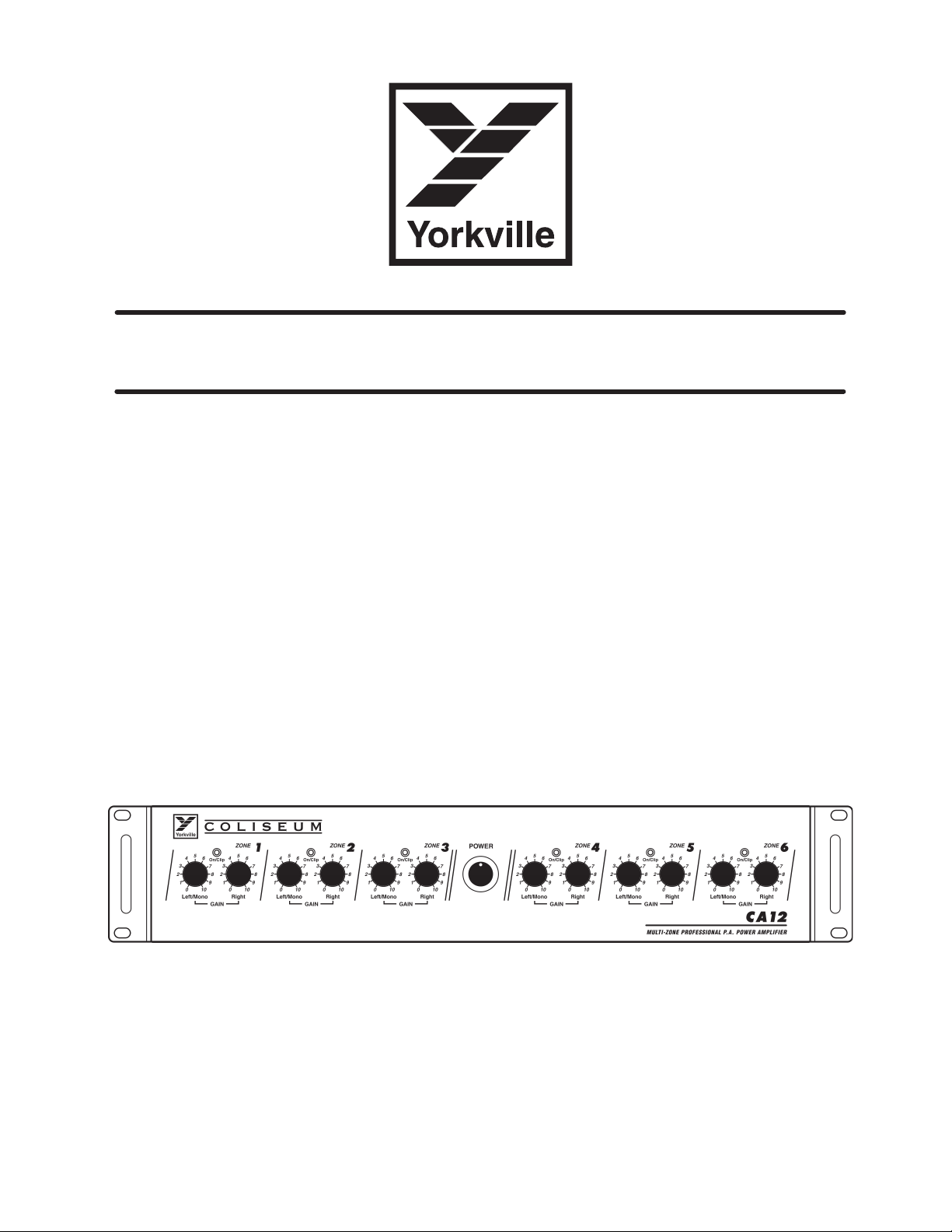
MULTI-ZONE PROFESSIONAL PA AMPLIFIER
MODEL TYPE: YS1048
COLISEUM
OWNER'S MANUAL
MANUEL DE L'UTILISTEUR
CA12

IMPORTANT SAFETY INSTRUCTIONS
safety-4v3.eps • Oct. 26/05
CAUTION:
TO REDUCE THE RISK OF ELECTRIC SHOCK, DO
NOT REMOVE COVER (OR BACK).
NO USER SERVICEABLE PARTS INSIDE.
REFER SERVICING TO QUALIFIED
SERVICE PERSONNEL.
INSTRUCTIONS PERTAINING TO A
RISK OF FIRE, ELECTRIC SHOCK,
OR INJURY TO PERSONS
Read Instructions
The Owner’s Manualshould be read and understood
before operation of your unit. Please, save these instructions for future reference.
Packaging
Keep the box and packaging materials, in case the unit
needs to be returned for service.
Warning
When using electric products, basic precautions should
always be followed, including the following:
Power Sources
Your unit should be connected to a power source only of the voltage
specified in the owners manual or as marked on the unit. This unit has a
polarized plug. Do not use with an extension cord or receptacle unless
the plug can be fully inserted. Precautions should be taken so that the
grounding scheme on the unit is not defeated.
Hazards
Do not place this product on an unstable cart, stand, tripod, bracket or
table. The product may fall, causing serious personal injury and serious
damage to the product. Use only with cart, stand, tripod, bracket, or
table recommended by the manufacturer or sold with the product.
Follow the manufacturer’s instructions when installing the product and
use mounting accessories recommended by the manufacturer.
The apparatus should not be exposed to dripping or splashing water;
no objects filled with liquids should be placed on the apparatus.
Te rminals marked with the “lightning bolt” are hazardous live; the
external wiring connected to these terminals require installation by an
instructed person or the use of ready made leads or cords.
Ensure that proper ventilation is provided around the appliance.
No naked flame sources, such as lighted candles, should be
placed on the apparatus.
Power Cord
The AC supply cord should be routed so that it is unlikely that it will be
damaged. If the AC supply cord is damaged DO NOT OPERATE THE UNIT.
Service
The unit should be serviced only by qualified service personnel.
AVIS:
AFIN DE REDUIRE LES RISQUE DE CHOC ELECTRIQUE,
N’ENLEVEZ PAS LE COUVERT (OU LE PANNEAU ARRIERE)
NE CONTIENT AUCUNE PIECE
REPARABLE PAR L’ UTILISATEUR.
CONSULTEZ UN TECHNICIEN QUALIFIE
POUR L’ENTRETIENT
INSTRUCTIONS RELATIVES AU RISQUE
DE FEU, CHOC ÉLECTRIQUE, OU
BLESSURES AUX PERSONNES
Veuillez Lire le Manuel
Il contient des informations qui devraient êtres comprises
avant l’opération de votre appareil. Conservez S.V. P. ces
instructions pour consultations ultérieures.
Emballage
Conservez la boite au cas ou l’appareil devait être
retourner pour réparation.
Attention:
Lors de l’utilisation de produits électrique, assurezvous d’adhérer à des précautions de bases incluant
celle qui suivent:
Alimentation
L’appareil ne doit être branché qu’à une source d’alimentation
correspondant au voltage spécifié dans le manuel ou tel qu’indiqué sur
l’appareil. Cet appareil est équipé d’une prise d’alimentation polarisée.
Ne pas utiliser cet appareil avec un cordon de raccordement à moins
qu’il soit possible d’insérer complètement les trois lames. Des
précautions doivent êtres prises afin d’eviter que le système de mise à
la terre de l’appareil ne soit désengagé.
Risque
Ne pas placer cet appareil sur un chariot, un support, un trépied ou une
table instables. L’appareil pourrait tomber et blesser quelqu’un ou subir
des dommages importants. Utiliser seulement un chariot, un support,
un trépied ou une table recommandés par le fabricant ou vendus avec
le produit. Suivre les instructions du fabricant pour installer l’appareil et
utiliser les accessoires recommandés par le fabricant.
Il convient de ne pas placer sur l’appareil de sources de flammes
nues, telles que des bougies allumées.
L’appeil ne doit pas être exposé à des égouttements d’eau ou des
éclaboussures et qu’aucun objet rempli de liquide tel que des vases
ne doit être placé sur l’appareil.
Assurez que lappareil est fourni de la propre ventilation.
Les dispositifs marqués d’une symbole “d’éclair” sont des parties
dangereuses au toucher et que les câblages extérieurs connectés à
ces dispositifs de connection extérieure doivent être effectivés par un
opérateur formé ou en utilisant des cordons déjà préparés.
Cordon d’Alimentation
Évitez d’endommager le cordon d’alimentation. N’UTILISEZ PAS
L’APPAREIL si le cordon d’alimentation est endommagé.
Service
Consultez un technicien qualifié pour l’entretien de votre appareil.
COLISEUM
CA12 Multi-Zone Professional PA Amplifier
1
2
3
Introduction
The CA12 is a major step forward in installation amplifier technology. Twelve mono Zone power amplifiers,
featuring 85% class D design technology, can operate as 6 independent Zone amplifiers. Self-explanatory
Input and Output connections are easy to follow since any of the 12 mono amplifiers can be connected to
either 70-Volt, 8-Ohm or 4-ohm speaker circuits.
Each of the 12 mono amplifiers has their own input and output connectors and level controls. Up to 6
stereo Zones (4-ohm or 70-Volt at 50 Watts / channel), 6 mono/bridged Zone amplifiers (110 Watt bridged
8-ohm or 140-Volt). Each Zone can be configured independently allowing a combination of Stereo 4-ohm
or 70 Volt and Mono/Bridged 8-ohm or 140 Volt Zones. Dual-function LEDs on the front panel provide both
activity and Clip indication for each pair of amplifiers, which also have their own button-selectable Limiter;
Stereo/Bridge modes and 4-ohm/70V modes are also selectable.
The Ch. Input Line/Bus switch selects between either the Bus Input (button depressed) or the individual
Zone’s Input signal. Additional features include: any amplifier with no signal at its input is automatically shut
off and the CA12 is able to operate either on 120V/60Hz or 220V/50Hz AC mains.
Features and Functions
AC Mains. The CA12 comes configured to connect to 115V/60Hz mains. For use with 230V/50Hz mains set
the rear panel Voltage Select switch to 230V (also, replace the T10.0AL/250V fuse with a T5.0AL/250V fuse).
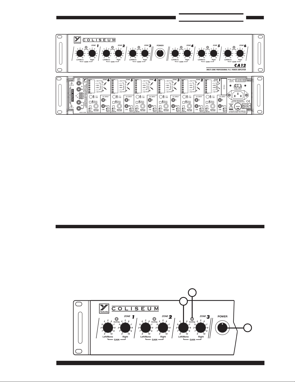
Front Panel
1. Left/Mono and Right Controls
These controls regulate the level for each amplifier. For the Zones set up in Mono/Bridge
mode only the Left/Mono Control will affect the level.
2. On/Clip LED
The individual channel’s On/Clip LED will flash to indicate activity, flashing red will indicate
clipping. Reduce levels if clipping is indicated (the LED does not indicate which Zone
channel is clipping).
3. Power
This switch turns the AC mains On or Off.
1
COLISEUM
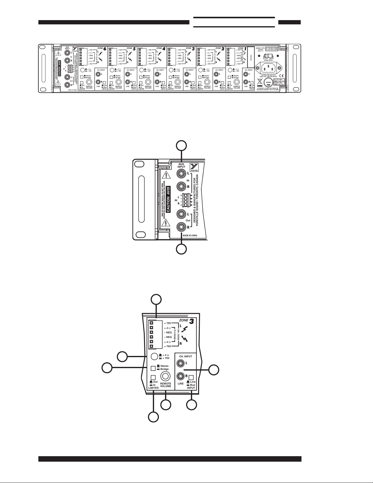
Rear Panel
4
5
6
7
8
9
10
11
12
4. Bus Inputs
RCA connectors and a screw terminal strip are
provided to connect your mixer, stereo tuner/preamp,
CD player or other audio media device.
Note: use only one type of source.
5. Bus Outputs
These RCA connectors are simply
in parallel with the Bus Inputs and
enable you to interconnect the CA12
with another CA12 or amplifier.
Note: only the Input Bus signals
will be patched to Output.
The Following Applies to Each
One of the Zone Input Sections
6. Ch Line Input
These inputs allow connection of
sources directly to the individual
channels. This input allows stereo,
line-level source or two separate
mono audio sources. If you Bridge the Zone’s pair
of amplifiers into an 8-ohm speaker circuit, use the
Left input and connect a mono source.
7. Line/Bus Button
Each Zone’s input source can be selected using
this switch. Depress the button to select
the audio program coming from the Bus
Input or leave it in the up position to use
the Zone’s Line Input.
8. Remote Volume Jack
Using a cable terminated with a
¼-inch mono phone plug, connect
your DC remote volume control
source (a potentiometer for example)
here. When connected, this feature
bypasses both front panel
controls for this Zone.
Note: Use a 50,000
ohm B taper
potentiometer.
Connect the wiper
of the potentiometer to the tip of the
stereo phone plug. Connect the ring
of the stereo phone plug to the top of
the potentiometer resistive element, and
connect the bottom of the potentiometer
resistive element to the sleeve of the
stereo phone plug. The tip, ring, and sleeve
electrical circuits must remain isolated from
any other ground or electrical connection.
9. Limiter In/Out Button
The Limiter In/Out button activates a pre-set
input limiter, which helps reduce the level
of accidental loud noises and clipping
distortion for each Zone (both channels
of each Zone).
10. Stereo/Bridge Button
For stereo, or dual-zone mono
operation, at 50 Watts per channel
leave this in the up position. To
combine (i.e. Bridge) the two into a
110-Watt mono amplifier, depress
the button. In Bridge mode, the +4
ohm / +70V button must be in the
+4 ohm position (depressed) to
allow for the 8-ohm speaker circuit,
not 4-ohms! In bridge mode, an
amplifier encounters a load that is
about one half of its actual value
– a 4-ohm load would therefore be
2-ohms to a bridged amp and if
the amplifier isn’t designed to run
safely into such a low impedance
(which the CA12 is not) damage may occur
to the amplifier. We do not recommend
connecting a 70V speaker circuit while in Bridge
mode as the output will be at 140V and the sound
can be distorted.
11. +4 ohm / 70V Button
Leave this switch in the up position if you are
connecting 4-ohm or 8-ohm speaker circuit
(Stereo mode). Depress the button to connect a
70V speaker circuit.
12. Speaker Connections
Insert bare wire ends here and
tighten the retaining screws to secure
properly. For a stereo Zone or dual
mono Zones, connect the + and –
system leads from each Zone to
one +4 ohm and its adjacent – Neg
terminal in the L & R terminal
groupings. In Bridge mode,
connect the + and – leads
from an 8-ohm speaker circuit
(not 4-ohms – see Stereo/
Bridge Button section above) to each
of the +4 ohm terminals.
2

COLISEUM
Amplificateur PA Professionnel Multi Zone CA12
1
2
3
Introduction
Le CA12 représente un avancement majeur pour la technologie d’amplificateur d’installation. Douze
amplificateurs de puissance mono de zone, qui mettent en vedette à 85% une conception de technologie
classe D, pouvant opérer comme 6 amplificateurs indépendants de Zone. Les connexions d’entrées et de
sorties sont faciles à comprendre puisque n’importe quel amplificateur, parmi les douze amplificateurs
monos, peut être connecté aux circuits de haut-parleurs 70-Volts, 8-Ohms ou 4-Ohms.
Les douze amplificateurs mono possèdent leurs propres connecteurs d’entrée et de sortie et leur
propre contrôle de niveau. Ils offrent jusqu’à six zones stéréos (4-ohms ou 70-Volt à 50 Watts / canal), 6
amplificateurs de zone mono/en pont (110 Watts en pont 8-ohms ou 140-Volts). Chaque zone peut être
configurées indépendamment pour offrir une combinaison de Zones Stéréo 4-ohms ou 70 Volts et Mono/
En Pont 8-ohms ou 140 Volts. Les DEL à double fonction sur le panneau avant indiquent l’activité et
l’écrêtage pour chaque paire d’amplificateurs qui possèdent aussi leur propre bouton sélecteur pour armer
ou désarmer le limiteur. Les modes Stéréo/En Pont et 4-ohms/70V sont aussi commutables.
Le commutateur d’entrée de canal Line/Bus permet de sélectionner soit l’entrée BUS (bouton enfoncé)
soit le signal d’entrée individuel de zone. Les caractéristiques suivantes sont aussi incluses: n’importe quel
amplificateur ne possédant pas de signal à son entrée est automatiquement éteint et le CA12 est capable
d’opérer avec alimentation CA de 120V/60Hz ou 220V/50Hz.
Caractéristiques et Fonctions
Alimentation principale CA. Le CA12 est configuré à l’usine pour être branché à une alimentation de
115V/60Hz. Pour utilisation avec une alimentation de 230V/50Hz réglez le sélecteur de voltage sur le
panneau arrière à la position 230V (remplacez aussi le fusible T10.0AL/250V avec un fusible T5.0AL/250V).
Panneau Avant
1. Contrôles Gauche/Mono et Droit
Ces contrôles règle le niveau pour chaque amplificateur. Pour les Zones en mode Mono/Bridge seul le
contrôle Gauche/Mono affectera le niveau de signal.
2. DEL On/Clip
Les DEL On/Clip sur chaque canal clignote pour indiquer l’activité. Un clignotement rouge indique l’écrêtage.
Réduisez le niveau si il y a écrêtage (la DEL n’indique pas quel canal de Zone produit l’écrêtage).
3. Alimentation (Power)
Ce sélecteur est utilisé pour la mise en marche de l’alimentation principale.
3

COLISEUM
Panneau Arrière
4
5
6
7
8
9
10
11
12
4. Entrées Bus
L’appareil est équipé de connecteurs RCA et
d’une barrette de connexion pour le raccordement
de votre mixeur, récepteur/préamplificateur
stéréo, Lecteur CD ou autre de signal audio.
Note: n’utilisez qu’un type de source.
5. Sorties Bus
Ces connecteurs RCA sont simplement branchés en
parallèle avec les entrées Bus et vous
permettent de raccorder le CA12 à
un autre CA12 ou à un amplificateur.
Note: seul les signaux
présents à l’entrée Bus seront
acheminés à la sortie.
Le texte qui suit s’applique
à chacune des sélections
d’entrées de Zone
6. Entrées Ligne
Ces entrées permettent le
branchement de sources directement
aux canaux individuels. Elles
permettent le raccordement d’une
source de niveau ligne stéréo ou de
deux sources audio mono séparées.
Si vous branchez la paire d’amplificateurs de Zone en
pont dans un circuit haut-parleur de 8-ohms, utilisez
l’entrée gauche et connectez une source mono.
7. Bouton Ligne/Bus
Chaque source d’entrée de Zone peut être
sélectionné en utilisant ce sélecteur.
Appuyez sur le bouton pour sélectionner un
programme audio provenant de l’entrée Bus
ou laissez le bouton en position sortie
pour utiliser l’entrée ligne de la Zone.
8. Prise Pour Contrôle de Volume à Distance
À l’aide d’un câble équipé de fiche
¼-pouce mono, connectez à cette prise
votre source de contrôle
de volume à distance (par
exemple un potentiomètre).
Lorsque connectée,
cette fonction
désengage le deux
contrôles du panneau
avant pour cette Zone.
Note: Utiliser un potentiomètre de
50000 ohms à répartition linéaire
de la résistance. Connectez la tige du
curseur du potentiomètre à la pointe
de la fiche stéréo. Branchez la bague
de la prise stéréo à la tige supérieure
de l’élément résistif du potentiomètre, et
connectez la tige inférieure de l'élément résistif du
potentiomètre au manchon de la fiche stéréo. Les
circuits électriques de la pointe, de la bague et du
manchon doivent demeurer isolée de tout autre
branchement à la masse ou connexion électrique.
9. Bouton Limiteur In/Out
Le bouton Limiteur In/Out arme le limiteur préréglé
à l’usine qui aide à réduire le niveau des bruits
forts accidentels et aide à prévenir la distorsion
pour chaque Zone (les deux canaux de
chaque Zone).
10. Bouton Stéréo/En Pont
Gardez ce bouton à la position sortie
pour opération stéréo, ou mono à
double zone, avec 50 Watts par canal.
Pour combiner (ex.: en pont) les
deux amplificateurs en un seul ampli
mono de 110-Watts, appuyez sur le
bouton. Lorsqu’en mode « En Pont
», le bouton +4 ohms / +70V doit être
à la position +4 ohms (enfoncé) pour
permettre un circuit de haut-parleur
de 8-ohms, pas 4-ohms! Lorsqu’en
mode «En Pont», un amplificateur
rencontre un charge équivalente à
approximativement la moitié de sa
valeur véritable – une charge de
4-ohms serait alors équivalente à une
charge de 2-ohms pour un amplificateur
en pont. Des dommages pourraient survenir à
l’amplificateur si il n’est pas conçu pour opérer
de façon sécuritaire avec une telle basse impédance
(le CA12 ne l’est pas). Nous ne recommandons pas
le raccordement d’un circuit de haut-parleur 70V
lorsqu’en mode “en pont” puisque la sortie sera de
140V et cela pourrait produire de la distorsion.
11. Bouton +4 ohms / 70V
Gardez ce bouton à la position sortie
si vous branchez un circuit de hautparleur de 4-ohms ou 8-ohms (mode
Stéréo). Appuyez sur le bouton pour
le raccordement à un circuit de hautparleur 70V.
12. Bornes de Branchement Pour Haut-Parleur
Insérez ici la partie du fil
dénudée et serrez la vis pour
maintenir le fil en place. Pour
une Zone stéréo ou une zone
double mono, connectez les
conducteurs + et – du système de
chaque Zone à la borne +4 ohms et à
sa borne négative (-) adjacente dans
le groupe de bornes Gauche et Droite.
Lorsqu’en mode En Pont, connectez
les conducteurs + et – du circuit de
haut-parleur 8-ohms (pas 4-ohms – voir la section
ci-dessus « Bouton Stéréo/En Pont ») à chacune
des bornes +4 ohms.
4

COLISEUM
Specifications
Type
Installation Power Amplifier
Power @ min. impedance (Watts)
50W / ch. (4 ohm or 70 V; 25 W / ch. (8 ohm)
100W (8 ohms BRIDGED)
Minimum Impedance (ohms)
4 ohms (8 ohms bridged)
Frequency Response (Hz +/-3dB)
40 Hz - 20 kHz
Hum and Noise (dB)
-97 dB
Input Channels
12 ( 6 Stereo Zones)
Channel - inputs
RCA / Terminal strip on Main Bus input
Channel - controls
Gain
Input Sensitivity (mV)
650 mV
Line Out (type / configuration)
Bus Output RCA
LED Indicators
Power, Clip
External speaker output / location
Terminal Strip (rear)
Dimensions (DWH, inches)
16.75 x 16.75 x 3.25
Dimensions (DWH, cm)
43.5 x 43 x 8.5
Weight (lbs / kg)
45 / 20.5
MULTI-ZONE PROFESSIONAL PA AMPLIFIER
COLISEUM
CA12
Spécifications
Type
Amplificateur d'Installation
Puissance @ impédance min. (watts)
50W / ch. (4 ohm or 70 V; 25 W / ch. (8 ohm)
100W (8 ohms En Pont)
Impédance minimum (ohms )
4 ohms (8 ohms en pont)
Réponse en fréquence (Hz +/-3dB)
40hz - 20khz
Bruit et Bourdonnement (dB)
-97 dB
Canaux d’entrées
12 ( 6 Stereo Zones)
Entrées - Canal
RCA / Terminal strip - Entrées Bus
Contrôle – Canal
Gain
Sensibilité d’entrée (mV)
650 mV
Sorite Ligne (type / configuration)
Sorties Bus (RCA)
DEL Indicatrices
Power, Clip
Prise de sortie pour haut-parleur externe / location
Terminal Strip (arrière)
Dimensions (PLH, pouces)
16.75 x 16.75 x 3.25
Dimensions (PLH, cm)
43.5 x 43 x 8.5
Poids (livres / kg)
45 / 20.5
5

COLISEUM
6


1
3
2
1 3
2
+12V
1 3
2
1 3
2
+12V
1 3
2
1 3
2
+12V
1 3
2
1 3
2
+12V
1
3
2
1 3
2
+12V
1 3
2
1 3
2
+12V
Bloc k Diag r a m fo r CA12
MODEL TYPE: YS1048
BUS INPUT/OUTPUT
CH. INPUT
VOLUME
LIMITER SW. BRIDGE SW.
POWER SW.
REMOTE VOLUME JACK
SOURCE SELECTION
AVC CONTRO L
SSM2164
LIMITER CONTROL
NJM2761
POWER AMPLIFIER
TDA8920BTH
OUTPUT
SELECTION SW.
OUTPUT
TRANSFORMER
OUTPUT
TRANSFORMER
ZONE 1
AUTO POWER ON/OFF
CONTROL
CH. INPUT
VOLUME
LIMITER SW. BRIDGE SW.
POWER SW.
REMOTE VOLUME JACK
SOURCE SELECTION
AVC CONTRO L
SSM2164
LIMITER CONTROL
NJM2761
POWER AMPLIFIER
TDA8920BTH
OUTPUT
SELECTION SW.
OUTPUT
TRANSFORMER
OUTPUT
TRANSFORMER
ZONE 2
AUTO POWER ON/OFF
CONTROL
CH. INPUT
VOLUME
LIMITER SW. BRIDGE SW.
POWER SW.
REMOTE VOLUME JACK
SOURCE SELECTION
AVC CONTRO L
SSM2164
LIMITER CONTROL
NJM2761
POWER AMPLIFIER
TDA8920BTH
OUTPUT
SELECTION SW.
OUTPUT
TRANSFORMER
OUTPUT
TRANSFORMER
ZONE 3
AUTO POWER ON/OFF
CONTROL
CH. INPUT
VOLUME
LIMITER SW. BRIDGE SW.
POWER SW.
REMOTE VOLUME JACK
SOURCE SELECTION
AVC CONTRO L
SSM2164
LIMITER CONTROL
NJM2761
POWER AMPLIFIER
TDA8920BTH
OUTPUT
SELECTION SW.
OUTPUT
TRANSFORMER
OUTPUT
TRANSFORMER
ZONE 4
AUTO POWER ON/OFF
CONTROL
CH. INPUT
VOLUME
LIMITER SW. BRIDGE SW.
POWER SW.
REMOTE VOLUME JACK
SOURCE SELECTION
AVC CONTRO L
SSM2164
LIMITER CONTROL
NJM2761
POWER AMPLIFIER
TDA8920BTH
OUTPUT
SELECTION SW.
OUTPUT
TRANSFORMER
OUTPUT
TRANSFORMER
ZONE 5
AUTO POWER ON/OFF
CONTROL
CH. INPUT
VOLUME
LIMITER SW. BRIDGE SW.
POWER SW.
REMOTE VOLUME JACK
SOURCE SELECTION
AVC CONTRO L
SSM2164
LIMITER CONTROL
NJM2761
POWER AMPLIFIER
TDA8920BTH
OUTPUT
SELECTION SW.
OUTPUT
TRANSFORMER
OUTPUT
TRANSFORMER
ZONE 6
AUTO POWER ON/OFF
CONTROL

Unlimited Warranty
Yorkville's two and ten-year unlimited warranty on this product is transferable
and does not require registration with Yorkville Sound or your dealer. If this
product should fail for any reason within two years of the original purchase
date (ten years for the wooden enclosure), simply return it to your Yorkville
dealer with original proof of purchase and it will be repaired free of charge.
This includes all Yorkville products, except for the YSM Series studio
monitors, Coliseum Mini Series and TX Series Loudspeakers.
Freight charges, consequential damages, weather damage, damage as a result
of improper installation, damages due to exposure to extreme humidity, accident
or natural disaster are excluded under the terms of this warranty. Warranty does
not cover consumables such as vacuum tubes or par bulbs. See your Yorkville
dealer for more details. Warranty valid only in Canada and the United States.
Garantie Illimitée
La garantie illimitée de deux et dix ans de ce produit est transférable. Il n`est pas
nécessaire de faire enregistrer votre nom auprès de Yorkville Sound ou de votre
détaillant. Si, pour une raison quelconque, ce produit devient défectueux durant
les deux années qui suivent la date d`achat initial (dix ans pour l`ébénisterie),
retournez-le simplement à votre détaillant Yorkville avec la preuve d`achat original
et il sera réparé gratuitement. Ceci inclus tous les produits Yorkville à l`exception
de la série de moniteurs de studio YSM, la mini série Coliseum et de la série TX.
Les frais de port et de manutention ainsi que les dommages indirects ou
dommages causés par désastres naturels, extrême humidité ou mauvaise
installation ne sont pas couverts par cette garantie. Cette garantie ne couvre
pas les produits consommables tels que lampe d`amplificateur ou ampoules
"PAR". Voir votre détaillant Yorkville pour plus de détails. Cette garantie n’est
valide qu’au Canada et aux États Unis d’Amérique.
www.yorkville.com
REAL Gear.
REAL People.
Yo rkville Sound
550 Granite Court
Pickering, Ontario
L1W-3Y8 CANADA
Canada
Voice: (905) 837-8481
Fax: (905) 837-8746
Yo rkville Sound Inc.
4625 Witmer Industrial Estate
Niagara Falls, New Yo rk
14305 USA
U.S.A.
Voice: (716) 297-2920
Fax: (716) 297-3689
Printed in China
Two & Ten Year Warranty
Two
&
Ten

WORLD HEADQUARTERS
CANADA
U.S.A.
Yorkville Sound
550 Granite Court
Pickering, Ontario
L1W-3Y8 CANADA
Voice: (905) 837-8481
Fax: (905) 837-8746
Yorkville Sound Inc.
4625 Witmer Industrial Estate
Niagara Falls, New Yo rk
Voice: (716) 297-2920
Manual-Owners-CA12-00-1v2 • Nov 30/2009
Printed in China
14305 USA
Fax: (716) 297-3689
 Loading...