

Page 1
®
723389-XTG-C-0214
TECHNICAL GUIDE
R-410A
ZF SERIES
3 - 6.3 TON
50 Hz
Export Only
Description
YORK® ZF Series units are convertible single package high
efficiency rooftops with a common roof curb for the 3, 4, 5 and
6.3 Ton sizes. Although the units are primarily designed for curb
mounting on a roof, they can also be slab-mounted at ground
level or set on steel beams above a finished roof.
All ZF Series units are self-contained and asse mb le d on rigid
full perimeter base rails allowing for overhead rigging. Every
unit is completely charged, wired, piped and tested at the
factory to provide a quick and easy field installation.
All models (including those with an economizer) are convertible
between bottom and horizontal duct connections.
ZF Series units are available in the following configurations:
cooling only, cooling with electric heat, and cooling with one
stage gas heat. Electric heaters are available as factoryinstalled option or field install e d accessory.
FOR DISTRIBUTION USE ONLY - NOT TO BE USED AT POINT OF RETAIL SALE
Page 2
723389-XTG-C-0214
Table of Contents
Description . . . . . . . . . . . . . . . . . . . . . . . . . . . . . . . . . . . . . . . . . . . . . . . . . . . . . . . . . . . . . . . . . . . . . . . . . . . . . . . . . . . . . . . . . . . . 1
Table of Contents . . . . . . . . . . . . . . . . . . . . . . . . . . . . . . . . . . . . . . . . . . . . . . . . . . . . . . . . . . . . . . . . . . . . . . . . . . . . . . . . . . . . . . . 2
Component Location . . . . . . . . . . . . . . . . . . . . . . . . . . . . . . . . . . . . . . . . . . . . . . . . . . . . . . . . . . . . . . . . . . . . . . . . . . . . . . . . . . . . 2
Nomenclature . . . . . . . . . . . . . . . . . . . . . . . . . . . . . . . . . . . . . . . . . . . . . . . . . . . . . . . . . . . . . . . . . . . . . . . . . . . . . . . . . . . . . . . . . . 4
Features and Benefits . . . . . . . . . . . . . . . . . . . . . . . . . . . . . . . . . . . . . . . . . . . . . . . . . . . . . . . . . . . . . . . . . . . . . . . . . . . . . . . . . . . . 5
Guide Specifications . . . . . . . . . . . . . . . . . . . . . . . . . . . . . . . . . . . . . . . . . . . . . . . . . . . . . . . . . . . . . . . . . . . . . . . . . . . . . . . . . . . . . 8
Physical Data . . . . . . . . . . . . . . . . . . . . . . . . . . . . . . . . . . . . . . . . . . . . . . . . . . . . . . . . . . . . . . . . . . . . . . . . . . . . . . . . . . . . . . . . . . 12
Capacity Performance . . . . . . . . . . . . . . . . . . . . . . . . . . . . . . . . . . . . . . . . . . . . . . . . . . . . . . . . . . . . . . . . . . . . . . . . . . . . . . . . . . 14
Airflow Performance . . . . . . . . . . . . . . . . . . . . . . . . . . . . . . . . . . . . . . . . . . . . . . . . . . . . . . . . . . . . . . . . . . . . . . . . . . . . . . . . . . . . 30
Electrical Data . . . . . . . . . . . . . . . . . . . . . . . . . . . . . . . . . . . . . . . . . . . . . . . . . . . . . . . . . . . . . . . . . . . . . . . . . . . . . . . . . . . . . . . . . 34
Typical Field Power and Control Wiring . . . . . . . . . . . . . . . . . . . . . . . . . . . . . . . . . . . . . . . . . . . . . . . . . . . . . . . . . . . . . . . . . . . . 35
Weights and Dimensions . . . . . . . . . . . . . . . . . . . . . . . . . . . . . . . . . . . . . . . . . . . . . . . . . . . . . . . . . . . . . . . . . . . . . . . . . . . . . . . . 36
Typical Wiring Diagrams . . . . . . . . . . . . . . . . . . . . . . . . . . . . . . . . . . . . . . . . . . . . . . . . . . . . . . . . . . . . . . . . . . . . . . . . . . . . . . . . 41
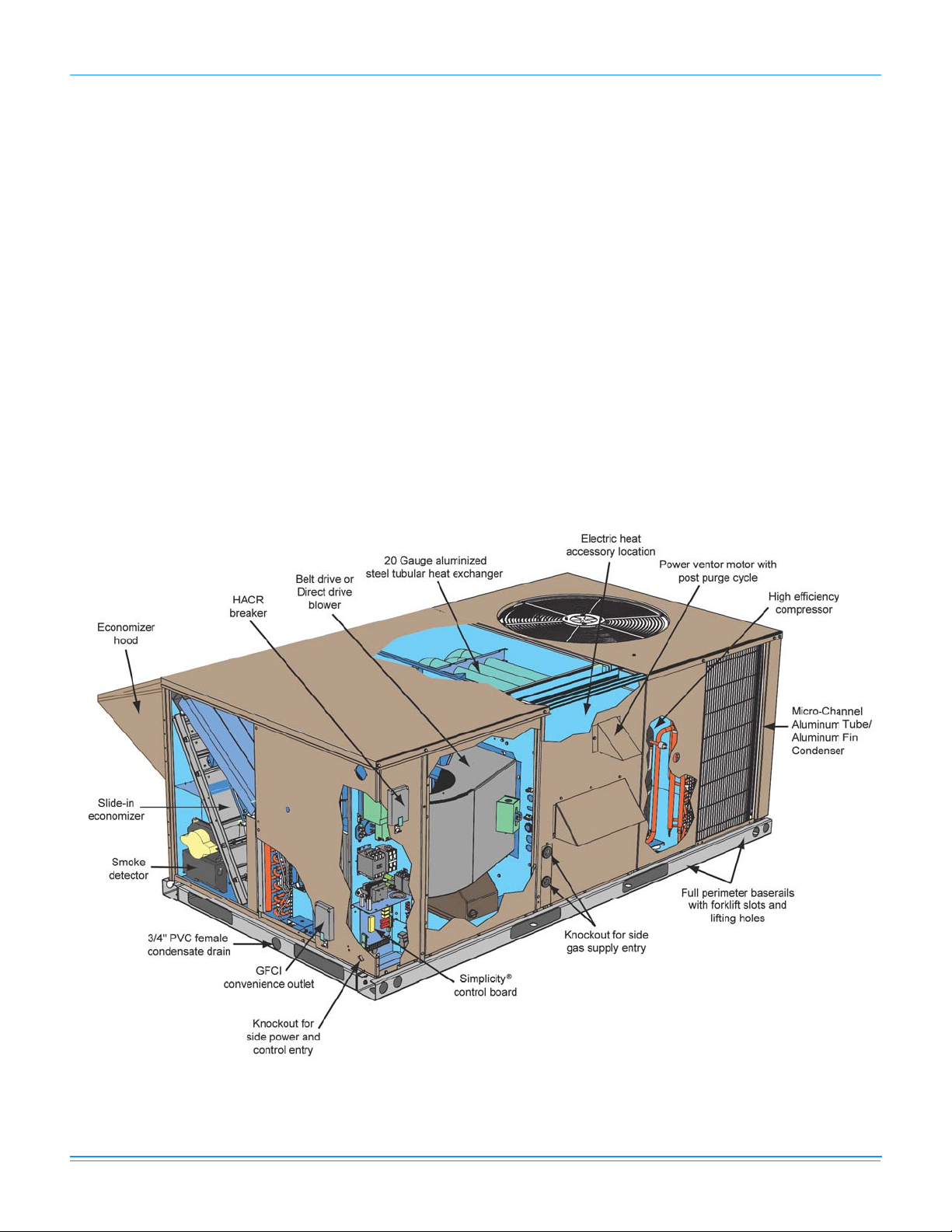
Component Location
Gas/Electric
2 Johnson Controls Unitary Products
Page 3
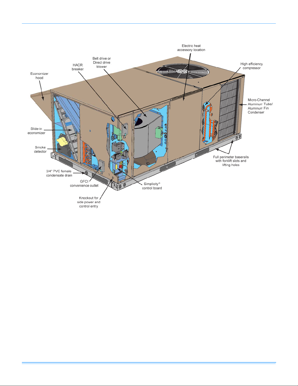
Electric/Electric
723389-XTG-C-0214
Johnson Controls Unitary Products 3
Page 4
723389-XTG-C-0214
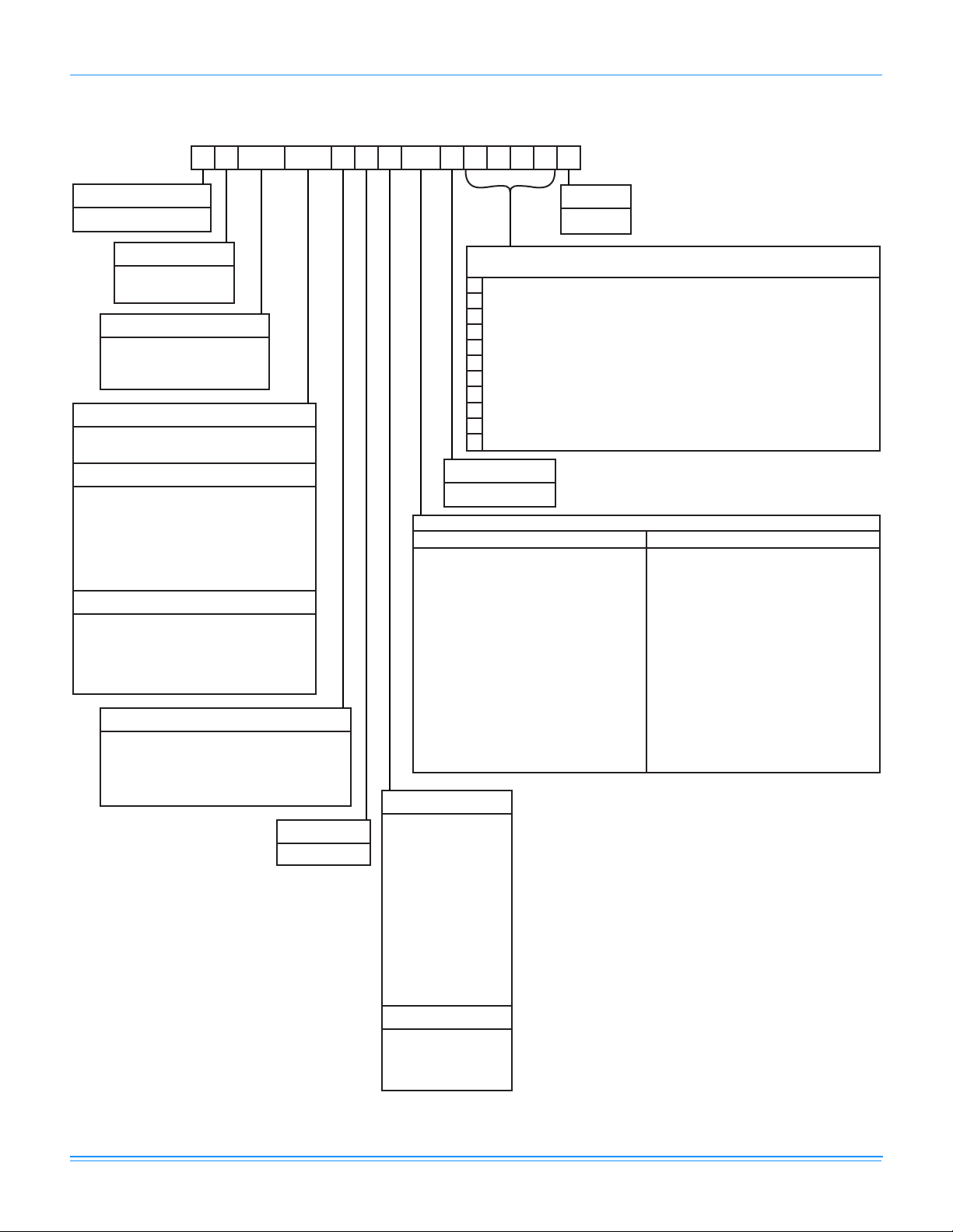
Z F 048 N04 A 7 A AA 1 0 1 2 4 A
Z = A/C, Single Pkg., R-410A
Product Category
Airflow
Product Generation
1 = First Generation
C00 = Cooling Only. Suitable for Field
Installed Electric Heat
Heat Type and Nominal Heat Capacity
E05 = 5 KW
E07 = 7 KW
E10 = 10 KW
E15 = 15 KW
E20 = 20 KW
E30 = 30 KW
Gas Heat Options
Electric Heat Options
036 = 3.0 Ton
Nominal Cooling Capacity
048 = 4.0 Ton
060 = 5.0 Ton
076 = 6.3 Ton
Product Identifier
F = 13.0 SEER, A/C
= 11.0 EER, A/C
Voltage
7 = 380/415-3-50
Product Style
A = Style A
A = No Options Installed
Installation Options
B = Option 1
C = Option 2
D = Options 1 & 2
E = Option 3
F = Option 4
G = Options 1 & 3
H = Options 1 & 4
J = Options 1, 2 & 3
K = Options 1, 2, & 4
L = Options 1,3 & 4
M = Options 1, 2, 3, & 4
N = Options 2 & 3
P = Options 2 & 4
Q = Options 2, 3, & 4
R = Options 3 & 4
1 = Disconnect
2 = Non-Pwr'd Conv. Outlet
3 = Smoke Detector S.A.
4 = Smoke Detector R.A.
Options
SS Drain Pan
Configuration Options (not required for all units)
These four digits will not be assigned until a quote is requested, or an order placed.
CPC Controller, DFS, APS
Johnson Controller UNT 1126 (N2 protocol), DFS, APS
Honeywell Controller, DFS, APS
Novar Controller, DFS, APS
Simplicity IntelliComfort Controller
Simplicity IntelliComfort Controller w/ModLinc
2" Pleated filters
BAS Ready Economizer (2-10 V.D.C. Actuator Without a Controller)
Any Combination of Additional Options that Don’t Have an Option Code Pre-assigned
AA = None
Standard Cabinet
AB = Phase Monitor
AC = Coil Guard
AD = Dirty Filter Switch
AE = Phase Monitor & Coil Guard
AF = Phase Monitor & Dirty Filter Switch
AG = Coil Guard & Dirty Filter Switch
AH = Phase Monitor, Coil Guard & Dirty Filter Switch
AS = Bottom Drain Connection
RC = Coil Guard & American Flag
TA = Technicoat Condenser Coil
TJ = Technicoat Evaporator Coil
TS = Technicoat Evaporator and Condenser Coil
Additional Options
Hinged & Toolless Access Cabinet
BA = Hinged & Toolless Filter, Motor and Electrical
Access Panels
BB = Phase Monitor, Hinged & Toolless Filter, Motor
and Electrical Access Panels
BC = Coil Guard, Hinged & Toolless Filter, Motor and
Electrical Access Panels
BD = Dirty Filter Switch, Hinged & Toolless Filter,
Motor and Electrical Access Panels
BE = Phase Monitor & Coil Guard, Hinged & Toolless
Filter, Motor and Electrical Access Panels
BF = Phase Monitor & Dirty Filter Switch, Hinged &
Toolless Filter, Motor and Electrical Access
Panels
BG = Coil Guard & Dirty Filter Switch, Hinged &
Toolless Filter, Motor and Electrical Access
Panels
BH = Phase Monitor, Coil Guard & Dirty Filter Switch,
Hinged & Toolless Filter, Motor and Electrical
Access Panels
York Commercial Comfort System (YCCS) Rtu Controller
1
1. 3 thru 6.3 Ton Units
EA = ElectroFin Condenser Coil
EJ = ElectroFin Evaporator Coil
ES = ElectroFin Cond & Evap Coils
A = Direct Drive
B = Direct Drive/Economizer
D = Direct Drive/Motorized Damper
N = Belt Drive
P = Belt Drive/Economizer
R = Belt Drive/Motorized Damper
N04 = 40 MBH Output Aluminized Steel, 1 Stage (036)
N06 = 60 MBH Output Aluminized Steel, 1 Stage (048)
N08 = 80 MBH Output Aluminized Steel, 1 Stage
(060, 076)
S04 = 40 MBH Output Stainless Steel, 1 Stage (036)
S06 = 60 MBH Output Stainless Steel, 1 Stage (048)
S08 = 80 MBH Output Stainless Steel, 1 Stage
(060, 076)
Nomenclature
4 Johnson Controls Unitary Products
Page 5
723389-XTG-C-0214
Features and Benefits
Standard Features
• High Efficiency - High efficiency 3 thru 5 Ton units reach
13.0 SEER, 6.3 Ton reach 10.9 EER. Gas/electric units
have electronic spark ignition and power vented
combustion with steady state efficiencies of 80%. These
efficiencies exceed all legislated minimum levels and
provide low operating costs.
• Coil Technology – All ZF condensers utilize MicroChannel “all-aluminum” condensers which provide
improved heat transfer capabilities and reduced charge
volumes. All evaporators utilize a conventional copper
tube/aluminum fin design for proven reliability and
performance.
• Convertible Airflow Design - All models (including those
with an economizer) are suitable for either bottom or
horizontal duct connections. For bottom duct, remove the
sheet metal panels from the supply and return air openings
through the base of the unit. For horizontal duct, remove
the supply and return air panels on the rear of the unit.
• System Protection - Suction line freezestats are supplied
on all units to protect against loss of charge and coil
frosting when the economizer operates at low outdoor air
temperatures while the compressors are running. Every
unit has solid-core liquid line filter-driers and high and lowpressure switches. Internal compressor protection is
standard on all compressors.
• Advanced Controls - The Simplicity
boards have standardized a number of features
previously available only as options or by utilizing
additional controls.
• Low Ambient - An integrated low-ambient control
allows all units to operate in the cooling mode down to
0F outdoor ambient without additional assistance.
Optionally, the control board can be pro g r a mme d to
lockout the compressors when the outdoor air
temperature is low or when free cooling is available.
The
Simplicity
will effectively operate the cooling system down to
0°F when this product is applied in a comfort cooling application for people. An economizer is typically included in this type of application. When
applying this product for process cooling applications (computer rooms, switchgear, etc.), please
reference applications bulletin AE-011-07 or call
the applications department for Unitary Products
@ 1-877-UPG-SERV for guidance. Additional
accessories may be needed for stable operation at
temperatures below 30° F.
• Anti-Short Cycle Protection - To aid compressor life,
an anti-short cycle delay is incorporated into the
® control board used in this product
®
Lite™ control
standard controls. Compressor reliability is further
ensured by programmable minimum run times. For
testing, the anti-short cycle delay can be temporarily
overridden with the push of a button.
• Fan Delays - Fan on and fan off delays are fully
programmable. Furthermore, the heating and cooling
fan delay times are independent of one another. All units
are programmed with default values based upon their
configuration of cooling and heat.
• Safety Monitoring - The control board monitors the
high and low-pressure switches, the freezestats, the gas
valve, if applicable, and the temperature limit switch on
gas and electric heat units. The unit control board will
alarm on ignition failures, compressor lockouts and
repeated limit switch trips.
• Nuisance Trip Protection and Strikes - To prevent
nuisance trouble calls, the control board uses a “three
times, you’re out” philosophy. The high and lowpressure switches and the freezestats must trip three
times within two hours before the unit control board will
lock out the associated compressor.
• On Board Diagnostics - Each alarm will energize a
trouble light on the thermostat, if so equipped, and flash
an alarm code on the control board LED. Each high and
low-pressure switch alarm as well as each freezestat
alarm has its own flash code. The control board saves the
five most recent alarms in memory, and these alarms can
be reviewed at any time. Alarms and programmed values
are retained through the loss of power.
• Reliable - From the beginning - All units undergo
computer automated testing before they leave the factory.
Units are tested for refrigerant charge and pressure, unit
amperage, and 100% functionality. For the long term - All
ZF Series units are painted with a long lasting, powder
paint that stands up over the life of the unit. The paint
used has been proven by a 1000 hour salt spray test.
• Flexible Placement - All models and configurations share
the same cabinet/footprint and thus the same roof curb.
You have the flexibility to set one curb and choose the
correct tonnage size and heating option after the internal
loads have been determined.
• Full Perimeter Base Rails - The permanently attached
base rails provide a solid foundation for the entire unit and
protect the unit during shipment. The rails offer forklift
access from 3 sides, and rigging holes are available so that
an overhead crane can be used to place the units on a roof.
• Easy Installation - Gas and electric utility knockouts are
supplied in the unit underside as well as the side of the
unit. A clearly identified location is provided to mount a
field supplied electrical disconnect switch. Utility
connections can be made quickly and with a minimum
amount of field labor.
• Wide Range of Indoor Airflows - Indoor fan motors are
direct-drive 3 and 4 ton or belt-drive 5 and 6.3 ton type
providing maximum flexibility to handle most airflow
requirements.
• Gas Heat Operation - All three phase models with gas
heat have minimum steady state efficiency of 80%. Each
section includes a durable heat exchanger with
Johnson Controls Unitary Products 5
Page 6
723389-XTG-C-0214
aluminized steel or optional stainless steel tubes, a
redundant gas valve, spark ignition, power venting, an
ignition module for 100% shut-off and all of the safety
controls required to meet the latest ANSI standards.
The gas supply piping can be routed into the heating
compartment through a hole in the base pan of the unit or
through a knockout in the piping panel on the front of the
unit.
Electric Heat Operation - All electric heat models are
wired for a single power source and include a bank of
nickel chromium elements mounted at the discharge of
the supply air blower to provide a high velocity and
uniform distribution of air across the heating elements.
Every element is fully protected against excessive
temperature by thermal limit switches.
The power supply wiring can be routed into the control
box through a threaded pipe connection (field supplied) in
the base pan of the unit or through a knockout in the
wiring panel on the side of the unit.
• Warranty - All models include a 1-year limited warranty
on the complete unit. Compressors and electric heater
elements each carry a 5-year warranty. Aluminized steel
and stainless steel tubular heat exchangers carry a 10year warranty.
Factory Installed Options
• Single Input Electronic Enthalpy Economizers Includes a slide-in / plug-in damper assembly with fully
modulating spring-return motor actuator capable of
introducing up to 100% outdoor air with nominal 1%
leakage type dampers.
The enthalpy system contains one sensor that monitors
the outdoor air and determines when the air is cool
enough and dry enough to provide free cooling.
The rain hood is painted to match the basic unit and must
be field-assembled before installing.
• Motorized Outdoor Air Intake Damper -Includes a slidein / plug-in damper assembly with a 2-position, spring
return motor actuator which opens to a pre-set position
whenever the supply air blower is operating and will drive
fully closed when the blower unit shuts down.
The rain hood is painted to match the basic unit and must
be field assembled before installing.
• Technicoat Condenser Coils - The condenser coils are
coated with a phenolic coating for protection against
corrosion due to harsh environments.
• Technicoat Evaporator Coil - The evaporator coils are
coated with a phenolic coating for protection against
corrosion due to harsh environments.
• ElectroFin® E-coat Condenser Coils - The condenser
coils are coated with an epoxy polymer coating to protect
against corrosion.
• ElectroFin® E-coat Evaporator Coils - The evaporator
coils are coated with an epoxy polymer coating to protect
against corrosion.
• Electric Heaters - Wired for single point power supply.
These nickel chromium heater elements are provided with
limit and automatic reset capability to prevent operation at
excessive temperatures.
• Filter Options - Standard units are shipped with 1" throwaway filters installed. 2" pleated filters are offered as a
factory installed option.
• Disconnect Switch - For gas heat units and cooling units
with electric heat, a HACR breaker sized to the unit is
provided. For cooling only units, a switch sized to the
largest electric heat available for the particular unit is
provided. Factory installed option only.
• Smoke Detectors - (supply air & return air) The smoke
detectors stop operation of the unit by interrupting power
to the control board if smoke is detected within the air
compartment.
Factory installed smoke detectors in the return air, may
be subjected to freezing temperatures during “off” times
due to out side air infiltration. These smoke detectors
have an operational limit of 32°F to 131°F. Smoke
detectors installed in areas that could be out side those
limitations will have to be moved to prevent having false
alarms.
• Coil Guard - Customers can purchase a coil guard kit to
protect the condenser coil from damage. This is not a hail
guard kit.
• Stainless Steel Heat Exchanger - For applications in
corrosive environments, this option provides a full
stainless steel heat exchanger assembly.
• Stainless Steel Drain Pan - An optional rustproof
stainless steel drain pan is available to provide years of
trouble-free operation in corrosive environments.
• Bottom Drain Connection - An optional bottom drain
connection is available for inside the curb connections for
applications in cold environments to reduce freezing drain
lines.
• Phase Monitors - Designed to prevent unit damage. The
phase monitor will shut the unit down in an out-of phase
condition.
• Dirty Filter Switch - This kit includes a differential
pressure switch that energizes the fault light on the unit
thermostat, indicating that there is an abnormally high
pressure drop across the filters. Factory installed option or
field installed accessory.
• Hinged & Toolless Filter, Motor and Electrical Access
Panels - This option allows for easy access and
maintenance.
NOTE: Knobs are shipped inside the unit to prevent shipping
damage. These must be field installed for tool-less
operation.
6 Johnson Controls Unitary Products
Page 7

723389-XTG-C-0214
• High Static Drive - May include a belt, blower pulley,
motor pulley or a motor change to enhance blower
performance.
Control Options
• BAS - Building Automation System Controls Simplicity®
INTELLI-Comfort™ Control - The York® Simplicity®
INTELLI-Comfort™ control is factory installed. It includes a
supply air sensor, a return air sensor, and an outside air
sensor. There are provisions for a field installed dirty filter
indicator switch, an air-proving switch, an Outside Air
Humidity sensor, a Return Air Humidity sensor, an Inside
IAQ sensor, and an Outside Air IAQ sensor. Construction
mode operation, 365-day real time clock with 7 day
programming plus holiday scheduling is built-in. Two
different modes of demand ventilation are achieved through
the INTELLI-Comfort™ using CO
inside CO2 sensor to perform Demand Ventilation. It can
also use an Outside CO2 sensor to perform Differential
Demand Ventilation. It uses a Patented Comfort Ventilation
algorithm to provide comfortable ventilation air
temperature. The patented economizer-loading algorithm
will protect the equipment when harsh operating conditions
exist. Humidity in the occupied space or return duct can be
monitored and controlled via humidity sensors and the onboard connection for hot gas re-heat system. It uses the
INTELLI-Start™ algorithm to maximize energy savings by
recovering the building from the Unoccupied Setpoints to
the Occupied Setpoints just in time for the Occupied Time
Period to begin. The Simplicity
balances space temperature, ventilation air temperature,
and humidity for ultimate comfort.
CO
2
• Simplicity
®
INTELLI-Comfort™ with ModLINC
Control - The York® Simplicity® INTELLI-Comfort™ with
ModLINC control is factory installed. It includes all the
features of the INTELLI-Comfo rt™ co ntrol with an
additional control to translate communications from
MODBUS to the BACnet MSTP protocol.
• Novar® BAS Control - The Novar® building automation
system controller is factory installed. Incudes supply air
sensor, return air sensor, dirty filter indicator switch, and
air proving switch.
• Johnson Controls BAS Control - The Johnson Control
YK-UNT-1126 building automation system controller is
factory installed. Includes supply air sensor, return air
sensor, dirty filter indicator switch, and air proving switch.
• CPC BAS Control - The Computer Process Controls
Model 810-3060 ARTC Advanced Rooftop building
automation system controller is factory installed. Includes
supply air sensor, return air sensor, dirty filter indicator
switch and air proving switch.
• Honeywell BAS Control - The Honeywell W7750C
building automation system controller is factory installed.
Includes air supply sensor, return air sensor, dirty filter
indicator switch, and air proving switch.
sensors. It uses an
2
®
INTELLI-Comfort™
• York Commercial Comfort System (YCCS) - Provides
rooftop system integration for YCCS single zone and
change-over bypass systems.
Field Installed Accessories
• Single Input Electronic Enthalpy Economizers -
Includes a slide-in / plug-in damper assembly with fully
modulating spring-return motor actuator capable of
introducing up to 100% outdoor air with nominal 1%
leakage type dampers.
The enthalpy system contains one sensor that monitors
the outdoor air and determines when the air is cool
enough and dry enough to provide free cooling.
The rain hood is painted to match the basic unit and must
be field-assembled before installing.
• Motorized Outdoor Air Intake Damper -Includes a slidein / plug-in damper assembly with a 2-position, spring
return motor actuator which opens to some pre-set
position whenever the supply air blower is operating and
will drive fully closed when the blower unit shuts down.
The rain hood is painted to match the basic unit and must
be field assembled before installing.
• Electric Heaters - wired for single point power supply.
These nickel chromium heater elements are provided with
limit and automatic reset capability to prevent operation at
excessive temperatures.
• Roof Curbs - Eight and fourteen-inch high roof curbs
provide a water-tight seal between the unit and the finished
roof. These full perimeter curbs meet the requirements of
the National Roofing Contractors Association (NRCA) and
are shipped knocked-down for field assembly.
Roof curbs are designed to fit inside the base rails of the
unit and include both a wood nailing strip and duct hanger
supports.
• High Altitude Natural Gas - Burner orifices and pilot
orifices are provided for proper furnace operation at
altitudes up to 6,000 feet.
• Propane - Burner orifices, pilot orifices and gas valve
parts are provided to convert a natural gas furnace to
propane.
• High Altitude Propane - Burner orifices and pilot orifices
are provided for proper furnace operation at altitudes up
to 6,000 feet. This accessory supplements the basi c
propane conversion kit.
• Low Nox Kit - Required to reduce the emission of
nitrogen oxides below 40 nano grams per joule.
• Power Exhaust - Our single input economizer options are
available with power exhaust. Whenever the outdoor air
intake dampers are opened for free cooling, the exhaust
fan will be energized to prevent the conditioned space from
being over-pressurized during economizer operation.
The power exhaust option can only be used on bottom
duct configurations.
Johnson Controls Unitary Products 7
Page 8

723389-XTG-C-0214
• Barometric Relief Damper - This damper accessory can
be used to relieve internal building air pressure on units
with an economizer without power exhaust. This
accessory includes a rain hood, a bird screen and a fully
assembled damper. With bottom duct connections, the
damper should be mounted over the opening in the return
air panel. With horizontal ductwork, the accessory should
be mounted on the return air duct.
• Enthalpy Accessory Control Kit - This kit contains the
required components to convert a single enthalpy
economizer to dual enthalpy.
• Burglar Bars - Mount in the supply and return openings
to prevent entry into the duct work.
• Flue Exhaust Extension Kit - In locations with wind or
weather conditions which may interfere with proper
exhausting of furnace combustion products, this kit can be
installed to prevent the flue exhaust from entering nearby
fresh air intakes.
Sensor - Senses CO2 levels and automatically
• CO
2
overrides the economizer when levels rise above the
present limits.
• Coil Guard - Customers can purchase a coil guard kit to
protect the condenser coil from damage. This is not a hail
guard kit.
• Hail Guard - Hail Guard kit is available to prevent unit
from hail damage. This is a sloped hood that fits above
the coil.
• Gas Piping Kit - This kit supplies all necessary fittings
and shut off valve.
Guide Specifications
General
Units shall be manufactured by Johnson Controls Unitary
Products in an ISO 9001 certified facility.
York's ZF units are convertible single package units. Although
the units are primarily designed for curb mounting on a roof,
they can also be slab-mounted at ground level or set on steel
beams above a finished roof. Cooling only, cooling with gas
heat and cooling with electric heat models are available with a
wide variety of factory-mounted options and field-installed
accessories to make them suitable for almost every application.
All units are self-contained and assembled on full perimeter
base rails with holes in the four corners for overhead rigging.
Every unit is completely piped, wired, charged and tested at the
factory to simplify the field installation and to provide years of
dependable operation. All models (including those with an
economizer) are suitable for either bottom or horizontal duct
connections. Models with power exhaust are suitable for bottom
duct connections only. For bottom duct, remove the sheet metal
panels from the supply and return air openings through the
base of the unit. For horizontal duct, remove the supply and
return air panels on the rear of the unit.
All non-Scroll compressors include crankcase heaters and all
compressors have internal pressure relief. Every refrigerant
circuit includes a liquid line filter-drier, a discharge line high
pressure switch and a suction line with a freezestat and low
pressure/loss of charge switch.The unit control circuit includes
a 75 VA transformer, a 24-volt circuit breaker and a relay board
with a compressor lockout circuit, a terminal strip for thermostat
wiring, plus an additional set of pin connectors to simplify the
interface of additional field controls. All models include a 1-year
limited warranty on the complete unit. Compressors and electric
heater elements carry a 5-year warranty. Aluminized steel and
Stainless steel tubular heat exchangers carry a 10-year
warranty.
Description
Units shall be factory-assembled, single packaged, Electric
Cooling/Gas Heat, Electric Cooling/Optional Electric Heat are
designed for outdoor mounted installation.
The 3 ton, 4 ton and 5 ton units shall have minimum SEER
rating of 13.0. The 6.3 Ton shall have 10.9 EER. They shall
have built-in field convertible duct connections for down
discharge supply/return or horizontal discharge supply/return,
and be available with factory installed options or field installed
accessories. The units shall be factory wired, piped, charged
with R-410A refrigerant and factory tested prior to shipment. All
unit wiring shall be both numbered and color coded. All units
the cooling performance shall be rated in accordance with DOE
and ARI test procedures.
Unit Cabinet
Unit cabinet shall be constructed of galvanized steel, with
exterior surfaces coated with a non-chalking, powdered paint
finish, certified at 1000 hours salt spray test per ASTMB117
standards. Indoor blower section shall be insulated with a
minimum 1/2” thick insulation, coated on the airside. Aluminum
foil faced insulation shall be used in the furnace compartment
and be fastened with ridged fasteners to prevent insulation from
entering the air stream. Cabinet panels shall be “large” size,
easily removable for servicing and maintenance. Full perimeter
base rails shall be provided to assure reliable transit of
equipment, overhead rigging and proper sealing on roof curb
applications. Disposable 1" filters shall be furnished and be
accessible through a removable access door, sealed airtight.
Units filter track shall be designed to accommodate either 1" or
2" filters. Fan performance measuring ports shall be provided
on the outside of the cabinet to allow accurate air
measurements of evaporator fan performance without removing
panels or creating air by-pass of the coils. Condensate pan
shall be internally sloped and conform to ASHRAE 62-89 selfdraining standards. Condensate connection shall be a minimum
of 3/4” I.D. female and be a ridged mount connection.
8 Johnson Controls Unitary Products
Page 9

723389-XTG-C-0214
Indoor (Evaporator) Fan Assembly
The indoor fan shall be a factory installed direct-drive or beltdrive assembly that includes an adjustable pitch motor pulley.
Units shall be designed not to operate above service factor. Fan
wheel shall be double-inlet type with forward-curved blades,
dynamically balanced to operate smoothly throughout the entire
range of operation. Airflow design shall be constant air volume.
Bearings shall be sealed and permanently lubricated for longer
life and no maintenance.
Outdoor (Condenser) Fan Assembly
The outdoor fan shall be of the direct-driven propeller type,
discharge air vertically, have aluminum blades riveted to a
corrosion resistant steel spider bracket and shall be
dynamically balanced for smooth operation. The outdoor fan
motor shall be totally enclosed with permanently lubricated
bearings, internally protected against overload conditions and
staged independently.
Refrigerant Components
Compressor:
a. Shall be internally protected with internal high-pressure
relief and over temperature protection.
b. Shall have internal spring isolation and sound muffling to
minimize vibration and noise, and be externally isolated
on a dedicated, independent mounting.
Coils:
a. Evaporator coils shall have aluminum plate fins
mechanically bonded to seamless internally enhanced
copper tubes with all joints brazed. Special Phenolic
coating shall be available as a factory option.
b. Evaporator coils shall be of the direct expansion, draw-
thru design.
c. Condenser coils shall have Micro-Channel aluminum
tube, aluminum fins.
d. Condenser coils shall be of the direct expansion, draw-
thru design.
Refrigerant Circuit and Refrigerant Safety Components shall
include:
a. Independent fixed-orifice devices.
b. Filter drier/strainer to eliminate any moisture or foreign
matter.
c. Accessible service gage connections on both suction
and liquid lines to charge, evacuate, and measure
refrigerant pressure during any necessary servicing or
troubleshooting, without losing charge.
d. The refrigeration system shall provide at least 15°F of
sub-cooling at design conditions.
Unit Controls
a. Unit shall be complete with self-contained low-voltage
control circuit protected by a resettable circuit breaker on
the 24-volt transformer side.
b. Unit shall incorporate a lockout circuit which provides
reset capability at the space thermostat or base unit,
should any of the following standard safety devi ces trip
and shut off compressor.
c. Loss-of-charge/Low-pressure switch.
d. High-pressure switch.
e. Freeze-protection thermostat, evaporator coil.
f. Unit shall incorporate “AUTO RESET” compressor over
temperature, over current protection.
g. Unit shall operate with conventional thermostat designs
and have a low voltage terminal strip for easy hook-up.
h. Unit control board shall have on-board diagnostics and
fault code display.
i. Standard controls shall include anti-short cycle and low
voltage protection, and permit cooling operation down to
0°F.
j. Control board shall monitor each refrigerant safety switch
independently.
k. Control board shall retain last 5 fault codes in non volatile
memory which will not be lost in the event of a power loss.
Gas Heating Section
Shall be designed with induced draft combustion with post
purge logic, energy saving direct spark ignition, and redundant
main gas valve. Venter wheel shall be constructed of stainless
steel for corrosion resistance. The heat exchanger shall be of
the tubular type, constructed of T1-40 aluminized steel for
corrosion resistance and allowing minimum mixed air entering
temperature of 25°F. Burners shall be of the inshot type,
constructed of aluminum coated steel and contain air mixture
adjustments. All gas piping shall enter the unit cabinet at a
single location through either the side or curb without any field
modifications. Integrated control boards shall provide timed
control of evaporator fan functioning and burner ignition.
Heating section shall be provided with the following minimum
protection:
a. Primary and auxiliary high-temperature limit switches.
b. Induced draft motor speed sensor.
c. Flame roll out switch.
d. Flame proving controls.
e. If any of the above safety devices trip, a LED (light-
emitting diode) indicator shall flash a diagnostic code that
indicates which safety switch has tripped.
Johnson Controls Unitary Products 9
Page 10

723389-XTG-C-0214
Electric Heating Section
An electric heating section, with nickel chromium elements,
shall be provided in a range of 5 thru 30 KW, offering two
stages of capacity - The heating section shall have a primary
limit control(s) and automatic reset to prevent the heating
element system from operating at an excessive temperature.
The heating section assembly shall slide out of the unit for easy
maintenance and service. Units with Electric Heating shall be
wired for a single point power supply with branch circuit fusing
(where required).
Unit Operating Characteristics
Unit shall be capable of starting and running at 125°F outdoor
temperature, exceeding maximum load criteria of ARI Standard
210/240. The compressor, with standard controls, shall be
capable of operation down to 0°F outdoor temperature. Unit
shall be provided with fan time delay to prevent cold air delivery
before heat exchanger warms up (Gas heat only).
Electrical Requirements
All unit power wiring shall enter unit cabinet at a single factory
provided location and be capable of side or bottom entry, to
minimize roof penetrations and avoid unit field modifications.
Separate side and bottom openings shall be provided for the
control wiring.
Standard Limited Warranties
• Compressor 5 Years
• Heat Exchanger 10 Years
• Electric Heat Element 5 Years
• Other Parts 1 Year
Optional Outdoor Air
Shall be made available by either/or:
• Electronic Enthalpy Automatic Economizer - Outdoor
and return air dampers that are interlocked and positioned
by a fully-modulating, spring return damper actuator. The
maximum leakage rate for the outdoor air intake dampers
shall not exceed 2% when dampers are fully closed and
operating against a pressure differential of 0.5 IWG. A unitmounted potentiometer shall be provided to adjust the
outdoor and return air damper assembly to take in CFM of
outdoor air to meet the minimum ventilation requirement of
the conditioned space during normal operation. During
economizer operation, a mixed-air temperature control
shall modulate the outdoor and return air damper assembly
to prevent the supply air temperature from dropping below
55°F. Changeover from compressor to economizer
operation shall be provided by an integral electronic
enthalpy control that feeds input into the basic module. The
outdoor intake opening shall be covered with a rain hood
that matches the exterior of the unit. Water eliminator/filters
shall be provided. Simultaneous economizer/compressor
operation is also possible. Dampers shall fully close on
power loss.
• Motorized Outdoor Air Dampers - Outdoor air dampers
are positioned by a 2-position, spring-return damper
actuator. The maximum leakage rate for the outdoor air
intake dampers shall not exceed 2% when dampers are
fully closed and operating against a pressure differential
of 0.5 IWG. A unit-mounted potentiometer shall be
provided to adjust the outdoor damper assembly to take in
the design CFM of outdoor air to meet the ventilation
requirements of the conditioned space during normal
operation. Whenever the indoor fan motor is energized,
the dampers open up to one of two pre-selected positions
- regardless of the outdoor air enthalpy. Dampers return to
the fully closed position when the indoor fan motor is deenergized. Dampers shall fully close on power loss.
Other Pre-engineered Accessories Available
• Roof Curb - 14"and 8” high, full perimeter curb with wood
nailer (shipped knocked-down).
• Barometric Relief Damper - Contains a rain hood, air
inlet screen, exhaust damper and mounting hardware.
Used to relieve internal air pressure through the unit.
• Propane Conversion Kit - Contains new orifices and gas
valve parts to convert from natural to L.P. gas. One per
unit required.
• High Altitude - Natural Gas - Contains orifices required
for applications between 2000 and 6000 feet altitude.
High Altitude - Propane Gas - Contains orifice s requ ired
•
for applications between 2000 and 6000 feet altitude.
Must be used with propane conversion kit.
• Low Nox - Required to reduce the emission of nitrogen
oxides below 40 nanograms per joule.
• Gas Piping - Contains 1/2” pipe nipples, fittings and gas
cock (including panel assess gaskets) required for bottom
gas supply connection with external shut off.
• Power Exhaust Option - To work in conjunction with
economizers.
• Electric Heaters
• Economizer/motorized Damper Rain Hood - Contains
all hood panels and the hardware for assembling.
• Manual Outdoor Air Damper
• Coil Guard Kit - Guard for cooling coil.
• Hail Guard
• Flue Exhaust Extension
10 Johnson Controls Unitary Products
Page 11

723389-XTG-C-0214
OTHER FACTORY INSTALLED OPTIONS
• Power Exhaust Option - To work in conjunction with
economizers.
• Stainless Steel Heat Exchanger
• Stainless Steel Drain Pan
• Bottom Drain Connection
• Technicoat Phenolic Coated Condenser And
Evaporator Coil
• Electronic Single Enthalpy Economizer
• Dirty Filter Switch
• Phase Monitor
•Coil Guard
• Non-powered GFI Convenience Outlet
• BAS Controls (Simplicity
®
INTELLI-Comfort™, CPC,
Johnson, Honeywell, Novar, York Commercial
Comfort System (YCCS))
• Bas Ready Economizer (2-10 V.D.C. Actuator Without
a Controller)
• Hinged Filter Door Access And Toolless Access
Panels
• 2" Pleated Filters
• Disconnect Switch
• Supply Air Smoke Detector
• Return Air Smoke Detector
• Direct Drive Or Belt Drive Blower
Johnson Controls Unitary Products 11
Page 12
723389-XTG-C-0214
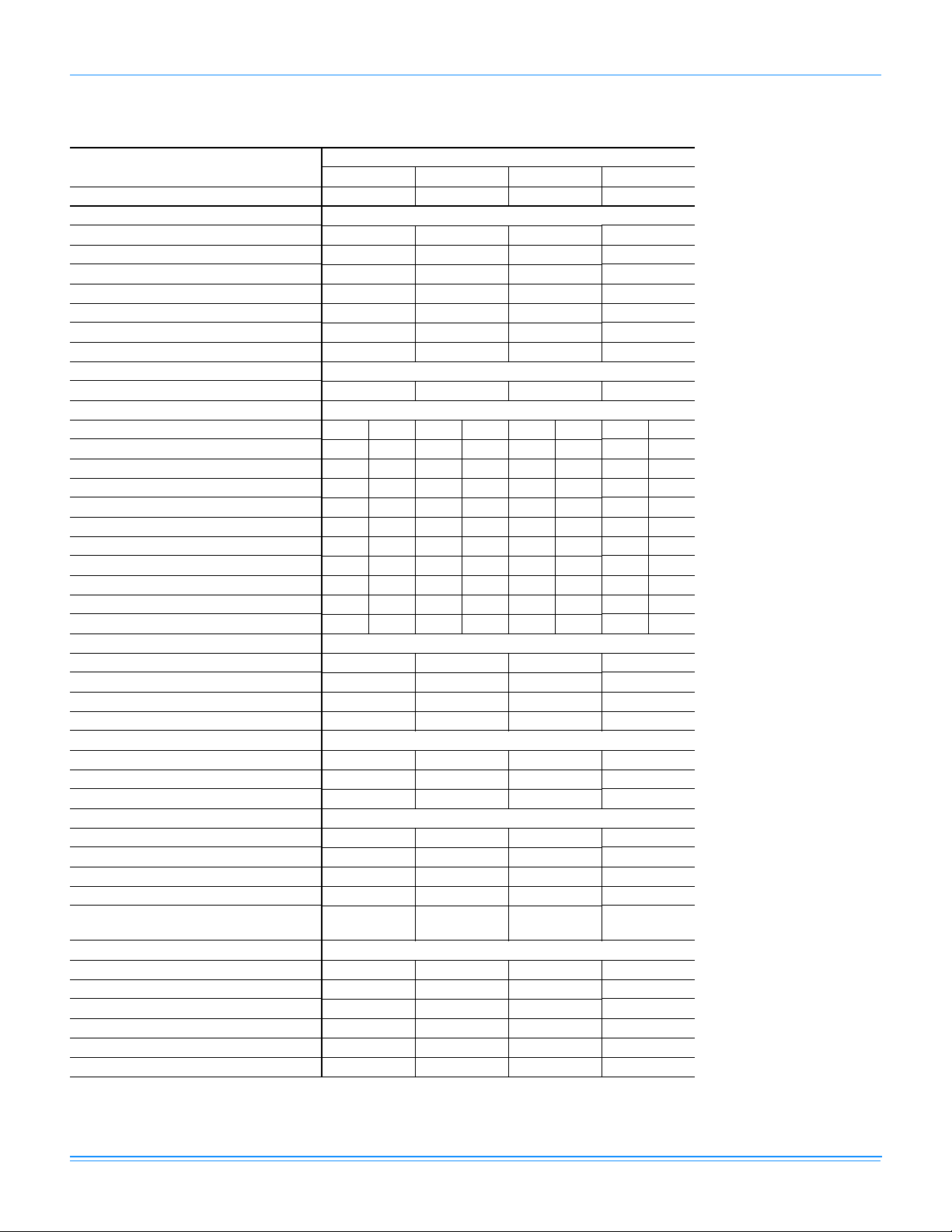
Physical Data
ZF036-076 Physical Data
2-pass
Models
2-pass
Microchannel
2-pass
Microchannel
Component
Nominal Tonnage 3.0 4.0 5.0 6.3
ARI COOLING PERFORMANCE
Gross Capacity @ ARI A point (Btu)
ARI net capacity (Btu)
EER (Net)
SEER
Nominal CFM
System power (KW)
Refrigerant type
Refrigerant charge (lb-oz)
System 1 4-12 5-4 5-4 6-8
ARI HEATING PERFORMANCE
Heating model
Heat input (K Btu)
Heat output (K Btu)
AFUE %
Steady state efficiency (%)
No. burners
No. stages
Temperature Rise Range (ºF) 15-45 45-75 25-70 45-75 25-55 35-75 25-55 30-75
Gas Limit Setting (ºF) - Direct Drive 240170210165---Gas Limit Setting (ºF) - Belt Drive ----210210210210
Gas piping connecting (in.)
DIMENSIONS (inches)
Length
Width
Height
OPERATING WT. (lbs.)
COMPRESSORS
Type
Quantity
Unit Capacity Steps (%)
CONDENSER COIL DATA
Face area (Sq. Ft.) 16.3 16.3 16.3 16.3
Rows
Fins per inch
Tube diameter (in./mm)
Circuitry Type
EVAPORATOR COIL DATA
Face area (Sq. Ft.)
Rows
Fins per inch
Tube diameter
Circuitry Type
Refrigerant control
ZF036 ZF048 ZF060 ZF076
36400 51300 60400 72600
35200 47000 57800 69100
11.5 11.5 11.5 10.9
13.0 13.0 13.0 -
1200 1600 2000 2500
4.2 4.2 4.9 6.3
R-410A R-410A R-410A R-410A
N04 N08 N06 N10 N08 N10 N08 N10
50 100 75 125 100 125 100 125
40 80 60 100 80 100 80 100
80.9 80.5 80.9 80.3 80.5 80.3 80.5 80.3
- - - - - --2 4 3 5 4 545
1 1 1 1 1 111
1/2 1/2 1/2 1/2 1/2 1/2 1/2 1/2
82 1/4 82 1/4 82 1/4 82 1/4
44 7/8 44 7/8 44 7/8 44 7/8
32 5/8 32 5/8 32 5/8 32 5/8
468 541 569 640
Recip Recip Scroll Scroll
1 1 11
100 100 100 100
1 1 11
23 23 23 23
0.71 / 18 0.71 / 18 0.71 / 18 1.0 / 25.4
2-pass
Microchannel
5.06 5.06 5.06 5.06
3 4 44
13 13 13 13
0.375 0.375 0.375 0.375
Intertwined Intertwined Intertwined Intertwined
Fixed Orifice Fixed Orifice Fixed Orifice Fixed Orifice
Microchannel
12 Johnson Controls Unitary Products
Page 13
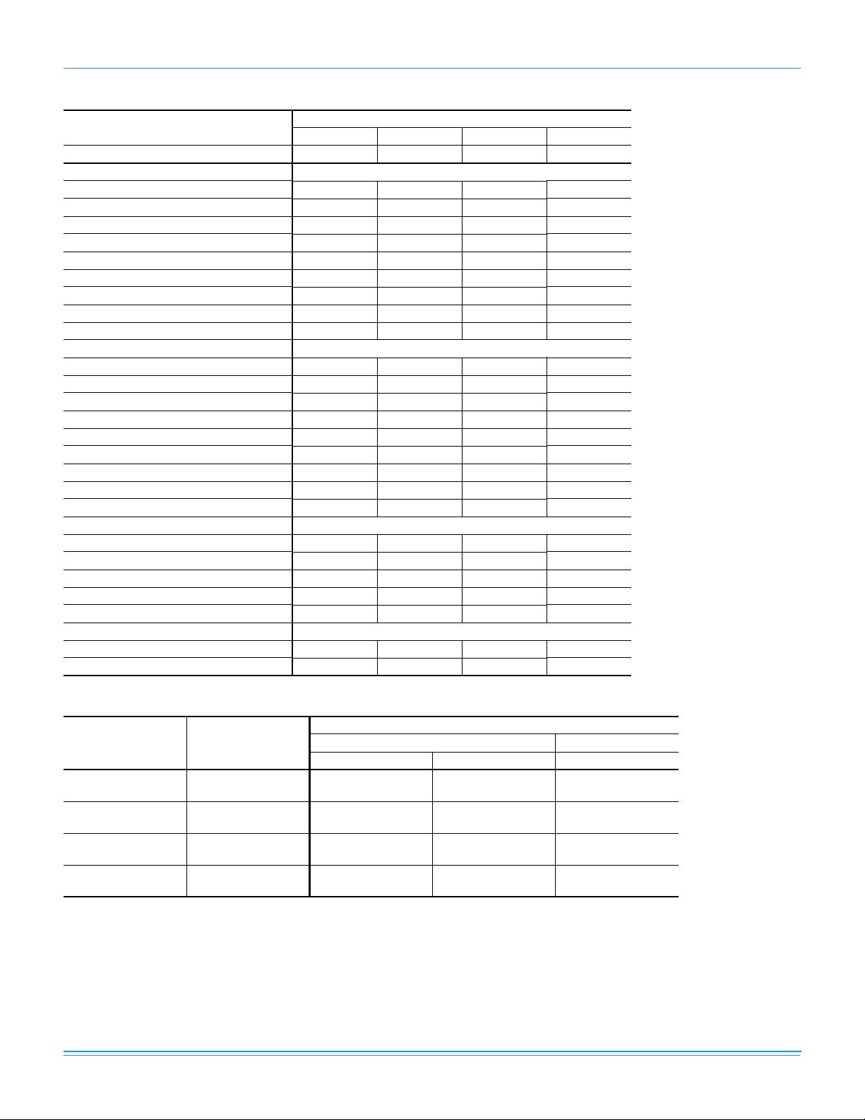
ZF036-076 Physical Data (Continued)
723389-XTG-C-0214
Component
Nominal Tonnage 3.0 4.0 5.0 6.3
CONDENSER FAN DATA
Quantity
Fan diameter (Inch)
Type
Drive type
Quantity of motors
Motor HP each
No. speeds
RPM
Nominal total CFM
BELT DRIVE EVAP FAN DATA
Quantity
Fan Size (Inch)
Type
Motor Sheave - - 1VL44 IVM50
Blower Sheave - - AK54 AK56
Belt - - A35 A36
Motor HP each - - 1-1/2 1-1/2
RPM
Frame size
DIRECT DRIVE EVAP FAN DATA
Quantity
Fan Size (Inch)
Type
Motor HP each
RPM
FILTERS
15” x 20” x 1” or 2”
14” x 25” x 1” or 2”
ZF036 ZF048 ZF060 ZF076
1 1 11
24 24 24 24
Prop Prop Prop Prop
Direct Direct Direct Direct
1 1 11
1/2 1/2 1/2 3/4
1 1 11
1090 1090 1090 1090
3450 3450 3450 3750
- - 11
- - 12 x 10 12 x 11
- - Centrifugal Centrifugal
- - 1450 1450
- - 56 56
1 1 --
12 x 10 12 x 10 --
Centrifugal Centrifugal --
1/2 3/4 --
1050 1050 --
2 2 22
1 1 11
Models
ZF036-076 Unit Limitations
Size
(Tons)
ZF036
(3.0)
ZF048
(4.0)
ZF060
(5.0)
ZF076
(6.3)
Unit Voltage
380/415-3-50 342 456 125
380/415-3-50 342 456 125
380/415-3-50 342 456 125
380/415-3-50 342 456 125
Applied Voltage Outdoor DB Temp
Min Max Max (°F)
Unit Limitations
Johnson Controls Unitary Products 13
Page 14
723389-XTG-C-0214
Capacity Performance
ZF036-076 Cooling Capacities
ZF036 (3.0 Ton) Imperial
Air on
Evaporator Coil
CFM
900
1050
1200
1350
1500
900
1050
1200
1350
1500
WB
(°F)
Total
Capacity
(MBh)
77 49.0 2.3 24.0 20.4 16.8 - - - 44.0 2.5 22.1 18.5 14.8 - - 72 44.0 2.3 28.2 24.7 21.1 17.5 - - 39.5 2.6 26.3 22.7 19.1 15.4 - 67 39.1 2.4 32.5 28.9 25.3 21.7 18.1 - 35.0 2.6 30.5 26.9 23.3 19.7 16.0 62 36.7 2.2 36.7 36.7 32.4 28.8 25.3 21.7 32.1 2.5 32.1 32.1 28.7 25.1 21.5 17.9
57 37.4 2.2 37.4 37.4 36.0 32.4 28.8 25.3 33.1 2.5 33.1 33.1 31.6 28.0 24.4 20.8
77 49.5 2.3 24.0 21.0 17.3 - - - 44.9 2.6 22.7 19.1 15.5 - - 72 44.5 2.4 29.0 25.3 21.7 18.0 - - 40.3 2.6 27.4 23.6 19.9 16.2 - 67 39.4 2.4 34.0 29.7 26.0 22.3 18.6 - 35.7 2.6 32.0 28.2 24.3 20.5 16.6 62 37.1 2.3 37.1 37.1 33.4 29.3 25.2 21.1 32.7 2.5 32.7 32.7 30.0 25.9 21.7 17.6
57 37.8 2.3 37.8 37.8 37.1 33.0 28.8 24.7 33.8 2.5 33.8 33.8 33.0 28.8 24.6 20.5
77 50.0 2.4 24.0 21.5 17.8 - - - 45.7 2.6 23.3 19.7 16.1 - - 72 44.9 2.4 29.8 26.0 22.3 18.5 - - 41.1 2.7 28.4 24.6 20.7 16.9 - 67 39.8 2.5 35.5 30.5 26.7 22.9 19.1 - 36.4 2.7 33.5 29.4 25.3 21.2 17.2 62 37.5 2.4 37.5 37.5 34.3 29.8 25.2 20.6 33.4 2.6 33.4 33.4 31.3 26.6 21.9 17.3
57 38.2 2.4 38.2 38.2 38.2 33.5 28.8 24.0 34.4 2.6 34.4 34.4 34.4 29.7 24.9 20.2
77 51.9 2.3 25.9 23.4 19.1 - - - 47.3 2.6 25.8 21.5 17.2 - - 72 46.6 2.4 32.6 28.2 23.9 19.6 - - 42.4 2.6 31.0 26.6 22.1 17.7 - 67 41.4 2.4 39.2 33.0 28.7 24.3 19.9 - 37.6 2.7 36.1 31.6 27.0 22.5 17.9 62 38.9 2.3 38.9 38.9 37.3 32.5 27.8 23.0 34.5 2.5 34.5 34.5 33.4 28.5 23.7 18.8
57 39.6 2.3 39.6 39.6 39.6 34.8 30.0 25.2 35.5 2.5 35.5 35.5 35.5 30.7 25.8 20.9
77 53.8 2.3 27.9 25.3 20.4 - - - 48.8 2.6 28.4 23.3 18.3 - - 72 48.3 2.3 35.4 30.4 25.5 20.6 - - 43.8 2.6 33.6 28.6 23.5 18.5 - 67 42.9 2.4 42.9 35.5 30.6 25.7 20.8 - 38.8 2.6 38.8 33.8 28.7 23.7 18.7 62 40.3 2.2 40.3 40.3 40.2 35.3 30.3 25.4 35.6 2.5 35.6 35.6 35.5 30.4 25.4 20.4
57 41.1 2.2 41.1 41.1 41.1 36.1 31.2 26.3 36.7 2.5 36.7 36.7 36.7 31.7 26.6 21.6
77 39.1 2.7 20.2 16.5 12.9 - - - 34.1 3.0 18.3 14.6 10.9 - - 72 35.0 2.8 24.4 20.7 17.1 13.4 - - 30.5 3.0 22.5 18.8 15.1 11.4 - 67 31.0 2.8 28.6 24.9 21.3 17.6 13.9 - 27.0 3.0 26.7 23.0 19.3 15.5 11.8 62 27.5 2.7 27.5 27.5 25.0 21.4 17.7 14.0 22.9 2.9 22.9 22.9 21.4 17.6 13.9 10.2
57 28.8 2.7 28.8 28.8 27.3 23.6 19.9 16.3 24.6 2.9 24.6 24.6 22.9 19.2 15.5 11.7
77 40.3 2.8 21.3 17.2 13.7 - - - 35.7 3.0 20.0 15.3 11.8 - - 72 36.1 2.8 25.7 21.9 18.1 14.4 - - 32.0 3.0 24.1 20.2 16.4 12.5 - 67 32.0 2.8 30.1 26.6 22.6 18.6 14.6 - 28.2 3.0 28.1 25.1 20.9 16.8 12.6 62 28.4 2.7 28.4 28.4 26.6 22.4 18.2 14.0 24.0 2.9 24.0 24.0 23.2 18.9 14.7 10.4
57 29.7 2.7 29.7 29.7 29.0 24.7 20.5 16.3 25.7 2.9 25.7 25.7 24.9 20.6 16.3 12.1
77 41.5 2.8 22.5 17.9 14.5 - - - 37.3 3.1 21.7 16.1 12.8 - - 72 37.2 2.9 27.0 23.1 19.2 15.3 - - 33.4 3.1 25.6 21.7 17.7 13.7 - 67 33.0 2.9 31.5 28.3 24.0 19.6 15.3 - 29.5 3.1 29.5 27.2 22.6 18.0 13.4 62 29.2 2.8 29.2 29.2 28.2 23.4 18.7 13.9 25.1 3.0 25.1 25.1 25.1 20.2 15.4 10.6
57 30.6 2.8 30.6 30.6 30.6 25.9 21.1 16.3 26.9 3.0 26.9 26.9 26.9 22.0 17.2 12.4
77 42.6 2.9 25.7 19.6 15.3 - - - 38.0 3.1 25.6 17.7 13.4 - - 72 38.2 2.9 29.4 24.9 20.4 15.9 - - 34.0 3.1 27.8 23.2 18.6 14.0 - 67 33.8 2.9 33.1 30.2 25.4 20.7 15.9 - 30.1 3.1 30.1 28.7 23.8 18.9 13.9 62 30.0 2.8 30.0 30.0 29.5 24.5 19.6 14.6 25.6 3.0 25.6 25.6 25.6 20.5 15.5 10.5
57 31.5 2.8 31.5 31.5 31.5 26.5 21.6 16.6 27.4 3.0 27.4 27.4 27.4 22.4 17.3 12.3
77 43.7 2.9 28.9 21.4 16.2 - - - 38.7 3.2 29.4 19.4 14.1 - - 72 39.2 2.9 31.8 26.7 21.5 16.4 - - 34.7 3.2 30.0 24.8 19.5 14.3 - 67 34.7 2.9 34.7 32.0 26.9 21.7 16.6 - 30.7 3.2 30.7 30.2 25.0 19.7 14.5 62 30.8 2.8 30.8 30.8 30.8 25.6 20.5 15.4 26.1 3.1 26.1 26.1 26.1 20.8 15.6 10.3
57 32.3 2.8 32.3 32.3 32.3 27.2 22.0 16.9 27.9 3.1 27.9 27.9 27.9 22.7 17.4 12.2
Total
1
Input
2
(kW)
Sensible Capacity (MBh)
Return Dry Bulb (°F) Return Dry Bulb (°F)
90 85 80 75 70 65 90 85 80 75 70 65
85°F 95°F
105°F 115°F
Temperature of Air on Condenser Coil
Total
Capacity
(MBh)
Total
1
Input
(kW)
Sensible Capacity (MBh)
2
14 Johnson Controls Unitary Products
Page 15

723389-XTG-C-0214
ZF036 (3.0 Ton) Imperial(Continued)
Air on
Evaporator Coil
CFM
900
1050
1200
1350
1500
WB
(°F)
77 30.3 3.1 17.0 13.2 9.4 - - - 23.1 3.4 14.6 10.4 6.7 - - 72 28.1 3.1 21.3 17.6 13.9 10.2 - - 23.3 3.3 19.0 15.3 11.6 7.9 - 67 25.8 3.1 25.6 22.0 18.3 14.6 10.9 - 23.5 3.3 23.5 20.2 16.5 12.8 9.1 62 22.5 3.0 22.5 22.5 21.0 17.3 13.6 9.8 21.7 3.2 21.7 21.7 20.2 16.5 12.8 9.1
57 23.6 3.0 23.6 23.6 22.0 18.3 14.5 10.8 21.7 3.2 21.7 21.7 20.2 16.5 12.8 9.1
77 31.8 3.2 20.0 14.4 10.3 - - - 24.2 3.5 20.0 12.5 7.2 - - 72 29.4 3.2 23.4 19.4 15.1 10.8 - - 24.4 3.4 22.2 17.7 12.6 7.5 - 67 27.0 3.1 26.9 24.3 19.9 15.5 11.0 - 24.5 3.3 24.5 22.9 18.0 12.9 7.8 62 23.6 3.1 23.6 23.6 22.8 18.3 13.7 9.1 22.7 3.3 22.7 22.7 22.0 16.9 11.8 6.7
57 24.7 3.0 24.7 24.7 23.9 19.3 14.8 10.2 22.7 3.2 22.7 22.7 22.0 16.9 11.8 6.7
77 33.2 3.2 23.0 15.6 11.1 - - - 25.4 3.5 25.4 14.7 7.7 - - 72 30.7 3.2 25.6 21.1 16.3 11.5 - - 25.4 3.5 25.4 20.1 13.6 7.1 - 67 28.1 3.2 28.1 26.6 21.6 16.3 11.1 - 25.5 3.4 25.5 25.5 19.5 13.0 6.5 62 24.6 3.1 24.6 24.6 24.6 19.2 13.8 8.5 23.8 3.3 23.8 23.8 23.8 17.3 10.8 4.3
57 25.8 3.1 25.8 25.8 25.8 20.4 15.0 9.6 23.7 3.3 23.7 23.7 23.7 17.2 10.8 4.3
77 34.1 3.3 25.6 16.8 11.3 - - - 26.6 3.6 25.7 15.1 7.2 - - 72 31.3 3.3 27.0 22.2 17.2 12.1 - - 25.9 3.5 25.5 20.2 14.3 8.5 - 67 28.4 3.2 28.4 27.5 23.0 17.8 12.5 - 25.3 3.4 25.3 25.3 21.4 15.6 9.7 62 25.1 3.2 25.1 25.1 25.1 19.8 14.5 9.2 24.2 3.4 24.2 24.2 24.2 18.4 12.5 6.6
57 26.3 3.1 26.3 26.3 26.3 21.0 15.7 10.4 24.2 3.3 24.2 24.2 24.2 18.3 12.5 6.6
77 35.0 3.4 28.3 18.1 11.6 - - - 27.9 3.7 26.1 15.6 6.7 - - 72 31.9 3.3 28.5 23.3 18.0 12.8 - - 26.4 3.6 25.5 20.3 15.0 9.8 - 67 28.7 3.3 28.7 28.5 24.4 19.2 14.0 - 25.0 3.4 25.0 25.0 23.4 18.2 12.9 62 25.6 3.2 25.6 25.6 25.6 20.3 15.1 9.9 24.7 3.4 24.7 24.7 24.7 19.4 14.2 9.0
57 26.8 3.2 26.8 26.8 26.8 21.6 16.3 11.1 24.7 3.4 24.7 24.7 24.7 19.4 14.2 8.9
Total
Capacity
(MBh)
Total
1
Input
2
(kW)
Sensible Capacity (MBh)
Return Dry Bulb (°F) Return Dry Bulb (°F)
90 85 80 75 70 65 90 85 80 75 70 65
118.4°F 125°F
1. These capacities are gross ratings. For net capacity, deduct air blower motor, MBh = 3.415 x kW. Refer to the appropriate Blower
Performance Table for the kW of the supply air blower motor.
2. These ratings include the condenser fan motors (total 0.33 kW) and the compressor motors but not the supply air blower motor.
Temperature of Air on Condenser Coil
Total
Capacity
(MBh)
Total
1
Input
(kW)
Sensible Capacity (MBh)
2
Johnson Controls Unitary Products 15
Page 16

723389-XTG-C-0214
ZF036 (3.0 Ton) Metric
Air on
Evaporator Coil
WB
3
m
/s
(°C)
0.42
0.50
0.57
0.64
0.71
0.42
0.50
0.57
0.64
0.71
Total
Capacity
(kW)
25 14.4 2.3 7.0 6.0 4.9 - - - 12.9 2.5 6.5 5.4 4.4 - - 22 12.9 2.3 8.3 7.2 6.2 5.1 - - 11.6 2.6 7.7 6.7 5.6 4.5 - 19 11.4 2.4 9.5 8.5 7.4 6.4 5.3 - 10.3 2.6 9.0 7.9 6.8 5.8 4.7 17 10.8 2.2 10.8 10.8 9.5 8.5 7.4 6.4 9.4 2.5 9.4 9.4 8.4 7.4 6.3 5.2
14 11.0 2.2 11.0 11.0 10.6 9.5 8.5 7.4 9.7 2.5 9.7 9.7 9.3 8.2 7.1 6.1
25 14.5 2.3 7.0 6.1 5.1 - - - 13.2 2.6 6.6 5.6 4.5 - - 22 13.0 2.4 8.5 7.4 6.3 5.3 - - 11.8 2.6 8.0 6.9 5.8 4.7 - 19 11.6 2.4 10.0 8.7 7.6 6.5 5.4 - 10.5 2.6 9.4 8.3 7.1 6.0 4.9 17 10.9 2.3 10.9 10.9 9.8 8.6 7.4 6.2 9.6 2.5 9.6 9.6 8.8 7.6 6.4 5.1
14 11.1 2.3 11.1 11.1 10.9 9.7 8.4 7.2 9.9 2.5 9.9 9.9 9.7 8.5 7.2 6.0
25 14.6 2.4 7.0 6.3 5.2 - - - 13.4 2.6 6.8 5.8 4.7 - - 22 13.2 2.4 8.7 7.6 6.5 5.4 - - 12.0 2.7 8.3 7.2 6.1 5.0 - 19 11.7 2.5 10.4 8.9 7.8 6.7 5.6 - 10.7 2.7 9.8 8.6 7.4 6.2 5.0 17 11.0 2.4 11.0 11.0 10.1 8.7 7.4 6.0 9.8 2.6 9.8 9.8 9.2 7.8 6.4 5.1
14 11.2 2.4 11.2 11.2 11.2 9.8 8.4 7.0 10.1 2.6 10.1 10.1 10.1 8.7 7.3 5.9
25 15.2 2.3 7.6 6.9 5.6 - - - 13.8 2.6 7.6 6.3 5.1 - - 22 13.7 2.4 9.5 8.3 7.0 5.7 - - 12.4 2.6 9.1 7.8 6.5 5.2 - 19 12.1 2.4 11.5 9.7 8.4 7.1 5.8 - 11.0 2.7 10.6 9.3 7.9 6.6 5.3 17 11.4 2.3 11.4 11.4 10.9 9.5 8.1 6.7 10.1 2.5 10.1 10.1 9.8 8.4 6.9 5.5
14 11.6 2.3 11.6 11.6 11.6 10.2 8.8 7.4 10.4 2.5 10.4 10.4 10.4 9.0 7.6 6.1
25 15.8 2.3 8.2 7.4 6.0 - - - 14.3 2.6 8.3 6.8 5.4 - - 22 14.2 2.3 10.4 8.9 7.5 6.0 - - 12.8 2.6 9.8 8.4 6.9 5.4 - 19 12.6 2.4 12.6 10.4 9.0 7.5 6.1 - 11.4 2.6 11.4 9.9 8.4 7.0 5.5 17 11.8 2.2 11.8 11.8 11.8 10.3 8.9 7.5 10.4 2.5 10.4 10.4 10.4 8.9 7.4 6.0
14 12.0 2.2 12.0 12.0 12.0 10.6 9.2 7.7 10.8 2.5 10.8 10.8 10.8 9.3 7.8 6.3
25 11.4 2.7 5.9 4.8 3.8 - - - 10.0 3.0 5.4 4.3 3.2 - - 22 10.3 2.8 7.2 6.1 5.0 3.9 - - 8.9 3.0 6.6 5.5 4.4 3.3 - 19 9.1 2.8 8.4 7.3 6.2 5.2 4.1 - 7.9 3.0 7.8 6.7 5.6 4.6 3.5 17 8.1 2.7 8.1 8.1 7.3 6.3 5.2 4.1 6.7 2.9 6.7 6.7 6.3 5.2 4.1 3.0
14 8.5 2.7 8.5 8.5 8.0 6.9 5.8 4.8 7.2 2.9 7.2 7.2 6.7 5.6 4.5 3.4
25 11.8 2.8 6.3 5.0 4.0 - - - 10.5 3.0 5.9 4.5 3.5 - - 22 10.6 2.8 7.5 6.4 5.3 4.2 - - 9.4 3.0 7.1 5.9 4.8 3.7 - 19 9.4 2.8 8.8 7.8 6.6 5.5 4.3 - 8.3 3.0 8.2 7.4 6.1 4.9 3.7 17 8.3 2.7 8.3 8.3 7.8 6.6 5.3 4.1 7.0 2.9 7.0 7.0 6.8 5.6 4.3 3.0
14 8.7 2.7 8.7 8.7 8.5 7.2 6.0 4.8 7.5 2.9 7.5 7.5 7.3 6.0 4.8 3.5
25 12.2 2.8 6.6 5.2 4.2 - - - 10.9 3.1 6.4 4.7 3.7 - - 22 10.9 2.9 7.9 6.8 5.6 4.5 - - 9.8 3.1 7.5 6.3 5.2 4.0 - 19 9.7 2.9 9.2 8.3 7.0 5.8 4.5 - 8.6 3.1 8.6 8.0 6.6 5.3 3.9 17 8.6 2.8 8.6 8.6 8.3 6.9 5.5 4.1 7.4 3.0 7.4 7.4 7.4 5.9 4.5 3.1
14 9.0 2.8 9.0 9.0 9.0 7.6 6.2 4.8 7.9 3.0 7.9 7.9 7.9 6.5 5.0 3.6
25 12.5 2.9 7.5 5.8 4.5 - - - 11.1 3.1 7.5 5.2 3.9 - - 22 11.2 2.9 8.6 7.3 6.0 4.7 - - 10.0 3.1 8.2 6.8 5.5 4.1 - 19 9.9 2.9 9.7 8.8 7.5 6.1 4.7 - 8.8 3.1 8.8 8.4 7.0 5.5 4.1 17 8.8 2.8 8.8 8.8 8.6 7.2 5.7 4.3 7.5 3.0 7.5 7.5 7.5 6.0 4.5 3.1
14 9.2 2.8 9.2 9.2 9.2 7.8 6.3 4.9 8.0 3.0 8.0 8.0 8.0 6.6 5.1 3.6
25 12.8 2.9 8.5 6.3 4.8 - - - 11.4 3.2 8.6 5.7 4.1 - - 22 11.5 2.9 9.3 7.8 6.3 4.8 - - 10.2 3.2 8.8 7.3 5.7 4.2 - 19 10.2 2.9 10.2 9.4 7.9 6.4 4.9 - 9.0 3.2 9.0 8.9 7.3 5.8 4.2 17 9.0 2.8 9.0 9.0 9.0 7.5 6.0 4.5 7.6 3.1 7.6 7.6 7.6 6.1 4.6 3.0
14 9.5 2.8 9.5 9.5 9.5 8.0 6.5 5.0 8.2 3.1 8.2 8.2 8.2 6.6 5.1 3.6
Total
1
Input
2
(kW)
Sensible Capacity (kW)
Return Dry Bulb (°C) Return Dry Bulb (°C)
32 29 27 24 21 18 32 29 27 24 21 18
Total
Capacity
(kW)
Total
1
Input
2
(kW)
Sensible Capacity (kW)
29°C 35°C
41°C 46°C
Temperature of Air on Condenser Coil
16 Johnson Controls Unitary Products
Page 17

723389-XTG-C-0214
ZF036 (3.0 Ton) Metric(Continued)
Air on
Evaporator Coil
WB
3
m
/s
(°C)
25 8.9 3.1 5.0 3.9 2.8 - - - 6.8 3.4 4.3 3.0 2.0 - - -
0.42
0.50
0.57
0.64
0.71
22 8.2 3.1 6.2 5.2 4.1 3.0 - - 6.8 3.3 5.6 4.5 3.4 2.3 - 19 7.6 3.1 7.5 6.5 5.4 4.3 3.2 - 6.9 3.3 6.9 5.9 4.8 3.8 2.7 17 6.6 3.0 6.6 6.6 6.1 5.1 4.0 2.9 6.4 3.2 6.4 6.4 5.9 4.8 3.8 2.7
14 6.9 3.0 6.9 6.9 6.4 5.4 4.3 3.2 6.4 3.2 6.4 6.4 5.9 4.8 3.7 2.7
25 9.3 3.2 5.9 4.2 3.0 - - - 7.1 3.5 5.9 3.7 2.1 - - 22 8.6 3.2 6.9 5.7 4.4 3.2 - - 7.1 3.4 6.5 5.2 3.7 2.2 - 19 7.9 3.1 7.9 7.1 5.8 4.5 3.2 - 7.2 3.3 7.2 6.7 5.3 3.8 2.3 17 6.9 3.1 6.9 6.9 6.7 5.3 4.0 2.7 6.7 3.3 6.7 6.7 6.4 5.0 3.5 2.0
14 7.2 3.0 7.2 7.2 7.0 5.7 4.3 3.0 6.7 3.2 6.7 6.7 6.4 4.9 3.5 2.0
25 9.7 3.2 6.7 4.6 3.2 - - - 7.4 3.5 7.4 4.3 2.3 - - 22 9.0 3.2 7.5 6.2 4.8 3.4 - - 7.5 3.5 7.5 5.9 4.0 2.1 - 19 8.2 3.2 8.2 7.8 6.3 4.8 3.2 - 7.5 3.4 7.5 7.5 5.7 3.8 1.9 17 7.2 3.1 7.2 7.2 7.2 5.6 4.1 2.5 7.0 3.3 7.0 7.0 7.0 5.1 3.2 1.3
14 7.6 3.1 7.6 7.6 7.6 6.0 4.4 2.8 7.0 3.3 7.0 7.0 7.0 5.1 3.2 1.3
25 10.0 3.3 7.5 4.9 3.3 - - - 7.8 3.6 7.5 4.4 2.1 - - 22 9.2 3.3 7.9 6.5 5.0 3.6 - - 7.6 3.5 7.5 5.9 4.2 2.5 - 19 8.3 3.2 8.3 8.1 6.7 5.2 3.7 - 7.4 3.4 7.4 7.4 6.3 4.6 2.8 17 7.4 3.2 7.4 7.4 7.4 5.8 4.2 2.7 7.1 3.4 7.1 7.1 7.1 5.4 3.7 1.9
14 7.7 3.1 7.7 7.7 7.7 6.2 4.6 3.0 7.1 3.3 7.1 7.1 7.1 5.4 3.7 1.9
25 10.3 3.4 8.3 5.3 3.4 - - - 8.2 3.7 7.6 4.6 2.0 - - 22 9.3 3.3 8.4 6.8 5.3 3.7 - - 7.7 3.6 7.5 5.9 4.4 2.9 - 19 8.4 3.3 8.4 8.3 7.2 5.6 4.1 - 7.3 3.4 7.3 7.3 6.9 5.3 3.8 17 7.5 3.2 7.5 7.5 7.5 6.0 4.4 2.9 7.2 3.4 7.2 7.2 7.2 5.7 4.2 2.6
14 7.9 3.2 7.9 7.9 7.9 6.3 4.8 3.2 7.2 3.4 7.2 7.2 7.2 5.7 4.2 2.6
Total
Capacity
(kW)
Total
1
Input
2
(kW)
Sensible Capacity (kW)
Return Dry Bulb (°C) Return Dry Bulb (°C)
32 29 27 24 21 18 32 29 27 24 21 18
48°C 52°C
1. These capacities are gross ratings. For net capacity, deduct air blower motor, MBh = 3.415 x kW. Refer to the appropriate Blower
Performance Table for the kW of the supply air blower motor.
2. These ratings include the condenser fan motors (total 0.33 kW) and the compressor motors but not the supply air blower motor.
Temperature of Air on Condenser Coil
Total
Capacity
(kW)
Total
1
Input
(kW)
Sensible Capacity (kW)
2
Johnson Controls Unitary Products 17
Page 18

723389-XTG-C-0214
ZF048 (4.0 Ton) Imperial
Air on
Evaporator Coil
CFM
WB
(°F)
1200
1400
1600
1700
1800
1200
1400
1600
1700
1800
77
72
67
62
57
77
72
67
62
57
77
72
67
62
57
77
72
67
62
57
77
72
67
62
57
77
72
67
62
57
77
72
67
62
57
77
72
67
62
57
77
72
67
62
57
77
72
67
62
57
Total
1
Capacity
(MBh)
64.0 3.3 29.0 26.9 24.7 - - - 58.9 3.6 23.9 22.0 20.0 - - -
60.9 3.3 35.4 33.3 31.2 29.1 - - 55.1 3.6 30.5 28.6 26.7 24.8 - -
57.8 3.3 41.9 39.8 37.7 35.5 33.4 - 51.2 3.5 37.2 35.2 33.3 31.4 29.5 -
52.1 3.1 51.5 49.4 47.3 45.2 43.1 40.9 45.8 3.4 43.5 41.6 39.7 37.8 35.9 34.0
56.2 3.1 56.9 57.6 56.0 53.9 51.7 49.6 49.2 3.4 49.2 49.2 47.6 45.7 43.8 41.8
63.0 3.3 28.1 26.4 24.6 - - - 59.0 3.7 23.5 21.9 20.4 - - -
60.0 3.3 34.8 32.8 30.9 28.9 - - 55.1 3.6 30.7 29.0 27.2 25.4 - -
57.1 3.3 41.5 39.3 37.1 34.9 32.7 - 51.3 3.6 38.0 36.0 33.9 31.9 29.9 -
51.5 3.1 51.8 49.5 46.9 44.3 41.7 39.1 45.8 3.5 44.7 42.6 40.4 38.2 36.0 33.8
55.5 3.2 55.9 56.2 55.4 52.9 50.3 47.8 49.2 3.4 49.2 49.2 48.4 46.1 43.8 41.6
62.1 3.4 27.2 25.8 24.5 - - - 59.0 3.7 23.1 21.9 20.8 - - -
59.2 3.4 34.1 32.3 30.5 28.7 - - 55.2 3.7 31.0 29.3 27.6 26.0 - -
56.3 3.4 41.0 38.8 36.5 34.2 32.0 - 51.3 3.7 38.8 36.7 34.5 32.4 30.2 -
50.9 3.2 52.2 49.5 46.5 43.4 40.4 37.3 45.9 3.5 45.9 43.6 41.1 38.6 36.2 33.7
54.8 3.2 54.8 54.8 54.8 51.9 48.9 45.9 49.2 3.5 49.2 49.2 49.2 46.6 43.9 41.3
72.0 3.4 32.8 31.0 29.1 - - - 66.0 3.7 27.1 25.4 23.7 - - -
68.5 3.4 40.8 38.7 36.6 34.5 - - 61.7 3.7 35.4 33.5 31.6 29.6 - -
65.0 3.3 48.9 46.5 44.2 41.8 39.5 - 57.3 3.7 43.8 41.6 39.4 37.2 35.1 -
58.7 3.2 60.4 58.3 55.5 52.8 50.1 47.3 51.2 3.5 51.2 49.3 46.9 44.6 42.3 39.9
63.2 3.2 63.2 63.5 63.9 61.2 58.5 55.8 55.0 3.5 55.0 55.0 55.0 52.6 50.2 47.7
82.0 3.3 38.5 36.1 33.6 - - - 72.9 3.7 31.0 28.8 26.6 - - -
77.9 3.3 47.6 45.2 42.7 40.3 - - 68.1 3.7 39.9 37.7 35.5 33.3 - -
73.7 3.3 56.7 54.3 51.8 49.4 47.0 - 63.4 3.7 48.7 46.5 44.3 42.1 39.9 -
66.5 3.1 68.7 67.0 64.6 62.2 59.7 57.3 56.6 3.5 56.6 55.0 52.8 50.6 48.4 46.2
71.6 3.2 71.6 72.2 73.0 70.6 68.2 65.8 60.8 3.5 60.8 60.8 60.8 58.6 56.4 54.2
53.9 3.9 18.7 17.1 15.4 - - - 48.9 4.2 13.6 12.2 10.7 - - -
49.3 3.9 25.6 23.9 22.2 20.5 - - 43.5 4.2 20.6 19.2 17.7 16.2 - -
44.6 3.8 32.4 30.7 29.0 27.3 25.6 - 38.1 4.1 27.7 26.2 24.7 23.2 21.8 -
39.4 3.8 35.5 33.9 32.2 30.5 28.8 27.1 33.0 4.1 27.5 26.1 24.6 23.1 21.6 20.2
42.1 3.7 41.4 40.7 39.1 37.5 35.8 34.1 35.1 3.9 33.7 32.2 30.7 29.3 27.8 26.3
55.0 4.0 18.9 17.5 16.2 - - - 51.0 4.3 14.3 13.1 12.0 - - -
50.2 3.9 26.7 25.1 23.5 21.9 - - 45.3 4.2 22.7 21.2 19.8 18.4 - -
45.5 3.9 34.5 32.6 30.8 28.9 27.1 - 39.7 4.2 31.0 29.3 27.7 26.0 24.3 -
40.1 3.8 37.5 35.8 34.0 32.2 30.4 28.5 34.4 4.2 30.4 29.0 27.5 26.1 24.7 23.2
42.9 3.7 42.5 42.2 41.4 39.4 37.4 35.4 36.6 4.0 35.9 35.1 34.4 32.6 30.9 29.1
56.0 4.0 19.1 18.0 17.0 - - - 53.0 4.4 15.0 14.1 13.2 - - -
51.1 4.0 27.8 26.3 24.8 23.3 - - 47.1 4.3 24.7 23.3 21.9 20.5 - -
46.3 4.0 36.6 34.6 32.6 30.5 28.5 - 41.2 4.3 34.4 32.5 30.6 28.7 26.8 -
40.8 3.9 39.5 37.7 35.8 33.9 31.9 30.0 35.8 4.2 33.2 31.8 30.5 29.1 27.7 26.3
43.7 3.8 43.7 43.7 43.7 41.3 39.0 36.6 38.1 4.1 38.1 38.1 38.1 36.0 34.0 32.0
59.9 4.1 21.3 19.8 18.3 - - - 53.9 4.4 15.6 14.2 12.9 - - -
54.8 4.0 30.0 28.2 26.5 24.7 - - 47.9 4.4 24.6 23.0 21.4 19.9 - -
49.6 4.0 38.7 36.7 34.7 32.7 30.7 - 41.9 4.3 33.5 31.7 29.9 28.1 26.3 -
43.8 3.9 42.1 40.3 38.4 36.4 34.5 32.5 36.4 4.3 32.9 31.3 29.8 28.2 26.7 25.1
46.9 3.8 46.9 46.6 46.1 44.0 41.8 39.6 38.7 4.1 38.7 38.1 37.2 35.3 33.4 31.5
63.8 4.1 23.6 21.6 19.6 - - - 54.7 4.5 16.1 14.4 12.6 - - -
58.4 4.0 32.1 30.2 28.2 26.2 - - 48.7 4.4 24.4 22.7 20.9 19.2 - -
53.0 4.0 40.7 38.7 36.8 34.8 32.8 - 42.6 4.3 32.7 31.0 29.2 27.5 25.7 -
46.8 3.9 44.6 42.9 40.9 39.0 37.0 35.0 37.0 4.3 32.6 30.8 29.1 27.3 25.6 23.9
50.1 3.8 50.1 49.5 48.6 46.6 44.6 42.7 39.3 4.1 39.3 38.1 36.3 34.6 32.9 31.1
Total
Input
(kW)
Im
Temperature of Air on Condenser Coil
Sensible Capacity (MBh)
2
90 85 80 75 70 65 90 85 80 75 70 65
Return Dry Bulb (°F) Return Dry Bulb (°F)
Total
Capacity
(MBh)
Total
1
Input
2
(kW)
Sensible Capacity (MBh)
85°F 95°F
105°F 115°F
18 Johnson Controls Unitary Products
Page 19

723389-XTG-C-0214
ZF048 (4.0 Ton) Imperial(Continued)
Air on
Evaporator Coil
CFM
1200
1400
1600
1700
1800
WB
(°F)
77 45.8 4.2 12.7 11.2 9.7 - - - 39.8 4.2 10.9 9.4 7.9 - - 72 41.8 4.2 20.1 18.6 17.2 15.7 - - 38.6 4.3 19.1 17.6 16.2 14.7 - 67 37.9 4.2 27.6 26.1 24.6 23.1 21.6 - 37.5 4.4 27.4 25.9 24.4 22.9 21.4 62 33.0 4.1 28.4 26.9 25.4 24.0 22.5 21.0 33.0 4.3 30.0 28.5 27.1 25.6 24.1 22.6
57 34.6 4.0 33.3 31.8 30.3 28.8 27.4 25.9 33.7 4.3 32.5 31.0 29.5 28.0 26.6 25.1
77 48.8 4.3 18.1 14.2 11.2 - - - 44.6 4.3 25.6 16.2 9.8 - - 72 43.6 4.3 24.6 21.9 19.2 16.6 - - 40.3 4.4 28.2 23.2 18.1 13.0 - 67 38.4 4.3 31.0 29.6 27.2 24.4 21.6 - 36.0 4.4 30.9 30.1 26.4 21.4 16.3 62 34.4 4.2 31.2 30.1 28.5 25.8 23.1 20.5 34.4 4.3 32.9 32.2 30.3 25.2 20.2 15.1
57 36.1 4.1 35.4 34.7 33.9 31.1 28.2 25.3 35.1 4.4 34.5 33.8 33.0 28.0 22.9 17.9
77 51.8 4.4 23.6 17.1 12.7 - - - 49.4 4.5 40.2 22.9 11.6 - - 72 45.3 4.4 29.0 25.1 21.3 17.4 - - 41.9 4.5 37.3 28.7 20.0 11.4 - 67 38.9 4.3 34.4 33.1 29.9 25.7 21.5 - 34.4 4.4 34.4 34.4 28.4 19.8 11.1 62 35.8 4.3 34.1 33.2 31.5 27.7 23.8 20.0 35.8 4.4 35.8 35.8 33.5 24.9 16.2 7.6
57 37.5 4.2 37.5 37.5 37.5 33.3 29.0 24.7 36.5 4.4 36.5 36.5 36.6 27.9 19.3 10.6
77 51.8 4.5 17.9 13.8 10.7 - - - 47.8 4.6 22.6 12.9 6.4 - - 72 46.1 4.4 26.4 23.6 20.8 18.0 - - 42.6 4.5 30.0 24.8 19.6 14.4 - 67 40.4 4.3 34.8 33.4 30.9 27.9 24.9 - 37.3 4.4 37.3 36.6 32.7 27.5 22.4 62 36.4 4.3 33.8 32.5 30.8 28.0 25.2 22.4 36.4 4.5 35.6 34.8 32.8 27.6 22.4 17.2
57 38.2 4.2 38.2 37.6 36.7 33.7 30.7 27.7 37.1 4.5 37.1 36.6 35.7 30.5 25.3 20.2
77 51.8 4.5 12.3 10.5 8.7 - - - 46.2 4.6 4.9 2.9 1.2 - - 72 46.8 4.4 23.8 22.1 20.3 18.6 - - 43.2 4.5 22.6 20.9 19.1 17.4 - 67 41.8 4.4 35.3 33.6 31.9 30.1 28.4 - 40.3 4.4 40.3 38.8 37.1 35.3 33.6 62 37.0 4.4 33.6 31.8 30.1 28.3 26.6 24.9 37.0 4.5 35.5 33.7 32.0 30.3 28.5 26.8
57 38.8 4.3 38.8 37.6 35.9 34.1 32.4 30.6 37.7 4.5 37.7 36.6 34.9 33.2 31.4 29.7
Total
Capacity
(MBh)
Total
1
Input
2
(kW)
Sensible Capacity (MBh)
Return Dry Bulb (°F) Return Dry Bulb (°F)
90 85 80 75 70 65 90 85 80 75 70 65
118.4°F 125°F
1. These capacities are gross ratings. For net capacity, deduct air blower motor, MBh = 3.415 x kW. Refer to the appropriate Blower
Performance Table for the kW of the supply air blower motor.
2. These ratings include the condenser fan motors (total 0.33 kW) and the compressor motors but not the supply air blower motor.
Temperature of Air on Condenser Coil
Total
Capacity
(MBh)
Total
1
Input
(kW)
Sensible Capacity (MBh)
2
Johnson Controls Unitary Products 19
Page 20

723389-XTG-C-0214
ZF048 (4.0 Ton) Metric
Air on
Evaporator Coil
WB
3
m
/s
(°C)
0.57
0.66
0.76
0.80
0.85
0.57
0.66
0.76
0.80
0.85
25
22
19
17
14
25
22
19
17
14
25
22
19
17
14
25
22
19
17
14
25
22
19
17
14
25
22
19
17
14
25
22
19
17
14
25
22
19
17
14
25
22
19
17
14
25
22
19
17
14
Total
Capacity
(kW)
18.7 3.3 8.5 7.9 7.2 - - - 17.3 3.6 7.0 6.4 5.9 - - -
17.8 3.3 10.4 9.8 9.1 8.5 - - 16.1 3.6 8.9 8.4 7.8 7.3 - -
16.9 3.3 12.3 11.7 11.0 10.4 9.8 - 15.0 3.5 10.9 10.3 9.8 9.2 8.7 -
15.3 3.1 15.1 14.5 13.9 13.2 12.6 12.0 13.4 3.4 12.8 12.2 11.6 11.1 10.5 10.0
16.5 3.1 16.7 16.9 16.4 15.8 15.2 14.5 14.4 3.4 14.4 14.4 13.9 13.4 12.8 12.3
18.5 3.3 8.2 7.7 7.2 - - - 17.3 3.7 6.9 6.4 6.0 - - -
17.6 3.3 10.2 9.6 9.0 8.5 - - 16.2 3.6 9.0 8.5 8.0 7.4 - -
16.7 3.3 12.2 11.5 10.9 10.2 9.6 - 15.0 3.6 11.1 10.5 9.9 9.4 8.8 -
15.1 3.1 15.2 14.5 13.7 13.0 12.2 11.5 13.4 3.5 13.1 12.5 11.8 11.2 10.6 9.9
16.3 3.2 16.4 16.5 16.2 15.5 14.7 14.0 14.4 3.4 14.4 14.4 14.2 13.5 12.8 12.2
18.2 3.4 8.0 7.6 7.2 - - - 17.3 3.7 6.8 6.4 6.1 - - -
17.3 3.4 10.0 9.5 8.9 8.4 - - 16.2 3.7 9.1 8.6 8.1 7.6 - -
16.5 3.4 12.0 11.4 10.7 10.0 9.4 - 15.0 3.7 11.4 10.7 10.1 9.5 8.9 -
14.9 3.2 15.3 14.5 13.6 12.7 11.8 10.9 13.4 3.5 13.4 12.8 12.1 11.3 10.6 9.9
16.1 3.2 16.1 16.1 16.1 15.2 14.3 13.5 14.4 3.5 14.4 14.4 14.4 13.7 12.9 12.1
21.1 3.4 9.6 9.1 8.5 - - - 19.3 3.7 7.9 7.4 6.9 - - -
20.1 3.4 12.0 11.4 10.7 10.1 - - 18.1 3.7 10.4 9.8 9.2 8.7 - -
19.1 3.3 14.3 13.6 12.9 12.3 11.6 - 16.8 3.7 12.8 12.2 11.5 10.9 10.3 -
17.2 3.2 17.7 17.1 16.3 15.5 14.7 13.9 15.0 3.5 15.0 14.4 13.8 13.1 12.4 11.7
18.5 3.2 18.5 18.6 18.7 17.9 17.2 16.4 16.1 3.5 16.1 16.1 16.1 15.4 14.7 14.0
24.0 3.3 11.3 10.6 9.9 - - - 21.4 3.7 9.1 8.5 7.8 - - -
22.8 3.3 13.9 13.2 12.5 11.8 - - 20.0 3.7 11.7 11.0 10.4 9.7 - -
21.6 3.3 16.6 15.9 15.2 14.5 13.8 - 18.6 3.7 14.3 13.6 13.0 12.3 11.7 -
19.5 3.1 20.1 19.6 18.9 18.2 17.5 16.8 16.6 3.5 16.6 16.1 15.5 14.8 14.2 13.5
21.0 3.2 21.0 21.2 21.4 20.7 20.0 19.3 17.8 3.5 17.8 17.8 17.8 17.2 16.5 15.9
15.8 3.9 5.5 5.0 4.5 - - - 14.3 4.2 4.0 3.6 3.1 - - -
14.4 3.9 7.5 7.0 6.5 6.0 - - 12.7 4.2 6.1 5.6 5.2 4.8 - -
13.1 3.8 9.5 9.0 8.5 8.0 7.5 - 11.2 4.1 8.1 7.7 7.2 6.8 6.4 -
11.5 3.8 10.4 9.9 9.4 8.9 8.4 7.9 9.7 4.1 8.1 7.6 7.2 6.8 6.3 5.9
12.4 3.7 12.1 11.9 11.5 11.0 10.5 10.0 10.3 3.9 9.9 9.4 9.0 8.6 8.1 7.7
16.1 4.0 5.5 5.1 4.7 - - - 14.9 4.3 4.2 3.8 3.5 - - -
14.7 3.9 7.8 7.4 6.9 6.4 - - 13.3 4.2 6.6 6.2 5.8 5.4 - -
13.3 3.9 10.1 9.6 9.0 8.5 7.9 - 11.6 4.2 9.1 8.6 8.1 7.6 7.1 -
11.8 3.8 11.0 10.5 10.0 9.4 8.9 8.4 10.1 4.2 8.9 8.5 8.1 7.6 7.2 6.8
12.6 3.7 12.5 12.4 12.1 11.5 11.0 10.4 10.7 4.0 10.5 10.3 10.1 9.6 9.1 8.5
16.4 4.0 5.6 5.3 5.0 - - - 15.5 4.4 4.4 4.1 3.9 - - -
15.0 4.0 8.2 7.7 7.3 6.8 - - 13.8 4.3 7.2 6.8 6.4 6.0 - -
13.6 4.0 10.7 10.1 9.5 9.0 8.4 - 12.1 4.3 10.1 9.5 9.0 8.4 7.9 -
12.0 3.9 11.6 11.1 10.5 9.9 9.4 8.8 10.5 4.2 9.7 9.3 8.9 8.5 8.1 7.7
12.8 3.8 12.8 12.8 12.8 12.1 11.4 10.7 11.2 4.1 11.2 11.2 11.2 10.6 10.0 9.4
17.6 4.1 6.2 5.8 5.4 - - - 15.8 4.4 4.6 4.2 3.8 - - -
16.1 4.0 8.8 8.3 7.8 7.3 - - 14.0 4.4 7.2 6.7 6.3 5.8 - -
14.5 4.0 11.3 10.7 10.2 9.6 9.0 - 12.3 4.3 9.8 9.3 8.8 8.2 7.7 -
12.8 3.9 12.3 11.8 11.2 10.7 10.1 9.5 10.7 4.3 9.6 9.2 8.7 8.3 7.8 7.4
13.7 3.8 13.7 13.6 13.5 12.9 12.3 11.6 11.3 4.1 11.3 11.2 10.9 10.4 9.8 9.2
18.7 4.1 6.9 6.3 5.8 - - - 16.0 4.5 4.7 4.2 3.7 - - -
17.1 4.0 9.4 8.8 8.3 7.7 - - 14.3 4.4 7.2 6.6 6.1 5.6 - -
15.5 4.0 11.9 11.4 10.8 10.2 9.6 - 12.5 4.3 9.6 9.1 8.6 8.1 7.5 -
13.7 3.9 13.1 12.6 12.0 11.4 10.8 10.3 10.8 4.3 9.5 9.0 8.5 8.0 7.5 7.0
14.7 3.8 14.7 14.5 14.2 13.7 13.1 12.5 11.5 4.1 11.5 11.2 10.7 10.1 9.6 9.1
Im
Temperature of Air on Condenser Coil
Total
1
Input
2
(kW)
Sensible Capacity (kW)
Return Dry Bulb (°C) Return Dry Bulb (°C)
32 29 27 24 21 18 32 29 27 24 21 18
Total
Capacity
(kW)
Total
1
Input
2
(kW)
Sensible Capacity (kW)
29°C 35°C
41°C 46°C
20 Johnson Controls Unitary Products
Page 21

723389-XTG-C-0214
ZF048 (4.0 Ton) Metric(Continued)
Air on
Evaporator Coil
WB
3
m
/s
(°C)
25 13.4 4.2 3.7 3.3 2.9 - - - 11.7 4.2 3.2 2.8 2.3 - - -
0.57
0.66
0.76
0.80
0.85
22 12.3 4.2 5.9 5.5 5.0 4.6 - - 11.3 4.3 5.6 5.2 4.7 4.3 - 19 11.1 4.2 8.1 7.6 7.2 6.8 6.3 - 11.0 4.4 8.0 7.6 7.2 6.7 6.3 17 9.7 4.1 8.3 7.9 7.5 7.0 6.6 6.2 9.7 4.3 8.8 8.4 7.9 7.5 7.1 6.6
14 10.2 4.0 9.8 9.3 8.9 8.5 8.0 7.6 9.9 4.3 9.5 9.1 8.6 8.2 7.8 7.3
25 14.3 4.3 5.3 4.2 3.3 - - - 13.1 4.3 7.5 4.7 2.9 - - 22 12.8 4.3 7.2 6.4 5.6 4.9 - - 11.8 4.4 8.3 6.8 5.3 3.8 - 19 11.3 4.3 9.1 8.7 8.0 7.2 6.3 - 10.5 4.4 9.0 8.8 7.7 6.3 4.8 17 10.1 4.2 9.2 8.8 8.3 7.6 6.8 6.0 10.1 4.3 9.6 9.4 8.9 7.4 5.9 4.4
14 10.6 4.1 10.4 10.2 9.9 9.1 8.3 7.4 10.3 4.4 10.1 9.9 9.7 8.2 6.7 5.2
25 15.2 4.4 6.9 5.0 3.7 - - - 14.5 4.5 11.8 6.7 3.4 - - 22 13.3 4.4 8.5 7.4 6.2 5.1 - - 12.3 4.5 10.9 8.4 5.9 3.3 - 19 11.4 4.3 10.1 9.7 8.8 7.5 6.3 - 10.1 4.4 10.1 10.1 8.3 5.8 3.3 17 10.5 4.3 10.0 9.7 9.2 8.1 7.0 5.8 10.5 4.4 10.5 10.5 9.8 7.3 4.8 2.2
14 11.0 4.2 11.0 11.0 11.0 9.8 8.5 7.2 10.7 4.4 10.7 10.7 10.7 8.2 5.6 3.1
25 15.2 4.5 5.3 4.0 3.1 - - - 14.0 4.6 6.6 3.8 1.9 - - 22 13.5 4.4 7.7 6.9 6.1 5.3 - - 12.5 4.5 8.8 7.3 5.7 4.2 - 19 11.8 4.3 10.2 9.8 9.0 8.2 7.3 - 10.9 4.4 10.9 10.7 9.6 8.1 6.6 17 10.7 4.3 9.9 9.5 9.0 8.2 7.4 6.6 10.7 4.5 10.4 10.2 9.6 8.1 6.6 5.0
14 11.2 4.2 11.2 11.0 10.8 9.9 9.0 8.1 10.9 4.5 10.9 10.7 10.5 8.9 7.4 5.9
25 15.2 4.5 3.6 3.1 2.6 - - - 13.5 4.6 1.4 0.9 0.3 - - 22 13.7 4.4 7.0 6.5 6.0 5.4 - - 12.7 4.5 6.6 6.1 5.6 5.1 - 19 12.3 4.4 10.3 9.9 9.3 8.8 8.3 - 11.8 4.4 11.8 11.4 10.9 10.3 9.8 17 10.8 4.4 9.8 9.3 8.8 8.3 7.8 7.3 10.8 4.5 10.4 9.9 9.4 8.9 8.4 7.8
14 11.4 4.3 11.4 11.0 10.5 10.0 9.5 9.0 11.1 4.5 11.1 10.7 10.2 9.7 9.2 8.7
Total
Capacity
(kW)
Total
1
Input
2
(kW)
Sensible Capacity (kW)
Return Dry Bulb (°C) Return Dry Bulb (°C)
32 29 27 24 21 18 32 29 27 24 21 18
48°C 52°C
1. These capacities are gross ratings. For net capacity, deduct air blower motor, MBh = 3.415 x kW. Refer to the appropriate Blower
Performance Table for the kW of the supply air blower motor.
2. These ratings include the condenser fan motors (total 0.33 kW) and the compressor motors but not the supply air blower motor.
Temperature of Air on Condenser Coil
Total
Capacity
(kW)
Total
1
Input
(kW)
Sensible Capacity (kW)
2
Johnson Controls Unitary Products 21
Page 22

723389-XTG-C-0214
ZF060 (5.0 Ton) Imperial
Air on
Evaporator Coil
CFM
1500
1750
2000
2175
2350
1500
1750
2000
2175
2350
WB
(°F)
Total
1
Capacity
(MBh)
77 75.6 3.7 33.0 30.4 27.9 - - - 69.9 4.3 29.1 26.7 24.3 - - 72 68.9 3.7 39.2 36.7 34.1 31.6 - - 64.0 4.3 36.1 33.6 31.2 28.8 - 67 62.3 3.7 45.5 42.9 40.4 37.9 35.3 - 58.0 4.2 43.0 40.6 38.1 35.7 33.3 62 57.1 3.6 56.4 53.0 50.5 47.9 45.4 42.8 53.5 4.1 53.1 50.7 48.2 45.8 43.4 41.0
57 58.3 3.6 58.3 58.2 55.7 53.1 50.6 48.0 54.9 4.1 54.9 54.7 52.2 49.8 47.4 45.0
77 77.3 3.7 33.2 31.2 29.2 - - - 71.3 4.4 29.3 27.4 25.4 - - 72 70.5 3.7 40.5 38.1 35.8 33.4 - - 65.3 4.3 37.2 34.9 32.7 30.5 - 67 63.7 3.7 47.7 45.0 42.3 39.6 37.0 - 59.2 4.2 45.1 42.5 39.9 37.4 34.8 62 58.4 3.6 58.0 56.3 52.9 49.9 47.0 44.0 54.6 4.1 54.4 53.2 50.5 47.7 44.9 42.0
57 59.7 3.6 59.7 59.6 58.3 55.3 52.3 49.2 56.0 4.2 56.0 55.9 54.7 51.8 49.0 46.1
77 79.0 3.7 33.4 32.0 30.5 - - - 72.8 4.4 29.5 28.0 26.6 - - 72 72.0 3.7 41.7 39.5 37.4 35.3 - - 66.6 4.3 38.3 36.2 34.2 32.1 - 67 65.1 3.7 49.9 47.1 44.3 41.4 38.6 - 60.4 4.2 47.2 44.4 41.7 39.0 36.3 62 59.6 3.6 59.6 59.6 55.3 51.9 48.6 45.2 55.7 4.2 55.7 55.7 52.8 49.6 46.3 43.1
57 61.0 3.7 61.0 61.0 61.0 57.5 54.0 50.5 57.2 4.2 57.2 57.2 57.2 53.8 50.5 47.2
77 81.0 3.7 36.4 34.1 31.9 - - - 74.6 4.4 32.1 30.0 27.8 - - 72 73.9 3.7 44.2 41.6 39.1 36.5 - - 68.2 4.3 40.7 38.2 35.7 33.2 - 67 66.8 3.7 52.1 49.2 46.2 43.3 40.4 - 61.9 4.2 49.2 46.4 43.6 40.8 38.0 62 61.2 3.6 61.2 61.2 58.4 55.2 52.0 48.8 57.0 4.2 57.0 57.0 55.2 52.1 49.0 46.0
57 62.6 3.7 62.6 62.6 62.6 59.3 56.1 52.8 58.6 4.2 58.6 58.6 58.6 55.5 52.3 49.2
77 83.1 3.7 39.3 36.3 33.2 - - - 76.3 4.4 34.8 31.9 29.0 - - 72 75.8 3.7 46.8 43.7 40.7 37.7 - - 69.9 4.3 43.0 40.1 37.3 34.4 - 67 68.5 3.7 54.2 51.2 48.2 45.1 42.1 - 63.4 4.2 51.3 48.4 45.5 42.6 39.7 62 62.8 3.6 62.8 62.8 61.5 58.5 55.4 52.4 58.4 4.2 58.4 58.4 57.6 54.7 51.8 48.9
57 64.2 3.7 64.2 64.2 64.2 61.2 58.1 55.1 60.0 4.2 60.0 60.0 60.0 57.1 54.2 51.3
77 64.3 5.0 25.3 23.0 20.7 - - - 58.6 5.6 21.5 19.3 17.2 - - 72 59.0 4.8 32.9 30.6 28.3 26.0 - - 54.1 5.4 29.7 27.5 25.4 23.2 - 67 53.8 4.7 40.4 38.2 35.9 33.6 31.3 - 49.6 5.2 37.9 35.8 33.6 31.4 29.3 62 49.9 4.7 49.7 48.3 46.0 43.7 41.4 39.1 46.3 5.2 46.3 45.9 43.7 41.6 39.4 37.3
57 51.5 4.7 51.5 51.1 48.8 46.5 44.2 41.9 48.1 5.2 48.1 47.5 45.4 43.2 41.1 38.9
77 65.4 5.0 25.4 23.6 21.7 - - - 59.5 5.7 21.5 19.7 17.9 - - 72 60.1 4.9 33.9 31.8 29.6 27.5 - - 54.9 5.4 30.6 28.6 26.5 24.5 - 67 54.8 4.7 42.4 40.0 37.5 35.1 32.7 - 50.3 5.2 39.7 37.4 35.1 32.8 30.5 62 50.8 4.7 50.7 50.0 48.1 45.4 42.7 40.0 47.1 5.2 47.1 46.8 45.8 43.2 40.6 38.0
57 52.4 4.7 52.4 52.2 51.1 48.4 45.6 42.9 48.8 5.2 48.8 48.6 47.5 44.9 42.3 39.7
77 66.6 5.0 25.5 24.1 22.7 - - - 60.4 5.7 21.5 20.1 18.7 - - 72 61.2 4.9 34.9 32.9 30.9 28.9 - - 55.8 5.4 31.6 29.6 27.7 25.8 - 67 55.8 4.7 44.4 41.8 39.2 36.6 34.1 - 51.1 5.2 41.6 39.1 36.7 34.3 31.8 62 51.7 4.7 51.7 51.7 50.3 47.2 44.1 41.0 47.8 5.2 47.8 47.8 47.8 44.8 41.8 38.8
57 53.4 4.7 53.4 53.4 53.4 50.2 47.0 43.9 49.6 5.2 49.6 49.6 49.6 46.6 43.6 40.6
77 68.1 5.0 27.9 25.8 23.7 - - - 61.6 5.7 23.6 21.6 19.6 - - 72 62.6 4.9 37.1 34.7 32.4 30.0 - - 56.9 5.5 33.6 31.3 29.0 26.8 - 67 57.0 4.8 46.4 43.7 41.0 38.4 35.7 - 52.1 5.3 43.5 41.0 38.4 35.9 33.4 62 52.9 4.7 52.9 52.9 52.0 49.0 46.1 43.2 48.7 5.3 48.7 48.7 48.7 45.9 43.1 40.3
57 54.6 4.7 54.6 54.6 54.6 51.6 48.6 45.7 50.5 5.2 50.5 50.5 50.5 47.7 44.9 42.1
77 69.6 5.1 30.3 27.5 24.8 - - - 62.8 5.7 25.7 23.1 20.5 - - 72 63.9 4.9 39.3 36.6 33.8 31.0 - - 58.0 5.5 35.6 33.0 30.3 27.7 - 67 58.3 4.8 48.3 45.6 42.8 40.1 37.3 - 53.1 5.3 45.4 42.8 40.2 37.6 34.9 62 54.0 4.7 54.0 54.0 53.6 50.9 48.1 45.4 49.7 5.3 49.7 49.7 49.7 47.1 44.4 41.8
57 55.8 4.7 55.8 55.8 55.8 53.0 50.2 47.5 51.5 5.3 51.5 51.5 51.5 48.9 46.3 43.7
Total
Input
(kW)
Sensible Capacity (MBh)
2
90 85 80 75 70 65 90 85 80 75 70 65
Return Dry Bulb (°F) Return Dry Bulb (°F)
85°F 95°F
105°F 115°F
Temperature of Air on Condenser Coil
Total
1
Capacity
(MBh)
(kW)
Total
Input
Sensible Capacity (MBh)
2
22 Johnson Controls Unitary Products
Page 23

723389-XTG-C-0214
ZF060 (5.0 Ton) Imperial(Continued)
Air on
Evaporator Coil
CFM
1500
1750
2000
2175
2350
WB
(°F)
77 56.2 5.6 19.6 17.4 15.3 - - - 51.6 5.6 15.9 13.7 11.6 - - 72 53.0 5.5 28.6 26.4 24.3 22.1 - - 51.0 5.7 26.5 24.3 22.1 20.0 - 67 49.8 5.5 37.6 35.5 33.3 31.1 29.0 - 50.3 5.9 37.0 34.9 32.7 30.5 28.4 62 46.4 5.5 46.4 46.0 43.8 41.7 39.5 37.4 46.6 6.0 46.6 46.2 44.0 41.9 39.7 37.5
57 48.1 5.4 48.1 47.5 45.4 43.2 41.0 38.9 48.0 5.9 48.0 47.5 45.3 43.2 41.0 38.9
77 57.7 5.6 24.2 19.0 14.8 - - - 54.2 5.6 29.5 17.6 8.8 - - 72 53.8 5.5 32.5 28.9 25.4 21.8 - - 51.8 5.8 36.1 29.6 23.2 16.7 - 67 50.0 5.5 40.8 38.9 36.0 32.2 28.5 - 49.4 5.9 42.7 41.6 37.5 31.0 24.6 62 47.2 5.5 47.2 46.9 45.9 42.0 38.1 34.2 47.3 6.0 47.3 47.1 46.0 39.6 33.1 26.6
57 48.8 5.4 48.8 48.5 47.5 43.6 39.6 35.7 48.8 5.9 48.8 48.5 47.4 41.0 34.5 28.0
77 59.2 5.6 28.9 20.6 14.4 - - - 56.7 5.6 43.1 21.5 6.0 - - 72 54.7 5.6 36.4 31.5 26.5 21.6 - - 52.5 5.8 45.8 35.0 24.2 13.4 - 67 50.2 5.5 43.9 42.3 38.6 33.3 28.1 - 48.4 5.9 48.4 48.4 42.4 31.6 20.8 62 47.9 5.5 47.9 47.9 47.9 42.2 36.6 31.0 48.1 6.0 48.1 48.1 48.1 37.3 26.5 15.7
57 49.5 5.4 49.5 49.5 49.5 43.9 38.2 32.6 49.5 5.9 49.5 49.5 49.5 38.7 27.9 17.1
77 60.4 5.7 25.5 20.1 15.6 - - - 58.1 5.7 29.1 17.0 7.9 - - 72 55.8 5.6 35.3 31.5 27.8 24.0 - - 53.6 5.8 38.7 32.0 25.3 18.6 - 67 51.1 5.5 45.1 43.0 39.9 35.9 32.0 - 49.1 5.9 48.3 47.0 42.7 36.0 29.3 62 48.8 5.5 48.8 48.8 48.8 44.7 40.6 36.4 49.0 6.1 49.0 49.0 49.0 42.3 35.6 28.9
57 50.5 5.5 50.5 50.5 50.5 46.4 42.3 38.1 50.5 6.0 50.5 50.5 50.5 43.8 37.1 30.4
77 61.7 5.8 22.1 19.5 16.9 - - - 59.5 5.8 15.1 12.5 9.9 - - 72 56.8 5.6 34.3 31.6 29.0 26.4 - - 54.6 5.8 31.7 29.1 26.5 23.8 - 67 52.0 5.5 46.4 43.8 41.1 38.5 35.9 - 49.7 5.9 48.3 45.6 43.0 40.4 37.8 62 49.8 5.6 49.8 49.8 49.8 47.2 44.5 41.9 50.0 6.1 50.0 50.0 50.0 47.4 44.7 42.1
57 51.5 5.5 51.5 51.5 51.5 48.9 46.3 43.7 51.5 6.0 51.5 51.5 51.5 48.9 46.3 43.6
Total
Capacity
(MBh)
Total
1
Input
2
(kW)
Sensible Capacity (MBh)
Return Dry Bulb (°F) Return Dry Bulb (°F)
90 85 80 75 70 65 90 85 80 75 70 65
118.4°F 125°F
1. These capacities are gross ratings. For net capacity, deduct air blower motor, MBh = 3.415 x kW. Refer to the appropriate Blower
Performance Table for the kW of the supply air blower motor.
2. These ratings include the condenser fan motors (total 0.33 kW) and the compressor motors but not the supply air blower motor.
Temperature of Air on Condenser Coil
Total
1
Capacity
(MBh)
(kW)
Total
Input
Sensible Capacity (MBh)
2
Johnson Controls Unitary Products 23
Page 24

723389-XTG-C-0214
ZF060 (5.0 Ton) Metric
Air on
Evaporator Coil
WB
3
m
/s
(°C)
0.71
0.83
0.94
1.03
1.11
0.71
0.83
0.94
1.03
1.11
Total
Capacity
(kW)
25 22.1 3.7 9.7 8.9 8.2 - - - 20.5 4.3 8.5 7.8 7.1 - - 22 20.2 3.7 11.5 10.8 10.0 9.3 - - 18.8 4.3 10.6 9.9 9.1 8.4 - 19 18.3 3.7 13.3 12.6 11.8 11.1 10.4 - 17.0 4.2 12.6 11.9 11.2 10.5 9.8 17 16.7 3.6 16.5 15.5 14.8 14.0 13.3 12.6 15.7 4.1 15.6 14.8 14.1 13.4 12.7 12.0
14 17.1 3.6 17.1 17.1 16.3 15.6 14.8 14.1 16.1 4.1 16.1 16.0 15.3 14.6 13.9 13.2
25 22.6 3.7 9.7 9.1 8.6 - - - 20.9 4.4 8.6 8.0 7.5 - - 22 20.7 3.7 11.9 11.2 10.5 9.8 - - 19.1 4.3 10.9 10.2 9.6 8.9 - 19 18.7 3.7 14.0 13.2 12.4 11.6 10.8 - 17.4 4.2 13.2 12.5 11.7 11.0 10.2 17 17.1 3.6 17.0 16.5 15.5 14.6 13.8 12.9 16.0 4.1 15.9 15.6 14.8 14.0 13.1 12.3
14 17.5 3.6 17.5 17.5 17.1 16.2 15.3 14.4 16.4 4.2 16.4 16.4 16.0 15.2 14.3 13.5
25 23.1 3.7 9.8 9.4 8.9 - - - 21.3 4.4 8.6 8.2 7.8 - - 22 21.1 3.7 12.2 11.6 11.0 10.3 - - 19.5 4.3 11.2 10.6 10.0 9.4 - 19 19.1 3.7 14.6 13.8 13.0 12.1 11.3 - 17.7 4.2 13.8 13.0 12.2 11.4 10.6 17 17.5 3.6 17.5 17.5 16.2 15.2 14.2 13.3 16.3 4.2 16.3 16.3 15.5 14.5 13.6 12.6
14 17.9 3.7 17.9 17.9 17.9 16.8 15.8 14.8 16.8 4.2 16.8 16.8 16.8 15.8 14.8 13.8
25 23.7 3.7 10.7 10.0 9.3 - - - 21.9 4.4 9.4 8.8 8.1 - - 22 21.7 3.7 13.0 12.2 11.4 10.7 - - 20.0 4.3 11.9 11.2 10.5 9.7 - 19 19.6 3.7 15.3 14.4 13.5 12.7 11.8 - 18.1 4.2 14.4 13.6 12.8 12.0 11.1 17 17.9 3.6 17.9 17.9 17.1 16.2 15.2 14.3 16.7 4.2 16.7 16.7 16.2 15.3 14.4 13.5
14 18.3 3.7 18.3 18.3 18.3 17.4 16.4 15.5 17.2 4.2 17.2 17.2 17.2 16.3 15.3 14.4
25 24.4 3.7 11.5 10.6 9.7 - - - 22.4 4.4 10.2 9.3 8.5 - - 22 22.2 3.7 13.7 12.8 11.9 11.0 - - 20.5 4.3 12.6 11.8 10.9 10.1 - 19 20.1 3.7 15.9 15.0 14.1 13.2 12.3 - 18.6 4.2 15.0 14.2 13.3 12.5 11.6 17 18.4 3.6 18.4 18.4 18.0 17.1 16.2 15.4 17.1 4.2 17.1 17.1 16.9 16.0 15.2 14.3
14 18.8 3.7 18.8 18.8 18.8 17.9 17.0 16.1 17.6 4.2 17.6 17.6 17.6 16.7 15.9 15.0
25 18.8 5.0 7.4 6.7 6.1 - - - 17.2 5.6 6.3 5.7 5.0 - - 22 17.3 4.8 9.6 9.0 8.3 7.6 - - 15.8 5.4 8.7 8.1 7.4 6.8 - 19 15.8 4.7 11.9 11.2 10.5 9.8 9.2 - 14.5 5.2 11.1 10.5 9.8 9.2 8.6 17 14.6 4.7 14.6 14.2 13.5 12.8 12.1 11.5 13.6 5.2 13.6 13.5 12.8 12.2 11.6 10.9
14 15.1 4.7 15.1 15.0 14.3 13.6 13.0 12.3 14.1 5.2 14.1 13.9 13.3 12.7 12.0 11.4
25 19.2 5.0 7.4 6.9 6.4 - - - 17.4 5.7 6.3 5.8 5.3 - - 22 17.6 4.9 9.9 9.3 8.7 8.1 - - 16.1 5.4 9.0 8.4 7.8 7.2 - 19 16.1 4.7 12.4 11.7 11.0 10.3 9.6 - 14.8 5.2 11.7 11.0 10.3 9.6 9.0 17 14.9 4.7 14.9 14.7 14.1 13.3 12.5 11.7 13.8 5.2 13.8 13.7 13.4 12.7 11.9 11.2
14 15.4 4.7 15.4 15.3 15.0 14.2 13.4 12.6 14.3 5.2 14.3 14.2 13.9 13.2 12.4 11.6
25 19.5 5.0 7.5 7.1 6.6 - - - 17.7 5.7 6.3 5.9 5.5 - - 22 17.9 4.9 10.2 9.7 9.1 8.5 - - 16.3 5.4 9.2 8.7 8.1 7.6 - 19 16.3 4.7 13.0 12.2 11.5 10.7 10.0 - 15.0 5.2 12.2 11.5 10.8 10.0 9.3 17 15.2 4.7 15.2 15.2 14.7 13.8 12.9 12.0 14.0 5.2 14.0 14.0 14.0 13.1 12.3 11.4
14 15.6 4.7 15.6 15.6 15.6 14.7 13.8 12.9 14.5 5.2 14.5 14.5 14.5 13.6 12.8 11.9
25 20.0 5.0 8.2 7.6 6.9 - - - 18.1 5.7 6.9 6.3 5.8 - - 22 18.3 4.9 10.9 10.2 9.5 8.8 - - 16.7 5.5 9.8 9.2 8.5 7.8 - 19 16.7 4.8 13.6 12.8 12.0 11.2 10.5 - 15.3 5.3 12.7 12.0 11.3 10.5 9.8 17 15.5 4.7 15.5 15.5 15.2 14.4 13.5 12.6 14.3 5.3 14.3 14.3 14.3 13.5 12.6 11.8
14 16.0 4.7 16.0 16.0 16.0 15.1 14.3 13.4 14.8 5.2 14.8 14.8 14.8 14.0 13.2 12.3
25 20.4 5.1 8.9 8.1 7.3 - - - 18.4 5.7 7.5 6.8 6.0 - - 22 18.7 4.9 11.5 10.7 9.9 9.1 - - 17.0 5.5 10.4 9.7 8.9 8.1 - 19 17.1 4.8 14.2 13.4 12.6 11.7 10.9 - 15.6 5.3 13.3 12.5 11.8 11.0 10.2 17 15.8 4.7 15.8 15.8 15.7 14.9 14.1 13.3 14.6 5.3 14.6 14.6 14.6 13.8 13.0 12.3
14 16.3 4.7 16.3 16.3 16.3 15.5 14.7 13.9 15.1 5.3 15.1 15.1 15.1 14.3 13.6 12.8
Total
1
Input
2
(kW)
Sensible Capacity (kW)
Return Dry Bulb (°C) Return Dry Bulb (°C)
32 29 27 24 21 18 32 29 27 24 21 18
Total
Capacity
(kW)
Total
1
Input
2
(kW)
Sensible Capacity (kW)
29°C 35°C
41°C 46°C
Temperature of Air on Condenser Coil
24 Johnson Controls Unitary Products
Page 25

723389-XTG-C-0214
ZF060 (5.0 Ton) Metric(Continued)
Air on
Evaporator Coil
WB
3
m
/s
(°C)
25 16.5 5.6 5.7 5.1 4.5 - - - 15.1 5.6 4.7 4.0 3.4 - - -
0.71
0.83
0.94
1.03
1.11
22 15.5 5.5 8.4 7.7 7.1 6.5 - - 14.9 5.7 7.8 7.1 6.5 5.9 - 19 14.6 5.5 11.0 10.4 9.8 9.1 8.5 - 14.7 5.9 10.9 10.2 9.6 8.9 8.3 17 13.6 5.5 13.6 13.5 12.8 12.2 11.6 10.9 13.7 6.0 13.7 13.5 12.9 12.3 11.6 11.0
14 14.1 5.4 14.1 13.9 13.3 12.7 12.0 11.4 14.1 5.9 14.1 13.9 13.3 12.7 12.0 11.4
25 16.9 5.6 7.1 5.6 4.3 - - - 15.9 5.6 8.7 5.2 2.6 - - 22 15.8 5.5 9.5 8.5 7.4 6.4 - - 15.2 5.8 10.6 8.7 6.8 4.9 - 19 14.7 5.5 11.9 11.4 10.5 9.4 8.4 - 14.5 5.9 12.5 12.2 11.0 9.1 7.2 17 13.8 5.5 13.8 13.8 13.4 12.3 11.2 10.0 13.9 6.0 13.9 13.8 13.5 11.6 9.7 7.8
14 14.3 5.4 14.3 14.2 13.9 12.8 11.6 10.5 14.3 5.9 14.3 14.2 13.9 12.0 10.1 8.2
25 17.3 5.6 8.5 6.0 4.2 - - - 16.6 5.6 12.6 6.3 1.8 - - 22 16.0 5.6 10.7 9.2 7.8 6.3 - - 15.4 5.8 13.4 10.2 7.1 3.9 - 19 14.7 5.5 12.9 12.4 11.3 9.8 8.2 - 14.2 5.9 14.2 14.2 12.4 9.2 6.1 17 14.0 5.5 14.0 14.0 14.0 12.4 10.7 9.1 14.1 6.0 14.1 14.1 14.1 10.9 7.8 4.6
14 14.5 5.4 14.5 14.5 14.5 12.9 11.2 9.6 14.5 5.9 14.5 14.5 14.5 11.3 8.2 5.0
25 17.7 5.7 7.5 5.9 4.6 - - - 17.0 5.7 8.5 5.0 2.3 - - 22 16.3 5.6 10.4 9.2 8.1 7.0 - - 15.7 5.8 11.4 9.4 7.4 5.5 - 19 15.0 5.5 13.2 12.6 11.7 10.5 9.4 - 14.4 5.9 14.2 13.8 12.5 10.5 8.6 17 14.3 5.5 14.3 14.3 14.3 13.1 11.9 10.7 14.4 6.1 14.4 14.4 14.4 12.4 10.4 8.5
14 14.8 5.5 14.8 14.8 14.8 13.6 12.4 11.2 14.8 6.0 14.8 14.8 14.8 12.8 10.9 8.9
25 18.1 5.8 6.5 5.7 5.0 - - - 17.4 5.8 4.4 3.7 2.9 - - 22 16.7 5.6 10.0 9.3 8.5 7.7 - - 16.0 5.8 9.3 8.5 7.8 7.0 - 19 15.2 5.5 13.6 12.8 12.1 11.3 10.5 - 14.6 5.9 14.1 13.4 12.6 11.8 11.1 17 14.6 5.6 14.6 14.6 14.6 13.8 13.1 12.3 14.6 6.1 14.6 14.6 14.6 13.9 13.1 12.3
14 15.1 5.5 15.1 15.1 15.1 14.3 13.6 12.8 15.1 6.0 15.1 15.1 15.1 14.3 13.6 12.8
Total
Capacity
(kW)
Total
1
Input
2
(kW)
Sensible Capacity (kW)
Return Dry Bulb (°C) Return Dry Bulb (°C)
32 29 27 24 21 18 32 29 27 24 21 18
48°C 52°C
1. These capacities are gross ratings. For net capacity, deduct air blower motor, MBh = 3.415 x kW. Refer to the appropriate Blower
Performance Table for the kW of the supply air blower motor.
2. These ratings include the condenser fan motors (total 0.33 kW) and the compressor motors but not the supply air blower motor.
Temperature of Air on Condenser Coil
Total
Capacity
(kW)
Total
1
Input
(kW)
Sensible Capacity (kW)
2
Johnson Controls Unitary Products 25
Page 26

723389-XTG-C-0214
ZF076 (6.3 Ton) Imperial
Air on
Evaporator Coil
CFM
1800
2150
2500
2675
2850
1800
2150
2500
2675
2850
WB
(°F)
Total
1
Capacity
(MBh)
77 91.4 4.6 43.6 40.6 37.6 - - - 86.2 5.2 38.8 35.9 33.1 - - 72 83.1 4.5 49.2 46.2 43.2 40.3 - - 77.5 5.2 44.9 42.0 39.2 36.3 - 67 74.7 4.4 54.9 51.9 48.9 45.9 42.9 - 68.9 5.1 51.0 48.1 45.2 42.4 39.5 62 62.0 4.1 60.7 57.7 54.7 51.7 48.7 45.8 58.0 4.9 56.9 54.0 51.1 48.2 45.4 42.5
57 68.7 4.1 68.7 69.0 66.0 63.1 60.1 57.1 63.6 4.9 63.6 63.1 60.2 57.3 54.4 51.5
77 93.1 4.7 44.4 41.8 39.2 - - - 88.5 5.3 39.9 37.4 34.9 - - 72 84.6 4.6 50.7 47.9 45.0 42.1 - - 79.6 5.3 46.9 44.1 41.4 38.6 - 67 76.1 4.5 57.1 54.0 50.8 47.7 44.5 - 70.7 5.2 53.9 50.8 47.8 44.8 41.8 62 63.2 4.2 62.5 60.9 56.8 53.2 49.7 46.1 59.5 5.0 59.0 57.5 54.0 50.6 47.2 43.7
57 70.0 4.2 70.0 70.2 68.7 65.0 61.4 57.7 65.3 5.0 65.3 65.0 63.6 60.1 56.6 53.1
77 94.8 4.9 45.2 43.0 40.8 - - - 90.8 5.4 41.1 38.9 36.8 - - 72 86.2 4.8 52.3 49.5 46.7 44.0 - - 81.7 5.4 48.9 46.3 43.6 41.0 - 67 77.5 4.7 59.4 56.1 52.7 49.4 46.1 - 72.6 5.3 56.7 53.6 50.4 47.2 44.1 62 64.3 4.3 64.3 64.1 58.9 54.8 50.7 46.5 61.1 5.1 61.1 60.9 56.9 53.0 49.0 45.0
57 71.3 4.3 71.3 71.3 71.3 67.0 62.6 58.3 67.0 5.1 67.0 67.0 67.0 62.9 58.7 54.6
77 98.5 4.9 50.0 47.1 44.2 - - - 93.1 5.4 44.7 41.9 39.1 - - 72 89.5 4.8 57.2 54.0 50.9 47.7 - - 83.8 5.4 52.4 49.4 46.4 43.3 - 67 80.5 4.7 64.4 60.9 57.5 54.0 50.6 - 74.4 5.3 60.2 56.9 53.6 50.3 47.0 62 66.8 4.3 66.8 66.7 64.3 60.4 56.6 52.7 62.7 5.1 62.7 62.6 60.5 56.8 53.1 49.4
57 74.0 4.3 74.0 74.0 74.0 70.1 66.1 62.2 68.7 5.1 68.7 68.7 68.7 64.9 61.2 57.4
77 102.2 4.9 54.9 51.3 47.7 - - - 95.4 5.4 48.3 44.9 41.5 - - 72 92.8 4.8 62.1 58.5 55.0 51.4 - - 85.9 5.4 56.0 52.5 49.1 45.7 - 67 83.4 4.7 69.4 65.8 62.2 58.6 55.0 - 76.3 5.3 63.6 60.2 56.8 53.3 49.9 62 69.3 4.3 69.3 69.3 69.6 66.0 62.4 58.9 64.2 5.1 64.2 64.2 64.1 60.7 57.2 53.8
57 76.8 4.3 76.8 76.8 76.8 73.2 69.6 66.0 70.5 5.1 70.5 70.5 70.5 67.0 63.6 60.1
77 80.9 5.8 34.1 31.3 28.5 - - - 75.6 6.5 29.4 26.7 24.0 - - 72 72.0 5.9 40.6 37.8 35.1 32.3 - - 66.4 6.5 36.3 33.6 31.0 28.3 - 67 63.1 5.9 47.2 44.4 41.6 38.8 36.0 - 57.3 6.6 43.3 40.6 37.9 35.2 32.6 62 54.0 5.8 53.1 50.3 47.5 44.8 42.0 39.2 50.0 6.7 49.3 46.6 44.0 41.3 38.6 35.9
57 58.5 5.8 58.5 57.1 54.3 51.5 48.7 46.0 53.4 6.6 53.4 51.1 48.5 45.8 43.1 40.4
77 83.8 5.9 35.5 33.1 30.7 - - - 79.1 6.4 31.1 28.8 26.5 - - 72 74.5 5.9 43.1 40.4 37.8 35.1 - - 69.5 6.5 39.2 36.7 34.1 31.6 - 67 65.3 5.9 50.6 47.7 44.8 41.9 39.0 - 59.9 6.6 47.4 44.6 41.8 39.0 36.3 62 55.9 5.8 55.5 54.0 51.3 47.9 44.6 41.3 52.3 6.6 52.0 50.6 48.5 45.3 42.1 38.9
57 60.6 5.8 60.6 59.9 58.5 55.1 51.8 48.4 55.9 6.6 55.9 54.8 53.4 50.2 47.0 43.8
77 86.7 5.9 37.0 34.9 32.9 - - - 82.6 6.4 32.9 30.9 28.9 - - 72 77.1 5.9 45.5 43.0 40.5 37.9 - - 72.6 6.5 42.2 39.7 37.3 34.9 - 67 67.6 6.0 54.1 51.1 48.1 45.0 42.0 - 62.6 6.6 51.5 48.6 45.7 42.8 40.0 62 57.9 5.9 57.9 57.8 55.0 51.1 47.3 43.5 54.6 6.6 54.6 54.6 53.0 49.3 45.6 41.9
57 62.7 5.9 62.7 62.7 62.7 58.8 54.8 50.9 58.4 6.6 58.4 58.4 58.4 54.6 50.9 47.1
77 87.6 5.9 39.4 36.7 34.1 - - - 82.2 6.4 34.1 31.5 29.0 - - 72 78.0 5.9 47.7 44.8 41.9 38.9 - - 72.3 6.5 42.9 40.2 37.4 34.6 - 67 68.4 6.0 56.0 52.8 49.7 46.5 43.4 - 62.3 6.6 51.8 48.8 45.8 42.8 39.8 62 58.5 5.9 58.5 58.5 56.8 53.2 49.7 46.1 54.4 6.6 54.4 54.4 53.1 49.6 46.2 42.8
57 63.4 5.8 63.4 63.4 63.4 59.8 56.2 52.6 58.1 6.6 58.1 58.1 58.1 54.7 51.2 47.8
77 88.6 5.9 41.8 38.5 35.2 - - - 81.8 6.4 35.3 32.2 29.0 - - 72 78.9 5.9 49.9 46.6 43.3 40.0 - - 71.9 6.5 43.7 40.6 37.4 34.3 - 67 69.2 6.0 57.9 54.6 51.3 48.0 44.7 - 62.0 6.6 52.1 49.0 45.8 42.7 39.5 62 59.2 5.9 59.2 59.2 58.6 55.3 52.0 48.7 54.1 6.6 54.1 54.1 53.1 50.0 46.8 43.7
57 64.2 5.8 64.2 64.2 64.2 60.9 57.6 54.3 57.9 6.6 57.9 57.9 57.9 54.7 51.6 48.4
Total
Input
(kW)
Sensible Capacity (MBh)
2
90 85 80 75 70 65 90 85 80 75 70 65
Return Dry Bulb (°F) Return Dry Bulb (°F)
85°F 95°F
105°F 115°F
Temperature of Air on Condenser Coil
Total
1
Capacity
(MBh)
(kW)
Total
Input
Sensible Capacity (MBh)
2
26 Johnson Controls Unitary Products
Page 27

723389-XTG-C-0214
ZF076 (6.3 Ton) Imperial(Continued)
Air on
Evaporator Coil
CFM
1800
2150
2500
2675
2850
WB
(°F)
77 67.4 6.7 24.9 22.2 19.5 - - - 51.5 7.2 16.2 13.5 10.8 - - 72 61.6 6.8 33.5 30.8 28.1 25.5 - - 52.3 7.3 28.0 25.3 22.7 20.0 - 67 55.8 6.9 42.1 39.4 36.8 34.1 31.4 - 53.0 7.3 39.8 37.2 34.5 31.8 29.1 62 48.8 6.9 47.8 45.1 42.4 39.7 37.0 34.4 46.4 7.4 44.7 42.1 39.4 36.7 34.0 31.3
57 51.2 6.9 51.2 49.1 46.4 43.8 41.1 38.4 46.9 7.4 46.9 45.2 42.6 39.9 37.2 34.5
77 71.7 6.7 33.0 26.5 21.0 - - - 57.3 7.2 36.8 21.9 10.3 - - 72 64.5 6.8 39.9 35.5 31.0 26.6 - - 54.7 7.3 41.2 33.1 25.0 16.9 - 67 57.3 6.9 46.8 44.5 41.1 36.5 31.9 - 52.2 7.3 45.6 44.2 39.7 31.6 23.5 62 51.0 6.9 50.5 49.2 46.8 41.9 37.0 32.2 48.6 7.4 47.7 46.4 43.4 35.3 27.2 19.1
57 53.6 6.9 53.6 52.6 51.2 46.3 41.5 36.6 49.1 7.3 49.1 48.3 46.9 38.8 30.7 22.7
77 75.9 6.7 41.2 30.7 22.4 - - - 63.0 7.2 57.3 30.3 9.7 - - 72 67.3 6.8 46.3 40.1 33.9 27.7 - - 57.1 7.2 54.3 40.8 27.3 13.8 - 67 58.8 6.8 51.4 49.5 45.4 38.9 32.5 - 51.3 7.3 51.3 51.3 44.9 31.4 17.9 62 53.3 6.9 53.3 53.3 51.1 44.1 37.1 30.0 50.7 7.3 50.7 50.7 47.5 34.0 20.5 7.0
57 56.0 6.9 56.0 56.0 56.0 48.9 41.8 34.8 51.3 7.3 51.3 51.3 51.3 37.8 24.3 10.8
77 74.8 6.6 35.1 28.3 22.6 - - - 60.5 7.1 37.2 22.1 10.3 - - 72 67.0 6.8 43.3 38.6 34.0 29.3 - - 56.9 7.2 44.0 35.7 27.4 19.0 - 67 59.2 6.9 51.5 48.9 45.3 40.5 35.7 - 53.2 7.4 50.8 49.2 44.5 36.1 27.8 62 53.0 6.9 53.0 53.0 51.2 46.1 41.0 35.9 50.5 7.3 50.5 50.5 47.5 39.2 30.9 22.6
57 55.7 6.9 55.7 55.7 55.7 50.6 45.5 40.4 51.1 7.3 51.1 51.1 51.1 42.7 34.4 26.1
77 73.7 6.6 29.1 26.0 22.8 - - - 58.0 7.0 17.1 13.9 10.8 - - 72 66.7 6.8 40.3 37.2 34.0 30.9 - - 56.6 7.2 33.7 30.5 27.4 24.2 - 67 59.7 6.9 51.5 48.4 45.2 42.1 38.9 - 55.2 7.5 50.3 47.2 44.0 40.9 37.7 62 52.8 6.9 52.8 52.8 51.3 48.1 45.0 41.8 50.2 7.3 50.2 50.2 47.6 44.5 41.3 38.2
57 55.5 6.8 55.5 55.5 55.5 52.3 49.2 46.0 50.8 7.3 50.8 50.8 50.8 47.7 44.5 41.4
Total
Capacity
(MBh)
Total
1
Input
2
(kW)
Sensible Capacity (MBh)
Return Dry Bulb (°F) Return Dry Bulb (°F)
90 85 80 75 70 65 90 85 80 75 70 65
118.4°F 125°F
1. These capacities are gross ratings. For net capacity, deduct air blower motor, MBh = 3.415 x kW. Refer to the appropriate Blower
Performance Table for the kW of the supply air blower motor.
2. These ratings include the condenser fan motors (total 0.42 kW) and the compressor motors but not the supply air blower motor.
Temperature of Air on Condenser Coil
Total
1
Capacity
(MBh)
(kW)
Total
Input
Sensible Capacity (MBh)
2
Johnson Controls Unitary Products 27
Page 28

723389-XTG-C-0214
ZF076 (6.3 Ton) Metric
Air on
Evaporator Coil
WB
3
m
/s
(°C)
0.85
1.01
1.18
1.26
1.35
0.85
1.01
1.18
1.26
1.35
Total
Capacity
(kW)
25 26.8 4.6 12.8 11.9 11.0 - - - 25.2 5.2 11.4 10.5 9.7 - - 22 24.3 4.5 14.4 13.5 12.7 11.8 - - 22.7 5.2 13.2 12.3 11.5 10.6 - 19 21.9 4.4 16.1 15.2 14.3 13.5 12.6 - 20.2 5.1 15.0 14.1 13.3 12.4 11.6 17 18.2 4.1 17.8 16.9 16.0 15.2 14.3 13.4 17.0 4.9 16.7 15.8 15.0 14.1 13.3 12.4
14 20.1 4.1 20.1 20.2 19.4 18.5 17.6 16.7 18.6 4.9 18.6 18.5 17.6 16.8 15.9 15.1
25 27.3 4.7 13.0 12.2 11.5 - - - 25.9 5.3 11.7 11.0 10.2 - - 22 24.8 4.6 14.9 14.0 13.2 12.3 - - 23.3 5.3 13.7 12.9 12.1 11.3 - 19 22.3 4.5 16.7 15.8 14.9 14.0 13.0 - 20.7 5.2 15.8 14.9 14.0 13.1 12.2 17 18.5 4.2 18.3 17.8 16.6 15.6 14.6 13.5 17.4 5.0 17.3 16.8 15.8 14.8 13.8 12.8
14 20.5 4.2 20.5 20.6 20.1 19.1 18.0 16.9 19.1 5.0 19.1 19.1 18.6 17.6 16.6 15.5
25 27.8 4.9 13.2 12.6 11.9 - - - 26.6 5.4 12.0 11.4 10.8 - - 22 25.3 4.8 15.3 14.5 13.7 12.9 - - 23.9 5.4 14.3 13.6 12.8 12.0 - 19 22.7 4.7 17.4 16.4 15.5 14.5 13.5 - 21.3 5.3 16.6 15.7 14.8 13.8 12.9 17 18.8 4.3 18.8 18.8 17.3 16.1 14.8 13.6 17.9 5.1 17.9 17.9 16.7 15.5 14.4 13.2
14 20.9 4.3 20.9 20.9 20.9 19.6 18.4 17.1 19.6 5.1 19.6 19.6 19.6 18.4 17.2 16.0
25 28.9 4.9 14.7 13.8 13.0 - - - 27.3 5.4 13.1 12.3 11.5 - - 22 26.2 4.8 16.8 15.8 14.9 14.0 - - 24.5 5.4 15.4 14.5 13.6 12.7 - 19 23.6 4.7 18.9 17.9 16.8 15.8 14.8 - 21.8 5.3 17.6 16.7 15.7 14.7 13.8 17 19.6 4.3 19.6 19.5 18.8 17.7 16.6 15.4 18.4 5.1 18.4 18.3 17.7 16.7 15.6 14.5
14 21.7 4.3 21.7 21.7 21.7 20.5 19.4 18.2 20.1 5.1 20.1 20.1 20.1 19.0 17.9 16.8
25 30.0 4.9 16.1 15.0 14.0 - - - 28.0 5.4 14.2 13.2 12.2 - - 22 27.2 4.8 18.2 17.2 16.1 15.1 - - 25.2 5.4 16.4 15.4 14.4 13.4 - 19 24.4 4.7 20.3 19.3 18.2 17.2 16.1 - 22.4 5.3 18.6 17.6 16.6 15.6 14.6 17 20.3 4.3 20.3 20.3 20.4 19.3 18.3 17.2 18.8 5.1 18.8 18.8 18.8 17.8 16.8 15.8
14 22.5 4.3 22.5 22.5 22.5 21.4 20.4 19.3 20.7 5.1 20.7 20.7 20.7 19.6 18.6 17.6
25 23.7 5.8 10.0 9.2 8.4 - - - 22.1 6.5 8.6 7.8 7.0 - - 22 21.1 5.9 11.9 11.1 10.3 9.5 - - 19.5 6.5 10.6 9.9 9.1 8.3 - 19 18.5 5.9 13.8 13.0 12.2 11.4 10.6 - 16.8 6.6 12.7 11.9 11.1 10.3 9.5 17 15.8 5.8 15.6 14.7 13.9 13.1 12.3 11.5 14.6 6.7 14.5 13.7 12.9 12.1 11.3 10.5
14 17.2 5.8 17.2 16.7 15.9 15.1 14.3 13.5 15.7 6.6 15.7 15.0 14.2 13.4 12.6 11.8
25 24.5 5.9 10.4 9.7 9.0 - - - 23.2 6.4 9.1 8.4 7.8 - - 22 21.8 5.9 12.6 11.8 11.1 10.3 - - 20.4 6.5 11.5 10.8 10.0 9.3 - 19 19.1 5.9 14.8 14.0 13.1 12.3 11.4 - 17.6 6.6 13.9 13.1 12.3 11.4 10.6 17 16.4 5.8 16.3 15.8 15.0 14.1 13.1 12.1 15.3 6.6 15.2 14.8 14.2 13.3 12.3 11.4
14 17.8 5.8 17.8 17.6 17.1 16.2 15.2 14.2 16.4 6.6 16.4 16.1 15.7 14.7 13.8 12.8
25 25.4 5.9 10.8 10.2 9.6 - - - 24.2 6.4 9.6 9.1 8.5 - - 22 22.6 5.9 13.3 12.6 11.9 11.1 - - 21.3 6.5 12.4 11.6 10.9 10.2 - 19 19.8 6.0 15.9 15.0 14.1 13.2 12.3 - 18.3 6.6 15.1 14.2 13.4 12.6 11.7 17 17.0 5.9 17.0 16.9 16.1 15.0 13.9 12.7 16.0 6.6 16.0 16.0 15.5 14.4 13.4 12.3
14 18.4 5.9 18.4 18.4 18.4 17.2 16.1 14.9 17.1 6.6 17.1 17.1 17.1 16.0 14.9 13.8
25 25.7 5.9 11.5 10.8 10.0 - - - 24.1 6.4 10.0 9.2 8.5 - - 22 22.9 5.9 14.0 13.1 12.3 11.4 - - 21.2 6.5 12.6 11.8 11.0 10.1 - 19 20.0 6.0 16.4 15.5 14.6 13.6 12.7 - 18.3 6.6 15.2 14.3 13.4 12.5 11.7 17 17.1 5.9 17.1 17.1 16.6 15.6 14.6 13.5 15.9 6.6 15.9 15.9 15.6 14.6 13.5 12.5
14 18.6 5.8 18.6 18.6 18.6 17.5 16.5 15.4 17.0 6.6 17.0 17.0 17.0 16.0 15.0 14.0
25 26.0 5.9 12.3 11.3 10.3 - - - 24.0 6.4 10.3 9.4 8.5 - - 22 23.1 5.9 14.6 13.6 12.7 11.7 - - 21.1 6.5 12.8 11.9 11.0 10.0 - 19 20.3 6.0 17.0 16.0 15.0 14.1 13.1 - 18.2 6.6 15.3 14.4 13.4 12.5 11.6 17 17.3 5.9 17.3 17.3 17.2 16.2 15.3 14.3 15.9 6.6 15.9 15.9 15.6 14.7 13.7 12.8
14 18.8 5.8 18.8 18.8 18.8 17.8 16.9 15.9 17.0 6.6 17.0 17.0 17.0 16.0 15.1 14.2
Total
1
Input
2
(kW)
Sensible Capacity (kW)
Return Dry Bulb (°C) Return Dry Bulb (°C)
32 29 27 24 21 18 32 29 27 24 21 18
Total
Capacity
(kW)
Total
1
Input
2
(kW)
Sensible Capacity (kW)
29°C 35°C
41°C 46°C
Temperature of Air on Condenser Coil
28 Johnson Controls Unitary Products
Page 29

723389-XTG-C-0214
ZF076 (6.3 Ton) Metric(Continued)
Air on
Evaporator Coil
WB
3
m
/s
(°C)
25 19.8 6.7 7.3 6.5 5.7 - - - 15.1 7.2 4.8 4.0 3.2 - - -
0.85
1.01
1.18
1.26
1.35
22 18.1 6.8 9.8 9.0 8.2 7.5 - - 15.3 7.3 8.2 7.4 6.6 5.9 - 19 16.4 6.9 12.3 11.6 10.8 10.0 9.2 - 15.5 7.3 11.7 10.9 10.1 9.3 8.5 17 14.3 6.9 14.0 13.2 12.4 11.6 10.9 10.1 13.6 7.4 13.1 12.3 11.5 10.8 10.0 9.2
14 15.0 6.9 15.0 14.4 13.6 12.8 12.0 11.3 13.8 7.4 13.8 13.3 12.5 11.7 10.9 10.1
25 21.0 6.7 9.7 7.8 6.1 - - - 16.8 7.2 10.8 6.4 3.0 - - 22 18.9 6.8 11.7 10.4 9.1 7.8 - - 16.0 7.3 12.1 9.7 7.3 5.0 - 19 16.8 6.9 13.7 13.0 12.0 10.7 9.4 - 15.3 7.3 13.4 13.0 11.6 9.3 6.9 17 15.0 6.9 14.8 14.4 13.7 12.3 10.9 9.4 14.2 7.4 14.0 13.6 12.7 10.4 8.0 5.6
14 15.7 6.9 15.7 15.4 15.0 13.6 12.2 10.7 14.4 7.3 14.4 14.1 13.8 11.4 9.0 6.6
25 22.3 6.7 12.1 9.0 6.6 - - - 18.5 7.2 16.8 8.9 2.9 - - 22 19.7 6.8 13.6 11.8 9.9 8.1 - - 16.7 7.2 15.9 12.0 8.0 4.0 - 19 17.2 6.8 15.1 14.5 13.3 11.4 9.5 - 15.0 7.3 15.0 15.0 13.2 9.2 5.2 17 15.6 6.9 15.6 15.6 15.0 12.9 10.9 8.8 14.9 7.3 14.9 14.9 13.9 10.0 6.0 2.0
14 16.4 6.9 16.4 16.4 16.4 14.3 12.3 10.2 15.0 7.3 15.0 15.0 15.0 11.1 7.1 3.2
25 21.9 6.6 10.3 8.3 6.6 - - - 17.7 7.1 10.9 6.5 3.0 - - 22 19.6 6.8 12.7 11.3 10.0 8.6 - - 16.7 7.2 12.9 10.5 8.0 5.6 - 19 17.4 6.9 15.1 14.3 13.3 11.9 10.5 - 15.6 7.4 14.9 14.4 13.0 10.6 8.1 17 15.5 6.9 15.5 15.5 15.0 13.5 12.0 10.5 14.8 7.3 14.8 14.8 13.9 11.5 9.1 6.6
14 16.3 6.9 16.3 16.3 16.3 14.8 13.3 11.8 15.0 7.3 15.0 15.0 15.0 12.5 10.1 7.6
25 21.6 6.6 8.5 7.6 6.7 - - - 17.0 7.0 5.0 4.1 3.2 - - 22 19.6 6.8 11.8 10.9 10.0 9.0 - - 16.6 7.2 9.9 9.0 8.0 7.1 - 19 17.5 6.9 15.1 14.2 13.3 12.3 11.4 - 16.2 7.5 14.8 13.8 12.9 12.0 11.1 17 15.5 6.9 15.5 15.5 15.0 14.1 13.2 12.3 14.7 7.3 14.7 14.7 14.0 13.0 12.1 11.2
14 16.3 6.8 16.3 16.3 16.3 15.3 14.4 13.5 14.9 7.3 14.9 14.9 14.9 14.0 13.0 12.1
Total
Capacity
(kW)
Total
1
Input
2
(kW)
Sensible Capacity (kW)
Return Dry Bulb (°C) Return Dry Bulb (°C)
32 29 27 24 21 18 32 29 27 24 21 18
48°C 52°C
1. These capacities are gross ratings. For net capacity, deduct air blower motor, MBh = 3.415 x kW. Refer to the appropriate Blower
Performance Table for the kW of the supply air blower motor.
2. These ratings include the condenser fan motors (total 0.42 kW) and the compressor motors but not the supply air blower motor.
Temperature of Air on Condenser Coil
Total
Capacity
(kW)
Total
1
Input
(kW)
Sensible Capacity (kW)
2
Johnson Controls Unitary Products 29
Page 30

M3/S
WATTS
M3/S
WATTS
M3/S
WATTS
M3/S
WATTS
M3/S
WATTS
HI
----0.80 825 0.78 785 0.74 755
MED
0.79 800 0.77 780 0.75 750 0.72 720 0.67 690
LOW
0.70 710 0.69 690 0.67 670 0.64 650 0.62 620
HI
0.94 960 0.91 936 0.88 910 0.85 880 0.81 845
MED
0.85 838 0.83 810 0.80 785 0.78 765 0.75 735
LOW
0.79 760 0.77 738 0.76 715 0.73 695 0.70 670
M
3
/S
WATTS
M3/S
WATTS
M3/S
WATTS
M3/S
WATTS
HI
0.67 725 0.64 700 0.60 680 0.56 655
MED
0.62 650 0.59 630 0.59 610 0.52 590
LOW
0.59 605 0.56 590 0.55 570 0.48 545
HI
0.77 820 0.73 790 0.67 765 0.61 740
MED
0.71 705 0.66 675 0.61 645 0.56 625
LOW
0.67 645 0.63 620 0.58 595 0.53 575
CFM WATTS CFM WATTS CFM WATTS CFM WATTS CFM WATTS
HI
----1699 825 1650 785 1570 755
MED
1684 800 1631 780 1582 750 1524 720 1410 690
LOW
1487 710 1464 690 1421 670 1367 650 1315 620
HI
1996 960 1933 936 1868 910 1795 880 1722 845
MED
1804 838 1765 810 1714 785 1650 765 1589 735
LOW
1681 760 1640 738 1604 715 1541 695 1490 670
CFM WATTS CFM WATTS CFM WATTS CFM WATTS
HI
1430 725 1360 700 1280 680 1180 655
MED
1324 650 1260 630 1185 610 1100 590
LOW
1246 605 1185 590 1110 570 1020 545
HI
1635 820 1544 790 1419 765 1300 740
MED
1508 705 1407 675 1306 645 1195 625
LOW
1416 645 1337 620 1230 595 1120 575
3
1
4
1
AVAILABLE EXTERNAL STATIC PRESSURE-Pa*
M3/S
14950 74 99 124
UNIT
TONNAGE
MOTOR SPEED
AVAILABLE EXTERNAL STATIC PRESSURE-Pa*
223198 248
3
1
4
1
174
UNIT
TONNAGE
MOTOR SPEED
CFM
UNIT
TONNAGE
MOTOR SPEED
AVAILABLE EXTERNAL STATIC PRESSURE-IWG*
0.20 0.30 0.40 0.50 0.60
3
1
4
1
UNIT
TONNAGE
MOTOR SPEED
3
1
4
1
AVAILABLE EXTERNAL STATIC PRESSURE-IWG*
0.70 0.80 0.90 1.00
1. Side Duct application (380/415 Volts)
* . Includes allowances for a wet evaporator coil, 25mm [1 in] filters, and the heat exchangers. Refer to STATIC RESISTANCES Table for resistance
values on applications other than gas/electric units with side duct airflows.
723389-XTG-C-0214
Airflow Performance
ZF036-076 Side Duct Application
ZF036/048 Supply Air Blower Performance (3 & 4 Ton Direct Drive)
30 Johnson Controls Unitary Products
Page 31

RPM WATTS RPM WATTS RPM WATTS RPM WATTS RPM WATTS RPM WATTS RPM WATTS
1.18 1059 1560 1077 1590 1095 1630 1114 1650 1134 1660 1158 1685 - -
1.13 1032 1405 1054 1470 1074 1525 1094 1560 1116 1595 1140 1620 1167 1640
1.08 1005 1260 1024 1275 1049 1370 1069 1440 1090 1475 1116 1505 1142 1535
1.04 980 1160 1002 1170 1022 1190 1044 1250 1066 1350 1090 1410 1117 1440
0.99 930 1060 957 1070 983 1080 1010 1100 1039 1160 1064 1260 1092 1340
0.94 877 950 908 975 941 1000 976 1020 1009 1050 1040 1100 1070 1225
0.90 ----8948859409409809801014 1020 1047 1095
0.85 ----8558159038609509059889401022 970
0.80 ------8848159258509648801001 910
0.75 ------864770908805948835987870
0.71 --------882740926780965830
RPM WATTS RPM WATTS RPM WATTS RPM WATTS RPM WATTS RPM WATTS RPM WATTS
1.18 --------------
1.13 --------------
1.08 1170 1580 ------------
1.04 1148 1480 1180 1530 ----------
0.99 1121 1385 1155 1425 ----------
0.94 1100 1285 1133 1340 1169 1385 --------
0.90 1079 1180 1110 1240 1143 1280 1178 1330 ------
0.85 1058 1060 1090 1135 1122 1190 1158 1240 ------
0.80 1035 960 1071 1030 1103 1100 1134 1140 1164 1175 ----
0.75 1020 900 1056 965 1088 1035 1118 1065 1145 1105 1170 1130 - -
0.71 1004 860 1038 880 1070 925 1101 980 1130 1045 1158 1075 - -
RPM WATTS RPM WATTS RPM WATTS RPM WATTS RPM WATTS RPM WATTS RPM WATTS
2500 1059 1560 1077 1590 1095 1630 1114 1650 1134 1660 1158 1685 - 2400 1032 1405 1054 1470 1074 1525 1094 1560 1116 1595 1140 1620 1167 1640
2300 1005 1260 1024 1275 1049 1370 1069 1440 1090 1475 1116 1505 1142 1535
2200 980 1160 1002 1170 1022 1190 1044 1250 1066 1350 1090 1410 1117 1440
2100 930 1060 957 1070 983 1080 1010 1100 1039 1160 1064 1260 1092 1340
2000 877 950 908 975 941 1000 976 1020 1009 1050 1040 1100 1070 1225
1900 ----8948859409409809801014 1020 1047 1095
1800 ----8558159038609509059889401022 970
1700 ------8848159258509648801001 910
1600 ------864770908805948835987870
1500 --------882740926780965830
RPM WATTS RPM WATTS RPM WATTS RPM WATTS RPM WATTS RPM WATTS RPM WATTS
2500 -------------2400 -------------2300 1170 1580 -----------2200 1148 1480 1180 1530 ---------2100 1121 1385 1155 1425 ---------2000 1100 1285 1133 1340 1169 1385 -------1900 1079 1180 1110 1240 1143 1280 1178 1330 -----1800 1058 1060 1090 1135 1122 1190 1158 1240 -----1700 1035 960 1071 1030 1103 1100 1134 1140 1164 1175 ---1600 1020 900 1056 965 1088 1035 1118 1065 1145 1105 1170 1130 - 1500 1004 860 1038 880 1070 925 1101 980 1130 1045 1158 1075 - -
1.50
5
1
M3/S
CFM
5
1
UNIT
TONNAGE
AIR
FLOW
CFM
AVAILABLE EXTERNAL STATIC PRESSURE-IWG*
0.90 1.00 1.10 1.20 1.30 1.40
UNIT
TONNAGE
AIR
FLOW
CFM
AVAILABLE EXTERNAL STATIC PRESSURE-IWG*
0.20 0.30 0.40 0.50 0.60 0.70 0.80
5
1
AVAILABLE EXTERNAL STATIC PRESSURE-Pa*
223 248 273 298 322 347 372
UNIT
TONNAGE
AIR
FLOW
M
3
/S
5
1
UNIT
TONNAGE
AIR
FLOW
M
3
/S
149 174 198
AVAILABLE EXTERNAL STATIC PRESSURE-Pa*
50 74 99 124
1. Side duct application (380/415 Volts)
* . Includes allowances for a wet evaporator coil, 25mm [1in] filters, and the heat exchangers. Refer to STATIC RESISTANCE Table for
resistance values on applications other than gas / electric units with side duct airflows.
ZF060 Supply Air Blower Performance (5 Ton Belt Drive)
723389-XTG-C-0214
Johnson Controls Unitary Products 31
Page 32

723389-XTG-C-0214
RPM WATTS RPM WATTS RPM WATTS RPM WATTS RPM WATTS RPM WATTS RPM WATTS
1.50 1150 2325 1182 2425 ----------
1.42 1100 2010 1129 2090 1157 2150 1185 2225 ------
1.32 1045 1700 1074 1780 1102 1850 1131 1940 1160 2025 1190 2075 - -
1.23 985 1425 1015 1475 1045 1540 1075 1630 1103 1715 1135 1760 1163 1825
1.13 930 1240 958 1300 990 1350 1020 1400 1051 1430 1081 1490 1111 1600
1.04 - - 905 1070 933 1160 965 1210 997 1250 1028 1285 1060 1325
0.94 ------9191025 950 1100 982 1130 1014 1160
0.85 --------9099259391005 968 1030
RPM WATTS RPM WATTS RPM WATTS RPM WATTS RPM WATTS RPM WATTS RPM WATTS
1.50 --------------
1.42 --------------
1.32 --------------
1.23 1193 1920 ------------
1.13 1142 1675 1173 1730 ----------
1.04 1090 1380 1124 1450 1155 1550 1186 1640 ------
0.94 1045 1175 1077 1200 1109 1275 1140 1360 1170 1460 ----
0.85 998 1050 1028 1060 1058 1060 1087 1075 1118 1150 1148 1250 1176 1360
RPM WATTS RPM WATTS RPM WATTS RPM WATTS RPM WATTS RPM WATTS RPM WATTS
3200 1150 2325 1182 2425 ---------3000 1100 2010 1129 2090 1157 2150 1185 2225 -----2800 1045 1700 1074 1780 1102 1850 1131 1940 1160 2025 1190 2075 - 2600 985 1425 1015 1475 1045 1540 1075 1630 1103 1715 1135 1760 1163 1825
2400 930 1240 958 1300 990 1350 1020 1400 1051 1430 1081 1490 1111 1600
2200 - - 905 1070 933 1160 965 1210 997 1250 1028 1285 1060 1325
2000 ------9191025 950 1100 982 1130 1014 1160
1800 --------9099259391005 968 1030
RPM WATTS RPM WATTS RPM WATTS RPM WATTS RPM WATTS RPM WATTS RPM WATTS
3200 -------------3000 -------------2800 -------------2600 1193 1920 -----------2400 1142 1675 1173 1730 ---------2200 1090 1380 1124 1450 1155 1550 1186 1640 -----2000 1045 1175 1077 1200 1109 1275 1140 1360 1170 1460 ---1800 998 1050 1028 1060 1058 1060 1087 1075 1118 1150 1148 1250 1176 1360
1.50
6.3
1
M3/S
CFM
6.3
1
UNIT
TONNAGE
AIR
FLOW
CFM
AVAILABLE EXTERNAL STATIC PRESSURE-IWG*
0.90 1.00 1.10 1.20 1.30 1.40
UNIT
TONNAGE
AIR
FLOW
CFM
AVAILABLE EXTERNAL STATIC PRESSURE-IWG*
0.20 0.30 0.40 0.50 0.60 0.70 0.80
6.3
1
AVAILABLE EXTERNAL STATIC PRESSURE-Pa*
223 248 273 298 322 347 372
UNIT
TONNAGE
AIR
FLOW
M
3
/S
6.3
1
UNIT
TONNAGE
AIR
FLOW
M
3
/S
149 174 198
AVAILABLE EXTERNAL STATIC PRESSURE-Pa*
50 74 99 124
1. Side duct application (380/415 Volts)
* . Includes allowances for a wet evaporator coil, 25mm [1in] filters, and the heat exchangers. Refer to STATIC RESISTANCE Table for
resistance values on applications other than gas / electric units with side duct airflows.
ZF076 Supply Air Blower Performance (6.3 Ton Belt Drive)
32 Johnson Controls Unitary Products
Page 33

Belt Drive Motor And Drive Data
mm inch mm inch mm inch mm inch mm inch
5 TON 812-1102 1.5 1450 56 1.0 IVL44 69-97 2.8-3.8 22 7/8 127 5.0 25 1 922 36.3 A35
6 TON 948-1227 1.5 1450 56 1.0 IVM50 86-112 3.4-4.4 22 7/8 132 5.2 25 1 947 37.3 A36
DESIG-
NATION
BELTFIXED BLOWER PULLY
BORE PITCH DIA. BORE
PITCH
LENGTH
MODEL
BLOWER
RANGE
(RPM)
MOTOR
1
ADJUSTABLE MOTOR PULLY
HP RPM
FRAME
SIZE
SERVICE
FACTOR
DESIG-
NATION
PITCH DIA.
1. All motors have solid bases and are inherently protected. These motors can be selected to operate into their service factor because
they are located in the moving air, upstream of any heating device.
0.47 0.57 0.66 0.75 0.85 0.94 1.03 1.13 1.23 1.32 1.42
17.4 19.8 22.3 27.3 32.2 37.2 42.2 49.6 57.0 64.5 74.4
7-15KW 10.0 12.4 14.9 17.4 19.8 24.8 29.8 34.7 39.7 47.1 54.6
20-30KW 14.9 17.4 19.8 22.3 27.3 32.2 37.2 42.2 49.6 57.0 64.5
14.9 17.4 19.8 22.3 24.8 27.3 29.8 34.7 39.7 47.1 54.6
19.8 25.0 29.8 34.7 39.7 44.6 49.6 57.0 64.5 71.9 79.4
1000 1200 1400 1600 1800 2000 2200 2400 2600 2800 3000
0.07 0.08 0.09 0.11 0.13 0.15 0.17 0.20 0.23 0.26 0.30
7-15KW 0.04 0.05 0.06 0.07 0.08 0.10 0.12 0.14 0.16 0.19 0.22
20-30KW 0.06 0.07 0.08 0.09 0.11 0.13 0.15 0.17 0.20 0.23 0.26
0.06 0.07 0.08 0.09 0.10 0.11 0.12 0.14 0.16 0.19 0.22
0.08 0.10 0.12 0.14 0.16 0.18 0.20 0.23 0.26 0.29 0.32
BOTTOM DUCT CONNECTIONS
1
ELECTRIC
HEATERS
1
RESISTANCE, Pa
M
3
/S
DESCRIPTION
ECONOMIZER
1, 3
RESISTANCE, IWG
CFM
ECONOMIZER
1, 3
COOLING ONLY
2
ELECTRIC
HEATERS
1
BOTTOM DUCT CONNECTIONS
1
COOLING ONLY
2
DESCRIPTION
1. Deduct these resistance values from the available external static pressure shown in SUPPLY AIR BLOWER PERFORMANCE Tables.
3. The pressure through the economizer is greater for 100% outdoor air than for 100% return air. If the resistance of the return air
duct system is less than 62.0 Pa [0.25 IWG], the unit will deliver less M
3
/S or CFM during full economizer operation.
2. Add these resistance values to the available static resistance values on SUPPLY AIR BLOWER PERFORMANCE Tables.
Static Resistances
723389-XTG-C-0214
Electric Heater Supply Air Limitations
UNIT MODEL SIZE
NOMINAL TONS
3
4
5
6.3
VOLTAGE
380/415-3-50
380/415-3-50
380/415-3-50
380/415-3-50
Electric Heat Correction Factors
NOMINAL VOLTAGE VOLTAGE
Johnson Controls Unitary Products 33
380
415
380 0.627
415 0.75
MINIMUM SUP-
PLY AIR
3
/S
M
CFM 1100 1200 1200 1300 -
3
/S
M
CFM 1300 1300 1300 1300 -
3
/S
M
CFM 1600 1600 1600 1600 1600
3
/S
M
CFM 1800 1800 1800 1800 1800
kW CAP.
MULTIPLIER
7 10152030
0.47 0.57 0.57 0.61 -
0.61 0.61 0.61 0.61 -
0.75 0.75 0.75 0.75 0.75
0.85 0.85 0.85 0.85 0.85
HEATER SIZE NOMINAL KW
Page 34

723389-XTG-C-0214
Electrical Data
ZF036-076
Model Power Supply
380-3-50 4.8 35 7.5 1.3 2.5
ZF036
415-3-50 4.8 35 7.5 1.3 2.5
380-3-50 7.1 54 11.1 1.3 4.2
ZF048
415-3-50 7.1 54 11.1 1.3 4.2
380-3-50 8.0 67 12.5 1.3 2.7
ZF060
415-3-50 8.0 67 12.5 1.3 2.7
380-3-50 11.2 75 17.5 2.03 2.7
ZF076
415-3-50 11.2 75 17.5 2.03 2.7
Compressors (each)
RLA LRA MCC FLA FLA Model
OD Fan
Motors
(each)
Supply
Blower
Motor
Electric Heat Option
3, 4
None --- --- 9.8 15
2CE04510746 4.3 6.5 11.2 15
2CE04511046 6.3 9.6 15.1 20
2CE04511546 8.5 12.9 19.3 20
2CE04512046 12.2 18.5 26.3 30
None --- --- 9.8 15
2CE04510746 5.1 7.1 12 15
2CE04511046 7.5 10.4 16.2 20
2CE04511546 10.2 14.2 20.9 25
2CE04512046 14.6 20.3 28.5 30
None --- --- 14.4 20
2CE04510746 4.3 6.5 14.4 20
2CE04511046 6.3 9.6 17.3 20
2CE04511546 8.5 12.9 21.4 25
2CE04512046 12.2 18.5 28.5 30
None --- --- 14.4 20
2CE04511046 5.1 7.1 14.4 20
2CE04511546 7.5 10.4 18.3 20
2CE04512046 10.2 14.2 23 25
2CE04512546 14.6 20.3 30.7 35
None --- --- 14 20
2CE04510746 4.3 6.5 14 20
2CE04511046 6.3 9.6 15.3 20
2CE04511546 8.5 12.9 19.5 20
2CE04512046 12.2 18.5 26.5 30
2CE04513046 18.1 27.5 37.8 40
None --- --- 14 20
2CE04511046 5.1 7.1 14 20
2CE04511546 7.5 10.4 16.4 20
2CE04512046 10.2 14.2 21.1 25
2CE04512546 14.6 20.3 28.8 30
2CE04513046 21.5 29.9 40.8 45
None --- --- 18.7 25
2CE04510746 4.3 6.5 18.7 25
2CE04511046 6.3 9.6 18.7 25
2CE04511546 8.5 12.9 19.5 25
2CE04512046 12.2 18.5 26.5 30
2CE04513046 18.1 27.5 37.8 40
None --- --- 18.7 25
2CE04511046 5.1 7.1 18.7 25
2CE04511546 7.5 10.4 18.7 25
2CE04512046 10.2 14.2 21.1 25
2CE04512546 14.6 20.3 28.8 30
2CE04513046 21.5 29.9 40.8 45
KW Amps
MCA1 (Amps)
Max Fuse /
BRKR
(Amps)
2
1. Minimum Circuit Ampacity.
2. HACR Type per NEC.
3. These electric heaters DO NOT include a fuse box. If required to meet local code, the fuse block accessory 2FB04700546 is available for
field installation.
4. Heaters are suitable for operation on 380/415-3-50 power supply
Size
34 Johnson Controls Unitary Products
Page 35

Typical Field Power and Control Wiring
RH
RC
Y
W
G
R
Y1
W1
C
G
ADD
JUMPER
THERMOSTAT
1
TERMINALS
UNIT TERMINAL
STRIP TB1
24 VOLT
TRANSFORMER
1
ELECTRONIC PROGRAMMABLE THERMOSTAT TYPICAL. TO CONTROL THE
ECONOMIZER ON SECOND STAGE COOLING, USE A 2 STAGE COOL AND
HEAT THERMOSTAT.
COOLING / HEATING (ELECTRONIC THERMOSTAT)
SINGLE STAGE
RV
YC
GF
R
Y1
C
Y2
THERMOSTAT
1
TERMINALS
UNIT TERMINAL
STRIP TB1
24 VOLT
TRANSFORMER
1
24 VOLT THERMOSTAT. TO CONTROL THE ECONOMIZER ON SECOND
STAGE COOLING, USE A 2 STAGE COOLING THERMOSTAT.
G
COOLING ONLY (24 VOLT THERMOSTAT)
RC
Y
R
Y1
Y2
W1
W
W2
G
C
G
RH
THERMOSTAT
TERMINALS
UNIT TERMINAL
STRIP TB1
24 VOLT
TRANSFORMER
ADD
JUMPER
1
24 VOLT THERMOSTAT. TO CONTROL THE ECONOMIZER ON THE SECOND
STAGE COOLING OR TO HAVE AN ELECTRIC HEAT ACCESSORY WITH TWO
STAGES OF HEAT, USE A 2 STAGE COOL AND HEAT THERMOSTAT.
1
COOLING / HEATING (24 VOLT THERMOSTAT)
TYPICAL POWER WIRING
TYPICAL COOL/HEAT CONTROL WIRING
723389-XTG-C-0214
Johnson Controls Unitary Products 35
Page 36

723389-XTG-C-0214
A
D
B
Front
C
A
F
C
B
Front
D
E
X
Y
LEFT
FRONT
Weights and Dimensions
ZF036-076 Unit Weights
Unit 4 Point Load Weight Unit 6 Point Load Weight
ZF036-076 Imperial
Size
Model
(Tons)
036
ZF036
(3.0)
048
ZF048 525 520 39.2 18.9 115 104 143 158 78 73 69 94 100 107
(4.0)
060
ZF060 554 549 39.2 18.9 121 110 151 166 82 77 72 99 106 113
(5.0)
076
ZF076 584 579 37.7 18.4 128 109 156 185 88 79 71 101 113 127
(6.3)
Weight (lbs.) Center of Gravity 4 Point Load Location (lbs.) 6 Point Load Location (lbs.)
ShippingOperatingX Y ABCDABCDEF
502 497 39.6 19.4 111 103 136 146 75 72 68 89 94 99
ZF036-076 Metric
Size
(Tons)
036
(3.0)
048
(4.0)
060
(5.0)
076
(6.3)
Model
ZF036 228 225 1005.8 492.8 50.3 46.7 61.7 61.7 34.0 32.7 30.8 40.4 42.6 44.9
ZF048 238 236 995.7 480.1 52.2 47.2 64.9 71.7 35.4 33.1 31.3 42.6 45.5 48.5
ZF060 251 249 995.7 480.1 54.9 49.9 68.5 75.3 37.2 34.9 32.7 44.9 48.1 51.3
ZF076 265 263 957.6 467.4 58.1 49.4 70.8 83.9 39.9 35.8 32.2 45.8 51.3 57.6
ZF036-076 Unit Accessory Weights
Unit Accessory
Economizer 55/24.9 50/22.4
Power Exhaust 55/24.9 50/22.7
Electric Heat
Gas Heat
36 Johnson Controls Unitary Products
Weight (kg.) Center of Gravity (mm) 4 point Load Location (kg.) 6 point Load Location (kg.)
Shipping Operating X Y A B C D A B C D E F
1. Weight given is for the maximum heater size available
Weight (lbs.)/(kg)
Shipping Operating
1
2
28/12.7 28/12.7
70/31.8 70/31.8
(30KW).
2. Weight given is for the maximum number of tube heat
exchangers available (5 tube).
Page 37

ZF036-076 Unit Dimensions
829
[32
5
/8]
1140
[44
7
/8]
64
[2
1
/2]
213
[8
3
/8]
292
[11
1
/2]
445 [17
1
/2]
445 [17
1
/2]
181
[7
7
/8]
171 [6
3
/4]
206
[8
1
/8]
137
[5
3
/8]
2089
[82
1
/4]
165 [6
1
/2]
mm[inch]
829
[32
5
/8]
1140
[44
7
/8]
64
[2
1
/2]
213
[8
3
/8]
292
[11
1
/2]
445 [17
1
/2]
445 [17
1
/2]
181
[7
7
/8]
171 [6
3
/4]
206
[8
1
/8]
137
[5
3
/8]
2089
[82
1
/4]
165 [6
1
/2]
178 [7]
111 [4
3
/8]
165
[6
1
/2]
819 [32
1
/4]
8
1
9
[
3
2
1
/
4
]
mm[inch]
ZF036-076 Cooling Only/Electric Heat Front View
723389-XTG-C-0214
ZF036-076 Cooling Only/Gas Heat Front View
Johnson Controls Unitary Products 37
Page 38

723389-XTG-C-0214
DETAIL “A”
699
[27
1
/2]
699
[27
1
/2]
41
[1
5
/8]
260
[10
1
/4]
1140
[447/8]
502
[19
3
/4]
mm[inch]
DETAIL “B”
454
[17
7
/8]
184
[7
1
/4]
699
[27
1
/2]
485
[19
1
/8]
1140
[44
7
/8]
305 [12]
419 [16
1
/2]
mm[inch]
260
[10
1
/4]
89
[3
1
/2]
210
[8
1
/4]
111
[4
3
/8]
mm[inch]
445
[17
1
/2]
445
[17
1
/2]
165
[6
1
/2]
292
[11
1
/2]
76 [3]
200
[7
7
/8]
117 [4
5
/8]
292
[11
1
/2]
ZF036-076 Fixed Outdoor Air Motorized Damper Rain Hood
ZF036-076 Rear View
38 Johnson Controls Unitary Products
Page 39

723389-XTG-C-0214
Disconnect Switch Location
and Motor Access Panel for
Unit with “Belt-Drive” Option
Control Box Access
A,B
Wiring Entry
(See Detail “B”)
Mounting Bracket for
Disconnect Switch
(Field Supplied)
Field -Supplied Disconnect
Switch Location
Blower Motor Access
Filter Access
Dot Plugs
ZF036-076 Disconnect
ZF036-076 Utilities Entry
HOLE
A
B
C
D
OPENING SIZE (DIA.)
(mm/in)
22 / 0.88 KO
51 / 2.0 KO
41 / 1.63 KO Gas Piping (Front)
38 / 1.5 KO
1
1. Opening in the bottom to the unit can be located by the
side in the insulation.
2. Do not remove the 2” knockout ring.
USED FOR
Control Wiring
Power Wiring
Gas Piping (Bottom)
Minimum Clearances
LOCATION
Front
Back
Left Side (Filter Access)
Right Side (Cond. Coil)
Below Unit
Above Unit
1
2
1. Unit s may be installed on combustible floors made from
wood or class A, B, or C roof covering material.
2. Units must be installed outdoors. Overhanging structures or shrubs should not obstruct condenser air discharge outlet.
CLEARANCE (mm / In.)
610 / 24.0 (Cooling/Electric Heat)
813 / 32.0 (Gas Heat)
305 / 12.0 (Less Economizer)
914 / 36.0 (With Economizer or
Fixed Air/Motorized Damper)
610 / 24.0 (Less Economizer)
914 / 36.0 (With Economizer)
610 / 24.0
0
1829 / 72.0 (For
Condenser Air Discharge)
Side
2
Bottom
Side
Bottom
Johnson Controls Unitary Products 39
Page 40

723389-XTG-C-0214
ZF036-076 Typical Applications
40 Johnson Controls Unitary Products
Page 41

Typical Wiring Diagrams
Typical ZF036 - 076 Belt Or Direct Drive With Electric Heat Control Circuit 380/415V Diagram
723389-XTG-C-0214
Johnson Controls Unitary Products 41
Page 42

723389-XTG-C-0214
Typical ZF036 - 048 Direct Drive With Gas Or Electric Heat Power Circuit 380/415V Diagram
42 Johnson Controls Unitary Products
Page 43

Typical ZF060 - 076 Belt Drive With Gas Or Electric Heat Power Circuit 380/415V Diagram
723389-XTG-C-0214
Johnson Controls Unitary Products 43
Page 44

Typical ZF036 - 076 Belt Drive Or Direct Drive With Gas Heat Control Circuit 380/415-3-50 Diagram
Subject to change without notice. Printed in U.S.A. 723389-XTG-C-0214
Copyright © 2014 by Johnson Controls, Inc. All rights reserved. Supersedes: 723389-XTG-B-0412
York International Corporation
5005 York Drive
Norman, OK 73069
 Loading...