

Page 1
TECHNICAL GUIDE
®
862075-XTG-G-0415
R-410A
ZF SERIES
7-1/2 THRU 12-1/2 TON
50 Hz (Export)
ZF 7-1/2 AND 10 TON
Description
ASHRAE 90.1 COMPLIANT
®
YORK
with a common footprint cabinet and common roof curb for
all 7-1/2 through 12-1/2 ton models. All units have two
compressors with independent refrigeration circuits to
provide 2 stages of cooling. The units were designed for
light commercial applications and can be easily installed on
a roof curb, slab, or frame.
All Predator
rigid full perimeter base rails allowing for 3-way forklift
access and overhead rigging. Every unit is completely
charged, wired, piped, and tested at the factory to provide a
quick and easy field installation.
All units are convertible between side and down airflow.
Independent economizer designs are used on side and
down discharge applications, as well as all tonnage sizes.
Predator
cooling only, cooling with electric heat, and cooling with gas
heat. Electric heaters are available as factory-installed
options or field-installed accessories.
All units provide constant supply air volume.
Predator® units are convertible single packages
®
units are self-contained and assembled on
®
units are available in the following configurations:
ZF 12-1/2 TON
FOR DISTRIBUTION USE ONLY - NOT TO BE USED AT POINT OF RETAIL SALE
Page 2
862075-XTG-G-0415
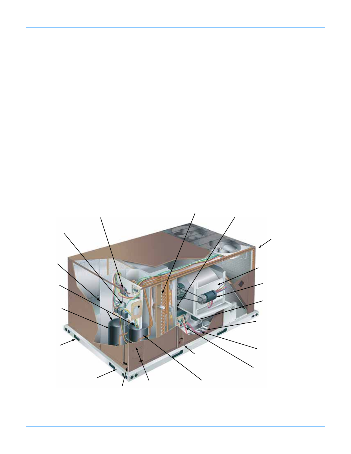
Roof curbs in eight- and
fourteen-inch heights. Roof
curbs for transitioning from
York Sunline™ footprint to
the ZF Series footprints
are also available (field
installed accessory)
Base rails w/forklift
slots (three sides)
and lifting holes
Compressor #2
access (highefficiency
compressor
w/crankcase
heater)
Dual stage
cooling for
maximum
comfort
Second model
nameplate
inside hinged
access panel
Terminal block for
hi-voltage connection
Simplicity® SE control board
w/screw connector for T-stat
wiring and network connections
Disconnect location
(optional disconnect switch)
Filter Access
(2” or 4” filter options)
Filter drier
(solid core)
Slide-out motor and
blower assembly for
easy adjustment
and service
Belt-drive
blower motor
Power ventor motor
20-gauge aluminized steel tubular
heat exchanger for
long life (stainless
steel option)
Two-stage gas
heating
to maintain
warm, comfortable
temperature
Ignition control
board for safe and
efficient operation
Compressor #1 access
(high-efficiency compressor
w/crankcase heater)
Toolless
door latch
Side entry power
and control wiring
knockouts
Slide-out drain pan
with 3/4” NPT,
female connection
ZF Series utilize Micro-Channel
Aluminum Tube/Aluminum Fin
Condenser
Table of Contents
Description . . . . . . . . . . . . . . . . . . . . . . . . . . . . . . . . . . . . . . . . . . . . . . . . . . . . . . . . . . . . . . . . . . . . . . . . . . . . . . . . . . . . . . . . . . . . 1
Table of Contents . . . . . . . . . . . . . . . . . . . . . . . . . . . . . . . . . . . . . . . . . . . . . . . . . . . . . . . . . . . . . . . . . . . . . . . . . . . . . . . . . . . . . . . 2
Component Location . . . . . . . . . . . . . . . . . . . . . . . . . . . . . . . . . . . . . . . . . . . . . . . . . . . . . . . . . . . . . . . . . . . . . . . . . . . . . . . . . . . . 2
Nomenclature . . . . . . . . . . . . . . . . . . . . . . . . . . . . . . . . . . . . . . . . . . . . . . . . . . . . . . . . . . . . . . . . . . . . . . . . . . . . . . . . . . . . . . . . . . 3
Features and Benefits . . . . . . . . . . . . . . . . . . . . . . . . . . . . . . . . . . . . . . . . . . . . . . . . . . . . . . . . . . . . . . . . . . . . . . . . . . . . . . . . . . . . 4
Guide Specifications . . . . . . . . . . . . . . . . . . . . . . . . . . . . . . . . . . . . . . . . . . . . . . . . . . . . . . . . . . . . . . . . . . . . . . . . . . . . . . . . . . . . . 9
Physical Data . . . . . . . . . . . . . . . . . . . . . . . . . . . . . . . . . . . . . . . . . . . . . . . . . . . . . . . . . . . . . . . . . . . . . . . . . . . . . . . . . . . . . . . . . . 13
Capacity Performance . . . . . . . . . . . . . . . . . . . . . . . . . . . . . . . . . . . . . . . . . . . . . . . . . . . . . . . . . . . . . . . . . . . . . . . . . . . . . . . . . . 16
Airflow Performance . . . . . . . . . . . . . . . . . . . . . . . . . . . . . . . . . . . . . . . . . . . . . . . . . . . . . . . . . . . . . . . . . . . . . . . . . . . . . . . . . . . . 28
Sound Performance . . . . . . . . . . . . . . . . . . . . . . . . . . . . . . . . . . . . . . . . . . . . . . . . . . . . . . . . . . . . . . . . . . . . . . . . . . . . . . . . . . . . 40
Electrical Data . . . . . . . . . . . . . . . . . . . . . . . . . . . . . . . . . . . . . . . . . . . . . . . . . . . . . . . . . . . . . . . . . . . . . . . . . . . . . . . . . . . . . . . . . 41
Typical Wiring Diagrams . . . . . . . . . . . . . . . . . . . . . . . . . . . . . . . . . . . . . . . . . . . . . . . . . . . . . . . . . . . . . . . . . . . . . . . . . . . . . . . . 42
Weights and Dimensions . . . . . . . . . . . . . . . . . . . . . . . . . . . . . . . . . . . . . . . . . . . . . . . . . . . . . . . . . . . . . . . . . . . . . . . . . . . . . . . . 46
Economizer Options . . . . . . . . . . . . . . . . . . . . . . . . . . . . . . . . . . . . . . . . . . . . . . . . . . . . . . . . . . . . . . . . . . . . . . . . . . . . . . . . . . . . 54
Component Location
Cooling With Gas Heat
2 Johnson Controls Unitary Products
Page 3
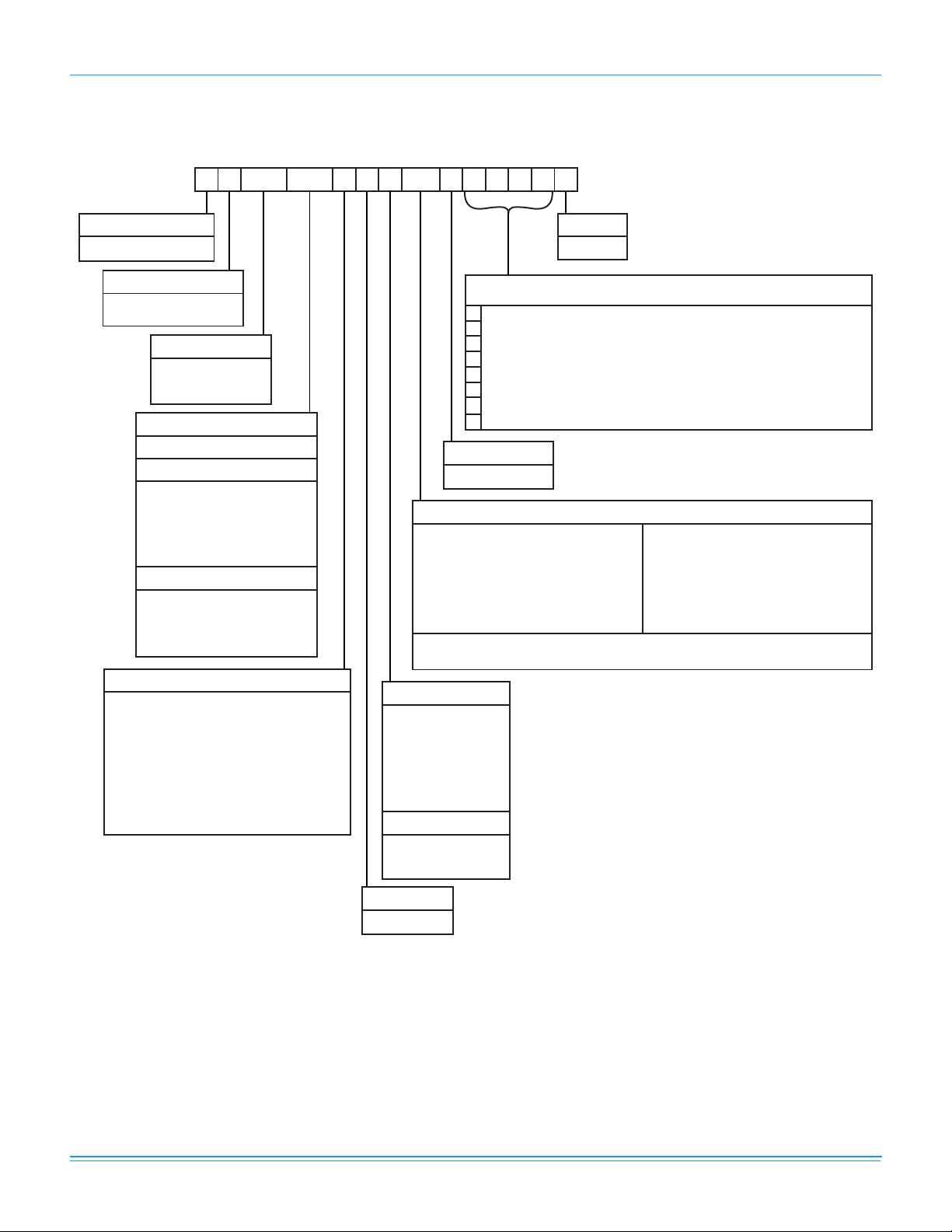
Nomenclature
Z F 090 N10 A 7 A AA 7 0 1 2 4 A
Z = A/C, Single Pkg., R410A
Product Category
7 = Seventh Generation
Product Generation
C00 = Cooling Only. No heat installed
Heat Type and Nominal Heat Capacity
N10 = 100 MBH Output Aluminized Steel
N15 = 150 MBH Output Aluminized Steel
S10 = 100 MBH Output Stainless Steel
S15 = 150 MBH Output Stainless Steel
E18 = 18 KW
E24 = 24 KW
E36 = 36 KW
E54 = 54 KW
Gas Heat Options*
Electric Heat Options*
Nominal Cooling Capacity
090 = 7.5 Ton
120 = 10.0 Ton
150 = 12.5 Ton
Product Identifier
F = 11.2 EER 7.5 & 10 Ton A/C
Voltage
7 = 380/415-3-50
Product Style
A = Style A
A = No Options Installed
Installation Options
B = Option 1
E = Option 3
F = Option 4
G = Options 1 & 3
H = Options 1 & 4
L = Options 1,3 & 4
R = Options 3 & 4
1 = Disconnect
3 = Smoke Detector S.A.
4 = Smoke Detector R.A.
Options
SS Drain Pan
Configuration Options (not required for all units)
These four digits will not be assigned until a quote is requested, or an order placed.
Honeywell Controller, DFS, APS
Simplicity®Smart Equipment w/Comm Card (BACnet, N2, Mod-Bus)
BAS Ready Unit with Belimo Economizer
Shipping Bag
Any Combination of Additional Options that Don’t Have an Option Code Pre-assigned
AA = None
AB = Phase Monitor
AC = Coil Guard
AD = Dirty Filter Switch
AE = Phase Monitor & Coil Guard
AF = Phase Monitor & Dirty Filter Switch
AG = Coil Guard & Dirty Filter Switch
AH = Phase Monitor, Coil Guard & Dirty Filter Switch
Additional Options
RC = Coil Guard & American Flag
TA = Technicoat Condenser Coil
TJ = Technicoat Evaporator Coil
TS = Technicoat Evaporator & Condenser Coils
7.5-12.5 Ton York® Model Number Nomenclature
ZZ = If desired option combination is not listed above, ZZ will be assigned and configuration options will be
located in digits 15-18.
* No Electric Heat Options for ZF090
** Only Hi Static Is Offered On ZF150
11.0 EER 12.5 Ton A/C
2" Pleated Filters, MERV 7
4" Pleated Filters, MERV 13
EA = ElectroFin Condenser Coil
EJ = ElectroFin Evaporator Coil
ES = ElectroFin Cond & Evap Coils
N20 = 200 MBH Output Aluminized Steel
S20 = 200 MBH Output Stainless Steel
* N10/S10 Not Available on ZF120/150
Airow
A = Std. Motor
D = Std. Motor/Motorized Damper (Downow Only)
H = Std Motor/Low Leak Econ/Barometric Relief (Downow
& Horizontal End Return Only)
J = Std Motor/Low Leak Econ/Power Exhaust (Downow
& Horizontal End Return Only)
N = Hi Static
R = Hi Static/Motorized Damper (Downow Only)
V = Hi Static Mtr/Low Leak Econ/Barometric Relief
(Downow & Horizontal End Return Only)
W = Hi Static Mtr/Low Leak Econ/Power Exhaust
(Downow & Horizontal End Return Only)
862075-XTG-G-0415
Johnson Controls Unitary Products 3
Page 4
862075-XTG-G-0415
Features and Benefits
Standard Features
• High Efficiency – High efficiency units reach as high as
11.2 EER. Gas/electric units have electronic spark ignition
and power vented combustion with steady state efficiencies
of 80%. These efficiencies exceed all legislated minimum
levels and provide low operating costs.
• Service Friendly – The Predator
of enhancements which improve serviceability.
The motor and blower slide out of the unit as a common
assembly. This facilitates greater access to all the indoor
airflow components, thus simplifying maintenance and
adjustment.
Service time is reduced through the use of hinged,
toolless panels. Such panels provide access to frequently
inspected components and areas, including the control
box, compressors, filters, indoor motor & blower, and the
heating section. The panels are screwed in place at the
factory to prevent access by children or other
unauthorized persons. It is recommended that the panels
be secured with screws once service is complete.
Service windows have been placed in both condenser
section walls. Rotation of the cover allows easy access to
the condenser coils for cleaning or inspection.
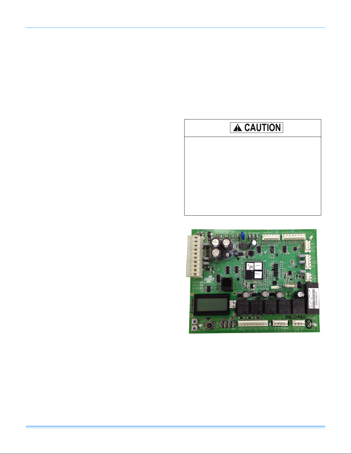
The Simplicity® SE control board provides alarm
messages to help quickly identify any faults.
All units use the same standard filter size. This
standardization removes any confusion on which filter
sizes are needed for replacement.
The non-corrosive drain pan slides out of the unit to permit
easy cleaning. The drain pan is accessed by removing the
drain pan cover plate on the rear of the unit. Once the plate is
removed, the drain pan slides out through the rear of the unit.
®
All Predator
units have a second model nameplate
located inside the control access door. This is to prevent
deterioration of the nameplate through weathering.
• Coil Technology – ZF condensers utilize Micro-Channel
“all aluminum” condensers which provide improved heat
transfer capabilities and reduced charge volumes.
• Environmentally Aware – For improved Indoor Air
Quality, a combination of foil faced and elastometric
rubber insulation is used exclusively throughout the units.
• Balanced Heating – The Predator
Heating Comfort” with a balance between 1
gas heating. The first stage of a gas heat Predator
provides 60% of the heating capacity. Balanced heating
allows the unit to better maintain desired temperatures.
• Convertible Airflow Design – The side duct openings
are covered when they leave the factory. If a side supply/
return is desired, the installer simply removes the two side
duct covers from the outside of the unit and installs them
over the down shot openings. No panel cutting is required.
Convertible airflow design allows maximum field flexibility
and minimum inventory.
• System Protection - Suction line freezestats are supplied
on all units to protect against loss of charge and coil frosting
when the economizer operates at low outdoor air
®
incorporates a number
®
offers “Ultimate
st
and 2nd stage
®
temperatures while the compressors are running. Every unit
has solid-core liquid line filter-driers and high and lowpressure switches. Internal compressor protection is
standard on all compressors. Crankcase heaters are
standard on reciprocating compressors. Scroll compressors
do not require crankcase heaters. Phase Monitors are
standard on units with scroll compressors. This accessory
monitors the incoming power to the unit and protects the
unit from phase loss and reversed phase rotation.
• Advanced Controls - Simplicity® SE control boards have
standardized a number of features previously available only
as options or by utilizing additional controls.
The Simplicity® SE control board used in this
product will effectively operate the cooling system
down to 0°F when this product is applied in a comfort
cooling application for people. An economizer is
typically included in this type of application. When
applying this product for process cooling applications
(computer rooms, switchgear, etc.), please
reference applications bulletin AE-011-07 or call the
applications department for Unitary Products @ 1877-UPG-SERV for guidance. Additional
accessories may be needed for stable operation at
temperatures below 30°F.
unit
• Units will come with the new state of the art Simplicity
SE (Smart Equipment) control system. The new unit
control incorporates the best of the already proven
Simplicity™ unitary controls and creates a more robust,
intelligent control. The goal of this control is to utilize
cutting edge technology making the equipment easier to
install, operate, and service. All units are Factory
commissioned, configured, and run tested.
• Versatile - The Simplicity SE control can be configured to
use with a standard thermostat (easy to connect screw
terminals), A zone sensor, or can be setup to
4 Johnson Controls Unitary Products
Page 5

862075-XTG-G-0415
communicate with multiple BAS communication protocols
to integrate with building automation systems.
• Reduce field installed complexity - Each unit will comes
equipped with factory installed supply air, return air, and
outdoor air temperature sensors providing key
temperature readings thus reduce field installed
complexity.
• On-board USB Port - The new control comes with a long
list of features including data logging, current and
previous system faults and software update capabilities
using the on board USB port and common flash drive.
Energy use monitoring capabilities allow custom tailoring
to allow a system to work more efficiently at all times and
occupancy levels. Self test and start-up reports also
available from the board VIA the USB port.
• Embedded LCD Display - The board has a easy to read,
built-in LCD display and easy to use navigation joystick
and buttons allowing the user to quickly navigate the
menus displaying unit status, options, current function,
supply, return and outdoor temperatures, fault codes and
other information.
• Safety Monitoring - The control monitors the outdoor,
supply, and return air temperatures and the high and low
pressure switch status on the independent refrigerant
circuits. On units with heating the gas valve and high
temperature limit switches are monitored on gas and
electric heating units. The control also monitors the
voltage supplied to the unit and will protect the unit if low
voltage due to a brown out, or other electrical issue
occurs.
• Low Ambient - An integrated low-ambient control allows
units to operate in the cooling mode down to 0°F outdoor
ambient without additional components or intervention.
Optionally, the control board can be programmed to
lockout the compressors when the outdoor air
temperature is low or when free cooling is available.
• Anti-Short Cycle Protection - To aid compressor life, an
anti- short cycle delay is incorporated into the standard
control. Compressor reliability is further ensured by
programmable minimum run times. For testing, the antishort cycle delay can be temporarily overridden with the
push of a button.
• Fan Delays - Fan on and fan off delays are fully
programmable. Furthermore, the heating and cooling fan
delay times are independent of one another. All units are
programmed with default values based upon their
configuration of cooling and/or heating capacity.
• Nuisance Trip Protection and Three Strikes - To
prevent nuisance calls, the control board uses a three
times, you're out philosophy. The high, low-pressure
switch, anti-freeze protection, low voltage or heating high
limit must trip three times within two hours before the unit
control board will lock out the associated compressor.An
alarm message will be displayed on the LCD screen.
• Lead-Lag - An integrated Lead-Lag option allows equal
run time hours on all compressors, thereby extending the
life of all compressors. This option is selectable on the unit
control board.
• Low Limit Control (LLC) - To prevent the supply air from
dropping below a specified set point, when there is a
demand for cooling during cold outside conditions.
(Programmable Set point)
• Reliable – From the beginning – All units undergo
computer automated testing before they leave the factory.
Units are tested for refrigerant charge and pressure, unit
amperage, and 100% functionality. For the long term – All
Predator
®
units are painted with a long lasting, powder
paint that stands up over the life of the unit. The paint
used has been proven by a 1000 hour salt spray test.
• Flexible Placement – All models and configurations
share the same cabinet/footprint and thus the same roof
curb. You have the flexibility to set one curb and choose
the correct tonnage size and heating option after the
internal loads have been determined.
®
To further simplify planning and installation, Predator
ZF
cabinets are designed to fit your roof. With the optional
roof curb, the unit ductwork is designed to fit around 24”
on-center joists or between 48” on-center joists.
The drain pan can be rotated to drain to either the front or
the rear of the unit. Additionally, the drain pan can be
fitted to drain through the roof curb. As it is sometimes
difficult to have a level installation, the drain pan features
a generous slope to ensure proper drainage.
• Full Perimeter Base Rails – The permanently attached
base rails provide a solid foundation for the entire unit and
protect the unit during shipment. The rails offer forklift
access from 3 sides, and rigging holes are available so that
an overhead crane can be used to place the units on a roof.
• Easy Installation – Gas and electric utility knockouts are
supplied in the unit underside as well as the side of the unit.
A clearly identified location is provided to mount a field
supplied electrical disconnect switch. Utility connections can
be made quickly and with a minimum amount of field labor.
All units are shipped with 2” throw-away filters installed.
• Wide Range of Indoor Airflows – All indoor fan moto rs
are belt-drive type providing maximum flexibility to handle
most airflow requirements. For high static applications,
factory installed alternate indoor fan motors are available.
With the optional indoor fan motor, all units can supply
nominal airflow at a minimum of 1.5” ESP.
• Warranty - All models include a 1-year limited warranty
on the complete unit. Compressors and electric heater
elements each carry a 5-year warranty. Aluminized steel
and stainless steel tubular heat exchangers carry a 10year warranty.
Factory Installed Options
YORK® offers several equipment options factory installed, for
the Predator
• Optional Factory Installed Economizers - Predator units
®
line.
offer a variety of optional factory installed economizers
with low leak dampers. The outdoor air enthal py se nsor
enables economizer operation if the outdoor enthalpy is
less than the setpoint of the economizer logic module. See
economizer options section to determine the correct
economizer for your application.
Johnson Controls Unitary Products 5
Page 6
862075-XTG-G-0415
• Down flow / End Return Economizers (with barometric
relief and fresh air hood) - All units offer a variety of
optional factory installed down flow eco no m ize rs that are
shipped, installed and wired with low leak dampers
designed to meet ASHRAE 90.1-2010, AMCA 511 Class
1A damper, and the International Energy Con se rvati on
Code (IECC) certification requir emen ts by a c hi eving
leakage rates of 3 cfm/sq. ft. at 1" of static pressure. Each
economizer goes through a rigorous 60,000 cycle test. Dry
bulb, single enthalpy, and dual enthalpy (with field installed
kit) can be selected. The economizer has spring return,
fully modulating damper actuators and is capabl e o f
introducing up to 100% outdoor air. As the outdoor ai r
intake dampers open, the return air dampers close. The
changeover from mechanical refrigeration to economizer
operation is regulated by the outdoor ai r dry bulb
temperature or the outdoor air enthalpy input. The optional
(field installed) single or dual ent hal py ki ts pro vi de
additional inputs to monitor outdoor ai r/ or re turn ai r
humidity and temperature for true enthalpy contro l. The
installer needs only to assemble the outdoor air hood,
attach the enthalpy control the hood and mount th e h oo d
to the unit (Hood and control are provided).
• Power Exhaust - This factory option allows down flow or
horizontal end return economizer operation. The power
exhaust must be removed from the unit and mounted
in the horizontal end return duct work when applying
the product in the horizontal, end return
configuration.
• Motorized Outdoor Air Damper - The motorized outdoor
air damper includes a slide-in/plug-in damper assembly
with an outdoor air hood and filters. The outdoor air
dampers open to the preset position when the indoor fan
motor is energized. The damper has a range of 0% to
100% outdoor air entry. Factory installed option or field
installed accessory.
• Alternate Indoor Blower Motor - For applications with
high static restrictions, units are offered with optional
indoor motors that provide higher static output and/or
higher airflow, depending upon the installer’s needs.
• Aluminized Steel Gas Heat Exchanger - For
applications in non-corrosive environments.
• Stainless Steel Gas Heat Exchanger - For applications
in corrosive environments, this option provides a full
stainless steel heat exchanger assembly.
• Stainless Steel Drain Pan - An optional rust-proof
stainless steel drain pan is available to provide years of
trouble-free operation in corrosive environments.
• Electric Heaters (10 & 12.5 Ton Only) - The electric
heaters range from 18KW to 54kW and are available in all
the voltage options of the base units. All heaters are dual
staged. All heaters are intended for single point power
supply.
• Disconnect Switch - For gas heat units and cooling units
with electric heat, a HACR breaker sized to th e unit is
provided. For cooling only units, a switch sized to the
largest electric heat available for the particular unit is
provided. Factory installed optio n onl y.
• Smoke Detectors - The smoke detectors stop operation
of the unit by interrupting power to the control board if
smoke is detected within the air compartment. Available
for both the supply and/or return air configurations.
• Filters – 2” Pleated MERV 7 or 4” Pleated MERV 13 are
available to meet LEED requirements. A 2” Throwaway is
shipped as standard.
Factory-installed smoke detectors may be subjected to
extreme temperatures during "off" times due to outside air
infiltration. These smoke detectors have an operational
range of -4 °F to 158°F. Smoke detectors installed in areas
that could be outside this range will have to be relocated to
prevent false alarms.
• Phase Monitors - Designed to prevent unit damage. The
phase monitor will shut the unit down in an out-of phase
condition. (Standard on units with Scroll Compressors.)
• Coil Guard - Customers can purchase a coil guard kit to
protect the condenser coil from damage. Additionally, this
kit stops animals and foreign objects from entering the
space between the inner condenser coil and the main
cabinet. This is not a hail guard kit.
• Dirty Filter Switch - This kit includes a differential
pressure switch that energizes the fault light on the unit
thermostat, indicating that there is an abnormally high
pressure drop across the filters. Factory installed option or
field installed accessory.
• Technicoat Condenser Coils - The condenser coils are
coated with a phenolic coating for protection against
corrosion due to harsh environments.
• Technicoat Evaporator Coil - The evaporator coils are
coated with a phenolic coating for protection against
corrosion due to harsh environments.
• ElectroFin® E-coat Condenser Coils - The condenser
coils are coated with an epoxy polymer coating to protect
against corrosion.
• ElectroFin® E-coat Evaporator Coils - The evaporator
coils are coated with an epoxy polymer coating to protect
against corrosion.
Control Options
• Simplicity® SE with Communication Option Control The York® Simplicity® SE with Communication Option
Control is factory installed. It includes all the features of
the Simplicity® SE control with an additional gateway to
BACnet MS/TP (programmable to Modbus or N2
protocols).
• Novar® BAS Control - The Novar® building automation
system controller is factory installed. Incudes supply air
sensor, return air sensor, dirty filter indicator switch, and
air proving switch.
• CPC BAS Control - The Computer Process Controls
Model 810-3060 ARTC Advanced Rooftop building
automation system controller is factory installed. Includes
6 Johnson Controls Unitary Products
Page 7

862075-XTG-G-0415
supply air sensor, return air sensor, dirty filter indicator
switch and air proving switch.
• Honeywell BAS Control - The Honeywell W7750C
building automation system controller is factory installed.
Includes air supply sensor, return air sensor, dirty filter
indicator switch, and air proving switch.
Field Installed Accessories
YORK® offers several equipment accessories for field
installation, for the Predator
• Down flow and End Return Economizers (with fresh air
hood and barometric relief) - All units offer a variety of
optional factory installed down flow economizers that are
shipped, installed and wired with low leak dampers designed
to meet ASHRAE 90.1-2010, AMCA 511 Class 1A damper,
and the International Energy Conservation Code (IECC)
certification requirements by achieving leakage rates of 3
cfm/sq. ft. at 1" of static pressure. Each economizer goes
through a rigorous 60,000 cycle test. Dry bulb, single
enthalpy, and dual enthalpy (with field installed kit) can be
selected. The economizer has spring return, fully modulating
damper actuators and is capable of introducing up to 100%
outdoor air. As the outdoor air intake dampers open, the
return air dampers close. The changeover from mechanical
refrigeration to economizer operation is regulated by the
outdoor air dry bulb temperature or the outdoor air enthalpy
input. The dual enthalpy kit provides a second input used to
monitor the return air (field installed). The installer needs only
to assemble the outdoor air hood, attach the enthalpy control
the hood and mount the hood to the unit (Hood and control
are provided).
• Single or Dual Enthalpy Control, Accessories - These
kits contain the required components to convert a dry bulb
economizer to a single enthalpy and/or dual enthalpy
economizer.
• Barometric Relief Damper - Zero to 100% capacity
barometric relief dampers for use with horizontal flow, or
field installed slab economizers.
• Power Exhaust - This accessory installs in the unit with a
down flow economizer. Power exhaust plugs into the
connector in the unit bulkhead. You must purchase
1EH0408 barometric relief when applying to a
horizontal flow application.
• Manual Outdoor Air Damper - Like the motorized outdoor
air damper, each manual outdoor air damper includes a
slide-in damper assembly with an outdoor air hood and
filters. Customers have a choice of dampers with ranges of
0% to 100% or 0% to 35% outdoor air entry.
• Motorized Outdoor Air Damper - The motorized outdoor
air damper includes a slide-in/plug-in damper assembly with
an outdoor air hood and filters. The outdoor air dampers
open to the preset position when the indoor fan motor is
energized. The damper has a range of 0% to 100% outdoor
air entry. Factory installed option or field installed accessory.
• Smoke Detectors - The smoke detectors stop operation
of the unit by interrupting power to the control board if
smoke is detected within the air compartment.
®
line.
Sensor - Senses CO2 levels and automatically
• CO
2
overrides the economizer when levels rise above the
preset limits.
• Dirty Filter Switch - This kit includes a differential
pressure switch that energizes the fault light on the unit
thermostat, indicating that there is an abnormally high
pressure drop across the filters.
• Coil Guard - Field installed decorative wire coil guard.
• Hail Guard - This kit includes a sloped hood which installs
over the outside condenser coil and prevents damage to
the coil fins from hail strikes. Field installed accessory only.
• Flue Exhaust Extension Kit - In locations with wind or
weather conditions which may interfere with proper
exhausting of furnace combustion products, this kit can be
installed to prevent the flue exhaust from entering nearby
fresh air intakes.
• -60°F Gas Heat Kit - For installations which require gas
heat units to perform in low ambient temperatures, a gas
section heating kit is available. This kit provides electric
heat in the gas heat controls section to ensure the gas
valve and controls will continue to function properly at
extremely low temperatures.
• Gas Heat High Altitude Kit - This kit converts a gas heat
unit to operate at high altitudes, 2,000 to 6,000 feet.
Conversion kits are available for natural gas and propane.
• Gas Heat Propane Conversion Kit - This kit converts a
gas-fired heater from natural gas to propane. It contains the
main burner orifices and gas valve replacement springs.
• Gas Piping Kit - Contains pipe nipples, fittings and gas cock
required for gas supply connection with external shut off.
• Electric Heaters (10 & 12.5 Ton Only) - The electric
heaters range from 18 kW to 54kW.
All heaters are dual staged. Cooling units include an
adapter panel for easy installation of the electric heaters.
Necessary hardware and connectors are included with the
heaters. All heaters are intended for single point power
supply.
• Low Limit / Compressor Lockout Kit
• Compressor Lockout (CLO): To prevent mechanical
(compressorized) operation of the unit during cold
outdoor conditions where there is a risk of returning
liquid refrigerant back to the compressors.
• Low Limit Control (LLC): To prevent the supply air
from dropping below a specified setpoint by utilizing the
units first stage heating means when there is a demand
for cooling during cold outside conditions.
• Metal Frame Filter Kit - Metal frame with polyester filter
medium.
• Permanent Filters - Permanent filters are available.
• Roof Curbs - The roof curbs have insulated decks and are
shipped disassembled The roof curbs are available in 8” and
14” heights. For applications with security concerns, burglar
bars are available for the duct openings of the roof curbs.
• Roof Curb Transition - Single Piece Adapter (10” High) Roof curbs for transitioning from Sunline™ units to
Predator
®
units. Fits 7.5 to 12.5 Sunline™ roof curbs only.
Johnson Controls Unitary Products 7
Page 8

862075-XTG-G-0415
• Burglar Bars - Mount in the supply and return openings
to prevent entry into the duct work.
• Thermostat - The units are designed to operate with 24-
units (with or without an economizer) operate with twostage heat/two-stage cool or two-stage cooling only
thermostats, depending upon unit configuration.
volt electronic and electro-mechanical thermostats. All
Accessories
Field Installed Accessories - Non-Electrical
MODEL VOLTAGE DESCRIPTION WHERE USED
1BD0408 All Burglar Bars, Downflow All Cabinets
1CG0419 All Coil Guard (Electric / Electric Models), 50” Tall Standard Cabinets
1CG0420 All Coil Guard (Gas / Electric Models), 50" Tall Standard Cabinets
1CG0427 All Coil Guard (Electric / Electric Models), 42” Tall Cabinets
1CG0428 All Coil Guard (Gas / Electric Models), 42" Tall Cabinets
All Tall (50") Standard Cabinets, (Excludes 12.5T "V"
1HG0411 All Hail Guard Kit
1HG0415 All Hail Guard Kit All Short (42") Standard Cabinets
1FE0411 All Flue Exhaust Extension Kit All Cabinets
1FF0414 All 2" only Metal Filter Frame Kit All Tall 50" Cabinets
1FF0415 All 2" only Metal Filter Frame Kit All Tall 42" Cabinets
1FL0402 All Permanent 2" only Filter Kit Includes (4) Four Filters) All Tall 50" Cabinets
1FL0423 All Permanent 2" only Filter Kit (Includes (4) four Filters) All Tall 42" Cabinets
1GP0405 All Gas Piping Kit All Cabinets
1HA0442 All High Altitude Kit for Natural Gas All 7 1/2 - 12T Cabinets
1HA0443 All High Altitude Kit for Propane All 7 1/2 - 12T Cabinets
1NP0442 All Propane Conversion Kit All 6 - 12T Cabinets
1RC0470 All Roof Curb, 8" Height All Cabinets
1RC0471 All Roof Curb, 14" Height All Cabinets
Roof Curb, Transition (7.5 T thru 12.5T Sunline to
1RC0472 All
1WC0412 All
Predator 3- 12T) All Cabinets
Wooden Crate for extra protection during shipping and
handling
cabinets)
Standard Cabinets Only (not applicable to units 119" in
length)
Field Installed Accessories - Electric Heat
MODEL VOLTAGE DESCRIPTION WHERE USED
2TP04521850 380/415-3-50 18kW Electric Heat All 50" Cabinet 10 Ton Models
2TP04522450 380/415-3-50 24kW Electric Heat All 50" Cabinet 10 and 12.5 Ton Models
2TP04523650 380/415-3-50 36kW Electric Heat All 50" Cabinet 10 and 12.5 Ton Models
2TP04525450 380/415-3-50 54kW Electric Heat All 50" Cabinet 10 and 12.5 Ton Models
No factory or field installed electric heater available for 42” Cabinet ZF090
*Note:
8 Johnson Controls Unitary Products
Page 9

862075-XTG-G-0415
Accessories (Continued)
Field Installed Accessories - Fresh Air
MODEL VOLTAGE DESCRIPTION WHERE USED
1FA0413 All Manual Outside Air Damper 0-35%, Downflow All Cabinets
1FA0414 All Manual Outside Air Damper 0-100%, Downflow All Cabinets
1EH0408 All
2EC0401 All Single Enthalpy Control All Cabinets
2EC0402 All Dual Enthalpy Control (Includes 2 Sensors) All Cabinets
2EE04707624 All
2EE04707424 All
2EE04706924 All Horizontal Economizer without Barometric Relief All Cabinets
2MD04703824 All Motorized Damper, Downflow without Barometric Relief All Cabinets
2MD04703924 All
2PE04704706* 230 Power Exhaust 230V Downflow or Horizontal All Cabinets
2PE04704746* 460 Power Exhaust 460V Downflow or Horizontal All Cabinets
2PE04704758* 575 Power Exhaust 575V Downflow or Horizontal All Cabinets
* Must be installed in return Duct on Horizontal Applications and a 1EH0408 is required. Approved for operation on 50Hz
Barometric Relief Kit for Power Exhaust, Horizontal
Application
Economizer for Downflow, End Return Horizontal, or
ERV Applications. Includes FA Hood, Exhaust Hood w/
Baro Relief
Economizer for Downflow, End Return Horizontal, or
ERV Applications. Includes FA Hood, Exhaust Hood w/
Baro Relief
Motorized Damper, Horizontal without Barometric
Relief
Field Installed Accessories - Controls
MODEL VOLTAGE DESCRIPTION WHERE USED
2AP0401 All Air Proving Switch All Units
2AQ04700324 All CO2 Space Accessory All Units
2AQ04700424 All CO2 Unit Accessory All Units
2DF0402 All Dirty Air Switch All Units
2SH0401 All
2SD04700824 All Smoke Detector for Supply All Gen 5 units and greater with 2" & 4" Filters
2SD04700924 All Smoke Detector for Return All Gen 5 units and greater with 2" & 4" Filters
2SD04701024 All Smoke Detector for Supply and Return All Gen 5 units and greater with 2" & 4" Filters
S1-YKMAP1810-0P
S1-MP-PRTKIT0P
All
All
Wall Mounted humidity sensor-For use with MagnaDry
Reheat or space humidity input to Simplicity SE board.
MAP (Mobile Access Portal) Gateway- For use with
Simplicity SE Control.
MAP (Multiple Access Portal) Gateway KitReplacement MAP gateway protective case, lanyard
and communication cable. Use only to replace worn or
damaged components.
All Cabinets
All 50" Cabinets
All 42" Cabinets
All Cabinets
All Cabinets
All Units
All Units
Field Installed Accessories - Electrical
MODEL VOLTAGE DESCRIPTION WHERE USED
2BC04700106 230 Gas heat kit, -60ºF All Units
2BC04700151 460 Gas heat kit, -60ºF All Units
2BC04700154 575 Gas heat kit, -60ºF All Units
2LA04704632 All Low Ambient Kit All 3 - 10T units (excludes 12.5T "V" cabinets)
Guide Specifications
GENERAL
Units shall be manufactured by York International Unitary
Products in an ISO 9001 certified facility. YORK® Predator
units are convertible single packages with a common footprint
cabinet and common roof curb for all 7-1/2 through 12-1/2 ton
models. All units have two compressors with independent R410A refrigeration circuits to provide 2 stages of cooling. The
units were designed for light commercial applications and can
be easily installed on a roof curb, slab, or frame. All Predator
units are self-contained and assembled on rigid full perimeter
base rails allowing for 3-way forklift access and overhead
rigging. Every unit is completely charged with R-410A, wired,
®
piped, and tested at the factory to provide a quick and easy
field installation. All units are convertible between side and
down airflow. Independent economizer designs are used on
side and down discharge applications, as well as all tonnage
sizes. Predator
®
units are available in the following
configurations: cooling only, cooling with electric heat, cooling
with gas heat, heat pump, and heat pump with electric heat.
Electric heaters are available as factory-installed options or
field-installed accessories.
®
DESCRIPTION
Units shall be factory assembled, single package, (Elec/Elec, Gas/
Elec), designed for outdoor installation. They shall have built in
Johnson Controls Unitary Products 9
Page 10

862075-XTG-G-0415
field convertible duct connections for down discharge supply/return
or horizontal discharge supply/return and be available with factory
installed options or field installed accessories. The units shall be
factory wired, piped and charged with R-410A refrigerant and
factory tested prior to shipment. All unit wiring shall be both
numbered and color coded. The cooling performance shall be
rated in accordance with DOE and AHRI test procedures and
MEW-2010.
UNIT CABINET
Unit cabinet shall be constructed of galvanized steel with
exterior surfaces coated with a non-chalking, powder paint
finish, certified at 1000 hour salt spray test per ASTM-B117
standards. Indoor blower sections shall be insulated with up to
1” thick insulation coated on the airside. Either aluminum foil
faced or elastometric rubber insulation shall be used in the
unit’s compartments and be fastened to prevent insulation from
entering the air stream. Cabinet doors shall be hinged with
toolless access for easy servicing and maintenance. Full
perimeter base rails shall be provided to assure reliable transit
of equipment, overhead rigging, fork truck access and proper
sealing on roof curb applications. Disposable 2” filters shall be
furnished as standard and be accessible through hinged access
door. Fan performance measuring ports shall be provided on
the outside of the cabinet to allow accurate air measurements
of evaporator fan performance without removing panels or
creating bypass of the coils. Condensate pan shall be slide out
design, constructed of a non corrosive material, internally
sloped and conforming to ASHRAE 62-B9 standards.
Condensate connection shall be a minimum of ¾” I.D. female
and be rigid mount connection.
INDOOR (EVAPORATOR) FAN ASSEMBLY
Fan shall be a belt drive assembly and include an adjustable
pitch motor pulley. Job site selected brake horsepower shall not
exceed the motors nameplate horsepower rating plus the service factor. Units shall be designed to operate within the service
factor. Fan wheel shall be double inlet type with forward curve
blades, dynamically balanced to operate smoothly throughout
the entire range of operation. Airflow design shall be constant
volume. Bearings shall be sealed and permanently lubricated
for longer life and no maintenance. Entire blower assembly and
motor shall be slide out design.
OUTDOOR (CONDENSER) FAN ASSEMBLY
The outdoor fans shall be of the direct drive type, discharge air
vertically, have aluminum blades riveted to corrosion resistant
steel spider brackets and shall be dynamically balanced for
smooth operation. The outdoor fan motors shall have permanently
lubricated bearings internally protected against overload
conditions and staged independently. A cleaning window shall be
provided on two sides of the units for coil cleaning.
REFRIGERANT COMPONENTS
Compressors:
a. Shall be fully hermetic type, direct drive, internally
protected with internal high-pressure relief and over
temperature protection. The hermetic motor shall be
suction gas cooled and have a voltage range of + or –
10% of the unit nameplate voltage.
b. Shall have internal spring isolation and sound muffling to
minimize vibration and noise, and be externally isolated
on a dedicated, independent mounting.
Coils:
a. Evaporator coils shall have aluminum plate fins
mechanically bonded to seamless internally enhanced
copper tubes with all joints brazed. Special Phenolic
coating shall be available as a factory option.
b. Evaporator coils shall be of the direct expansion, draw-
thru design.
c. Condenser coils shall have Micro-Channel aluminum
tube, aluminum fins.
d. Condenser coils shall be of the draw-thru design.
Refrigerant Circuit and Refrigerant Safety Components shall
include:
a. Independent thermally operated expansion devices.
b. Solid core filter drier/strainer to eliminate any moisture or
foreign matter.
c. Accessible service gage connections on both suction
and discharge lines to charge, evacuate, and measure
refrigerant pressure during any necessary servicing or
troubleshooting, without losing charge.
d. The unit shall have two independent refrigerant circuits,
equally split in 50% capacity increments.
Unit Controls:
a. Unit shall be complete with self-contained low-voltage
control circuit protected by a resettable circuit breaker on
the 24-volt transformer side.
b. Unit shall incorporate a lockout circuit which provides
reset capability at the space thermostat or base unit
should any of the following standard safety devices trip
and shut off compressor:
c. Loss-of-charge/Low-pressure switch.
• High-pressure switch.
• Freeze-protection thermostat, evaporator coil. If any of
the above safety devices trip, an LED (light-emitting
diode) indicator shall flash a diagnostic code that
indicates which safety switch has tripped.
d. Unit shall incorporate “AUTO RESET” compressor over
temperature, over current protection.
e. Unit shall operate with conventional thermostat designs
and have a low voltage terminal strip for easy hook-up.
f. Unit control board shall have on-board diagnostics and
fault code display.
g. Standard controls shall include anti-short cycle and low
voltage protection, and permit cooling operation down to
0 ºF.
10 Johnson Controls Unitary Products
Page 11

862075-XTG-G-0415
h. Control board shall monitor each refrigerant safety switch
independently.
i. Control board shall retain last 5 fault codes in non-
volatile memory, which will not be lost in the event of a
power loss.
GAS HEATING SECTION (IF EQUIPPED)
Heat exchanger and exhaust system shall be constructed of
aluminized steel and shall be designed with induced draft combustion with post purge logic, energy saving direct spark ignition, and redundant main gas valve. The heat exchanger shall
be of the tubular type, constructed of T1-40 aluminized steel for
corrosion resistance and allowing minimum mixed air entering
temperature of 40 ºF. Burners shal l be of the in-shot type, constructed of aluminum-coated steel. All gas piping shall enter the
unit cabinet at a single location, through either the side or bottom, without any field modifications. An integrated control board
shall provide timed control of evaporator fan functioning and
burner ignition. Heating section shall be provided with the following minimum protection:
a. Primary and auxiliary high-temperature limit switches.
b. Induced draft pressure sensor.
c. Flame roll out switch (manual reset).
d. Flame proving controls.
e. All two stage units shall have two independent stages of
capacity (60% 1
st
stage, 100% 2nd stage).
ELECTRIC HEATING SECTION (IF EQUIPPED)
FACTORY INSTALLED OPTIONAL OUTDOOR AIR (Shall be
made available by either/or):
• DRY BULB AUTOMATIC ECONOMIZER - Outdoor and
return air dampers that are interlocked and positioned by
a fully-modulating, spring-return damper actuator. The
maximum leakage rate for the outdoor air intake dampers
shall be designed to meet ASHRAE 90.1-2010, AMCA
511 Class 1A damper, and the International Energy
Conservation Code (IECC) certification requirements by
achieving leakage rates of 3 cfm/sq. ft. at 1" of static
pressure. Changeover from compressor to economizer
operation shall be provided by an integral electronic
enthalpy control that feeds input into the basic module.
The outdoor intake opening shall be covered with a rain
hood that matches the exterior of the unit. Water
eliminator/filters shall be provided.
• MOTORIZED OUTDOOR AIR DAMPERS – Outdoor and
return air dampers that are interlocked and positioned by
a 2-position, spring-return damper actuator. The
maximum leakage rate for the outdoor air intake dampers
shall not exceed 2% when dampers are fully closed and
operating against a pressure differential of 0.5 IWG. A
unit-mounted potentiometer shall be provided to adjust
the outdoor and return air damper assembly to take in the
design CFM of outdoor air to meet the ventilation
requirements of the conditioned space during normal
operation. Whenever the indoor fan motor is energized,
the dampers open up to one of two pre-selected positions
– regardless of the outdoor air enthalpy. Dampers return
to the fully closed position when the indoor fan motor is
de-energized. Dampers shall fully close on power loss.
An electric heating section, with nickel chromium elements,
shall be provided in a range of 18 thru 54 KW, offering two
states of capacity all sizes. The heating section shall have a primary limit control(s) (automatic reset) to prevent the heating
element system from operating at an excessive temperature.
The Heating Section assembly shall slide out of the unit for
easy maintenance and service. Units with Electric Heating Sections shall be wired for a single point power supply with branch
circuit fusing (where required).
UNIT OPERATING CHARACTERISTICS
Unit shall be capable of starting and running at 125 ºF outdoor
temperature, exceeding maximum load criteria of AHRI Standard 340/360. The compressor, with standard controls, shall be
capable of operation down to 0 ºF outdoor temperature. Unit
shall be provided with fan time delay to prevent cold air delivery
before heat exchanger warms up. (Gas heat only)
ELECTRICAL REQUIREMENTS - All unit power wiring shall
enter unit cabinet at a single factory provided location and be
capable of side or bottom entry to minimize roof penetrations
and avoid unit field modifications. Separate side and bottom
openings shall be provided for the control wiring.
ST ANDARD LIMITED WARRANTIES - Compressor – 5 Years,
Heat Exchanger – 10 Years, Elect. Heat Elem. – 5 Years,
Parts – 1 Year
ADDITIONAL FACTORY INSTALLED OPTIONS
• ALTERNATE INDOOR BLOWER MOTOR – For
applications with high restrictions, units are available with
optional indoor blower motors that provide higher static
output and/or higher airflow.
• ELECTRIC HEAT (10 & 12.5 Ton Only) - Electric Heaters
range from 18 kW to 54 kW and are available in all the
voltage options of the base unit.
• PHASE MONITOR - Designed to prevent damage in outof-phase condition.
• COIL GUARD - Designed to prevent condenser coil
damage.
• BAS CONTROLS - Include supply air sensor, return air
sensor, dirty filter indicator and air proving switch.
• DIRTY FILTER SWITCH – This kit includes a differential
pressure switch that energizes the fault light on the unit
thermostat, indicating that there is an abnormally highpressure drop across the filters.
• BREAKER – An HACR breaker can be factory installed
on gas heat units or cooling units with electric heat.
• DISCONNECT SWITCH - A disconnect can be factory
installed on a cooling only units sized for the largest
electric heat available.
Johnson Controls Unitary Products 11
Page 12

862075-XTG-G-0415
• STAINLESS STEEL HEAT EXCHANGER – For
applications in a corrosive environment, this option
provides a full stainless steel heat exchanger assembly.
• SMOKE DETECTOR – A smoke detector can be factory
mounted and wired in the supply and/or return air
compartments.
OTHER PRE-ENGINEERED ACCESSORIES AVAILABLE
• ROOF CURB - 14” and 8” high, full perimeter knockdown
curb, with hinged design for quick assembly.
• BAROMETRIC RELIEF DAMPER – (Unit mounted –
Downflow, Duct Mounted – Horizontal) – Contains a rain
hood, air inlet screen, exhaust damper and mounting
hardware. Used to relieve internal air pressure through
the unit during economizer operation.
• PROPANE CONVERSION KIT – Contains new orifices
and gas valve springs to convert from natural to L.P. gas.
• 60ºF GAS HEAT KIT – Provides an electric heat kit for the
gas compartment for use in extreme low ambient
conditions.
• ECONOMIZER (Downflow and Horizontal flow)
• POWER EXHAUST – (Unit mount – Downflow, Duct
mount – Horizontal flow)
• DUAL ENTHALPY KIT - Provides a second input to
economizer to monitor return air.
12 Johnson Controls Unitary Products
Page 13
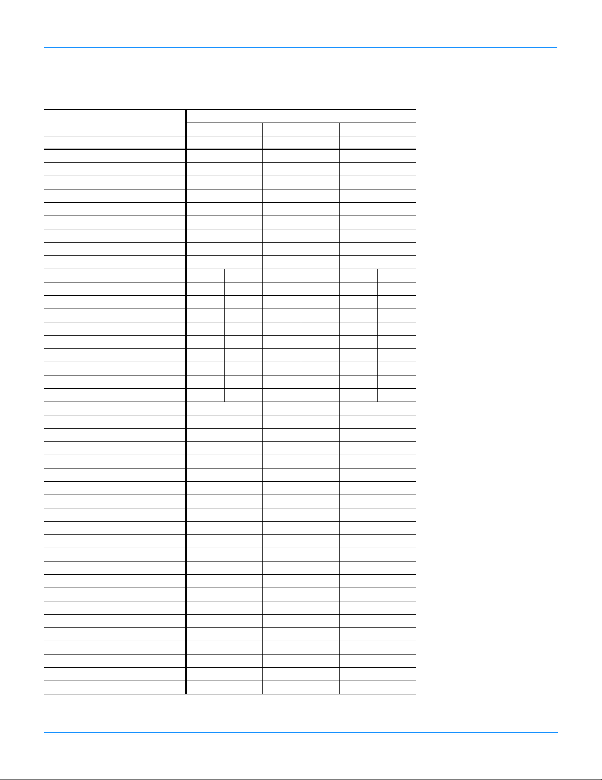
Physical Data
ZF090-150 Physical Data
Component
ZF090 ZF120 ZF150
Nominal Tonnage 7.5 10 12.5
Gross Capacity @ AHRI A point (Mbh) 88200 115300 151500
EER 11.2 11.2 11.0
Nominal CFM 3000 4000 5000
System power (KW) 7.21 10.05 12.7
Refrigerant type R-410A R-410A R-410A
Refrigerant charge (lb-oz)
System 1 4-12 7-12 8-3
System 2 4-12 7-8 8-10
AHRI HEATING PERFORMANCE
Heating model 10 15 15 20 15 20
Heat input (K Btu) 120 180 180 240 180 240
Heat output (K Btu) 96 144 144 192 144 192
AFUE % -----Steady state efficiency (%) 80 80 80 80 80 80
No. burners 466868
No. stages 2
1
1
2
Temperature Rise Range (ºF) 15-45 30-60 20-50 35-65 10-40 25-55
Gas Limit Setting (ºF) 165 165 195 160 195 160
Gas piping connection (in.) 3/4 3/4 3/4 3/4 3/4 3/4
DIMENSIONS (inches)
Length 89 89 119-1/2
Width 595959
Height 42 50-3/4 50-3/4
OPERATING WT. (lbs.) 880 1060 1253
COMPRESSORS
Type Scroll Scroll Scroll
Quantity 2 2 2
Unit Capacity Steps (%) 50 / 100 50 / 100 50 / 100
CONDENSER COIL DATA
Face area (Sq. Ft.) 18.5 29.0 29.0
Rows 1 1 1
Fins per inch 23 23 23
Tube diameter (in.)/mm .71/18 1/25 1/25
Circuitry Type 2-pass Microchannel 2-pass Microchannel 2-pass Microchannel
EVAPORATOR COIL DATA
Face area (Sq. Ft.) 10.6 13.2 13.2
Rows 3 4 4
Fins per inch 15 15 15
Tube diameter 0.375 0.375 0.375
Circuitry Type Intertwined Intertwined Intertwined
Refrigerant control TXV TXV TXV
Models
1
2
1
2
1
2
1
2
862075-XTG-G-0415
Johnson Controls Unitary Products 13
Page 14
862075-XTG-G-0415
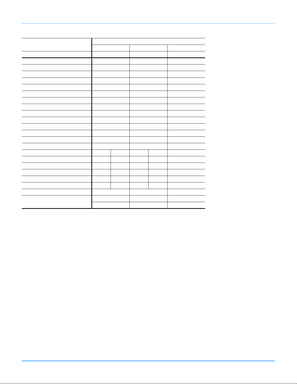
ZF090-150 Physical Data (Continued)
Component
ZF090 ZF120 ZF150
Nominal Tonnage 7.5 10 12.5
CONDENSER FAN DATA
Quantity of Fans 2 2 4
Fan diameter (Inch) 24 24 24
Type Prop Prop Prop
Drive type Direct Direct Direct
Quantity of motors 2 2 4
Motor HP each @ 50 Hz. 3/4 3/4 3/4
No. speeds 1 1 1
RPM @ 50 Hz. 940
2
Nominal total CFM 7600 9500 13900
BELT DRIVE EVAP FAN DATA
Quantity 1 1 1
Fan Size (Inch) 12 x 12 15 x 15 15 x 15
Type Centrifugal Centrifugal Centrifugal
Motor Sheave 1VM50 1VM50 1VM50 1VP56 1VP56
Blower Sheave AK59 AK54 AK74 AK66 BK72
Belt A49 A47 A54 A56 BX56
Motor HP each @ 50 Hz. 2224 4
RPM @ 50 Hz. 1425
3
1425
3
Frame size 56 56 56 184T 184T
FILTERS
Quantity - Size
4 - (24 x 16 x 2)
4 - (24 x 16 x 4)
4, 5
6
1. 1ST Stage 60% of 2nd Stage
2. 1110 RPM 60 Hz.
3. 1725 RPM 60 Hz.
4. 2 In. Throwaway, Standard, MERV (Minimum Efficiency Reporting Value) 3
5. 2 In. Pleated, Optional, MERV 7
6. 4 In. Pleated, Optional, MERV 13
Models
2
940
3
1425
1455
4 - (24 x 20 x 2)
4 - (24 x 20 x 4)
3
4,5
4 - (24 x 20 x 2)
6
4 - (24 x 20 x 4)
940
1455
2
3
4, 5
6
14 Johnson Controls Unitary Products
Page 15
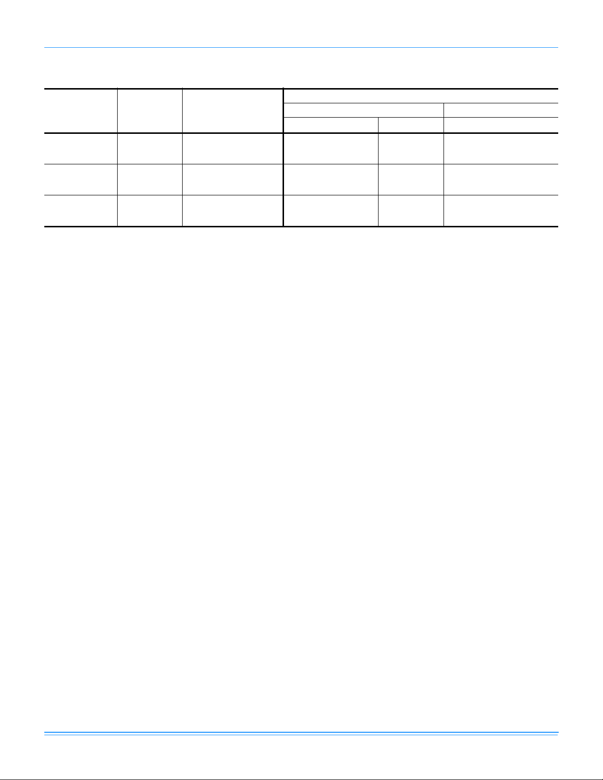
ZF078-150 Unit Limitations
Size
(Tons/KW)
Model Unit Voltage
862075-XTG-G-0415
Unit Limitations
Applied Voltage Outdoor DB Temp
Min Max Max (°F/°C)
090
(7.5/26)
120
(10/35)
150
(12.5/44)
ZF 380/415-3-50 342 457 125/52
ZF 380/415-3-50 342 457 125/52
ZF 380/415-3-50 342 457 125/52
Johnson Controls Unitary Products 15
Page 16
862075-XTG-G-0415
Capacity Performance
ZF090-150 Cooling Capacities
ZF090 (7.5 Ton) Imperial
Air on
Evaporator Coil
CFM
2250
2625
3000
3325
3650
2250
2625
3000
3325
3650
WB
(°F)
77 105.2 6.36 45.4 36.2 33.7 - - - 102.4 7.01 45.6 36.3 27.0 - - 72 98.1 6.35 58.7 49.6 45.4 31.2 - - 94.4 6.99 59.0 49.7 40.4 31.0 - 67 90.9 6.33 72.1 62.9 57.1 44.5 35.4 - 86.4 6.98 72.4 63.1 53.7 44.4 35.1 62 82.9 6.33 79.2 76.7 71.5 58.3 49.1 39.9 79.2 6.97 79.2 76.8 67.5 58.1 48.8 39.5
57 82.6 5.78 78.7 78.7 76.4 63.0 53.9 44.7 78.7 6.96 78.7 78.7 72.2 62.9 53.6 44.2
77 108.4 6.86 48.1 38.7 35.9 - - - 104.1 7.19 57.7 43.5 29.3 - - 72 101.0 6.85 63.7 53.8 48.3 34.0 - - 95.9 7.17 63.9 53.9 43.9 33.9 - 67 93.6 6.84 79.4 68.9 60.7 48.0 37.5 - 87.8 7.16 70.1 64.3 58.4 52.6 46.8 62 85.4 6.83 80.5 79.2 76.0 62.6 51.8 41.0 80.5 7.15 80.5 79.3 73.4 62.6 51.8 40.9
57 85.0 6.25 80.0 80.0 81.2 67.4 56.3 45.1 80.0 7.15 80.0 80.0 78.6 67.3 56.0 44.7
77 111.5 7.42 50.8 41.2 38.0 - - - 105.8 7.42 69.8 50.8 31.7 - - 72 103.9 7.40 68.7 58.1 51.1 36.8 - - 97.5 7.41 68.8 58.1 47.4 36.7 - 67 96.3 7.39 86.7 74.9 64.3 51.4 39.6 - 89.3 7.39 67.8 65.5 63.1 60.8 58.5 62 87.9 7.38 81.8 81.8 80.4 66.9 54.4 42.0 81.8 7.38 81.8 81.8 79.3 67.0 54.7 42.4
57 87.5 6.77 81.3 81.3 86.0 71.8 58.7 45.6 81.3 7.38 81.3 81.3 84.9 71.7 58.4 45.2
77 112.9 7.43 58.7 44.9 40.3 - - - 107.3 7.74 68.1 49.6 33.4 - - 72 105.2 7.41 74.0 62.0 54.3 38.0 - - 98.9 7.73 73.9 62.0 50.0 38.0 - 67 97.5 7.40 89.2 79.1 68.3 54.0 41.4 - 90.5 7.71 79.8 74.3 66.6 58.8 51.0 62 88.9 7.39 83.0 83.0 85.2 68.8 55.9 43.1 83.0 7.70 83.0 83.0 81.7 68.9 56.2 43.4
57 88.6 6.81 82.5 82.5 87.8 71.0 57.8 44.6 82.5 7.70 82.5 82.5 84.3 71.0 57.8 44.6
77 114.2 7.43 66.7 48.5 42.7 - - - 108.8 8.06 66.3 48.4 35.1 - - 72 106.4 7.42 79.2 65.9 57.5 39.2 - - 100.3 8.05 79.1 65.8 52.6 39.3 - 67 98.7 7.41 91.8 83.3 72.3 56.6 43.3 - 91.8 8.03 91.8 83.2 70.0 56.7 43.5 62 90.0 7.40 84.1 84.1 90.0 70.8 57.4 44.1 84.1 8.02 84.1 84.1 84.1 70.9 57.6 44.4
57 89.6 6.85 83.6 83.6 89.6 70.3 56.9 43.6 83.6 8.02 83.6 83.6 83.6 70.4 57.1 43.9
77 96.0 7.80 42.6 33.4 24.1 - - - 89.6 8.60 39.6 30.4 21.3 - - 72 88.3 7.79 55.9 46.6 37.3 28.1 - - 82.2 8.59 52.7 43.5 34.3 25.1 - 67 80.6 7.78 69.1 59.8 50.6 41.3 32.0 - 74.8 8.57 65.8 56.6 47.4 38.2 29.0 62 73.9 7.77 73.9 72.8 63.5 54.2 45.0 35.7 68.7 8.58 68.7 68.7 59.5 50.3 41.1 32.0
57 73.6 7.77 73.6 73.6 67.4 58.2 48.9 39.6 68.4 8.58 68.4 68.4 62.6 53.4 44.2 35.0
77 97.4 7.98 50.6 38.1 26.4 - - - 90.8 8.78 43.5 32.7 23.4 - - 72 89.6 7.97 60.7 50.7 40.8 30.9 - - 83.3 8.77 57.4 47.6 37.8 28.0 - 67 81.8 7.96 70.7 63.4 55.3 47.2 39.1 - 75.8 8.75 71.3 62.5 52.2 41.8 31.5 62 75.0 7.95 75.0 74.5 69.5 58.7 47.9 37.1 69.6 8.76 69.6 69.6 65.5 54.8 44.0 33.2
57 74.7 7.95 74.7 74.7 73.7 62.6 51.4 40.2 69.3 8.76 69.3 69.3 68.9 57.9 46.8 35.7
77 98.9 8.21 58.6 42.8 28.6 - - - 92.0 9.01 47.4 34.9 25.5 - - 72 90.9 8.20 65.4 54.9 44.3 33.8 - - 84.4 9.00 62.1 51.7 41.2 30.8 - 67 83.0 8.19 72.3 66.9 60.0 53.1 46.2 - 76.7 8.98 76.7 68.4 56.9 45.4 34.0 62 76.2 8.18 76.2 76.2 75.4 63.1 50.7 38.4 70.5 8.99 70.5 70.5 71.6 59.2 46.8 34.4
57 75.8 8.18 75.8 75.8 80.1 67.0 53.9 40.8 70.2 8.99 70.2 70.2 75.3 62.3 49.3 36.4
77 100.3 8.53 61.9 43.8 30.1 - - - 93.3 9.33 55.7 38.0 26.8 - - 72 92.2 8.52 70.4 58.5 46.6 34.8 - - 85.6 9.31 66.8 55.0 43.3 31.5 - 67 84.2 8.51 78.8 73.2 63.2 53.1 43.1 - 77.9 9.30 77.9 72.0 59.7 47.4 35.1 62 77.3 8.50 77.3 77.3 76.9 64.1 51.4 38.6 71.6 9.30 71.6 71.6 72.1 59.3 46.6 33.8
57 76.9 8.50 76.9 76.9 79.0 65.9 52.7 39.6 71.3 9.30 71.3 71.3 73.8 60.7 47.7 34.7
77 101.7 8.85 65.2 44.8 31.6 - - - 94.7 9.65 64.1 41.2 28.1 - - 72 93.6 8.84 75.3 62.1 48.9 35.7 - - 86.9 9.63 71.6 58.4 45.3 32.2 - 67 85.4 8.83 85.4 79.5 66.3 53.1 39.9 - 79.0 9.62 79.0 75.7 62.6 49.4 36.3 62 78.4 8.82 78.4 78.4 78.4 65.2 52.0 38.8 72.6 9.62 72.6 72.6 72.6 59.5 46.4 33.2
57 78.0 8.82 78.0 78.0 78.0 64.8 51.6 38.4 72.3 9.62 72.3 72.3 72.3 59.2 46.1 32.9
Total
Capacity
(MBh)
Total
1,2
Input
3
(kW)
Sensible Capacity (MBh)
Return Dry Bulb (°F) Return Dry Bulb (°F)
90 85 80 75 70 65 90 85 80 75 70 65
85°F 95°F
105°F 115°F
Temperature of Air on Condenser Coil
Total
1,2
Capacity
(MBh)
(kW)
Total
Input
Sensible Capacity (MBh)
3
16 Johnson Controls Unitary Products
Page 17
862075-XTG-G-0415
ZF090 (7.5 Ton) Imperial (Continued)
Air on
Evaporator Coil
CFM
2250
2625
3000
3325
3650
WB
(°F)
77 88.3 8.85 33.5 26.8 20.2 - - - 85.8 9.48 21.5 19.8 18.1 - - 72 80.4 8.84 46.7 40.1 33.4 26.8 - - 76.9 9.47 35.1 33.4 31.6 29.9 - 67 72.5 8.84 59.9 53.3 46.6 40.0 33.3 - 68.0 9.45 48.6 46.9 45.2 43.5 41.7 62 68.0 8.83 64.0 63.4 56.8 50.1 43.5 36.8 66.8 9.45 54.8 53.1 51.4 49.7 47.9 46.2
57 67.8 8.83 64.2 63.6 59.2 52.5 45.9 39.2 66.6 9.45 55.9 54.2 52.5 50.8 49.1 47.4
77 89.2 9.04 36.7 29.1 22.5 - - - 86.1 9.66 23.3 22.1 20.8 - - 72 81.5 9.03 50.8 43.8 36.8 29.8 - - 78.0 9.64 38.0 36.4 34.8 33.3 - 67 73.7 9.02 64.9 58.5 51.0 43.6 36.1 - 69.8 9.63 52.6 50.8 48.9 47.0 45.1 62 68.9 9.02 66.6 65.9 62.5 54.7 46.9 39.0 67.7 9.63 60.6 58.6 56.6 54.5 52.5 50.4
57 68.7 9.01 66.8 66.1 65.1 57.2 49.2 41.2 67.5 9.63 61.8 59.8 57.8 55.8 53.8 51.7
77 90.1 9.28 39.8 31.3 24.8 - - - 86.4 9.88 25.1 24.3 23.5 - - 72 82.5 9.26 54.9 47.5 40.1 32.8 - - 79.0 9.87 40.9 39.5 38.0 36.6 - 67 75.0 9.26 69.9 63.7 55.5 47.2 38.9 - 71.6 9.86 56.7 54.6 52.6 50.5 48.5 62 69.8 9.25 69.2 68.3 68.2 59.2 50.2 41.3 68.5 9.86 66.5 64.1 61.7 59.4 57.0 54.6
57 69.6 9.24 69.4 68.6 71.1 61.8 52.4 43.1 68.4 9.86 67.8 65.4 63.1 60.8 58.4 56.1
77 91.7 9.60 45.7 33.5 25.5 - - - 88.6 10.20 26.2 24.7 23.1 - - 72 83.7 9.59 58.9 50.5 42.1 33.7 - - 80.1 10.19 43.6 41.8 39.9 38.0 - 67 75.8 9.58 72.2 67.6 58.7 49.9 41.0 - 71.7 10.18 61.1 58.9 56.7 54.5 52.4 62 70.9 9.57 70.5 70.1 69.6 60.4 51.2 42.0 69.6 10.17 68.5 67.1 64.8 62.4 60.1 57.8
57 70.6 9.56 70.5 70.1 71.2 61.8 52.4 43.0 69.4 10.17 69.1 67.9 66.2 63.9 61.6 59.3
77 93.3 9.92 51.6 35.7 26.2 - - - 90.7 10.51 27.3 25.0 22.7 - - 72 85.0 9.91 63.0 53.6 44.1 34.7 - - 81.3 10.51 46.4 44.1 41.8 39.5 - 67 76.6 9.90 74.4 71.4 62.0 52.5 43.1 - 71.9 10.50 65.5 63.2 60.8 58.5 56.2 62 71.9 9.89 71.9 71.8 71.0 61.5 52.1 42.6 70.6 10.49 70.6 70.2 67.8 65.5 63.2 60.9
57 71.7 9.88 71.7 71.7 71.3 61.8 52.4 42.9 70.4 10.49 70.4 70.4 69.3 67.0 64.7 62.4
Total
Capacity
(MBh)
Total
1,2
Input
3
(kW)
Sensible Capacity (MBh)
Return Dry Bulb (°F) Return Dry Bulb (°F)
90 85 80 75 70 65 90 85 80 75 70 65
118.4°F 125°F
1. These capacities are gross ratings. For net capacity, deduct air blower motor, MBh = 3.415 x kW. Refer to the appropriate Blower
Performance Table for the kW of the supply air blower motor.
2. Capacity rating are based on 80 F (26.6 C) Entering Air Dry Bulb Temperature.
3. These ratings include the condenser fan motors, the compressor motors and supply air blower motor (External Static Pressure 0.25 IWG/
62.3 Pa).
Temperature of Air on Condenser Coil
Total
1,2
Capacity
(MBh)
(kW)
Total
Input
Sensible Capacity (MBh)
3
Johnson Controls Unitary Products 17
Page 18

862075-XTG-G-0415
ZF090 (26 kW) Metric
Air on
Evaporator Coil
WB
3
m
/s
(°C)
25 30.8 6.36 13.3 10.6 9.9 - - - 30.0 7.01 13.4 10.6 7.9 - - 22 28.7 6.35 17.2 14.5 13.3 9.1 - - 27.7 6.99 17.3 14.6 11.8 9.1 - -
1.06
19 26.6 6.33 21.1 18.4 16.7 13.1 10.4 - 25.3 6.98 21.2 18.5 15.8 13.0 10.3 17 24.3 6.33 23.2 22.5 20.9 17.1 14.4 11.7 23.2 6.97 23.2 22.5 19.8 17.0 14.3 11.6
14 24.2 5.78 23.1 23.1 22.4 18.5 15.8 13.1 23.1 6.96 23.1 23.1 21.2 18.4 15.7 13.0
25 31.8 6.86 14.1 11.3 10.5 - - - 30.5 7.19 16.9 12.8 8.6 - - 22 29.6 6.85 18.7 15.8 14.1 10.0 - - 28.1 7.17 18.7 15.8 12.9 9.9 - -
1.24
19 27.4 6.84 23.3 20.2 17.8 14.1 11.0 - 25.7 7.16 20.5 18.8 17.1 15.4 13.7 17 25.0 6.83 23.6 23.2 22.3 18.3 15.2 12.0 23.6 7.15 23.6 23.2 21.5 18.3 15.2 12.0
14 24.9 6.25 23.5 23.5 23.8 19.8 16.5 13.2 23.5 7.14 23.5 23.5 23.0 19.7 16.4 13.1
25 32.7 7.42 14.9 12.1 11.1 - - - 31.0 7.42 20.5 14.9 9.3 - - 22 30.5 7.40 20.1 17.0 15.0 10.8 - - 28.6 7.40 20.2 17.0 13.9 10.8 - -
1.42
19 28.2 7.39 25.4 22.0 18.8 15.1 11.6 - 26.2 7.39 19.9 19.2 18.5 17.8 17.1 17 25.8 7.38 24.0 24.0 23.6 19.6 16.0 12.3 24.0 7.38 24.0 24.0 23.2 19.6 16.0 12.4
14 25.6 6.77 23.8 23.8 25.2 21.0 17.2 13.4 23.8 7.38 23.8 23.8 24.9 21.0 17.1 13.3
25 33.1 7.43 17.2 13.1 11.8 - - - 31.4 7.74 20.0 14.5 9.8 - - 22 30.8 7.41 21.7 18.2 15.9 11.1 - - 29.0 7.73 21.7 18.2 14.6 11.1 - -
1.57
19 28.6 7.40 26.2 23.2 20.0 15.8 12.1 - 26.5 7.71 23.4 21.8 19.5 17.2 14.9 17 26.1 7.39 24.3 24.3 25.0 20.2 16.4 12.6 24.3 7.70 24.3 24.3 23.9 20.2 16.5 12.7
14 26.0 6.81 24.2 24.2 25.7 20.8 16.9 13.1 24.2 7.70 24.2 24.2 24.7 20.8 16.9 13.1
25 33.5 7.43 19.6 14.2 12.5 - - - 31.9 8.06 19.4 14.2 10.3 - - 22 31.2 7.42 23.2 19.3 16.8 11.5 - - 29.4 8.05 23.2 19.3 15.4 11.5 - -
1.72
19 28.9 7.41 26.9 24.4 21.2 16.6 12.7 - 26.9 8.03 26.9 24.4 20.5 16.6 12.7 17 26.4 7.40 24.7 24.7 26.4 20.7 16.8 12.9 24.7 8.02 24.7 24.7 24.7 20.8 16.9 13.0
14 26.3 6.85 24.5 24.5 26.3 20.6 16.7 12.8 24.5 8.02 24.5 24.5 24.5 20.6 16.7 12.9
25 28.1 7.78 12.5 9.8 7.1 - - - 26.3 8.56 11.6 8.9 6.2 - - 22 25.9 7.78 16.4 13.7 10.9 8.2 - - 24.1 8.57 15.4 12.8 10.1 7.4 - -
1.06
19 23.6 7.78 20.2 17.5 14.8 12.1 9.4 - 21.9 8.57 19.3 16.6 13.9 11.2 8.5 17 21.7 7.77 21.7 21.3 18.6 15.9 13.2 10.5 20.1 8.58 20.1 20.1 17.4 14.8 12.1 9.4
14 21.6 7.77 21.6 21.6 19.8 17.0 14.3 11.6 20.0 8.58 20.0 20.0 18.4 15.7 13.0 10.3
25 28.6 7.96 14.8 11.2 7.7 - - - 26.6 8.74 12.8 9.6 6.9 - - 22 26.3 7.96 17.8 14.9 12.0 9.1 - - 24.4 8.75 16.8 13.9 11.1 8.2 - -
1.24
19 24.0 7.96 20.7 18.6 16.2 13.8 11.5 - 22.2 8.75 20.9 18.3 15.3 12.3 9.2 17 22.0 7.95 22.0 21.8 20.4 17.2 14.0 10.9 20.4 8.76 20.4 20.4 19.2 16.0 12.9 9.7
14 21.9 7.95 21.9 21.9 21.6 18.3 15.1 11.8 20.3 8.76 20.3 20.3 20.2 17.0 13.7 10.5
25 29.0 8.19 17.2 12.6 8.4 - - - 27.0 8.97 13.9 10.2 7.5 - - 22 26.6 8.19 19.2 16.1 13.0 9.9 - - 24.7 8.98 18.2 15.1 12.1 9.0 - -
1.42
19 24.3 8.19 21.2 19.6 17.6 15.6 13.5 - 22.5 8.98 22.5 20.1 16.7 13.3 10.0 17 22.3 8.18 22.3 22.3 22.1 18.5 14.9 11.3 20.7 8.99 20.7 20.7 21.0 17.3 13.7 10.1
14 22.2 8.18 22.2 22.2 23.5 19.6 15.8 12.0 20.6 8.99 20.6 20.6 22.1 18.3 14.5 10.7
25 29.4 8.51 18.1 12.8 8.8 - - - 27.4 9.29 16.3 11.2 7.9 - - 22 27.0 8.51 20.6 17.1 13.7 10.2 - - 25.1 9.29 19.6 16.1 12.7 9.2 - -
1.57
19 24.7 8.51 23.1 21.5 18.5 15.6 12.6 - 22.8 9.30 22.8 21.1 17.5 13.9 10.3 17 22.6 8.50 22.6 22.6 22.5 18.8 15.1 11.3 21.0 9.30 21.0 21.0 21.1 17.4 13.6 9.9
14 22.5 8.50 22.5 22.5 23.2 19.3 15.5 11.6 20.9 9.30 20.9 20.9 21.6 17.8 14.0 10.2
25 29.8 8.83 19.1 13.1 9.3 - - - 27.8 9.61 18.8 12.1 8.2 - - 22 27.4 8.83 22.1 18.2 14.3 10.5 - - 25.5 9.61 21.0 17.1 13.3 9.4 - -
1.72
19 25.0 8.83 25.0 23.3 19.4 15.6 11.7 - 23.2 9.62 23.2 22.2 18.3 14.5 10.6 17 23.0 8.82 23.0 23.0 23.0 19.1 15.2 11.4 21.3 9.62 21.3 21.3 21.3 17.4 13.6 9.7
14 22.9 8.82 22.9 22.9 22.9 19.0 15.1 11.3 21.2 9.62 21.2 21.2 21.2 17.3 13.5 9.7
Total
Capacity
(kW)
Total
1,2
Input
3
(kW)
Sensible Capacity (kW)
Return Dry Bulb (°C) Return Dry Bulb (°C)
32 29 27 24 21 18 32 29 27 24 21 18
Total
Capacity
(kW)
Total
1,2
Input
3
(kW)
Sensible Capacity (kW)
29°C 35°C
41°C 46°C
Temperature of Air on Condenser Coil
18 Johnson Controls Unitary Products
Page 19

862075-XTG-G-0415
ZF090 (26 kW) Metric (Continued)
Air on
Evaporator Coil
WB
3
m
/s
(°C)
25 25.9 8.85 9.8 7.9 5.9 - - - 25.2 9.48 6.3 5.8 5.3 - - -
1.06
1.24
1.42
1.57
1.72
22 23.6 8.84 13.7 11.7 9.8 7.8 - - 22.5 9.47 10.3 9.8 9.3 8.8 - 19 21.2 8.84 17.6 15.6 13.7 11.7 9.8 - 19.9 9.45 14.2 13.7 13.2 12.7 12.2 17 19.9 8.83 18.7 18.6 16.6 14.7 12.7 10.8 19.6 9.45 16.1 15.6 15.1 14.6 14.0 13.5
14 19.9 8.83 18.8 18.6 17.3 15.4 13.4 11.5 19.5 9.45 16.4 15.9 15.4 14.9 14.4 13.9
25 26.1 9.04 10.7 8.5 6.6 - - - 25.2 9.66 6.8 6.5 6.1 - - 22 23.9 9.03 14.9 12.8 10.8 8.7 - - 22.8 9.64 11.1 10.7 10.2 9.7 - 19 21.6 9.02 19.0 17.1 15.0 12.8 10.6 - 20.5 9.63 15.4 14.9 14.3 13.8 13.2 17 20.2 9.02 19.5 19.3 18.3 16.0 13.7 11.4 19.8 9.63 17.8 17.2 16.6 16.0 15.4 14.8
14 20.1 9.01 19.6 19.4 19.1 16.8 14.4 12.1 19.8 9.63 18.1 17.5 16.9 16.3 15.8 15.2
25 26.4 9.28 11.7 9.2 7.3 - - - 25.3 9.88 7.4 7.1 6.9 - - 22 24.2 9.26 16.1 13.9 11.8 9.6 - - 23.1 9.87 12.0 11.6 11.1 10.7 - 19 22.0 9.26 20.5 18.7 16.3 13.8 11.4 - 21.0 9.86 16.6 16.0 15.4 14.8 14.2 17 20.5 9.25 20.3 20.0 20.0 17.4 14.7 12.1 20.1 9.86 19.5 18.8 18.1 17.4 16.7 16.0
14 20.4 9.24 20.3 20.1 20.8 18.1 15.4 12.6 20.0 9.86 19.9 19.2 18.5 17.8 17.1 16.4
25 26.9 9.60 13.4 9.8 7.5 - - - 26.0 10.20 7.7 7.2 6.8 - - 22 24.5 9.59 17.3 14.8 12.3 9.9 - - 23.5 10.19 12.8 12.2 11.7 11.1 - 19 22.2 9.58 21.2 19.8 17.2 14.6 12.0 - 21.0 10.18 17.9 17.3 16.6 16.0 15.3 17 20.8 9.57 20.7 20.5 20.4 17.7 15.0 12.3 20.4 10.17 20.1 19.7 19.0 18.3 17.6 16.9
14 20.7 9.56 20.7 20.6 20.9 18.1 15.4 12.6 20.3 10.17 20.2 19.9 19.4 18.7 18.0 17.4
25 27.4 9.92 15.1 10.5 7.7 - - - 26.6 10.51 8.0 7.3 6.7 - - 22 24.9 9.91 18.5 15.7 12.9 10.2 - - 23.8 10.51 13.6 12.9 12.2 11.6 - 19 22.5 9.90 21.8 20.9 18.2 15.4 12.6 - 21.1 10.50 19.2 18.5 17.8 17.2 16.5 17 21.1 9.89 21.1 21.0 20.8 18.0 15.3 12.5 20.7 10.49 20.7 20.6 19.9 19.2 18.5 17.8
14 21.0 9.88 21.0 21.0 20.9 18.1 15.4 12.6 20.6 10.49 20.6 20.6 20.3 19.6 19.0 18.3
Total
Capacity
(kW)
Total
1,2
Input
3
(kW)
Sensible Capacity (kW)
Return Dry Bulb (°C) Return Dry Bulb (°C)
32 29 27 24 21 18 32 29 27 24 21 18
48°C 52°C
1. These capacities are gross ratings. For net capacity, deduct air blower motor, MBh = 3.415 x kW. Refer to the appropriate Blower
Performance Table for the kW of the supply air blower motor.
2. Capacity rating are based on 80 F (26.6 C) Entering Air Dry Bulb Temperature.
3. These ratings include the condenser fan motors, the compressor motors and supply air blower motor (External Static Pressure 0.25 IWG/
62.3 Pa).
Temperature of Air on Condenser Coil
Total
Capacity
(kW)
Total
1,2
Input
(kW)
Sensible Capacity (kW)
3
Johnson Controls Unitary Products 19
Page 20

862075-XTG-G-0415
ZF120 (10 Ton) Imperial
Air on
Evaporator Coil
CFM
3000
3500
4000
4550
5100
3000
3500
4000
4550
5100
WB
(°F)
77 120.6 8.40 68.1 55.8 43.5 - - - 120.7 9.61 67.5 55.2 42.9 - - 72 115.1 8.47 83.7 71.4 59.1 46.8 - - 112.0 9.59 81.3 69.0 56.7 44.4 - 67 109.6 8.54 99.2 86.9 74.7 62.4 50.1 - 103.2 9.57 95.1 82.8 70.5 58.2 45.9 62 103.7 8.56 103.7 89.8 77.5 65.2 52.9 40.7 96.8 9.56 96.8 87.4 75.1 62.8 50.5 38.2
57 95.5 8.56 95.5 95.5 92.3 80.0 67.7 55.5 90.4 9.54 90.4 90.4 86.3 74.0 61.7 49.4
77 128.2 8.64 70.2 59.1 46.9 - - - 128.2 9.88 70.6 58.5 46.4 - - 72 122.4 8.71 90.3 77.0 63.7 50.4 - - 118.9 9.86 87.7 74.6 61.4 48.2 - 67 116.6 8.78 110.4 94.9 80.5 66.2 51.8 - 109.6 9.83 104.9 90.6 76.3 62.0 47.7 62 110.3 8.80 110.3 99.7 83.6 69.2 54.9 40.6 102.8 9.82 102.8 95.7 81.3 67.0 52.6 38.3
57 101.6 8.80 101.6 101.6 99.6 84.7 69.9 55.1 96.0 9.80 96.0 96.0 93.5 78.7 63.9 49.2
77 135.9 8.97 72.2 62.4 50.3 - - - 135.7 10.24 73.7 61.8 50.0 - - 72 129.7 9.04 96.9 82.6 68.3 54.1 - - 125.8 10.22 94.2 80.1 66.1 52.0 - 67 123.5 9.11 121.5 102.8 86.4 69.9 53.5 - 116.0 10.20 114.7 98.4 82.1 65.9 49.6 62 116.8 9.14 116.8 109.6 89.6 73.2 56.9 40.5 108.8 10.18 108.8 103.9 87.5 71.1 54.7 38.4
57 107.6 9.14 107.6 107.6 106.8 89.5 72.1 54.7 101.6 10.17 101.6 101.6 100.6 83.4 66.2 48.9
77 134.8 9.53 92.3 68.8 54.6 - - - 135.5 10.80 94.5 70.2 54.8 - - 72 128.7 9.60 107.0 90.6 74.2 57.8 - - 125.7 10.78 104.8 88.6 72.4 56.2 - 67 122.7 9.67 121.7 112.3 93.8 76.3 58.8 - 115.8 10.76 115.2 107.0 90.0 72.7 55.4 62 116.1 9.69 116.1 112.4 99.3 81.9 64.4 47.0 108.6 10.74 108.6 106.2 95.9 78.5 61.1 43.8
57 106.9 9.69 106.9 106.9 106.5 88.5 70.6 52.6 101.4 10.73 101.4 101.4 101.0 83.1 65.3 47.5
77 133.8 9.98 112.4 75.3 58.8 - - - 135.3 11.26 115.3 78.5 59.6 - - 72 127.8 10.05 117.1 98.6 80.0 61.5 - - 125.5 11.24 115.5 97.1 78.7 60.3 - 67 121.8 10.12 121.8 121.8 101.2 82.7 64.1 - 115.7 11.22 115.7 115.7 97.9 79.5 61.1 62 115.3 10.15 115.3 115.3 109.1 90.5 72.0 53.4 108.5 11.20 108.5 108.5 104.3 85.9 67.5 49.2
57 106.2 10.14 106.2 106.2 106.2 87.6 69.1 50.5 101.3 11.19 101.3 101.3 101.3 82.9 64.5 46.1
77 120.9 10.83 66.9 54.6 42.2 - - - 121.0 12.04 66.3 53.9 41.6 - - 72 108.8 10.72 78.9 66.6 54.3 41.9 - - 105.7 11.84 76.6 64.2 51.8 39.5 - 67 96.8 10.60 91.0 78.6 66.3 54.0 41.6 - 90.4 11.64 86.8 74.5 62.1 49.8 37.4 62 89.8 10.55 89.8 85.0 72.7 60.3 48.0 35.7 82.9 11.54 82.9 82.6 70.2 57.9 45.5 33.2
57 85.2 10.52 85.2 85.2 80.4 68.0 55.7 43.4 80.0 11.50 80.0 80.0 74.4 62.0 49.7 37.3
77 128.2 11.12 71.0 57.9 46.0 - - - 128.1 12.36 71.5 57.3 45.5 - - 72 115.4 11.01 85.2 72.1 59.0 45.9 - - 111.9 12.16 82.7 69.7 56.7 43.7 - 67 102.6 10.89 99.4 86.3 72.1 57.9 43.7 - 95.7 11.95 93.9 82.1 67.9 53.8 39.6 62 95.3 10.84 95.3 91.6 79.1 64.7 50.3 35.9 87.8 11.85 87.8 87.6 76.8 62.4 48.0 33.6
57 90.3 10.81 90.3 90.3 87.4 72.7 58.0 43.2 84.7 11.81 84.7 84.7 81.3 66.6 52.0 37.3
77 135.5 11.51 75.2 61.3 49.7 - - - 135.3 12.78 76.7 60.7 49.4 - - 72 122.0 11.40 91.5 77.7 63.8 49.9 - - 118.1 12.57 88.8 75.2 61.5 47.9 - 67 108.5 11.28 107.8 94.0 77.9 61.8 45.7 - 101.0 12.37 101.0 89.7 73.7 57.8 41.8 62 100.7 11.22 100.7 98.3 85.5 69.0 52.6 36.2 92.7 12.27 92.7 92.7 83.4 66.9 50.5 34.1
57 95.5 11.20 95.5 95.5 94.5 77.3 60.2 43.1 89.4 12.23 89.4 89.4 88.3 71.3 54.3 37.3
77 136.2 12.08 96.7 71.6 55.0 - - - 136.8 13.35 98.9 72.9 55.2 - - 72 122.6 11.96 102.7 86.7 70.6 54.6 - - 119.5 13.15 100.6 84.7 68.8 53.0 - 67 109.0 11.85 108.7 101.8 86.2 69.1 51.9 - 102.2 12.94 102.2 96.5 82.5 65.5 48.5 62 101.2 11.79 101.2 100.0 92.5 75.2 57.9 40.6 93.7 12.84 93.7 93.7 89.1 71.8 54.6 37.4
57 95.9 11.76 95.9 95.9 95.4 77.7 60.1 42.4 90.5 12.80 90.5 90.5 89.9 72.4 54.8 37.3
77 136.8 12.54 118.3 81.8 60.3 - - - 138.4 13.82 121.2 85.1 61.1 - - 72 123.2 12.43 113.9 95.7 77.4 59.2 - - 120.9 13.62 112.3 94.2 76.2 58.1 - 67 109.5 12.32 109.5 109.5 94.6 76.3 58.1 - 103.3 13.41 103.3 103.3 91.2 73.2 55.1 62 101.6 12.26 101.6 101.6 99.5 81.3 63.1 44.9 94.8 13.31 94.8 94.8 94.8 76.7 58.7 40.6
57 96.4 12.23 96.4 96.4 96.4 78.2 59.9 41.7 91.5 13.27 91.5 91.5 91.5 73.4 55.4 37.3
Total
Capacity
(MBh)
1,2
Total
Input
(kW)
Sensible Capacity (MBh)
3
90 85 80 75 70 65 90 85 80 75 70 65
Return Dry Bulb (°F) Return Dry Bulb (°F)
85°F 95°F
105°F 115°F
Temperature of Air on Condenser Coil
Total
1,2
Capacity
(MBh)
(kW)
Total
Input
Sensible Capacity (MBh)
3
20 Johnson Controls Unitary Products
Page 21

862075-XTG-G-0415
ZF120 (10 Ton) Imperial (Continued)
Air on
Evaporator Coil
CFM
3000
3500
4000
4550
5100
WB
(°F)
77 118.0 12.34 67.4 53.5 41.1 - - - 112.2 12.91 69.7 52.6 40.2 - - 72 102.1 12.21 75.7 63.3 50.9 38.6 - - 95.2 12.94 73.9 61.5 49.1 36.7 - 67 86.2 12.09 83.9 73.1 60.7 48.4 36.0 - 78.1 12.96 78.1 70.4 58.1 45.7 33.3 62 80.0 11.98 80.0 79.8 69.0 56.6 44.3 31.9 74.5 12.84 74.5 74.5 66.6 54.2 41.8 29.4
57 77.7 11.96 77.7 77.7 71.8 59.5 47.1 34.7 73.2 12.84 73.2 73.2 66.9 54.5 42.1 29.7
77 124.8 12.67 73.2 57.3 45.4 - - - 118.3 13.28 76.7 57.4 45.3 - - 72 108.1 12.53 81.8 68.7 55.7 42.6 - - 100.8 13.26 80.0 66.8 53.7 40.6 - 67 91.4 12.39 90.3 80.1 66.0 51.8 37.7 - 83.2 13.23 83.2 76.3 62.2 48.0 33.9 62 84.7 12.30 84.7 84.6 75.4 60.9 46.4 31.9 78.8 13.16 78.8 78.8 72.8 58.0 43.3 28.5
57 82.3 12.27 82.3 82.3 78.5 63.8 49.1 34.4 77.5 13.16 77.5 77.5 73.1 58.3 43.5 28.7
77 131.6 13.11 79.0 61.2 49.7 - - - 124.5 13.76 83.7 62.2 50.4 - - 72 114.1 12.95 87.9 74.2 60.4 46.7 - - 106.4 13.68 86.0 72.2 58.3 44.5 - 67 96.7 12.79 96.7 87.1 71.2 55.3 39.4 - 88.3 13.61 88.3 82.1 66.3 50.4 34.6 62 89.5 12.71 89.5 89.5 81.9 65.2 48.6 31.9 83.2 13.58 83.2 83.2 79.0 61.9 44.8 27.6
57 86.9 12.69 86.9 86.9 85.2 68.2 51.1 34.1 81.8 13.58 81.8 81.8 79.4 62.2 45.0 27.8
77 132.7 13.69 100.8 74.0 55.0 - - - 124.8 14.34 104.4 76.2 54.5 - - 72 115.5 13.52 99.5 83.7 67.6 51.6 - - 107.6 14.26 97.4 81.8 65.3 48.8 - 67 98.2 13.36 98.2 93.4 80.3 63.1 45.9 - 90.4 14.17 90.4 87.3 76.0 58.5 41.0 62 90.5 13.29 90.5 90.5 86.7 69.2 51.6 34.1 84.2 14.16 84.2 84.2 82.1 63.9 45.8 27.6
57 87.8 13.26 87.8 87.8 87.0 69.3 51.5 33.8 82.8 14.15 82.8 82.8 81.5 63.4 45.2 27.0
77 133.9 14.16 122.6 86.8 60.2 - - - 125.2 14.82 125.2 90.2 58.6 - - 72 116.8 14.00 111.1 93.2 74.8 56.4 - - 108.8 14.73 108.8 91.4 72.2 53.0 - 67 99.6 13.83 99.6 99.6 89.4 70.9 52.5 - 92.5 14.64 92.5 92.5 85.7 66.6 47.4 62 91.5 13.76 91.5 91.5 91.5 73.1 54.6 36.2 85.1 14.64 85.1 85.1 85.1 66.0 46.8 27.6
57 88.8 13.74 88.8 88.8 88.8 70.4 52.0 33.5 83.7 14.63 83.7 83.7 83.7 64.5 45.4 26.2
Total
Capacity
(MBh)
Total
1,2
Input
3
(kW)
Sensible Capacity (MBh)
Return Dry Bulb (°F) Return Dry Bulb (°F)
90 85 80 75 70 65 90 85 80 75 70 65
118.4°F 125°F
1. These capacities are gross ratings. For net capacity, deduct air blower motor, MBh = 3.415 x kW. Refer to the appropriate Blower
Performance Table for the kW of the supply air blower motor.
2. Capacity rating are based on 80 F (26.6 C) Entering Air Dry Bulb Temperature.
3. These ratings include the condenser fan motors, the compressor motors and supply air blower motor (External Static Pressure 0.30 IWG/
74.7 Pa).
Temperature of Air on Condenser Coil
Total
1,2
Capacity
(MBh)
(kW)
Total
Input
Sensible Capacity (MBh)
3
Johnson Controls Unitary Products 21
Page 22

862075-XTG-G-0415
ZF120 (35 kW) Metric
Air on
Evaporator Coil
WB
3
m
/s
(°C)
25 35.3 8.40 20.0 16.4 12.8 - - - 35.4 9.61 19.8 16.2 12.6 - - 22 33.7 8.47 24.5 20.9 17.3 13.7 - - 32.8 9.59 23.8 20.2 16.6 13.0 - -
1.42
19 32.1 8.54 29.1 25.5 21.9 18.3 14.7 - 30.2 9.57 27.9 24.3 20.7 17.0 13.4 17 30.4 8.56 30.4 26.3 22.7 19.1 15.5 11.9 28.4 9.56 28.4 25.6 22.0 18.4 14.8 11.2
14 28.0 8.56 28.0 28.0 27.1 23.5 19.9 16.3 26.5 9.54 26.5 26.5 25.3 21.7 18.1 14.5
25 37.6 8.64 20.6 17.3 13.8 - - - 37.6 9.88 20.7 17.2 13.6 - - 22 35.9 8.71 26.5 22.6 18.7 14.8 - - 34.8 9.86 25.7 21.9 18.0 14.1 - -
1.65
19 34.2 8.78 32.3 27.8 23.6 19.4 15.2 - 32.1 9.83 30.7 26.6 22.4 18.2 14.0 17 32.3 8.80 32.3 29.2 24.5 20.3 16.1 11.9 30.1 9.82 30.1 28.0 23.8 19.6 15.4 11.2
14 29.8 8.80 29.8 29.8 29.2 24.8 20.5 16.2 28.1 9.80 28.1 28.1 27.4 23.1 18.7 14.4
25 39.8 8.97 21.2 18.3 14.7 - - - 39.8 10.24 21.6 18.1 14.7 - - 22 38.0 9.04 28.4 24.2 20.0 15.8 - - 36.9 10.22 27.6 23.5 19.4 15.2 - -
1.89
19 36.2 9.11 35.6 30.1 25.3 20.5 15.7 - 34.0 10.20 33.6 28.8 24.1 19.3 14.5 17 34.2 9.14 34.2 32.1 26.3 21.5 16.7 11.9 31.9 10.18 31.9 30.5 25.7 20.8 16.0 11.2
14 31.5 9.14 31.5 31.5 31.3 26.2 21.1 16.0 29.8 10.17 29.8 29.8 29.5 24.4 19.4 14.3
25 39.5 9.53 27.0 20.2 16.0 - - - 39.7 10.80 27.7 20.6 16.1 - - 22 37.7 9.60 31.4 26.5 21.7 16.9 - - 36.8 10.78 30.7 26.0 21.2 16.5 - -
2.15
19 36.0 9.67 35.7 32.9 27.5 22.4 17.2 - 33.9 10.76 33.8 31.4 26.4 21.3 16.2 17 34.0 9.69 34.0 33.0 29.1 24.0 18.9 13.8 31.8 10.74 31.8 31.1 28.1 23.0 17.9 12.8
14 31.3 9.69 31.3 31.3 31.2 26.0 20.7 15.4 29.7 10.73 29.7 29.7 29.6 24.4 19.1 13.9
25 39.2 9.98 32.9 22.1 17.2 - - - 39.7 11.26 33.8 23.0 17.5 - - 22 37.5 10.05 34.3 28.9 23.5 18.0 - - 36.8 11.24 33.8 28.5 23.1 17.7 - -
2.41
19 35.7 10.12 35.7 35.7 29.7 24.2 18.8 - 33.9 11.22 33.9 33.9 28.7 23.3 17.9 17 33.8 10.15 33.8 33.8 32.0 26.5 21.1 15.7 31.8 11.20 31.8 31.8 30.6 25.2 19.8 14.4
14 31.1 10.14 31.1 31.1 31.1 25.7 20.2 14.8 29.7 11.19 29.7 29.7 29.7 24.3 18.9 13.5
25 35.4 10.83 19.6 16.0 12.4 - - - 35.5 12.04 19.4 15.8 12.2 - - 22 31.9 10.72 23.1 19.5 15.9 12.3 - - 31.0 11.84 22.4 18.8 15.2 11.6 - -
1.42
19 28.4 10.60 26.7 23.0 19.4 15.8 12.2 - 26.5 11.64 25.4 21.8 18.2 14.6 11.0 17 26.3 10.55 26.3 24.9 21.3 17.7 14.1 10.5 24.3 11.54 24.3 24.2 20.6 17.0 13.3 9.7
14 25.0 10.52 25.0 25.0 23.6 19.9 16.3 12.7 23.4 11.50 23.4 23.4 21.8 18.2 14.6 10.9
25 37.6 11.12 20.8 17.0 13.5 - - - 37.6 12.36 21.0 16.8 13.3 - - 22 33.8 11.01 25.0 21.1 17.3 13.5 - - 32.8 12.16 24.2 20.4 16.6 12.8 - -
1.65
19 30.1 10.89 29.1 25.3 21.1 17.0 12.8 - 28.0 11.95 27.5 24.1 19.9 15.8 11.6 17 27.9 10.84 27.9 26.9 23.2 19.0 14.7 10.5 25.7 11.85 25.7 25.7 22.5 18.3 14.1 9.9
14 26.5 10.81 26.5 26.5 25.6 21.3 17.0 12.7 24.8 11.81 24.8 24.8 23.8 19.5 15.2 10.9
25 39.7 11.51 22.0 18.0 14.6 - - - 39.6 12.78 22.5 17.8 14.5 - - 22 35.8 11.40 26.8 22.8 18.7 14.6 - - 34.6 12.57 26.0 22.0 18.0 14.0 - -
1.89
19 31.8 11.28 31.6 27.6 22.8 18.1 13.4 - 29.6 12.37 29.6 26.3 21.6 16.9 12.3 17 29.5 11.22 29.5 28.8 25.0 20.2 15.4 10.6 27.2 12.27 27.2 27.2 24.4 19.6 14.8 10.0
14 28.0 11.20 28.0 28.0 27.7 22.7 17.6 12.6 26.2 12.23 26.2 26.2 25.9 20.9 15.9 10.9
25 39.9 12.08 28.3 21.0 16.1 - - - 40.1 13.35 29.0 21.4 16.2 - - 22 35.9 11.96 30.1 25.4 20.7 16.0 - - 35.0 13.15 29.5 24.8 20.2 15.5 - -
2.15
19 31.9 11.85 31.9 29.8 25.3 20.2 15.2 - 29.9 12.94 29.9 28.3 24.2 19.2 14.2 17 29.7 11.79 29.7 29.3 27.1 22.0 17.0 11.9 27.5 12.84 27.5 27.5 26.1 21.1 16.0 11.0
14 28.1 11.76 28.1 28.1 28.0 22.8 17.6 12.4 26.5 12.80 26.5 26.5 26.3 21.2 16.1 10.9
25 40.1 12.54 34.7 24.0 17.7 - - - 40.6 13.82 35.5 24.9 17.9 - - 22 36.1 12.43 33.4 28.0 22.7 17.4 - - 35.4 13.62 32.9 27.6 22.3 17.0 - -
2.41
19 32.1 12.32 32.1 32.1 27.7 22.4 17.0 - 30.3 13.41 30.3 30.3 26.7 21.4 16.2 17 29.8 12.26 29.8 29.8 29.2 23.8 18.5 13.2 27.8 13.31 27.8 27.8 27.8 22.5 17.2 11.9
14 28.2 12.23 28.2 28.2 28.2 22.9 17.6 12.2 26.8 13.27 26.8 26.8 26.8 21.5 16.2 10.9
Total
Capacity
(kW)
Total
1,2
Input
3
(kW)
Sensible Capacity (kW)
Return Dry Bulb (°C) Return Dry Bulb (°C)
32 29 27 24 21 18 32 29 27 24 21 18
Total
Capacity
(kW)
Total
1
Input
2
(kW)
Sensible Capacity (kW)
29°C 35°C
41°C 46°C
Temperature of Air on Condenser Coil
22 Johnson Controls Unitary Products
Page 23

862075-XTG-G-0415
ZF120 (35 kW) Metric (Continued)
Air on
Evaporator Coil
WB
3
m
/s
(°C)
25 34.6 12.34 19.8 15.7 12.1 - - - 32.9 12.91 20.4 15.4 11.8 - - -
1.42
1.65
1.89
2.15
2.41
22 29.9 12.21 22.2 18.5 14.9 11.3 - - 27.9 12.94 21.7 18.0 14.4 10.8 - 19 25.3 12.09 24.6 21.4 17.8 14.2 10.5 - 22.9 12.96 22.9 20.6 17.0 13.4 9.8 17 23.5 11.98 23.5 23.4 20.2 16.6 13.0 9.3 21.8 12.84 21.8 21.8 19.5 15.9 12.3 8.6
14 22.8 11.96 22.8 22.8 21.0 17.4 13.8 10.2 21.5 12.84 21.5 21.5 19.6 16.0 12.3 8.7
25 36.6 12.67 21.5 16.8 13.3 - - - 34.7 13.28 22.5 16.8 13.3 - - 22 31.7 12.53 24.0 20.1 16.3 12.5 - - 29.5 13.26 23.4 19.6 15.7 11.9 - 19 26.8 12.39 26.5 23.5 19.3 15.2 11.0 - 24.4 13.23 24.4 22.4 18.2 14.1 9.9 17 24.8 12.30 24.8 24.8 22.1 17.9 13.6 9.3 23.1 13.16 23.1 23.1 21.3 17.0 12.7 8.4
14 24.1 12.27 24.1 24.1 23.0 18.7 14.4 10.1 22.7 13.16 22.7 22.7 21.4 17.1 12.8 8.4
25 38.6 13.11 23.2 17.9 14.6 - - - 36.5 13.76 24.5 18.2 14.8 - - 22 33.5 12.95 25.8 21.7 17.7 13.7 - - 31.2 13.68 25.2 21.1 17.1 13.0 - 19 28.3 12.79 28.3 25.5 20.9 16.2 11.5 - 25.9 13.61 25.9 24.1 19.4 14.8 10.1 17 26.2 12.71 26.2 26.2 24.0 19.1 14.2 9.4 24.4 13.58 24.4 24.4 23.2 18.1 13.1 8.1
14 25.5 12.69 25.5 25.5 25.0 20.0 15.0 10.0 24.0 13.58 24.0 24.0 23.3 18.2 13.2 8.1
25 38.9 13.69 29.5 21.7 16.1 - - - 36.6 14.34 30.6 22.3 16.0 - - 22 33.8 13.52 29.2 24.5 19.8 15.1 - - 31.5 14.26 28.5 24.0 19.1 14.3 - 19 28.8 13.36 28.8 27.4 23.5 18.5 13.5 - 26.5 14.17 26.5 25.6 22.3 17.1 12.0 17 26.5 13.29 26.5 26.5 25.4 20.3 15.1 10.0 24.7 14.16 24.7 24.7 24.1 18.7 13.4 8.1
14 25.7 13.26 25.7 25.7 25.5 20.3 15.1 9.9 24.3 14.15 24.3 24.3 23.9 18.6 13.2 7.9
25 39.2 14.16 35.9 25.5 17.7 - - - 36.7 14.82 36.7 26.4 17.2 - - 22 34.2 14.00 32.6 27.3 21.9 16.5 - - 31.9 14.73 31.9 26.8 21.2 15.5 - 19 29.2 13.83 29.2 29.2 26.2 20.8 15.4 - 27.1 14.64 27.1 27.1 25.1 19.5 13.9 17 26.8 13.76 26.8 26.8 26.8 21.4 16.0 10.6 25.0 14.64 25.0 25.0 25.0 19.3 13.7 8.1
14 26.0 13.74 26.0 26.0 26.0 20.6 15.2 9.8 24.5 14.63 24.5 24.5 24.5 18.9 13.3 7.7
Total
Capacity
(kW)
Total
1,2
Input
3
(kW)
Sensible Capacity (kW)
Return Dry Bulb (°C) Return Dry Bulb (°C)
32 29 27 24 21 18 32 29 27 24 21 18
48°C 52°C
1. These capacities are gross ratings. For net capacity, deduct air blower motor, MBh = 3.415 x kW. Refer to the appropriate Blower
Performance Table for the kW of the supply air blower motor.
2. Capacity rating are based on 80 F (26.6 C) Entering Air Dry Bulb Temperature.
3. These ratings include the condenser fan motors, the compressor motors and supply air blower motor (External Static Pressure 0.30 IWG/
74.7 Pa).
Temperature of Air on Condenser Coil
Total
Capacity
(kW)
Total
1
Input
(kW)
Sensible Capacity (kW)
2
Johnson Controls Unitary Products 23
Page 24

862075-XTG-G-0415
ZF150 (12.5 Ton) Imperial
Air on
Evaporator Coil
CFM
WB
(°F)
77 185.6 11.34 82.4 66.9 51.4 - - - 170.6 12.56 79.4 64.1 48.9 - - 72 168.8 11.18 104.3 88.8 73.3 57.8 - - 155.7 12.43 100.6 85.3 70.1 54.8 - -
3750
67 151.9 11.02 126.3 110.8 95.2 79.7 64.2 - 140.7 12.29 121.8 106.5 91.3 76.0 60.7 62 146.1 10.96 145.6 122.7 106.4 90.9 75.4 59.8 134.2 12.23 133.9 118.6 103.4 88.1 72.9 57.6
57 141.4 10.92 141.4 133.8 116.3 100.8 85.3 69.8 131.0 12.20 131.0 125.9 110.6 95.4 80.1 64.9
77 190.5 11.63 85.8 71.6 55.5 - - - 175.4 12.85 83.8 68.3 52.7 - - 72 173.2 11.47 112.8 96.0 79.2 62.4 - - 160.0 12.71 108.4 92.0 75.6 59.2 - -
4375
67 155.9 11.31 139.8 120.4 102.9 85.4 67.8 - 144.7 12.57 133.0 115.8 98.5 81.2 63.9 62 149.9 11.25 149.7 136.9 115.0 96.9 78.9 60.9 138.0 12.51 137.8 129.3 111.5 93.8 76.0 58.3
57 145.1 11.21 145.1 141.3 125.7 107.3 88.9 70.4 134.6 12.48 134.6 132.1 119.4 101.3 83.2 65.0
77 195.4 11.89 89.2 76.3 59.6 - - - 180.2 13.12 88.3 72.4 56.6 - - 72 177.6 11.73 121.3 103.2 85.1 67.0 - - 164.4 12.98 116.3 98.7 81.1 63.5 - -
5000
67 159.9 11.57 153.4 130.1 110.6 91.0 71.5 - 148.6 12.84 144.3 125.0 105.7 86.4 67.1 62 153.8 11.51 153.8 151.0 123.5 103.0 82.5 61.9 141.7 12.78 141.7 139.9 119.7 99.5 79.2 59.0
57 148.8 11.47 148.8 148.8 135.1 113.8 92.4 71.1 138.3 12.75 138.3 138.3 128.1 107.1 86.2 65.2
77 200.8 12.68 93.4 80.3 60.9 - - - 184.3 13.90 95.8 77.0 58.2 - - 72 182.6 12.52 127.2 107.0 86.9 66.7 - - 168.2 13.76 122.8 103.2 83.5 63.8 - -
5575
67 164.3 12.36 161.0 133.8 112.9 92.0 71.1 - 152.0 13.62 149.8 129.3 108.7 88.2 67.7 62 158.0 12.30 158.0 156.7 126.7 105.3 83.9 62.5 145.0 13.55 145.0 144.1 123.2 102.2 81.2 60.2
57 152.9 12.26 152.9 152.9 139.2 117.4 95.6 73.8 141.5 13.53 141.5 141.5 131.8 110.5 89.1 67.7
77 206.2 13.46 97.6 84.3 62.1 - - - 188.5 14.67 103.4 81.6 59.9 - - 72 187.5 13.30 133.1 110.9 88.6 66.4 - - 172.0 14.53 129.4 107.6 85.8 64.1 - -
6150
67 168.8 13.14 168.6 137.4 115.1 92.9 70.6 - 155.5 14.39 155.3 133.6 111.8 90.0 68.3 62 162.3 13.08 162.3 162.3 129.8 107.5 85.3 63.1 148.3 14.32 148.3 148.3 126.6 104.9 83.1 61.3
57 157.0 13.04 157.0 157.0 143.3 121.1 98.8 76.6 144.7 14.30 144.7 144.7 135.6 113.8 92.0 70.3
77 155.6 13.79 76.4 61.4 46.4 - - - 140.6 15.02 73.4 58.6 43.9 - - 72 142.6 13.67 96.8 81.8 66.8 51.8 - - 129.5 14.92 93.1 78.4 63.6 48.9 - -
3750
67 129.5 13.56 117.3 102.3 87.3 72.3 57.3 - 118.3 14.83 112.8 98.1 83.3 68.6 53.8 62 122.3 13.49 122.2 114.6 100.4 85.4 70.4 55.4 110.5 14.76 110.5 110.5 97.4 82.6 67.9 53.1
57 120.6 13.48 120.6 118.0 104.9 89.9 74.9 59.9 110.2 14.76 110.2 110.2 99.2 84.5 69.8 55.0
77 160.3 14.08 81.9 65.0 50.0 - - - 145.2 15.30 79.9 61.7 47.2 - - 72 146.9 13.96 104.0 88.0 72.0 56.0 - - 133.7 15.20 99.6 84.0 68.4 52.8 - -
4375
67 133.4 13.84 126.2 111.1 94.0 77.0 60.0 - 122.2 15.11 119.4 106.4 89.6 72.8 56.1 62 126.0 13.78 125.9 121.7 108.1 90.6 73.2 55.7 114.1 15.04 114.1 114.1 104.7 87.5 70.3 53.2
57 124.2 13.76 124.2 122.9 113.0 95.2 77.4 59.6 113.8 15.04 113.8 113.8 106.7 89.2 71.7 54.2
77 165.0 14.34 87.3 68.6 53.5 - - - 149.8 15.56 86.4 64.7 50.5 - - 72 151.1 14.22 111.2 94.2 77.1 60.1 - - 137.9 15.47 106.2 89.7 73.2 56.7 - -
5000
67 137.3 14.10 135.1 119.8 100.8 81.7 62.7 - 126.0 15.37 126.0 114.7 95.9 77.1 58.3 62 129.7 14.04 129.7 128.8 115.8 95.9 76.0 56.1 117.7 15.30 117.7 117.7 112.0 92.4 72.8 53.2
57 127.8 14.03 127.8 127.8 121.1 100.5 79.9 59.3 117.3 15.30 117.3 117.3 114.2 93.9 73.7 53.5
77 167.9 15.11 98.2 73.7 55.6 - - - 151.5 16.32 100.6 70.5 52.9 - - 72 153.8 14.99 118.4 99.3 80.1 60.9 - - 139.5 16.23 114.1 95.4 76.7 58.1 - -
5575
67 139.8 14.87 138.6 124.8 104.6 84.5 64.3 - 127.5 16.13 127.5 120.3 100.5 80.7 60.9 62 132.0 14.81 132.0 131.6 119.7 99.1 78.5 57.9 119.0 16.06 119.0 119.0 116.2 96.0 75.8 55.6
57 130.1 14.80 130.1 130.1 124.5 103.5 82.6 61.6 118.7 16.06 118.7 118.7 117.1 96.6 76.0 55.5
77 170.9 15.87 109.2 78.9 57.6 - - - 153.2 17.07 114.9 76.2 55.4 - - 72 156.5 15.75 125.6 104.4 83.1 61.8 - - 141.1 16.98 121.9 101.1 80.3 59.5 - -
6150
67 142.2 15.63 142.1 129.8 108.5 87.2 65.9 - 128.9 16.88 128.9 126.0 105.2 84.4 63.6 62 134.3 15.57 134.3 134.3 123.5 102.2 80.9 59.6 120.4 16.81 120.4 120.4 120.4 99.5 78.7 57.9
57 132.4 15.56 132.4 132.4 127.8 106.5 85.2 63.9 120.0 16.82 120.0 120.0 120.0 99.2 78.4 57.6
Total
Capacity
(MBh)
1,2
Total
Input
(kW)
Temperature of Air on Condenser Coil
Sensible Capacity (MBh)
3
90 85 80 75 70 65 90 85 80 75 70 65
Return Dry Bulb (°F) Return Dry Bulb (°F)
Total
Capacity
(MBh)
Total
1,2
Input
3
(kW)
Sensible Capacity (MBh)
85°F 95°F
105°F 115°F
24 Johnson Controls Unitary Products
Page 25

862075-XTG-G-0415
ZF150 (12.5 Ton) Imperial (Continued)
Air on
Evaporator Coil
CFM
3750
4375
5000
5575
6150
WB
(°F)
77 136.5 15.57 71.2 56.3 41.4 - - - 128.4 16.65 67.0 51.9 36.7 - - 72 125.7 15.43 91.0 76.1 61.3 46.4 - - 118.5 16.41 87.0 71.9 56.7 41.5 - 67 115.0 15.28 110.9 96.0 81.1 66.2 51.3 - 108.5 16.17 107.1 91.9 76.7 61.5 46.4 62 104.8 15.16 104.8 104.8 96.2 81.3 66.4 51.5 93.9 15.95 93.9 93.9 93.9 78.7 63.5 48.3
57 104.5 15.16 104.5 104.5 97.3 82.4 67.5 52.6 93.6 15.95 93.6 93.6 93.6 78.4 63.2 48.1
77 140.9 15.85 78.2 59.1 44.5 - - - 132.6 16.91 75.0 54.3 39.4 - - 72 129.8 15.71 97.4 81.6 65.9 50.1 - - 122.3 16.70 93.1 77.1 61.0 44.9 - 67 118.7 15.58 116.7 104.2 87.2 70.2 53.2 - 112.0 16.48 111.3 99.9 82.5 65.1 47.8 62 108.2 15.45 108.2 108.2 104.1 86.7 69.2 51.8 96.9 16.23 96.9 96.9 103.1 85.1 67.0 49.0
57 107.9 15.45 107.9 107.9 105.8 88.1 70.5 52.8 96.6 16.23 96.6 96.6 104.1 86.1 68.1 50.0
77 145.4 16.10 85.2 62.0 47.7 - - - 136.9 17.15 83.0 56.6 42.2 - - 72 133.9 15.97 103.8 87.2 70.5 53.8 - - 126.2 16.96 99.2 82.2 65.2 48.2 - 67 122.4 15.85 122.4 112.3 93.3 74.2 55.2 - 115.5 16.77 115.5 107.8 88.3 68.7 49.2 62 111.7 15.71 111.7 111.7 112.1 92.1 72.0 52.0 100.0 16.50 100.0 100.0 112.3 91.4 70.5 49.7
57 111.3 15.71 111.3 111.3 114.3 93.9 73.4 53.0 99.7 16.49 99.7 99.7 114.6 93.7 72.9 52.0
77 146.6 16.85 99.5 68.2 50.4 - - - 137.2 17.88 97.2 63.7 45.4 - - 72 135.5 16.74 111.9 92.9 73.9 54.9 - - 127.6 17.72 107.6 88.0 68.4 48.8 - 67 124.3 16.62 124.3 117.6 97.4 77.3 57.1 - 118.1 17.57 118.1 112.3 91.4 70.5 49.6 62 112.9 16.47 112.9 112.9 113.2 92.5 71.8 51.2 101.1 17.26 101.1 101.1 107.3 85.7 64.2 42.6
57 112.6 16.47 112.6 112.6 114.1 93.2 72.4 51.5 100.8 17.26 100.8 100.8 108.3 86.7 65.2 43.6
77 147.9 17.59 113.7 74.4 53.1 - - - 137.5 18.60 111.4 70.8 48.6 - - 72 137.0 17.49 119.9 98.6 77.3 56.0 - - 129.1 18.48 116.0 93.8 71.6 49.3 - 67 126.1 17.38 126.1 122.9 101.6 80.3 59.0 - 120.7 18.35 120.7 116.8 94.6 72.3 50.1 62 114.2 17.22 114.2 114.2 114.2 92.9 71.6 50.3 102.3 18.01 102.3 102.3 102.3 80.0 57.8 35.6
57 113.9 17.22 113.9 113.9 113.9 92.6 71.3 50.0 102.0 18.01 102.0 102.0 102.0 79.7 57.5 35.2
Total
Capacity
(MBh)
Total
1,2
Input
3
(kW)
Sensible Capacity (MBh)
Return Dry Bulb (°F) Return Dry Bulb (°F)
90 85 80 75 70 65 90 85 80 75 70 65
118.4°F 125°F
1. These capacities are gross ratings. For net capacity, deduct air blower motor, MBh = 3.415 x kW. Refer to the appropriate Blower
Performance Table for the kW of the supply air blower motor.
2. Capacity rating are based on 80 F (26.6 C) Entering Air Dry Bulb Temperature.
3. These ratings include the condenser fan motors, the compressor motors and supply air blower motor (External Static Pressure 0.35 IWG/
87.1 Pa).
Temperature of Air on Condenser Coil
Total
1,2
Capacity
(MBh)
(kW)
Total
Input
Sensible Capacity (MBh)
3
Johnson Controls Unitary Products 25
Page 26

862075-XTG-G-0415
ZF150 (44 kW) Metric
Air on
Evaporator Coil
WB
3
m
/s
(°C)
25 54.4 11.34 24.1 19.6 15.1 - - - 50.0 12.56 23.3 18.8 14.3 - - 22 49.5 11.18 30.6 26.0 21.5 16.9 - - 45.6 12.43 29.5 25.0 20.5 16.1 - -
1.77
19 44.5 11.02 37.0 32.5 27.9 23.4 18.8 - 41.2 12.29 35.7 31.2 26.7 22.3 17.8 17 42.8 10.96 42.7 36.0 31.2 26.6 22.1 17.5 39.3 12.23 39.2 34.8 30.3 25.8 21.4 16.9
14 41.4 10.92 41.4 39.2 34.1 29.6 25.0 20.5 38.4 12.20 38.4 36.9 32.4 28.0 23.5 19.0
25 55.8 11.63 25.2 21.0 16.3 - - - 51.4 12.85 24.6 20.0 15.5 - - 22 50.8 11.47 33.1 28.1 23.2 18.3 - - 46.9 12.71 31.8 27.0 22.2 17.3 - -
2.06
19 45.7 11.31 41.0 35.3 30.2 25.0 19.9 - 42.4 12.57 39.0 33.9 28.9 23.8 18.7 17 43.9 11.25 43.9 40.1 33.7 28.4 23.1 17.8 40.4 12.51 40.4 37.9 32.7 27.5 22.3 17.1
14 42.5 11.21 42.5 41.4 36.8 31.4 26.0 20.6 39.5 12.48 39.5 38.7 35.0 29.7 24.4 19.1
25 57.3 11.89 26.2 22.4 17.5 - - - 52.8 13.12 25.9 21.2 16.6 - - 22 52.1 11.73 35.6 30.2 24.9 19.6 - - 48.2 12.98 34.1 28.9 23.8 18.6 - -
2.36
19 46.9 11.57 45.0 38.1 32.4 26.7 20.9 - 43.6 12.84 42.3 36.6 31.0 25.3 19.7 17 45.1 11.51 45.1 44.3 36.2 30.2 24.2 18.1 41.5 12.78 41.5 41.0 35.1 29.2 23.2 17.3
14 43.6 11.47 43.6 43.6 39.6 33.3 27.1 20.8 40.5 12.75 40.5 40.5 37.5 31.4 25.3 19.1
25 58.8 12.68 27.4 23.5 17.8 - - - 54.0 13.90 28.1 22.6 17.1 - - 22 53.5 12.52 37.3 31.4 25.5 19.5 - - 49.3 13.76 36.0 30.2 24.5 18.7 - -
2.63
19 48.2 12.36 47.2 39.2 33.1 27.0 20.8 - 44.6 13.62 43.9 37.9 31.9 25.9 19.8 17 46.3 12.30 46.3 45.9 37.1 30.9 24.6 18.3 42.5 13.55 42.5 42.2 36.1 29.9 23.8 17.6
14 44.8 12.26 44.8 44.8 40.8 34.4 28.0 21.6 41.5 13.53 41.5 41.5 38.6 32.4 26.1 19.9
25 60.4 13.46 28.6 24.7 18.2 - - - 55.2 14.67 30.3 23.9 17.5 - - 22 54.9 13.30 39.0 32.5 26.0 19.5 - - 50.4 14.53 37.9 31.5 25.2 18.8 - -
2.90
19 49.5 13.14 49.4 40.3 33.7 27.2 20.7 - 45.6 14.39 45.5 39.2 32.8 26.4 20.0 17 47.6 13.08 47.6 47.6 38.0 31.5 25.0 18.5 43.5 14.32 43.5 43.5 37.1 30.7 24.4 18.0
14 46.0 13.04 46.0 46.0 42.0 35.5 29.0 22.4 42.4 14.30 42.4 42.4 39.7 33.3 27.0 20.6
25 45.6 11.34 22.4 18.0 13.6 - - - 41.2 15.02 21.5 17.2 12.9 - - 22 41.8 11.18 28.4 24.0 19.6 15.2 - - 37.9 14.92 27.3 23.0 18.6 14.3 - -
1.77
19 38.0 11.02 34.4 30.0 25.6 21.2 16.8 - 34.7 14.83 33.1 28.7 24.4 20.1 15.8 17 35.9 10.96 35.8 33.6 29.4 25.0 20.6 16.2 32.4 14.76 32.4 32.4 28.5 24.2 19.9 15.6
14 35.3 10.92 35.3 34.6 30.8 26.4 22.0 17.6 32.3 14.76 32.3 32.3 29.1 24.8 20.4 16.1
25 47.0 11.63 24.0 19.0 14.6 - - - 42.6 15.30 23.4 18.1 13.8 - - 22 43.0 11.47 30.5 25.8 21.1 16.4 - - 39.2 15.20 29.2 24.6 20.0 15.5 - -
2.06
19 39.1 11.31 37.0 32.5 27.6 22.6 17.6 - 35.8 15.11 35.0 31.2 26.3 21.3 16.4 17 36.9 11.25 36.9 35.7 31.7 26.6 21.5 16.3 33.4 15.04 33.4 33.4 30.7 25.6 20.6 15.6
14 36.4 11.21 36.4 36.0 33.1 27.9 22.7 17.5 33.3 15.04 33.3 33.3 31.3 26.1 21.0 15.9
25 48.4 11.89 25.6 20.1 15.7 - - - 43.9 15.56 25.3 19.0 14.8 - - 22 44.3 11.73 32.6 27.6 22.6 17.6 - - 40.4 15.47 31.1 26.3 21.4 16.6 - -
2.36
19 40.2 11.57 39.6 35.1 29.5 24.0 18.4 - 36.9 15.37 36.9 33.6 28.1 22.6 17.1 17 38.0 11.51 38.0 37.7 34.0 28.1 22.3 16.4 34.5 15.30 34.5 34.5 32.8 27.1 21.3 15.6
14 37.5 11.47 37.5 37.5 35.5 29.5 23.4 17.4 34.4 15.30 34.4 34.4 33.5 27.5 21.6 15.7
25 49.2 12.68 28.8 21.6 16.3 - - - 44.4 16.32 29.5 20.6 15.5 - - 22 45.1 12.52 34.7 29.1 23.5 17.9 - - 40.9 16.23 33.4 28.0 22.5 17.0 - -
2.63
19 41.0 12.36 40.6 36.6 30.7 24.8 18.8 - 37.4 16.13 37.4 35.3 29.5 23.7 17.9 17 38.7 12.30 38.7 38.6 35.1 29.0 23.0 17.0 34.9 16.06 34.9 34.9 34.0 28.1 22.2 16.3
14 38.1 12.26 38.1 38.1 36.5 30.3 24.2 18.1 34.8 16.06 34.8 34.8 34.3 28.3 22.3 16.3
25 50.1 13.46 32.0 23.1 16.9 - - - 44.9 17.07 33.7 22.3 16.2 - - 22 45.9 13.30 36.8 30.6 24.3 18.1 - - 41.3 16.98 35.7 29.6 23.5 17.4 - -
2.90
19 41.7 13.14 41.7 38.0 31.8 25.6 19.3 - 37.8 16.88 37.8 36.9 30.8 24.7 18.6 17 39.4 13.08 39.4 39.4 36.2 30.0 23.7 17.5 35.3 16.81 35.3 35.3 35.3 29.2 23.1 17.0
14 38.8 13.04 38.8 38.8 37.5 31.2 25.0 18.7 35.2 16.82 35.2 35.2 35.2 29.1 23.0 16.9
Total
Capacity
(kW)
Total
1,2
Input
3
(kW)
Sensible Capacity (kW)
Return Dry Bulb (°C) Return Dry Bulb (°C)
32 29 27 24 21 18 32 29 27 24 21 18
Total
Capacity
(kW)
Total
1,2
Input
3
(kW)
Sensible Capacity (kW)
29°C 35°C
41°C 46°C
Temperature of Air on Condenser Coil
26 Johnson Controls Unitary Products
Page 27

862075-XTG-G-0415
ZF150 (44 kW) Metric (Continued)
Air on
Evaporator Coil
WB
3
m
/s
(°C)
25 40.0 15.57 20.9 16.5 12.1 - - - 37.6 16.65 19.6 15.2 10.8 - - -
1.77
2.06
2.36
2.63
2.90
22 36.8 15.43 26.7 22.3 18.0 13.6 - - 34.7 16.41 25.5 21.1 16.6 12.2 - 19 33.7 15.28 32.5 28.1 23.8 19.4 15.0 - 31.8 16.17 31.4 26.9 22.5 18.0 13.6 17 30.7 15.16 30.7 30.7 28.2 23.8 19.5 15.1 27.5 15.95 27.5 27.5 27.5 23.1 18.6 14.2
14 30.6 15.16 30.6 30.6 28.5 24.2 19.8 15.4 27.4 15.95 27.4 27.4 27.4 23.0 18.5 14.1
25 41.3 15.85 22.9 17.3 13.1 - - - 38.9 16.91 22.0 15.9 11.6 - - 22 38.0 15.71 28.6 23.9 19.3 14.7 - - 35.9 16.70 27.3 22.6 17.9 13.2 - 19 34.8 15.58 34.2 30.5 25.6 20.6 15.6 - 32.8 16.48 32.6 29.3 24.2 19.1 14.0 17 31.7 15.45 31.7 31.7 30.5 25.4 20.3 15.2 28.4 16.23 28.4 28.4 30.2 24.9 19.6 14.4
14 31.6 15.45 31.6 31.6 31.0 25.8 20.7 15.5 28.3 16.23 28.3 28.3 30.5 25.2 19.9 14.7
25 42.6 16.10 25.0 18.2 14.0 - - - 40.1 17.15 24.3 16.6 12.4 - - 22 39.2 15.97 30.4 25.5 20.7 15.8 - - 37.0 16.96 29.1 24.1 19.1 14.1 - 19 35.9 15.85 35.9 32.9 27.3 21.8 16.2 - 33.9 16.77 33.9 31.6 25.9 20.1 14.4 17 32.7 15.71 32.7 32.7 32.9 27.0 21.1 15.2 29.3 16.50 29.3 29.3 32.9 26.8 20.7 14.6
14 32.6 15.71 32.6 32.6 33.5 27.5 21.5 15.5 29.2 16.49 29.2 29.2 33.6 27.5 21.4 15.2
25 43.0 16.85 29.2 20.0 14.8 - - - 40.2 17.88 28.5 18.7 13.3 - - 22 39.7 16.74 32.8 27.2 21.7 16.1 - - 37.4 17.72 31.5 25.8 20.0 14.3 - 19 36.4 16.62 36.4 34.5 28.6 22.6 16.7 - 34.6 17.57 34.6 32.9 26.8 20.7 14.5 17 33.1 16.47 33.1 33.1 33.2 27.1 21.1 15.0 29.6 17.26 29.6 29.6 31.4 25.1 18.8 12.5
14 33.0 16.47 33.0 33.0 33.4 27.3 21.2 15.1 29.5 17.26 29.5 29.5 31.7 25.4 19.1 12.8
25 43.3 17.59 33.3 21.8 15.6 - - - 40.3 18.60 32.6 20.7 14.2 - - 22 40.1 17.49 35.1 28.9 22.7 16.4 - - 37.8 18.48 34.0 27.5 21.0 14.5 - 19 37.0 17.38 37.0 36.0 29.8 23.5 17.3 - 35.4 18.35 35.4 34.2 27.7 21.2 14.7 17 33.5 17.22 33.5 33.5 33.5 27.2 21.0 14.7 30.0 18.01 30.0 30.0 30.0 23.5 16.9 10.4
14 33.4 17.22 33.4 33.4 33.4 27.1 20.9 14.7 29.9 18.01 29.9 29.9 29.9 23.4 16.8 10.3
Total
Capacity
(kW)
Total
1,2
Input
3
(kW)
Sensible Capacity (kW)
Return Dry Bulb (°C) Return Dry Bulb (°C)
32 29 27 24 21 18 32 29 27 24 21 18
48°C 52°C
1. These capacities are gross ratings. For net capacity, deduct air blower motor, MBh = 3.415 x kW. Refer to the appropriate Blower
Performance Table for the kW of the supply air blower motor.
2. Capacity rating are based on 80 F (26.6 C) Entering Air Dry Bulb Temperature.
3. These ratings include the condenser fan motors, the compressor motors and supply air blower motor (External Static Pressure 0.35 IWG/
87.1 Pa).
Temperature of Air on Condenser Coil
Total
Capacity
(kW)
Total
1,2
Input
(kW)
Sensible Capacity (kW)
3
Johnson Controls Unitary Products 27
Page 28

862075-XTG-G-0415
Airflow Performance
ZF090-150 Side Duct Application
ZF090 (7.5 Ton) Standard Motor Side Duct Imperial
ESP
(iwg)
CFM Watts BHP CFM Watts BHP CFM Watts BHP CFM Watts BHP CFM Watts BHP CFM Watts BHP
0.2
3690 2230 2.39 3468 1950 2.09 3294 1750 1.88 3105 1550 1.66 2922 1370 1.47 2694 1210 1.30
0.4
3478 2110 2.26 3239 1830 1.96 3044 1640 1.76 2850 1440 1.54 2651 1270 1.36 2423 1120 1.20
0.6
3243 1980 2.12 3001 1720 1.85 2790 1520 1.63 2576 1330 1.43 2370 1170 1.26 2105 1020 1.09
0.8
3006 1830 1.96 2758 1580 1.70 2544 1400 1.50 2303 1230 1.32 2017 1050 1.13 1624 880 0.94
1.0
2758 1720 1.85 2533 1510 1.62 2230 1290 1.38 1891 1080 1.16 – – – – – –
1.2
2447 1570 1.68 2182 1350 1.45 1769 1110 1.19 – – – – – – – – –
1.4
2085 1410 1.51 – – – – – – – – – – – – – – –
1.6
ZF090 (26 kW) Standard Motor Side Duct Metric
012345
– – – – – – – – – – – – 3193 1490 1.60 2981 1310 1.41
Turns Open
ESP
(Pa)
m3/s
50
1.74 2.23 1.78 1.64 1.95 1.55 1.55 1.75 1.40 1.46 1.55 1.24 1.38 1.37 1.10 1.27 1.21 0.97
100
1.64 2.11 1.68 1.53 1.83 1.46 1.44 1.64 1.39 1.34 1.44 1.15 1.25 1.27 1.01 1.14 1.12 0.89
149
1.53 1.98 1.58 1.42 1.72 1.38 1.32 1.52 1.38 1.22 1.33 1.07 1.12 1.17 0.94 0.99 1.02 0.81
199
1.42 1.83 1.46 1.30 1.58 1.27 1.20 1.40 1.28 1.09 1.23 0.98 0.95 1.05 0.84 0.77 0.88 0.70
249
1.30 1.72 1.38 1.20 1.51 1.21 1.05 1.29 1.17 0.89 1.08 0.91 – – – – – –
299
1.15 1.57 1.25 1.03 1.35 1.08 0.83 1.1 1 1.01 – – – – – – – – –
349
0.98 1.41 1.26 – – – – – – – – – – – – – – –
399
012345
In Out
– – – – – – – – – – – – 1.51 1.49 1.19 1.36 1.31 1.05
m3/s
In Out
m3/s
ZF090 (7.5) Ton Optional Motor Side Duct Imperial
ESP
(iwg)
CFM Watts BHP CFM Watts BHP CFM Watts BHP CFM Watts BHP CFM Watts BHP CFM Watts BHP
0.25
0.5
0.8
3555 2440 2.62 3285 2120 2.27 3047 1860 2.00 2778 1590 1.71 2507 1390 1.49 2209 1180 1.27
1
3320 2310 2.48 3034 1990 2.13 2799 1730 1.86 2510 1480 1.59 2213 1260 1.35 1846 1050 1.13
1.2
3101 2160 2.32 2796 1860 2.00 2466 1590 1.71 2188 1330 1.43 1721 1090 1.17 – – –
1.4
2864 2040 2.19 2489 1710 1.83 2145 1450 1.56 – – – – – – – – –
1.6
2524 1860 2.00 2182 1550 1.66 – – – – – – – – – – – –
1.8
012345
– – – – – – – – – – – – 3650 1800 1.95 3290 1560 1.68
– – – – – – – – – – – – 3250 1650 1.78 2930 1430 1.53
– – – – – – – – – – – – 2783 1500 1.61 2507 1300 1.39
Turns Open
In Out
Turns Open
m3/s
In Out
m3/s
In Out
m3/s
In Out
28 Johnson Controls Unitary Products
Page 29

ZF090 (7.5) Ton Optional Motor Side Duct Imperial
ESP
(iwg)
CFM Watts BHP CFM Watts BHP CFM Watts BHP CFM Watts BHP CFM Watts BHP CFM Watts BHP
2189 1680 1.80 – – – – – – – – – – – – – – –
2
012345
862075-XTG-G-0415
Turns Open
Johnson Controls Unitary Products 29
Page 30

862075-XTG-G-0415
ZF090 (26 kW) Optional Motor Side Duct Metric
ESP
(Pa)
m3/s
62
125
199
1.68 2.44 1.95 1.55 2.12 1.70 1.44 1.86 1.49 1.31 1.59 1.27 1.18 1.39 1.11 1.04 1.18 0.94
249
1.52 2.31 1.85 1.43 1.99 1.59 1.32 1.73 1.38 1.18 1.48 1.18 1.04 1.26 1.01 0.87 1.05 0.84
299
1.46 2.16 1.73 1.31 1.86 1.49 1.16 1.59 1.27 1.03 1.33 1.06 0.81 1.09 0.87 – – –
349
1.35 2.04 1.63 1.17 1.71 1.36 1.01 1.45 1.16 – – – – – – – – –
399
1.19 1.86 1.49 1.03 1.55 1.24 – – – – – – – – – – – –
448
1.03 1.68 1.34 – – – – – – – – – – – – – – –
498
0 1 2 3 4 5
In
Out
(kW)
m3/s
(kW)
– – – – – – – – – – – – 1.72 1.8 1.46 1.55 1.56 1.25
– – – – – – – – – – – – 1.53 1.65 1.33 1.38 1.43 1.14
– – – – – – – – – – – – 1.31 1.5 1.20 1.18 1.3 1.04
In
(kW)
Out
(kW)
m3/s
ZF120 (10 Ton) Standard Motor Side Duct Imperial
In
(kW)
Turns Open
Out
m3/s
(kW)
In
(kW)
Out
(kW)
m3/s
In
(kW)
Out
(kW)
m3/s
In
(kW)
Out
(kW)
ESP
(iwg)
CFM Watts BHP CFM Watts BHP CFM Watts BHP CFM Watts BHP CFM Watts BHP CFM Watts BHP
0.35
4820 2675 2.87 4582 2362 2.53 4319 2080 2.23 4086 1842 1.98 3863 1648 1.77 3590 1430 1.53
0.6
4522 2496 2.68 4307 2215 2.38 4025 1941 2.08 3713 1678 1.80 3464 1499 1.61 3149 1291 1.38
0.8
4223 2332 2.50 3973 2062 2.21 3656 1783 1.91 3363 1550 1.66 3026 1350 1.45 - - -
1.0
3913 2174 2.33 3679 1923 2.06 3262 1619 1.74 2721 1330 1.43 - - - - - -
1.2
3521 1978 2.12 3104 1693 1.82 - - - - - - - - - - - -
1.4
2790 1660 1.78 - - - - - - - - - - - - - - -
0 1 2 3 4 5
ZF120 (35 kW) Standard Motor Side Duct Metric
ESP
(Pa)
m3/s
87
2.27 2.68 2.14 2.16 2.36 1.89 2.04 2.08 1.66 1.93 1.84 1.47 1.82 1.65 1.32 1.69 1.43 1.14
149
2.13 2.50 2.00 2.03 2.22 1.77 1.90 1.94 1.55 1.75 1.68 1.34 1.63 1.50 1.20 1.49 1.29 1.03
199
1.99 2.33 1.87 1.88 2.06 1.65 1.73 1.78 1.43 1.59 1.55 1.24 1.43 1.35 1.08 - - -
249
1.85 2.17 1.74 1.74 1.92 1.54 1.54 1.62 1.30 1.28 1.33 1.06 - - - - - -
299
1.66 1.98 1.58 1.46 1.69 1.35 - - - - - - - - - - - -
349
1.32 1.66 1.33 - - - - - - - - - - - - - - -
0 1 2 3 4 5
In
(kW)
Out
(kW)
m3/s
In
(kW)
Out
(kW)
m3/s
In
(kW)
Turns Open
Turns Open
Out
m3/s
(kW)
In
(kW)
Out
(kW)
m3/s
In
(kW)
Out
(kW)
m3/s
In
(kW)
Out
(kW)
30 Johnson Controls Unitary Products
Page 31

ZF120 (10 Ton) Optional Motor Side Duct Imperial
ESP
(iwg)
CFM Watts BHP CFM Watts BHP CFM Watts BHP CFM Watts BHP CFM Watts BHP CFM Watts BHP
0.35
0.6
0.8
1.0
1.2
1.4
5079 3595 3.86 4787 3105 3.33 4452 2713 2.91 4012 2259 2.42 3665 1926 2.07 - - -
1.6
4739 3316 3.56 4482 2892 3.10 4098 2474 2.65 3543 2006 2.15 3057 1642 1.76 - - -
1.8
4461 3111 3.34 4070 2621 2.81 3552 2160 2.32 - - - - - - - - -
2.0
3997 2782 2.98 3400 2219 2.38 - - - - - - - - - - - -
2.2
3496 2480 2.66 - - - - - - - - - - - - - - -
0 1 2 3 4 5
- - - - - - - - - - - - - - - 5100 2495 2.68
- - - - - - - - - - - - 5091 2745 2.94 4646 2314 2.48
- - - - - - - - - 5078 2937 3.15 4839 2584 2.77 4347 2153 2.31
- - - - - - 5075 3117 3.34 4767 2730 2.93 4487 2377 2.55 3946 1942 2.08
- - - 5068 3308 3.55 4742 2881 3.09 4427 2513 2.69 4108 2159 2.32 3501 1723 1.85
862075-XTG-G-0415
Turns Open
ZF120 (35 kW) Optional Motor Side Duct Metric
ESP
(Pa)
m3/s
87
149
199
249
299
349
2.40 3.60 2.88 2.26 3.11 2.48 2.10 2.71 2.17 1.89 2.26 1.81 1.73 1.93 1.54 - - -
399
2.24 3.32 2.65 2.12 2.89 2.31 1.93 2.47 1.98 1.67 2.01 1.60 1.44 1.64 1.31 - - -
448
2.11 3.11 2.49 1.92 2.62 2.10 1.68 2.16 1.73 - - - - - - - - -
498
1.89 2.78 2.23 1.60 2.22 1.78 - - - - - - - - - - - -
548
1.65 2.48 1.98 - - - - - - - - - - - - - - -
0 1 2 3 4 5
In
Out
(kW)
m3/s
(kW)
- - - - - - - - - - - - - - - 2.4 2.50 2.00
- - - - - - - - - - - - 2.40 2.75 2.20 2.19 2.31 1.85
- - - - - - - - - 2.40 2.94 2.35 2.28 2.58 2.07 2.05 2.15 1.72
- - - - - - 2.40 3.12 2.49 2.25 2.73 2.18 2.12 2.38 1.90 1.86 1.94 1.55
- - - 2.39 3.31 2.65 2.24 2.88 2.30 2.09 2.51 2.01 1.94 2.16 1.73 1.65 1.72 1.38
In
(kW)
Out
(kW)
m3/s
In
(kW)
Turns Open
Out
m3/s
(kW)
In
(kW)
Out
(kW)
m3/s
In
(kW)
Out
(kW)
m3/s
In
(kW)
Out
(kW)
Johnson Controls Unitary Products 31
Page 32

862075-XTG-G-0415
ZF150 (12.5 Ton) Side Duct Imperial
ESP
(iwg)
CFM Watts BHP CFM Watts BHP CFM Watts BHP CFM Watts BHP CFM Watts BHP CFM Watts BHP
0.35
0.6
0.8
5870 4273 4.58 5567 3715 3.98 5406 3380 3.62 5078 2937 3.15 4839 2584 2.77 4347 2153 2.31
1.0
5652 4087 4.38 5327 3518 3.77 5075 3117 3.34 4767 2730 2.93 4487 2377 2.55 3946 1942 2.08
1.2
5350 3820 4.10 5068 3308 3.55 4742 2881 3.09 4427 2513 2.69 4108 2159 2.32 - - -
1.4
5079 3595 3.86 4787 3105 3.33 4452 2713 2.91 4012 2259 2.42 3665 1926 2.07 - - -
1.6
4739 3316 3.56 4482 2892 3.10 4098 2474 2.65 - - - - - - - - -
1.8
4461 3111 3.34 4070 2621 2.81 - - - - - - - - - - - -
2.0
3997 2782 2.98 - - - - - - - - - - - - - - -
0 1 2 3 4 5
- - - 6150 4171 4.47 5915 3774 4.05 5610 3309 3.55 5396 2948 3.16 4960 2495 2.68
- - - 5850 3932 4.22 5648 3565 3.82 5363 3136 3.36 5091 2745 2.94 4646 2314 2.48
ZF150 (44 kW) Side Duct Metric
Turns Open
Turns Open
ESP
(Pa)
m3/s
87
149
199
2.77 4.27 3.42 2.63 3.72 2.97 2.55 3.38 2.70 2.40 2.94 2.35 2.28 2.58 2.07 2.05 2.15 1.72
249
2.67 4.09 3.27 2.51 3.52 2.81 2.40 3.12 2.49 2.25 2.73 2.18 2.12 2.38 1.90 1.86 1.94 1.55
299
2.52 3.82 3.06 2.39 3.31 2.65 2.24 2.88 2.30 2.09 2.51 2.01 1.94 2.16 1.73 - - -
349
2.40 3.60 2.88 2.26 3.11 2.48 2.10 2.71 2.17 1.89 2.26 1.81 1.73 1.93 1.54 - - -
399
2.24 3.32 2.65 2.12 2.89 2.31 1.93 2.47 1.98 - - - - - - - - -
448
2.11 3.11 2.49 1.92 2.62 2.10 - - - - - - - - - - -
498
1.89 2.78 2.23 - - - - - - - - - - - - - - -
0 1 2 3 4 5
In
Out
(kW)
m3/s
(kW)
- - - 2.90 4.17 3.34 2.79 3.77 3.02 2.65 3.31 2.65 2.55 2.95 2.36 2.34 2.50 2.00
- - - 2.76 3.93 3.15 2.67 3.57 2.85 2.53 3.14 2.51 2.40 2.75 2.20 2.19 2.31 1.85
In
(kW)
Out
(kW)
m3/s
In
(kW)
Out
(kW)
m3/s
In
(kW)
Out
(kW)
m3/s
In
(kW)
Out
(kW)
m3/s
In
(kW)
Out
(kW)
32 Johnson Controls Unitary Products
Page 33

ZF090-150 Bottom Duct Application
ZF090 (7.5 Ton) Standard Motor Bottom Duct Imperial
ESP
(iwg)
CFM Watts BHP CFM Watts BHP CFM Watts BHP CFM Watts BHP CFM Watts BHP CFM Watts BHP
3478 2110 2.26 3239 1830 1.96 3044 1640 1.76 2850 1440 1.54 2651 1270 1.36 2423 1120 1.20
0.2
3243 1980 2.12 3001 1720 1.85 2790 1520 1.63 2576 1330 1.43 2370 1170 1.26 2105 1020 1.09
0.4
3006 1830 1.96 2758 1580 1.70 2544 1400 1.50 2303 1230 1.32 2017 1050 1.13 1624 880 0.94
0.6
2758 1720 1.85 2533 1510 1.62 2230 1290 1.38 1891 1080 1.16 – – – – – –
0.8
2447 1570 1.68 2182 1350 1.45 1769 1110 1.19 – – – – – – – – –
1.0
2085 1410 1.51 – – – – – – – – – – – – – – –
1.2
ZF090 (26 kW) Standard Motor Bottom Duct Metric
ESP
(Pa)
m3/s
1.64 2.11 1.68 1.53 1.83 1.46 1.44 1.64 1.39 1.34 1.44 1.15 1.25 1.27 1.01 1.14 1.12 0.89
50
1.53 1.98 1.58 1.42 1.72 1.38 1.32 1.52 1.38 1.22 1.33 1.07 1.12 1.17 0.94 0.99 1.02 0.81
100
1.42 1.83 1.46 1.30 1.58 1.27 1.20 1.40 1.28 1.09 1.23 0.98 0.95 1.05 0.84 0.77 0.88 0.70
149
1.30 1.72 1.38 1.20 1.51 1.21 1.05 1.29 1.17 0.89 1.08 0.91 – – – – – –
199
1.15 1.57 1.25 1.03 1.35 1.08 0.83 1.11 1.01 – – – – – – – – –
249
0.98 1.41 1.26 – – – – – – – – – – – – – – –
299
012345
0 1 2 3 4 5
In
(kW)
Out
(kW)
m3/s
In
(kW)
Out
(kW)
m3/s
(kW)
In
Turns Open
Turns Open
Out
m3/s
(kW)
In
(kW)
Out
(kW)
m3/s
In
(kW)
Out
(kW)
862075-XTG-G-0415
In
(kW)
Out
(kW)
m3/s
ZF090 (7.5 Ton) Optional Motor Bottom Duct Imperial
Turns Open
ESP
(iwg)
CFM Watts BHP CFM Watts BHP CFM Watts BHP CFM Watts BHP CFM Watts BHP CFM Watts BHP
0.4
0.6
0.8
3101 2160 2.32 2796 1860 2.00 2466 1590 1.71 2188 1330 1.43 1721 1090 1.17 – – –
1.0
2864 2040 2.19 2489 1710 1.83 2145 1450 1.56 – – – – – – – – –
1.2
2524 1860 2.00 2182 1550 1.66 – – – – – – – – – – – –
1.4
2189 1680 1.80 – – – – – – – – – – – – – – –
1.6
0 1 2 3 4 5
– – – – – – – – – – – – 2783 1500 1.61 2507 1300 1.39
– – – 3285 2120 2.27 3047 1860 2.00 2778 1590 1.71 2507 1390 1.49 2209 1180 1.27
– – – 3034 1990 2.13 2799 1730 1.86 2510 1480 1.59 2213 1260 1.35 1846 1050 1.13
Johnson Controls Unitary Products 33
Page 34

862075-XTG-G-0415
ZF090 (26 kW) Optional Motor Bottom Duct Metric
Turns Open
ESP
(Pa)
m3/s
100
1.67 2.44 1.95 1.55 2.12 1.70 1.44 1.86 1.49 1.31 1.59 1.27 1.18 1.39 1.11 1.04 1.18 0.94
149
1.57 2.31 1.85 1.43 1.99 1.59 1.32 1.73 1.38 1.18 1.48 1.18 1.04 1.26 1.01 0.87 1.05 0.84
199
1.46 2.16 1.73 1.31 1.86 1.49 1.16 1.59 1.27 1.03 1.33 1.06 0.81 1.09 0.87 – – –
249
1.35 2.04 1.63 1.17 1.71 1.36 1.01 1.45 1.16 – – – – – – – – –
299
1.19 1.86 1.49 1.03 1.55 1.24 – – – – – – – – – – – –
349
1.03 1.68 1.34 – – – – – – – – – – – – – – –
399
0 1 2 3 4 5
In
Out
(kW)
m3/s
(kW)
– – – – – – – – – – – – 1.31 1.5 1.20 1.18 1.3 1.04
In
(kW)
Out
(kW)
m3/s
In
(kW)
Out
(kW)
m3/s
In
(kW)
Out
(kW)
m3/s
In
(kW)
Out
(kW)
m3/s
ZF120 (10 Ton) Standard Motor Bottom Duct Imperial
Turns Open
ESP
(iwg)
CFM Watts BHP CFM Watts BHP CFM Watts BHP CFM Watts BHP CFM Watts BHP CFM Watts BHP
4543 2511 2.69 4362 2250 2.41 4139 1996 2.14 3911 1766
0.2
4311 2381
0.4
4032 2232
0.6
3706 2068
0.8
3333 1892
1.0
2914 1711
1.2
0 1 2 3 4 5
2.55
2.39
2.22
2.03
1.83
4115 2127
3804 1982
3428 1818
2989 1644
- -
2.28
2.13
1.95
1.76
-
3862 1871
3508 1720
3078 1548
- -
- -
2.01
1.84
1.66
-
-
1.89
3719 1594
3611 1644
3246 1506
- - - - - - - - -
- - - - - - - - -
- - - - - - - - -
1.76
3386 1471
1.61
2971 1332 1.43 - - -
1.71
1.58
3518 1407
3153 1293
In
(kW)
Out
(kW)
1.51
1.39
ZF120 (35 kW) Standard Motor Bottom Duct Metric
Turns Open
ESP
(Pa)
m3/s
50
2.14 2.51 2.01 2.06 2.25 1.80 1.95 2.00 1.60 1.85 1.77 1.41 1.75 1.59 1.27 1.66 1.41 1.13
100
2.03 2.38 1.91 1.94 2.13 1.70 1.82 1.87 1.50 1.70 1.64 1.31 1.60 1.47 1.18 1.49 1.29 1.03
149
1.90 2.23 1.79 1.80 1.98 1.59 1.66 1.72 1.38 1.53 1.51 1.20 1.40 1.33 1.07 - - -
199
1.75 2.07 1.65 1.62 1.82 1.45 1.45 1.55 1.24 - - - - - - - - -
249
1.57 1.89 1.51 1.41 1.64 1.32 - - - - - - - - - - - -
299
1.38 1.71 1.37 - - - - - - - - - - - - - -
0 1 2 3 4 5
In
(kW)
Out
(kW)
m3/s
In
(kW)
Out
(kW)
m3/s
In
(kW)
Out
(kW)
m3/s
In
(kW)
Out
(kW)
m3/s
In
(kW)
Out
(kW)
m3/s
In
(kW)
Out
(kW)
34 Johnson Controls Unitary Products
Page 35

ZF120 (10 Ton) Optional Motor Bottom Duct Imperial
ESP
(iwg)
CFM Watts BHP CFM Watts BHP CFM Watts BHP CFM Watts BHP CFM Watts BHP CFM Watts BHP
0.2
0.4
0.6
0.8
4915 3456
1.0
4653 3253
1.2
4372 3046
1.4
4070 2837
1.6
3748 2629
1.8
3406 2425
2.0
3044 2228
2.2
0 1 2 3 4 5
- - - - - - - - - - -
- -
- -
- -
-
-
-
3.71
3.49
3.27
3.04
2.82
2.60
2.39
- -
- 4908 3197
4651 3013
4377 2823
4087 2631
3780 2437
3455 2243
3114 2051
- - - - - - - - - - - - - - -
-
-
3.43
3.23
3.03
2.82
2.61
2.41
2.20
- 4929 3022
4668 2841
4388 2656
4089 2467
3771 2277
3434 2089
3078 1904
- -
Turns Open
-
4966 2666
-
4919 2473
3.24
4665 2324
3.05
4391 2171 2.33 4151 2183 2.34 3717 1829 1.96
2.85
4096 2015 2.16 3825 2008 2.15 3352 1664 1.78
2.65
3779 1858 1.99 3471 1830 1.96 2951 1499 1.61
2.44
3442 1703 1.83 3090 1652 1.77 - - -
2.24
3084 1552 1.66 - - - - - -
2.04
- - - - - - - - -
-
- - - - - - - - -
2.65
4721 2515
2.49
4450 2353 2.52 4048 1991 2.13
2.86
2.70
4605 2290
4344 2145
862075-XTG-G-0415
2.46
2.30
ZF120 (35 kW) Optional Motor Bottom Duct Metric
Turns Open
ESP
(Pa)
m3/s
50
100
149
199
249
2.32 3.46 2.76 2.20 3.01 2.41 2.07 2.66 2.12 1.93 2.01 1.61 1.81 2.01 1.61 1.58 1.66 1.33
299
2.20 3.25 2.60 2.07 2.82 2.26 1.93 2.47 1.97 1.78 1.86 1.49 1.64 1.83 1.46 1.39 1.50 1.20
349
2.06 3.05 2.44 1.93 2.63 2.10 1.78 2.28 1.82 1.62 1.70 1.36 1.46 1.65 1.32 - - -
399
1.92 2.84 2.27 1.78 2.44 1.95 1.62 2.09 1.67 1.46 1.55 1.24 - - - - - -
448
1.77 2.63 2.10 1.63 2.24 1.79 1.45 1.90 1.52 - - - - - - - - -
498
1.61 2.43 1.94 1.47 2.05 1.64 - - - - - - - - - - - -
548
1.44 2.23 1.78 - - - - - - - - - - - - - - -
0 1 2 3 4 5
In
Out
(kW)
m3/s
(kW)
- - - - - - - - - - - - 2.34 2.67 2.13 2.17 2.29 1.83
- - - - - - - - - 2.32 2.47 1.98 2.23 2.51 2.01 2.05 2.15 1.72
- - - - - - 2.33 3.02 2.42 2.20 2.32 1.86 2.10 2.35 1.88 1.91 1.99 1.59
- - - 2.32 3.20 2.56 2.20 2.84 2.27 2.07 2.17 1.74 1.96 2.18 1.75 1.75 1.83 1.46
In
(kW)
Out
(kW)
m3/s
In
(kW)
Out
(kW)
m3/s
In
(kW)
Out
(kW)
m3/s
In
(kW)
Out
(kW)
m3/s
In
(kW)
Out
(kW)
Johnson Controls Unitary Products 35
Page 36

862075-XTG-G-0415
ZF150 (12.5 Ton) Bottom Duct Imperial
ESP
(iwg)
CFM Watts BHP CFM Watts BHP CFM Watts BHP CFM Watts BHP CFM Watts BHP CFM Watts BHP
5576 4015
0.35
5376 3839
0.6
5155 3652
0.8
4915 3456
1.0
4653 3253
1.2
4372 3046
1.4
4070 2837
1.6
3748 2629
1.8
0 1 2 3 4 5
4.32
5370 3547
4.12
5147 3376
3.92
4908 3197
3.71
4651 3013
3.49
4377 2823
3.27
4087 3621
3.04
3780 2437
2.82
- - - - - - - - - - - - - - -
ZF150 (44 kW) Bottom Duct Metric
Turns Open
3.80
5171 3197
3.62
4929 3022
3.43
4668 2841
3.23
4388 2656
3.03
4089 2467 2.65 3608 2051 2.20 - - - - - -
2.82
3771 2277 2.44 - - - - - - - - -
2.61
- - - - - - - - - - - -
3.43
5007 2884
3.24
4735 2704
3.05
4411 2501
2.85
4035 2281 2.45 3825 2008 2.15 - - -
3.09
4721 2515 2.70 4344 2145 2.30
2.90
4450 2353 2.52 4048 1991 2.13
2.68
4151 2183 2.34 3717 1829 1.96
Turns Open
ESP
(Pa)
m3/s
87
2.63 4.01 3.21 2.53 3.55 2.84 2.44 3.20 2.56 2.36 2.88 2.31 2.23 2.51 2.01 2.05 2.15 1.72
149
2.54 3.84 3.07 2.43 3.38 2.70 2.33 3.02 2.42 2.23 2.70 2.16 2.10 2.35 1.88 1.91 1.99 1.59
199
2.43 3.65 2.92 2.32 3.20 2.56 2.20 2.84 2.27 2.08 2.50 2.00 1.96 2.18 1.75 1.75 1.83 1.46
249
2.32 3.46 2.76 2.20 3.01 2.41 2.07 2.66 2.12 1.90 2.28 1.83 1.81 2.01 1.61 - - -
299
2.20 3.25 2.60 2.07 2.82 2.26 1.93 2.47 1.97 1.70 2.05 1.64 - - - - - -
349
2.06 3.05 2.44 1.93 2.63 2.10 1.78 2.28 1.82 - - - - - - - - -
399
1.92 2.84 2.27 1.78 2.44 1.95 - - - - - - - - - - - -
448
1.77 2.63 2.10 - - - - - - - - - - - - - - -
0 1 2 3 4 5
In
(kW)
Out
(kW)
m3/s
In
(kW)
Out
(kW)
m3/s
In
(kW)
(kW)
NOTES FOR TABLES ON PAGES 30 THROUGH 37:
• “Turns Open” refers to the setting of the variable pitch
motor sheave, where “0 Turns Open” is fully closed.
• Blower performance includes dry coil and 2” (51mm) throwaway filters.
Out
m3/s
In
(kW)
Out
(kW)
m3/s
In
(kW)
Out
(kW)
m3/s
(kW)
• Blower performance for gas heat includes the maximum
number of heat tubes available for each tonnage.
• ESP (External Static Pressure) given is that available for
the supply and return air duct system. All internal resistances have been deducted from the total static pressure of
the blower.
In
Out
(kW)
Rated Airflow Imperial
Model CFM ESP (iwg)
ZF090 3650 0.2
ZF120 5000 0.3
ZF150 6250 0.3
36 Johnson Controls Unitary Products
Page 37

Additional Static Resistance ZF120/150 Cabinet (IMPERIAL)
CFM
1900 0.06 0.02 0.06 0.07 0.08 0.10
2100 0.07 0.02 0.07 0.08 0.09 0.11
2300 0.08 0.02 0.08 0.09 0.10 0.13
2500 0.09 0.02 0.09 0.10 0.11 0.14
2700 0.11 0.03 0.10 0.12 0.13 0.16
2900 0.12 0.03 0.11 0.13 0.14 0.18
3100 0.14 0.03 0.13 0.15 0.16 0.20
3300 0.16 0.03 0.14 0.17 0.18 0.22
3500 0.18 0.04 0.16 0.19 0.20 0.24
3700 0.20 0.04 0.18 0.21 0.22 0.26
3900 0.23 0.04 0.20 0.23 0.24 0.28
4100 0.25 0.04 0.22 0.25 0.26 0.31
4300 0.28 0.05 0.24 0.28 0.29 0.34
4500 0.30 0.05 0.26 0.30 0.31 0.37
4700 0.33 0.05 0.29 0.33 0.34 0.40
4900 0.36 0.05 0.31 0.35 0.37 0.43
5100 0.39 0.06 0.34 0.38 0.40 0.46
5300 0.42 0.06 0.37 0.41 0.43 0.49
5500 0.45 0.06 0.40 0.44 0.46 0.53
5700 0.48 0.06 0.43 0.47 0.49 0.56
5900 0.52 0.07 0.46 0.50 0.53 0.59
6100 0.56 0.07 0.49 0.53 0.56 0.62
6300 0.60 0.07 0.53 0.56 0.59 0.65
1. Add these resistance values to the available static resistance in the respective Blower Performance Tables.
2. Deduct these resistance values from the available external static pressure shown in the r espective Blower Performance Table.
3. The pressure drop through the economizer is greater for 100% outdoor air than for 100% return air. If the resistance of
the return air duct system is less than 0.25 IWG, the unit will deliver less CFM during full economizer operation.
Cooling Only
1
Economizer2
3
18 24 36 54
Electric Heat KW
Additional Static Resistance ZF090 Cabinet (Imperial)
CFM
1900
2100 0.01 0.09
2300 0.01 0.11
2500 0.02 0.13
2700 0.03 0.16
2900 0.04 0.18
3100 0.05 0.20
3300 0.06 0.22
3500 0.07 0.24
3700 0.08 0.27
3900 0.09 0.29
4100 0.09 0.31
4300 0.10 0.33
1. Add these resistance values to the available static resistance in the respective Blower
Performance Tables.
2. Deduct these resistance values from the available external static pressure shown in the
respective Blower Performance Table.
3. The pressure drop through the economizer is greater for 100% outdoor air than for 100%
return air. If the resistance of the return air duct system is less than 0.25 IWG , the unit will
deliver less CFM during full economizer operation.
Cooling Only
-0.004 0.07
1
Economizer2
3
862075-XTG-G-0415
2
Johnson Controls Unitary Products 37
Page 38

862075-XTG-G-0415
Additional Static Resistance ZF120/150 Cabinet (Metric)
M3S Cooling Only
0.89 14.9 5.0 14.9 17.4 19.9 24.8
0.99 17.4 5.0 17.4 19.9 22.4 27.3
1.08 19.9 5.0 19.9 22.4 24.8 32.3
1.18 22.4 5.0 22.4 24.8 27.3 34.8
1.27 27.3 7.5 24.8 29.8 32.3 39.7
1.36 29.8 7.5 27.3 32.3 34.8 44.7
1.46 34.8 7.5 32.3 37.3 39.7 49.7
1.55 39.7 7.5 34.8 42.2 44.7 54.6
1.65 44.7 9.9 39.7 47.2 49.7 59.6
1.74 49.7 9.9 44.7 52.2 49.7 64.6
1.83 57.1 9.9 49.7 57.1 59.6 69.5
1.93 62.1 9.9 54.6 62.1 64.6 77.0
1.02 69.5 12.4 59.6 69.5 72.0 84.4
2.12 74.5 12.4 64.6 74.5 77.0 91.9
2.21 82.0 12.4 72.0 82.0 84.4 99.3
2.30 89.4 12.4 77.0 86.9 91.9 106.8
2.40 96.9 14.9 84.4 94.4 99.3 114.2
2.49 104.3 14.9 91.9 101.8 106.8 121.7
2.59 111.8 14.9 99.3 109.3 114.2 131.6
2.68 119.2 14.9 106.8 116.7 121.7 139.1
2.77 129.1 17.4 114.2 124.2 131.6 146.5
2.87 139.1 17.4 121.7 131.6 139.1 154.0
2.96 149.0 17.4 131.6 139.1 146.5 161.4
1. Add these resistance values to the available static resistance in the respective Blower Performance Tables.
2. Deduct these resistance values from the available external static pressure shown in the r espective Blower Performance Table.
3. The pressure drop through the economizer is greater for 100% outdoor air than for 100% return air. If the resistance of
the return air duct system is less than 62.1 Pa, the unit will deliver less M3S during full economizer operation.
1
Economizer2
3
18 24 36 54
Electric Heat kW
2
Additional Static Resistance ZF090 Cabinet (Metric)
3
S Cooling Only
M
0.9
0.99
1.09 2.50 27.40
1.18 4.98 32.40
1.27 7.50 39.90
1.37 10.00 44.83
1.46 12.50 49.81
1.56 14.90 54.80
1.65 17.40 59.80
1.75 19.90 67.20
1.84 22.40 72.20
1.93 22.40 77.20
2.03 24.90 82.20
1. Add these resistance values to the available static resistance in the respective Blower
Performance Tables.
2. Deduct these resistance values from the available external static pressure shown in
the respective Blower Performance Table.
3. The pressure drop through the economizer is greater for 100% outdoor air than for
100% return air. If the resistance of the return air duct system is less than 62.1 Pa, the
unit will deliver less M3S during full economizer operation.
-0.99 17.40
2.50 22.40
1
Economizer2
3
38 Johnson Controls Unitary Products
Page 39

Gas Heat Minimum Supply Air Imperial
Size
(Ton)
090
(7.5)
120
(10)
150
(12.5)
Model
ZF
ZF
ZF
Gas Heat Minimum Supply Air Metric
Size
(KW)
090
(26)
120
(35)
150
(44)
Model
ZF
ZF
ZF
862075-XTG-G-0415
Heat
Size
10 2250 3750 2250 3750
15 2250 3750 2250 3750
15 3000 5000 3000 5000
20 3000 5000 3000 5000
15 3750 6250 3750 6250
20 3750 6250 3750 6250
Heat
Size
10 1.06 1.76 1.06 1.76
15 1.06 1.76 1.06 1.76
15 1.42 2.36 1.42 2.36
20 1.42 2.36 1.42 2.36
15 1.76 2.95 1.76 2.95
20 1.76 2.95 1.76 2.95
Cooling Heating
Min Max Min Max
Cooling Heating
Min Max Min Max
Supply Air (CFM)
Supply Air (M
3
S)
Electric Heat Minimum Supply Air Imperial
Size
(Tons)
120
(10)
150
(12.5)
Model Voltage
ZF 380/415-3-50 3000 3000 3000 3500
ZF 380/415-3-50 3750 3750 3750 3750
Electric Heat Minimum Supply Air Metric
Size
(KW)
120
(35)
150
(44)
Model Voltage
ZF 380/415-3-50 1.42 1.42 1.42 1.42
ZF 380/415-3-50 1.76 1.76 1.76 1.76
Indoor Blower Specifications
Size
(Tons)
90
(7.5)
120
(10)
150
(12.5)
1. 1725 RPM at 60 Hz.
Model
ZF
ZF
ZF 4 1455 0.87 1.15 184T 4.3 - 5.3 1-1/8 1VP56 6.6 1 BK72 BX56
HP RPM
2 1425 0.8 1.15 56 3.4 - 4.4 7/8 1VM50 5.5 1 AK59 A49
2 1425 0.8 1.15 56 3.4 - 4.4 7/8 1VM50 5 1 AK54 A47
2 1425 0.8 1.15 56 3.4 - 4.4 7/8 1VM50 7 1 AK74 A54
4 1455 0.87 1.15 184T 4.0 - 5.0 1-1/8 1VP56 6.2 1 AK66 A56
Motor Motor Sheave Blower Sheave
1
Eff. SF Frame
Datum Dia.
(In.)
Minimum Supply Air (CFM)
Heater kW
18 24 36 54
Minimum Supply Air (C
Heater kW
18 24 36 54
Bore (In.) Model
Datum Dia.
(In.)
3
S)
Bore (In.) Model
Belt
Johnson Controls Unitary Products 39
Page 40

862075-XTG-G-0415
Power Exhaust Specifications
Model Voltage
2PE04703246 460-1-60 3/4 1075 1 3.4 2.2 2.8 5 3800
1. Motors are multi-tapped and factory wired for high speed, suitable for 50 HZ power supply
HP RPM
Motor Motor
1
QTY LRA FLA MCA
Fuse Size
CFM @
0.1 ESP
Sound Performance
Indoor Sound Power Levels
Size
(Tons)
090
(7.5)
120
(10)
150
(12.5)
1. These values have been accessed using a model of sound propagation from a point source into the hemispheric/free field. The dBA values
provided are to be used for reference only. Calculation of dBA values cover matters of system design and the fan manufacture has no way
of knowing the details of each system. This constitutes an exception to any specification or guarantee requiring a dBA value of sound data
in any other form than sound power level ratings.
Model CFM
ZF 3000 0.6 854 1.47 77 74 76 76 74 72 68 68 63
ZF 4000 0.6 959 2.29 83 80 82 82 80 78 74 74 69
ZF 5000 0.6 1132 3.74 87 84 86 86 84 82 78 78 73
ESP
(IWG)
Blower
RPM BHP 63 125 250 500 1000 2000 4000 8000
Sound Rating
dB (A)
1
Sound Power, dB (10
Octave Band Centerline Frequency (Hz)
-12
) Watts
40 Johnson Controls Unitary Products
Page 41

Electrical Data
ZF090-120 Standard Motor
OD Fan
Supply
Motors
Size
(Tons)
ZF090
ZF120
Compressors (each)
Volt
RLA LRA MCC FLA FLA FLA Model KW Stages Amps
380 6.2 52.0 9.7 1.6 4.3 2.2 None - - - 21.5 23.7 25 25
415 6.2 52.0 9.7 1.6 4.3 2.2 None - - - 21.5 23.7 25 25
380 8.0 67.1 12.5 1.6 4.3 2.2
415 8.0 67.1 12.5 1.6 4.3 2.2
Blower
(each)
1. Minimum Circuit Ampacity.
2. Maximum Over current Protection per Standard UL 1995.
3. Fuse or HACR circuit breaker size installed at factory or field installed.
ZF090-150 Hi Static Motor
Size
(Tons)
ZF090
ZF120
ZF150
Compressors (each)
Volt
RLA LRA MCC FLA FLA FLA Model KW Stages Amps
380 6.2 52.0 9.7 1.6 4.3 2.2 None - - - 21.5 23.7 25 25
415 6.2 52.0 9.7 1.6 4.3 2.2 None - - - 21.5 23.7 25 25
380 8.0 67.1 12.5 1.6 6.4 2.2
415 8.0 67.1 12.5 1.6 6.4 2.2
380 11.2 75.0 17.5 1.6 6.4 2.2
415 11.2 75.0 17.5 1.6 6.4 2.2
1. Minimum Circuit Ampacity.
2. Maximum Over current Protection per Standard UL 1995.
3. Fuse or HACR circuit breaker size installed at factory or field installed.
OD Fan
Motor
Motors
(each)
Pwr
Exh
Motor
Supply
Blower
Motor
None - - - 25.5 27.7 30 35
2TP04521850 11.3 2 17.2 26.8 29.6 30 35
2TP04522450 15.0 2 22.8 33.9 36.6 35 40
2TP04523650 21.3 2 32.4 45.8 48.6 50 50
2TP04525450 33.8 2 51.4 69.6 72.3 70 80
None - - - 25.5 27.7 30 35
2TP04521850 13.5 2 18.8 28.9 31.6 30 35
2TP04522450 17.9 2 24.9 36.5 39.3 40 40
2TP04523650 25.4 2 35.3 49.5 52.3 50 60
2TP04525450 40.4 2 56.2 75.6 78.4 80 80
Pwr Exh
Motor
2TP04521850 11.3 2 17.2 29.5 32.2 35 35
2TP04522450 15.0 2 22.8 36.5 39.2 40 40
2TP04523650 21.3 2 32.4 48.5 51.2 50 60
2TP04525450 33.8 2 51.4 72.2 74.9 80 80
2TP04521850 13.5 2 18.8 31.5 34.2 35 35
2TP04522450 17.9 2 24.9 39.1 41.9 40 45
2TP04523650 25.4 2 35.3 52.2 54.9 60 60
2TP04525450 40.4 2 56.2 78.3 81.0 80 90
2TP04521850 11.3 2 17.2 38.0 40.2 45 50
2TP04522450 15.0 2 22.8 38.0 40.2 45 50
2TP04523650 21.3 2 32.4 48.5 51.2 50 60
2TP04525450 33.8 2 51.4 72.2 74.9 80 80
2TP04521850 13.5 2 18.8 38.0 40.2 45 50
2TP04522450 17.9 2 24.9 39.1 41.9 45 50
2TP04523650 25.4 2 35.3 52.2 54.9 60 60
2TP04525450 40.4 2 56.2 78.3 81.0 80 90
862075-XTG-G-0415
Electric Heat Option
Electric Heat Option
None - - - 27.6 29.8 35 35
None - - - 27.6 29.8 35 35
None - - - 38.0 40.2 45 50
None - - - 38.0 40.2 45 50
MCA1
(Amps)
(Amps)
MCA1
MCA1 w/
Pwr Exh
(Amps)
MCA1 w/
Pwr Exh
(Amps)
Max Fuse2/
Breaker
Size (Amps)
Max
Fuse
Breaker
Size
(Amps)
3
2
/
3
Max Fuse
Size w/ Pwr
Exh (Amps)
Max Fuse2/
Breaker
w/ Pwr Exh
Breaker
3
(Amps)
3
Size
2
/
Johnson Controls Unitary Products 41
Page 42

862075-XTG-G-0415
Typical Wiring Diagrams
ZF090-150 Typical Wiring Diagrams
Typical ZF090-120 Cooling Unit with Gas Heat Volt Wiring Diagram
42 Johnson Controls Unitary Products
Page 43

Typical ZF090-120 Cooling Unit with /without Electric Heat Wiring Diagram
862075-XTG-G-0415
Johnson Controls Unitary Products 43
Page 44

862075-XTG-G-0415
Typical ZF150 Cooling Unit with Gas Heat Volt Wiring Diagram
44 Johnson Controls Unitary Products
Page 45

Typical ZF150 Cooling Unit with Gas Heat 380/415 Volt 50 Hz. Wiring Diagram
862075-XTG-G-0415
Johnson Controls Unitary Products 45
Page 46

862075-XTG-G-0415
D
A
CB
LEFT
FRONT
D
A
C
B
E
F
LEFT
FRONT
X
Y
LEFT
FRONT
Weights and Dimensions
ZF090-150 Unit Weights
Unit 4 Point Load Weight Unit 6 Point Load Weight
Imperial
Size
(Tons)
090
(7.5)
120
(10)
150
(12.5)
Metric
Size
(KW)
090
(22)
120
(35)
150
(44)
Model
Weight (lbs.)
Center of
Gravity (in.)
4 Point Load Location (lbs.) 6 Point Load Location (lbs.)
ShippingOperatingXYABCDABCDEF
ZF 885 860 38 24 205 153 223 299 144 117 97 142 171 210
ZF 1065 1060 38 24 247 184 268 360 173 141 117 171 206 253
ZF 1258 1253 47 25 251 280 381 341 164 176 190 259 240 223
Model
Weight (kg.)
Center of
Gravity (mm)
4 Point Load Location (kg.) 6 Point Load Location (kg.)
ShippingOperatingXYABCDABCDEF
ZF 401 390 965.2 609.7 93 69.4 101.2 135.6 65.3 53.1 44 64.4 77.6 95.3
ZF 483 480 965.2 609.7 112 83.5 121.6 163.3 78.5 64 53.1 77.6 93.4 114.8
ZF 571 568 1193.8 635 113.9 127 172.8 154.7 74.4 79.8 86.2 117.5 108.9 101.2
46 Johnson Controls Unitary Products
Page 47

862075-XTG-G-0415
LEFT
A
59.00
C
D
E
F
4.19
27.31
89.00
21.19
11.38
15.38
59.00
15.38
29.69
15.25
FRONT
SEE DETAIL B
FOR DRAIN LOCATION
SEE DETAIL A FOR GAS INLET
B
2X Ø 24.38
(619)
(754)
(387)
(391)
(1499)
(391)
(1499)
(538)
(2261)
(106)
(694)
(289)
NOTE: (XXX) Indicates Millimeters
ZF090-150 Unit Accessory Weights Imperial
Unit Accessory
Shipping Operating
Economizer 90 85
Power Exhaust 40 35
Electric Heat
Gas Heat
1
2
1. Weight given is for the maximum heater size available
(54KW).
2. Weight given is for the maximum number of tube heat
exchangers available (8 tube).
Weight (lbs.)
49 49
110 110
ZF090-150 Unit Dimensions
ZF090 - 120
ZF090-150 Unit Accessory Weights Metric
Unit Accessory
Shipping Operating
Economizer 40.8 38.6
Power Exhaust 18.1 15.9
Electric Heat
Gas Heat
1
2
1. Weight given is for the maximum heater size available
(54KW).
2. Weight given is for the maximum number of tube heat
exchangers available (8 tube).
Weight (kg.)
22.2 22.2
49.9 49.9
Johnson Controls Unitary Products 47
Page 48

862075-XTG-G-0415
LEFT
59.00
A
C
D
E
F
4.19
27.31
89.00
21.19
FRONT
SEE DETAIL B
FOR DRAIN LOCATION
11.38
SEE DETAIL A FOR GAS INLET
B
29.95 30.11
14.92
59.00
14.92
14.92
45.64
4X Ø 24.38
NOTE: (XXX) Indicates Millimeters
(619)
(1159)
(379)
(379)
(1499)
(379)
(765)
(761)
(1499)
(106)
(694)
(538)
(2261)
(289)
ZF150
ZF090-150 Unit Physical Dimensions Imperial
Unit Model Number
ZF090-150 Unit Physical Dimensions Metric
Unit Model Number
48 Johnson Controls Unitary Products
Dimension (in.)
ABCDEF
090 42 89 22 1/8 18 3/16 15 3/16 6 3/16
120 50 3/4 89 30 3/16 24 3/16 17 3/16 6 3/16
150 50 3/4 119 1/2 30 3/16 24 3/16 17 3/16 6 3/16
Dimension (mm)
ABCDEF
090 1067 2261 562 462 386 157
120 1289 2261 767 614 437 157
150 1289 3035 767 614 437 157
Page 49

Detail A
42”/1067mm CABINET
Ø 3.126
Ø 2.000
3.184
4.727
7.705
14.594
Gas Pipe Inlet
Gas Exhaust Vent
50 3/4”/1289mm CABINET
Ø 3.126
Ø 2.000
3.184
4.737
7.715
17.541
Gas Pipe Inlet
Gas Exhaust Vent
(81)
(51)
(587)
(120)
(371)
(196)
NOTE: (XXX) Indicates Millimeters
5-3/8
3/4” FPT
(137)
(19.05)
NOTE: (XXX) Indicates Millimeters
Detail B
862075-XTG-G-0415
ZF090-150 Unit Clearances Imperial
Direction Distance (in.) Directio n Distance (in.)
Top
Front 36 Left 36
Rear 36 Bottom
1. Units must be installed outdoors. Over hanging structure or shrubs should not obscure condenser air discharge outlet.
2. Units may be installed on combustible floors made from wood or class A, B or C roof covering materials.
ZF090-150 Unit Clearances Metric
1. Units must be installed outdoors. Over hanging structure or shrubs should not obscure condenser air discharge outlet.
2. Units may be installed on combustible floors made from wood or class A, B or C roof covering materials.
Johnson Controls Unitary Products 49
Direction Distance (mm) Direction Distance (mm)
Top
Front 914 Left 914
Rear 914 Bottom
1
1
72 Right 12
2
0
1829 Right 305
2
0
Page 50

862075-XTG-G-0415
Bottom condensate drain
Bottom gas
supply entry
FRONT
RETURN
AIR
SUPPLY
AIR
RIGHT
LEFT
20 1/8
19 1/8
17 1/8
6 13/16
6 13/16
32 11/16
14 1/2
16 3/8
18 1/16
25 9/16
12 5/16
27 1/2
24
21
18
89
(2261)
(830)
(173)
(173)
(690)
(457)
(610)
(533)
(511)
(486)
(435)
(368)
(416)
(459)
(649)
(313)
NOTE: (XXX) Indicates Millimeters
Ø 2.469
3X Ø 0.875
Bottom power, control
and convenience outlet
wiring entry
(22)
(63)
ZF090-150 Unit Bottom Duct Opening
TOP VIEW
50 Johnson Controls Unitary Products
Page 51

ZF090-150 Unit Electrical Entry
Disconnect Swith Cover
Power Entry Ø 2-1/2
Control Entry Ø 7/8
Power Entry Ø 2-1/2
Convenience Outlet Cover
Convenience Outlet
Power Entry Ø 7/8
FRONT
(64)
(22)
(64)
(22)
D o t P l u g s
5 - 5 /3 2
3 1 - 1 1 /1 6
2 - 3 1 /3 2
1 8 - 1 /4
Return
Air
Supply Air
A
B
C
D
(464)
(75)
(805)
(131)
NOTE: (XXX) Indicates Millimeters
862075-XTG-G-0415
ZF090-120 Unit Side Duct Openings
Johnson Controls Unitary Products 51
Page 52

862075-XTG-G-0415
Dot Plugs
2-7/8
5-5/32
D
C
31-5/8
18-1/4
B
A
(464)
(75)
(805)
(131)
NOTE: (XXX) Indicates Millimeters
4-5/16
30-3/8
(772)
(110)
ZF150 Unit Side Duct Openings
ZF Side Duct Dimensions Imperial ZF Side Duct Dimensions Metric
Unit Model Number
090 27 3/4 12 1/16 27 1/2 16 090 705 306 698 406
120 28 1/4 18 1/16 28 1/4 18 1/4 120 718 459 718 464
150 28 1/4 18 1/16 28 1/4 18 1/4 150 718 459 718 464
ZF090-150 Unit Left Duct Opening
ABCD ABCD
Dimension (in.)
Unit Model Number
Dimension (mm)
52 Johnson Controls Unitary Products
Page 53

ZF090-150 Unit Accessory Dimensions
5 0 - 1 / 2
( 1 2 8 5 )
3 0
( 7 6 0 )
2 0
( 5 1 0 )
8 0 - 5 / 8
( 2 0 5 0 )
6
( 1 5 0 )
2 T Y P .
( 5 0 )
I N S U L A T E D D E C K U N D E R
C O M P R E S S O R S E C T I O N
I N S U L A T E D D E C K U N D E R
C O N D E N S E R S E C T I
O N
F R O N T
R I G H T
S U P P L Y
R E T U R N
2 0
( 5 1 0 )
N O T E :
( X X X ) I N D I C A T E S
D I M E N S I O N S I N
M I L L I M E T E R S
1 4
( 3 5 5 )
8
( 2 0 5 )
O R
7 6 - 5 / 8
( 1 9 4 5 )
9 4
( 2 3 9 0 )
5 0 - 1 / 2
( 1 2 8 5 )
3 0 - 1 / 2
( 7 7 5 )
6 4 - 1 / 4
( 1 6 3 0 )
5 9 - 1 / 4
( 1 5 0 5 )
1 0
( 2 5 5 )
2 3
( 5 8 5 )
4
( 1 0 0 )
2 6
( 6 6 0 )
8 0 - 5 / 8
( 2 0 5 0 )
2 T Y P
( 5 0 )
F R O N T
R I G H T
S U P P L Y
R E T U R N
ZF090-150 Roof Curb
862075-XTG-G-0415
ZF090-150 Transition Roof Curb
Johnson Controls Unitary Products 53
Page 54

862075-XTG-G-0415
Fresh Air Hood
Barometric Relief
Hood
Barometric
Relief Damper
Power Exhaust
Low Leak Economizer
Economizer Options
Economizer Usage
Application Cabinet Height Description Model
Side Return All Horizontal economizer without barometric relief 2EE04706924
Downflow, End Return
Horizontal or ERV
1. Barometric relief must be ordered separately and installed in duct work.
2. Includes fresh air hood, exhaust hood and barometric relief.
Economizer Downflow W/Power Exhaust
42" Economizer, 42” tall cabinet 2EE04707424
50" Economizer, 50” tall cabinet 2EE04707624
1
2
2
54 Johnson Controls Unitary Products
Page 55

Economizer End Return W/Power Exhaust
Fresh Air Hood
Field Installed
Duct Work
Power Exhaust
Barometric Relief Damper
Barometric Relief Hood
Low Leak
Economizer
Barometric
Relief Hood
Barometric
Relief Damper
Power Exhaust
Fresh Air Hood
Fresh Air Damper
Return Air Damper
Field Installed
Duct Work
Field Installed Horizontal Economizer W/Power Exhaust
Subject to change without notice. Printed in U.S.A. 862075-XTG-G-0415
Copyright © 2015 by Johnson Controls, Inc. All rights reserved. Supersedes: 862075-XTG-F-0513
York International Corporation
5005 York Drive
Norman, OK 73069
 Loading...