

Page 1
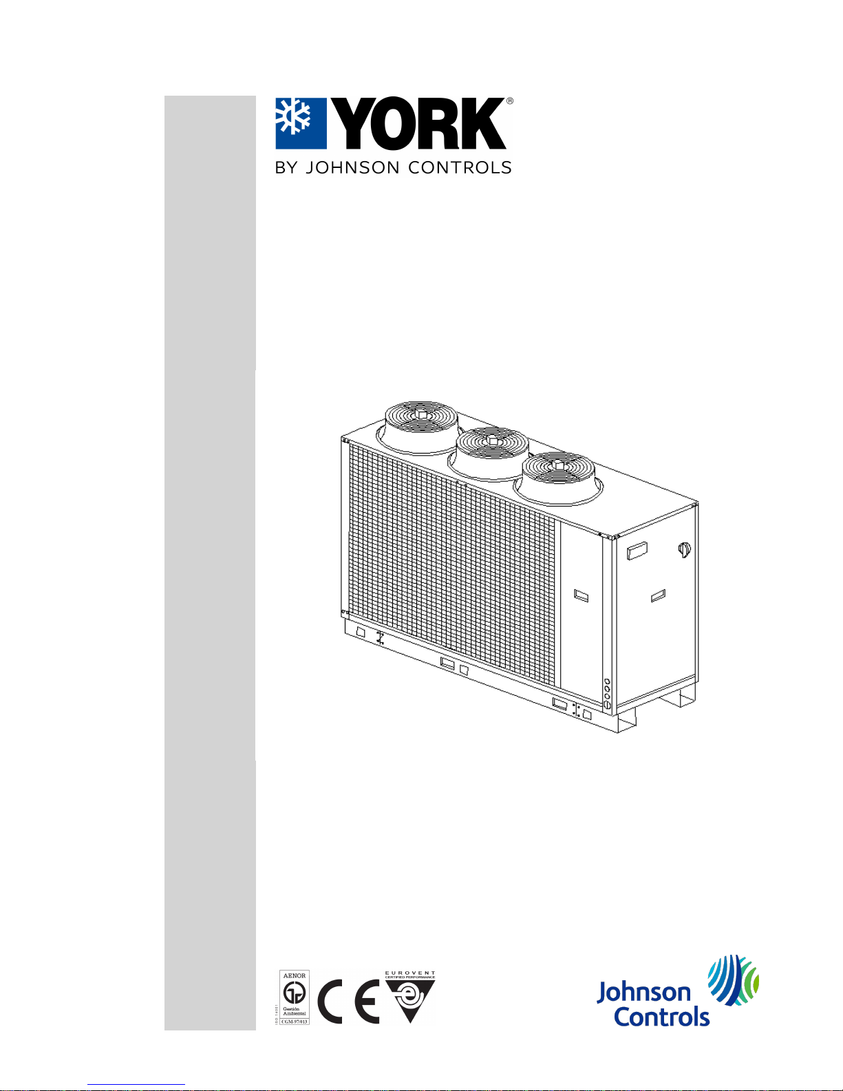
Air-condensed water chillers and
heat pumps YLCA 50, 60 and 80
User manual
Ref.: N-40289_EN 0910
Page 2

Index
1 User manual ............................................................................................................................1
1.1 General description of the unit.................................................................................................2
1.1.1 Models available and capacities...............................................................................................2
1.1.2 Technical specifications...........................................................................................................3
1.2 Operating instructions µC2 (YLCA 50, 60 and 80)...................................................................7
1.2.1 General diagram, YLCA 50, 60 and 80....................................................................................9
1.2.2 Symbols on the display..........................................................................................................10
1.2.3 Location of controls (YLCA 50, 60 and 80)............................................................................11
1.2.4 Parameters relating to sensors..............................................................................................12
1.2.5 Parameters relating to the compressor..................................................................................12
1.2.6 Operating graphics.................................................................................................................13
1.2.7 Parameters relating to fans....................................................................................................16
1.2.8 Antifreeze control configuration parameters...........................................................................17
1.2.9 Unit configuration parameters................................................................................................18
1.2.10 Alarm configuration parameters.............................................................................................19
1.2.11 Controller configuration parameters.......................................................................................20
1.2.12 Alarm table.............................................................................................................................21
1.2.13 Functions................................................................................................................................22
1.3 Regular maintenance activities for which the user is responsible..........................................23
1.3.1 Maintenance Schedule...........................................................................................................23
1.3.2 Maintenance responsibilities of the user................................................................................23
Index
i
Page 3

1
User manual
Page 4
1.1 General description of the unit
The YLCA/YLHA units are high-performance air-water chillers and heat pumps using R-410A ecological
refrigerant.
These units are designed for air conditioning or industrial applications that require cold or hot water.
They are silent and compact units, equipped with vertical air discharge axial fans, that can be installed
directly outdoors.
They are available in two versions: with and without a hydro kit, which includes a buffer tank and a high
head pressure pump.
The control system of these units is a specially programmed electronic controller to be used on air-water
chillers and heat pumps equipped with tandem compressors. Easy to use and safe, these units precision
control the water return temperature of the installation, carry out defrost cycles, modulate fan speeds
and control compressor, pump and electric heater start-up. By reading the control sensors and safety
elements, the controller protects the entire equipment against malfunctions. The system allows con‐
necting the unit to a standard RS485 monitoring network.
For further information, please see Operating Instructions.
The YLCA/YLHA units are made of proven quality components and manufactured in compliance with
standards in force (ISO 9001 certification).
1.1.1 Models available and capacities
Cool-only
model
YLCA 40 YLCA 50 YLCA 60 YLCA 80 YLCA 100 YLCA 120 YLCA 150
Cooling ca‐
pacity
39,6 52,1 60,5 77,6 99 119 151
Heat pump
model
YLHA 40 YLHA 50 YLHA 60 YLHA 80 YLHA 100 YLHA 120 YLHA 150
Cooling ca‐
pacity
37,8 52 60,5 72,2 96 114 145
Heating ca‐
pacity
38,6 52,5 59,6 74,7 104 119,6 150
Cooling capacities in kW for 12/7 °C water input /output temperature and 35°C ambient temperature.
Heating capacities in kW for 40/45 °C water input /output temperature and 7°C ambient temperature.
1
User manual
1.1 General description of the unit
2
Page 5

1.1.2 Technical specifications
These units are supplied completely factory-assembled and with all refrigerant tubing and wiring ready
for installation on site. After mounting, these units must go through an operational test with water. Re‐
frigerant leaks will also be checked during this process.
Sheeting casing
The units are made of galvanized steel sheeting and anticorrosion nuts and bolts. Panels can be removed
for access to internal components. The casing parts are painted with white RAL9001 oven-baked poly‐
merized enamel.
Compressors
Two hermetic Scroll compressors mounted in tandem on rails and antivibratory supports are used (except
for model 40, which contains one single compressor). Both compressors are connected for operation
with one single cooling circuit. Start-up is carried out by two independent starters. These compressors
are equipped with mechanical elements that protect them against high operating temperatures. The sump
heaters operate only when the compressor is inoperative.
Indoor heat exchanger
Comprises a stainless steel plate exchanger, adequately insulated by a layer of closed-cell elastomer
foam. Includes an antifreeze heater monitored by the controller. The refrigerant side of said exchanger
accepts an operating pressure of 45 bar, whereas the water side accepts 10 bar. When the unit includes
a hydro kit, maximum admissible pressure on the water side is 6 bar (adjustment of the tank safety valve).
Outdoor heat exchanger
Made up of two notched aluminium blue fin coils and grooved copper tubing mechanically expanded
within the fin assembly.
Fans
Of the axial and low sound level type. Equipped with single-phase motors with IP54 protection. These
motors allow speed control by means of a phase cut-out shifter controlled by the unit controller. This
allows unit operation at low ambient temperatures (-10°C). On cool only units with an optional low ambient
temperature kit can reach ‑18°C. On heat pumps, the fan will remain inoperative during defrosting.
Electrical and control panel
Located at the front of the unit, and with IP44 protection. The operating and control components are
factory mounted, wired and tested. The door of this control panel is equipped with a locking isolator that
turns power supply off. Inside we find the contactors for compressors and the pump, the transformer,
magneto-thermal protectors, controller electronic plates, speed control, connecting strip and the key‐
board-display with the unit controls.
Control keyboard-display
This device is accessible through an external leak-tight plastic cover. This is an easy-to-use control with
three access levels: direct, user (password) and factory (password). For further information, please see
Operating Instructions.
Cooling circuit
The cool only unit cooling circuit includes: expansion valve, filter-dryer, liquid sight glass, high and low
pressure switches, service valves for isolating the condensing unit, and Schrader valves on the high and
low sides. The heat pump model also includes, in addition, a four-way valve (energized in summer cycle
and during defrosts), retaining valves, a heat cycle expansion valve and a liquid tank. The suction tubing
is coated with closed-cell elastomer.
User manual
1
General description of the unit 1.1
3
Page 6

Hydro kit (pack)
These units include a pack assembled with the components of a hydro kit. This assembly is located within
the unit frame and does not increase the footprint of same. It includes the following components: Lined
buffer tank and with an antifreeze heater, centrifugal pump, expansion vessel charged with nitrogen at
1.5 bar, safety valve set to 6 bar, water circuit, pressure gauge, two air bleed valves, filling valve and
drain valve. Also includes a mesh filter for the water circuit. This filter is supplied loose for installation at
the most convenient point.
Flow switch
Assures sufficient water flow when the unit is in operation.
Protecting grids
To protect the coils from possible impacts. Made of steel rods and painted with oven baked polymerized
white enamel (RAL9001).
1
User manual
1.1 General description of the unit
4
Page 7

Options and accessories
Units without hydro kit
This includes the elements described in the previously mentioned specifications, less the hydro kit (pack).
The water circuit includes an air bleed valve. Connections are ready for on-site installation.
Two pumps
Accessory available with models 50 to 100 with hydro kit. The second pump becomes operative when
the magnetothermal protector of the first pump is activated (models 50, 60 and 80), or through the con‐
troller program (models 100, 120 and 150).
Water filter
Supplied as a standard element on units including the hydro kit. Stainless steel mesh with 1 mm. diameter
perforations. Optional on units not including the hydro kit. The warrantee of the unit will not be valid if a
water filter has not been installed.
Remote control
Wall-mounted remote control unit with keyboard for cool /heat and ON /OFF functions. Includes power
supply, alarm and cool /heat LEDs. Maximum cable length: 50 m.
Remote terminal
For total access and control of the system by means of the display and buttons. It allows for selection of
cool, heat and off functions. Operating parameters can also be modified and the system can also be
supervised. Can be installed at a maximum distance of 1040 m.
BMS connections
By means of a serial board, it is possible to connect the system to a standard RS485 monitoring network.
Low noise level units (LN)
Include anti-noise covers mounted on the compressors and sound isolating plates, covering the com‐
pressor chamber.
Static starter
For the soft motor start. Specially designed for Scroll compressors. (Maximum outdoor temperature:
50℃).
User manual
1
General description of the unit 1.1
5
Page 8
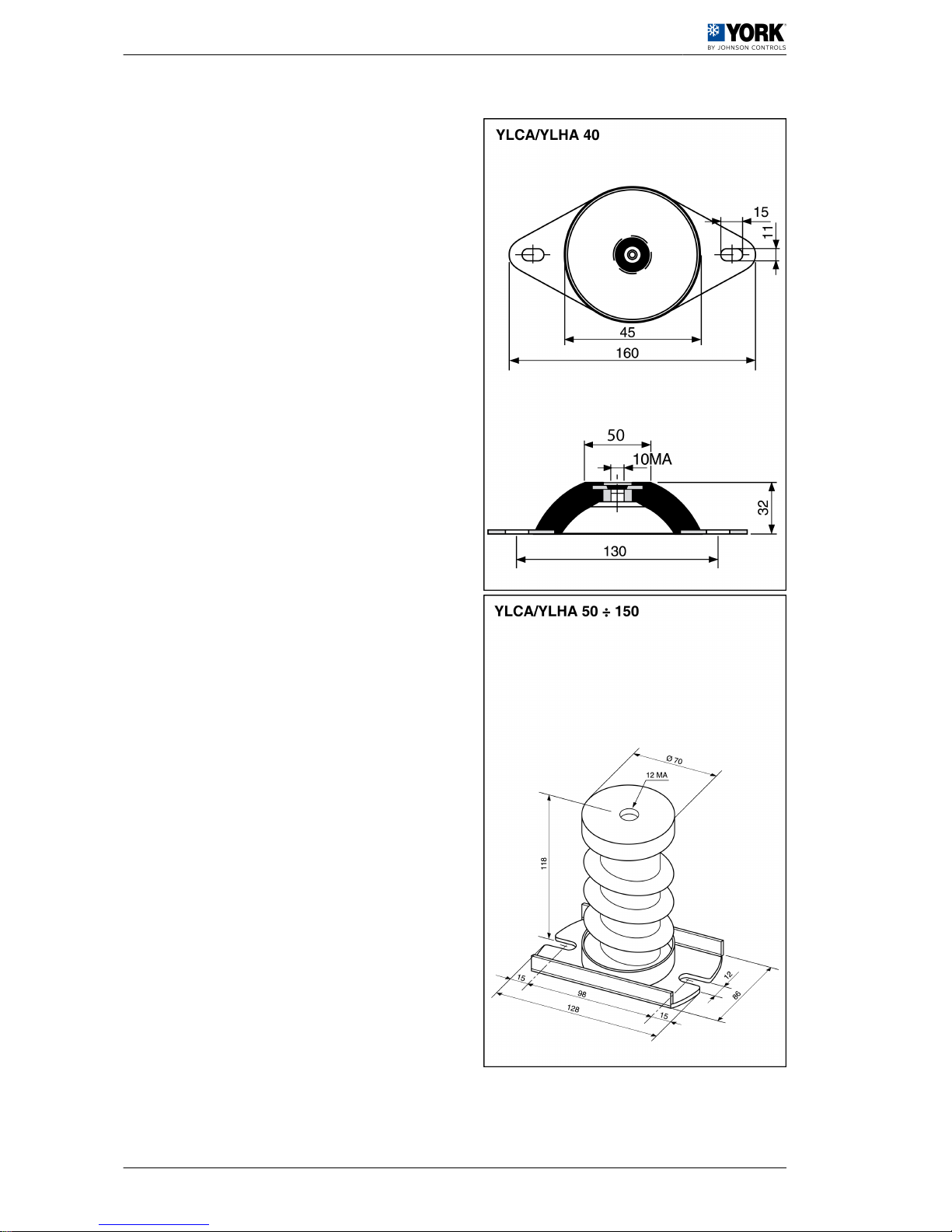
Antivibratory supports
Whenever necessary to reduce vibrations and noise
produced by the unit to a maximum, a set of steel
spring antivibratory supports can be used. These
should be installed between the chassis support of the
unit and the base or floor on which it is to sit.
This base must be solid and dimensioned in accord‐
ance with the load to be supported.
The antivibratory support accessory for models YL‐
CA/YLHA 40, 50 and 60 includes 4 units, whereas for
models YLCA/YLHA 80, 100, 120 and 150 includes 6.
These spring supports should be distributed and fas‐
tened in the drilled holes at the base of the chiller, the
location of which is detailed in the General Dimen‐
sions section.
1
User manual
1.1 General description of the unit
6
Page 9

1.2 Operating instructions µC2 (YLCA 50, 60 and 80)
DESCRIPTION OF THE CONTROL UNIT
This is a multipurpose controller specially programmed for use with air-water chillers and heat pumps
equipped with a tandem compressor, two power stages and a single cooling circuit.
Main functions
• Water temperature control (at inlet or outlet, as per parameter r6).
• Defrost cycle management.
• System operating and safety management.
• Fan speed control.
• Alarm management.
• Connection for supervision and remote assistance (accessory serial connection RS485).
Devices controlled
• Compressor
• Fans
• Four-way valve
• Water pump
• Alarm device
• Heaters
STANDARD COMPONENTS
Base control module for the system and the first compressor.
This is the central nucleus that processes the signals coming from the sensors and protection elements
of the entire system to control its active elements: compressors and fans, four-way valve, water circulating
pump, alarm relay and antifreeze heater. Power supply 24 Vac.
It can also be used for access and control of the system by means of the display, buttons and LEDs
available. It allows for selection of cool, heat and off functions. Operating parameters can also be modi‐
fied, and the system can also be supervised.
Fan speed control module
Operates by phase cut-off. Includes fuse
NTC and ratiometric (pressure) sensors
3 NTC sensors are used to read system temperatures and a ratiometric pressure transducer (B4) to read
refrigerant pressure inside the coil:
• B1. Controls the set point. Reads water temperature at exchanger inlet.
• B2. Antifreeze control. Reads water temperature at exchanger discharge.
• B3. Controls the dynamic set point. Reads outdoor air temperature.
• B4. Fan speed and defrost cycle control. Reads refrigerant pressure inside the coil.
Parameters
The set of parameters that configure the operating program of the unit is divided into four levels (Factory,
Super User, User and Direct), depending upon the function of each parameter and the user’s access
level. The parameters of each level can be modified from that same level, as well as lower level param‐
eters.
Factory Level
Accessible with the Factory password. Allows configuration of all unit parameters.
Super User Level
Accessible with the Super User password. Allows setting Super User, User and Direct parameters.
User Level
Accessible with password 22. Allows access to all parameters the user normally sets.
User manual
1
Operating instructions µC2 (YLCA 50, 60 and 80) 1.2
7
Page 10

Direct Level
Accessible without a password. Allows for reading of the values detected by the sensors, as well as other
system values. Can be used by the user without affecting unit operation.
General
Modification of the parameters that affect basic unit configuration should be made with the controller in
Standby position.
1
User manual
1.2 Operating instructions µC2 (YLCA 50, 60 and 80)
8
Page 11
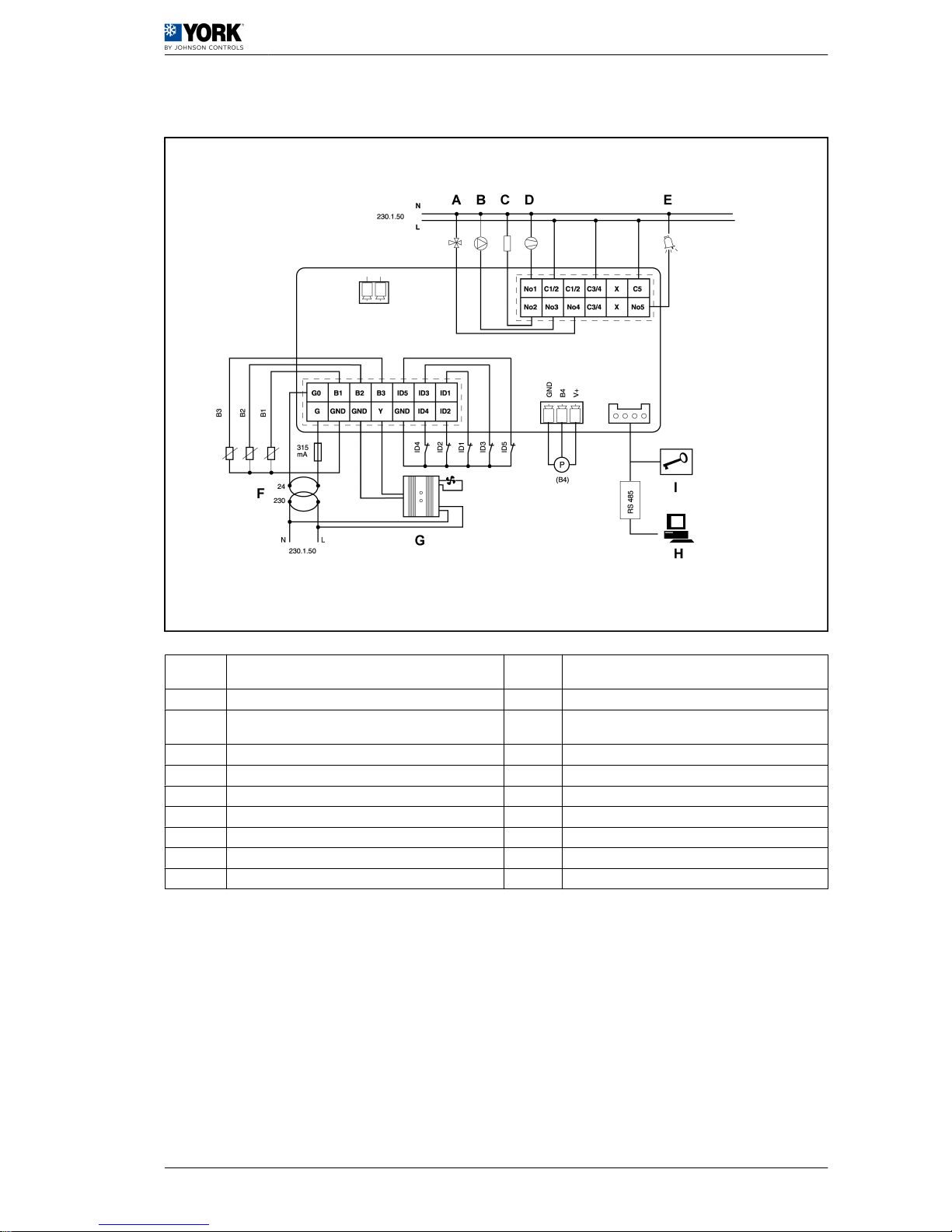
1.2.1 General diagram, YLCA 50, 60 and 80
A Compressor 2 B2
Water outlet temperature sensor (Antifreeze pro‐
tection)
B Pump B3 Outdoor temperature sensor (Dynamic set point)
C Heater B4
Radiometric pressure sensor (Fan speed and de‐
frost control)
D Compressor 1 ID1 Water flow switch
E Alarm ID2 Fan heat switches
F 230 / 24 transformer ID3 High-pressure switch
G Fan speed control ID4 Low-pressure switch
H Communication ID5 Remote ON / OFF
I Programmable key N Neutral
B1 Water inlet temperature sensor (Control set point) L Phase
User manual 1
Operating instructions µC2 (YLCA 50, 60 and 80) 1.2
9
Page 12
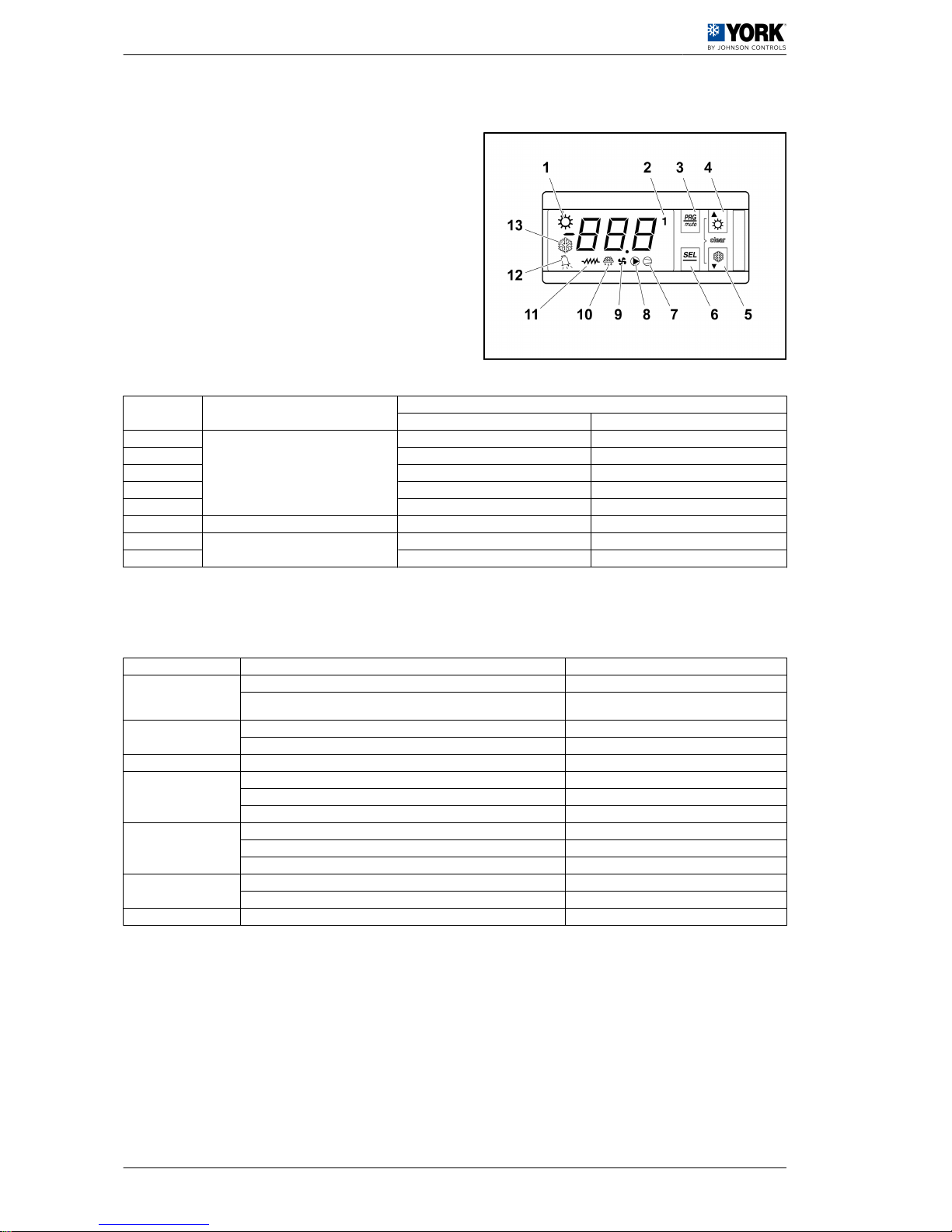
1.2.2 Symbols on the display
The display has three figures in green, plus the sign
and one decimal. It also shows the symbols of the
functions selected in orange (the alarm symbol is red).
Button Colour
Meaning
LED permanently lit LED flashing
-2-
Orange
Compressor operating * Timing start-up
-7- Compressor on call -
-8- Water pump operating -
-9- Fans operating -
-10- Defrost active -
-12- Red Alarm activated -
-13Orange
Cool cycle -
-1- Heat cycle -
(*) Operational compressor number
Button Unit status Pressing
-3-
Loads default values Applies voltage when pressed
Returns to superior sub-group within programming area until output of same (ex‐
cept changes in E2PROM)
Press once
-6-
Access to Direct parameters Press for 5 seconds
Selects a Direct parameter and shows its value / Confirms parameter changes Press once
-3- + ‑6- Parameter programming with password Press for 5 seconds
-4-
Selection of higher parameter within the programming area Press once or keep pressed down
Increase value Press once or keep pressed down
Selection of heat function from standby position and vice versa (P6=1) Press for 5 seconds
-5-
Selection of lower parameter within the programming area Press once or keep pressed down
Reduce value Press once or keep pressed down
Selection of cool function from standby position and vice versa (P6=1) Press for 5 seconds
-4- + ‑5-
Manual alarm reset Press for 5 seconds
Clears hour counters (within programming area) Press for 5 seconds
-6- + ‑1- Forced manual defrost Press for 5 seconds
1 User manual
1.2 Operating instructions µC2 (YLCA 50, 60 and 80)
10
Page 13
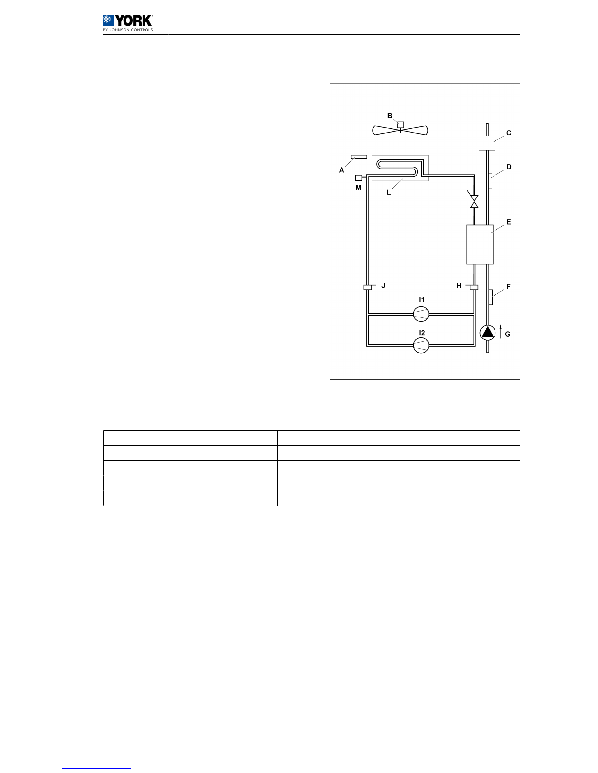
1.2.3 Location of controls (YLCA 50, 60 and 80)
A Temperature sensor (B3) H
Low-pressure switch
(LP)
B Fan I1 Compressor 1
C Flow switch (FS) I2 Compressor 2
D
NTC water outlet sensor
(B2)
J
high-pressure switch
(HP)
E Indoor heat exchanger L
Outdoor heat exchang‐
er
F
NTC water inlet sensor
(B1)
M Pressure sensor (B4)
G Pump
Parameter tables
The following tables show the parameters and their values, divided into groups:
Parameter level codes Supervision variables
D Direct R/W Read/write parameter
U User R Read-only parameter
S Super user
F Factory
User manual 1
Operating instructions µC2 (YLCA 50, 60 and 80) 1.2
11
Page 14
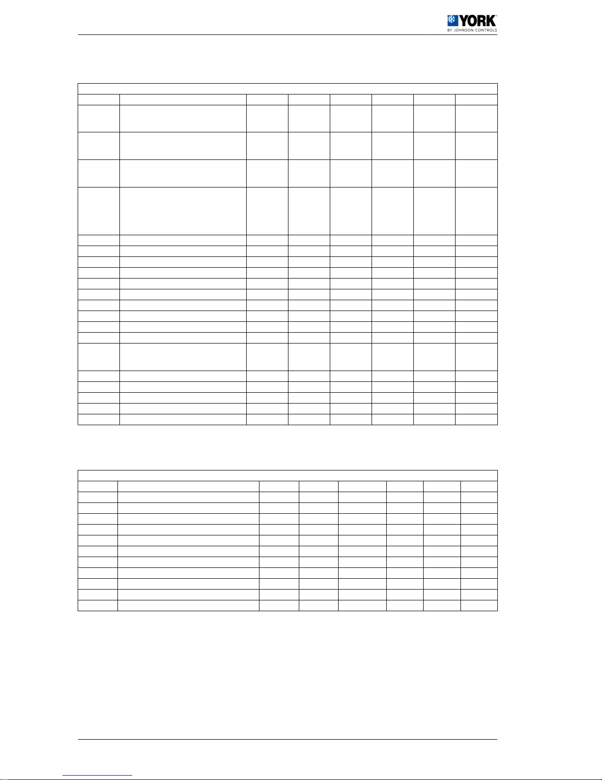
1.2.4 Parameters relating to sensors
Parameters relating to sensors
Display Description Level VS Unit Max. Min. Value
/01
NTC B1 sensor (water inlet):
0= Absent (function not available
1= Present
F 1 (R/W) - 1 0 1
/02
NTC B2 sensor (water outlet):
0=Always ON (function not available)
1= Present
F 2 (R/W) - 1 0 1
/03
NTC B3 sensor:
1= Condensation sensor
2= Outdoor sensor
F 14 (R/W) - 1 0 2
/04
B4 sensor:
0= Absent
1= ON/OFF
2= Outdoor NTC sensor
3= Ratiometric 5 Vdc
F 15 (R/W) - 3 0 3
/09 Minimum input voltage F 18 (R/W) 0.01 Vdc /10 0 50
/10 Maximum input voltage F 19 (R/W) 0.01 Vdc 500 /09 450
/11 Minimum pressure F 1 (R/W) bar /12 0 0
/12 Maximum pressure F 2 (R/W) bar 99,9 /11 45
/13 B1 sensor calibration F 3 (R/W) °C 12 -12 0
/14 B2 sensor calibration F 4 (R/W) °C 12 -12 0
/15 B3 sensor calibration F 5 (R/W) °C 12 -12 0
/16 B4 sensor calibration F 6 (R/W) bar 12 -12 0
/21 Digital filter U 20 (R/W) - 15 1 4
/22 Input limitation U 21 (R/W) - 15 1 8
/23
Measuring unit
0=C
1=1F
U 5 (R/W) - 1 0 0
b00 Sensor viewed on display U 24 (R/W) - 7 0 0
b01 Value read by sensor B1 D 70 (R) °C - - -
b02 Value read by sensor B2 D 71 (R) °C - - -
b03 Value read by sensor B3 D 72 (R) °C - - -
b04 Value read by sensor B4 D 73 (R) °C/bar - - -
1.2.5 Parameters relating to the compressor
Parameters relating to the compressor
Display Description Level VS Unit Max. Min. Value
c01 Minimum operating time U 25 (R/W) Seconds 999 0 120
c02 Minimum stoppage time U 26 (R/W) Seconds 999 0 60
c03 Time between start-ups of one compressor U 27 (R/W) Seconds 999 0 300
c06 Start-up timing U 30 (R/W) Seconds 999 0 10
c07 Compressor start-up delay with regard to the pump U 31 (R/W) Seconds 150 0 20
c08 Pump stoppage delay with regard to the compressor U 32 (R/W) Minutes 150 0 1
c10 Operating hour counter for compressor D 90 (R) Hours 800 0 -
c14 Operating hour counter for compressor maintenance U 34 (R/W) Hours 100 0 0
c15 Operating hour counter for pump D 94 (R/W) Hours 800 0 -
c17 Minimum time between pump start-ups U 35 (R/W) Minutes 150 0 5
c18 Minimum operating time for pump U 36 (R/W) Minutes 15 0 1
1 User manual
1.2 Operating instructions µC2 (YLCA 50, 60 and 80)
12
Page 15
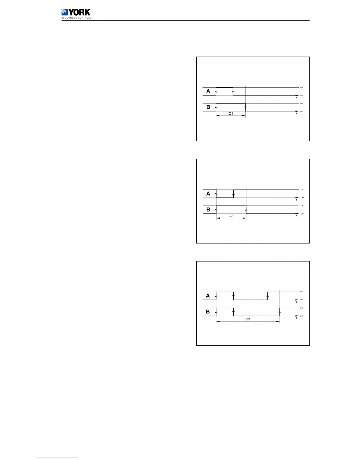
1.2.6 Operating graphics
Min. operating time of a compressor
A Signal
B Compressor
Min. stoppage time of a compressor
A Signal
B Compressor
Min. time between compressor start-ups
A Signal
B Compressor
User manual 1
Operating instructions µC2 (YLCA 50, 60 and 80) 1.2
13
Page 16
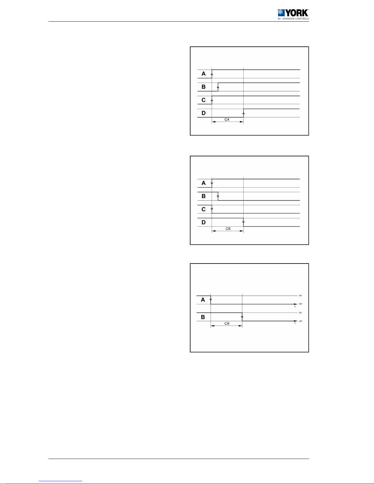
Min. time between start-up of two compressors
A Signal 1 C Compressor 1
B Signal 2 D Compressor 2
Time between stoppage of two compressors
A Signal 1 C Compressor 1
B Signal 2 D Compressor 2
Compressor / pump stoppage delays
A Compressor
B Pump
1 User manual
1.2 Operating instructions µC2 (YLCA 50, 60 and 80)
14
Page 17
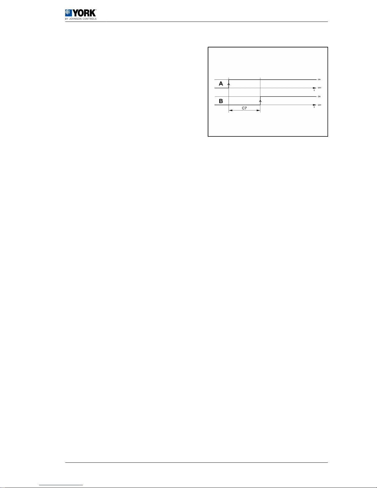
Pump / compressor start-up delays
A Pump
B Compressor
User manual 1
Operating instructions µC2 (YLCA 50, 60 and 80) 1.2
15
Page 18
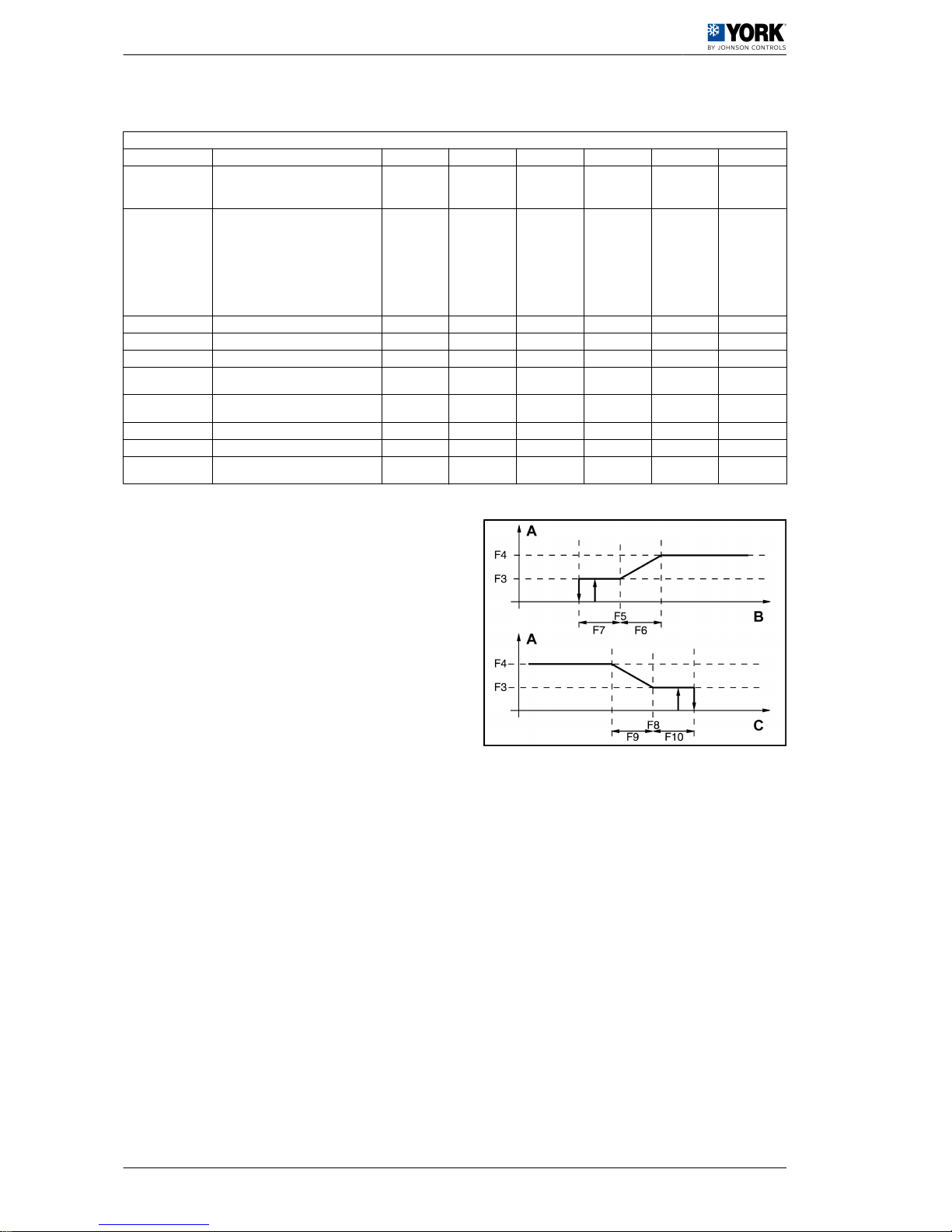
1.2.7 Parameters relating to fans
Parameters relating to fans
Parameters Description Level VS Unit Max. Min. Value
F01
Fan outlet:
0= Absent (function not available
1= Present
F 10 (R/W) 1 0 1
F02
Operating mode:
0=Always ON (function not available)
1= parallel to the compressor (function not
available)
2=ON/OFF operation (function not avail‐
able)
3= parallel to the compressor and speed
adjustment
U 48 (R/W) 3 0 3
F03 Minimum Triac voltage F 49 (R/W) step F04 0 35
F04 Maximum Triac voltage F 50 (R/W) step 100 F03 92
F05 Cool cycle minimum speed pressure + 24 (R/W) bar 80 -40 22,2
F06
Cool cycle maximum speed pressure dif‐
ferential
F 26 (R/W) bar 50 0 3,7
F07
Cool cycle fan stoppage pressure differ‐
ential
F 28 (R/W) bar 50 0 6,5
F11 Fan start-up time F 51 (R/W) Seconds 120 0 10
F12 Triac impulse duration F 52 (R/W) Seconds 10 0 2
F14
Fan operating when starting with high am‐
bient temperature
U 91 (R/W) Seconds 999 0 30
A Fan speed
B Condensing temperature
C Evaporating temperature
1 User manual
1.2 Operating instructions µC2 (YLCA 50, 60 and 80)
16
Page 19
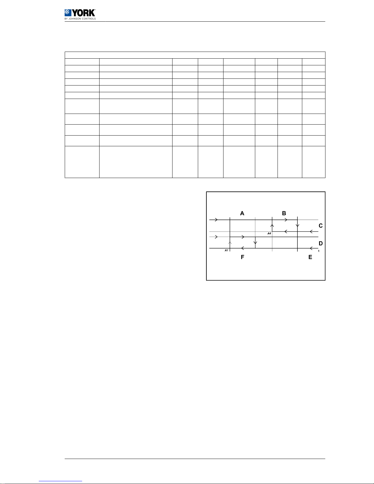
1.2.8 Antifreeze control configuration parameters
Antifreeze control configuration parameters
Parameters Description Level VS Unit Max. Min. Value
A01 Antifreeze control set point temperature U 11 (R/W) °C - A07 3
A02 Antifreeze reset differential U 12 (R/W) °K 50 0,3 5
A03 Antifreeze alarm bypass time U 22 (R/W) Seconds 150 0 0
A04 Antifreeze heater activation temperature U 13 (R/W) °C r16 A01 3
A05 Antifreeze heater activation differential U 14 (R/W) °K 50 0,3 2
A06
Backup heater control sensor:
0= Control sensor
1= Antifreeze sensor
F 6 (R/W) - 1 0 0
A07
Minimum level antifreeze control set point tem‐
perature
U 15 (R/W) °C 79 -40 3
A08
Heating heater activation set point tempera‐
ture
U 16 (R/W) °C r15 A01 3
A09
Heating heater deactivation set point temper‐
ature differential
U 17 (R/W) °C 50 0,3 3
A10
Automatic start-up by antifreeze alarm (unit in
standby):
0= Function disabled
1= Water pump+heater
2= Water pump + heater + compressor (heat
pumps only)
3= Heater
U 23 (R/W) 3 0 1
A
Antifreeze reset differen‐
tial (A2)
D Antifreeze alarm
B
Antifreeze heater activa‐
tion differential (A5)
E
Antifreeze heater acti‐
vation temperature (A4)
C Heaters F
Antifreeze set point
temperature (A1)
User manual 1
Operating instructions µC2 (YLCA 50, 60 and 80) 1.2
17
Page 20
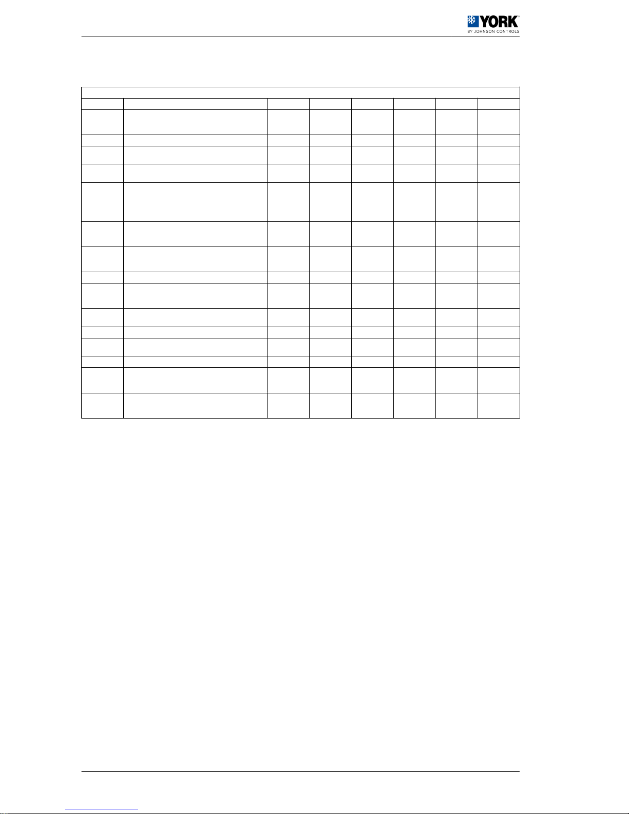
1.2.9 Unit configuration parameters
Unit configuration parameters
Display Description Level VS Unit Max. Min. Value
H01
Unit model:
2= Water chiller
3= Air-water heat pump
F 54 (R/W) 2
H02 Number of vent circuits (do not modify this parameter) F 12 (R/W) 0
H03
No. of evaporating units present (do not modify this
parameter)
F 13 (R/W) 0
H04
No. of compressors per circuit (do not modify this pa‐
rameter)
F 55 (R/W) 1
H05
Pump operation:
0= Absent
1= Always ON
2= ON upon controller call
3= ON upon controller and time call
F 56 (R/W) 3 0 1
H06
COOL/HEAT digital input:
0= Absent
1= Present
U 14 (R/W) 1 0 0
H07
ON/OFF digital input:
0= Absent
1= Present
U 15 (R/W) 1 0 0
H08 Network configuration (do not modify this parameter) F 57 (R/W) 3 0 0
H09
Keyboard locked:
0= Disabled
1= Enabled
U 16 (R/W) 1 0 1
H10
Serial direction for monitoring:
0= Future use as terminal
U 58 (R/W) 200 1 1
H11 Output configuration (not selectable) F 59 (R/W) 3 0 1
H12
4-way valve logic operation. Activated in cold cycle (do
not modify this parameter)
F 60 (R/W) 3 0 0
H21 Second pump function (do not modify this parameter) F 62 (R/W) 4 0 0
H22
Default parameter loading disabled:
0= Disabled
1= Enabled
F 18 (R/W) 1 0 1
H23
Modbus protocol setting:
0= Disabled
1= Enabled
F 11 1 0 0
1 User manual
1.2 Operating instructions µC2 (YLCA 50, 60 and 80)
18
Page 21
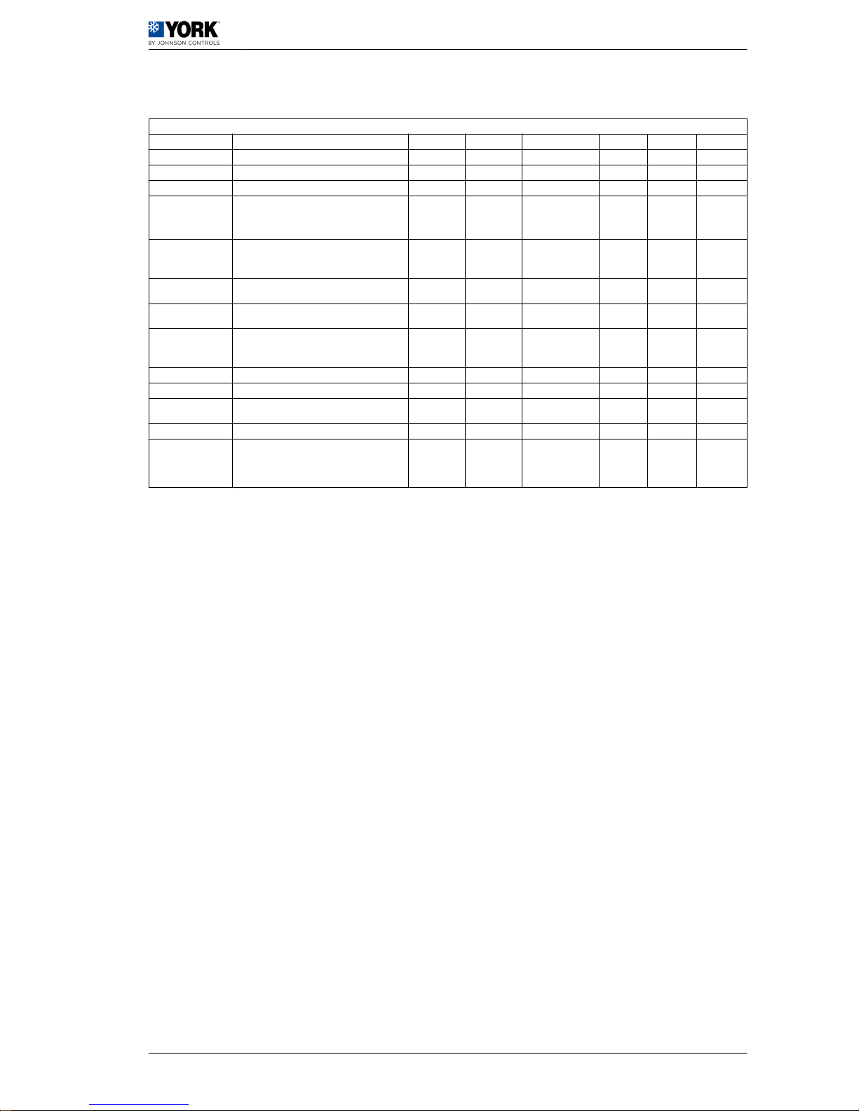
1.2.10 Alarm configuration parameters
Alarm configuration parameters
Parameters Description Level VS Unit Max. Min. Value
P01 Alarm delay by flow switch at start-up. U 63 (R/W) Seconds 150 0 20
P02 Alarm delay by flow switch with unit in operation. U 64 (R/W) Seconds 120 0 5
P03 Alarm delay by low-pressure switch at start-up. U 65 (R/W) Seconds 200 0 60
P05
Alarm reset
6= High and low-pressure switch manual reset at
third activation in one hour. Antifreeze control is
manually reset
F 67 (R/W) 6
P06
Cool and heat cycle symbols.
1= "Sun" heat cycle, "Snowflake" cool cycle
0= "Sun" cool cycle, "Snowflake" heat cycle
F 19 (R/W) 1 0 1
P08
Digital input 1 for flow switch Do not modify this
parameter
F 69 (R/W) 1
P09
Digital input 2 for the remote Cool/Heat function.
Do not modify this parameter
F 70 (R/W) 9
P15
Low-pressure alarm selection.
0= Inoperative with the compressor OFF
1= Operative with the compressor OFF
F 76 (R/W) 1 0 1
P16 High-temperature alarm for return water U 38 (R/W) °C 80 -40 30
P17 High-temperature delay at start-up U 77 (R/W) Minutes 250 0 30
P18
High-pressure alarm by transducer
0= function disabled
F 39 (R/W) bar 99,9 0,1 41
P19 Low-temperature alarm for return water U 40 (R/W) °C 80 -40 10
P20
Alarm activation for high and low water temper‐
ature at start-up.
1= function enabled
0= function not enabled
U 20 (R/W) 1 0 0
User manual 1
Operating instructions µC2 (YLCA 50, 60 and 80) 1.2
19
Page 22
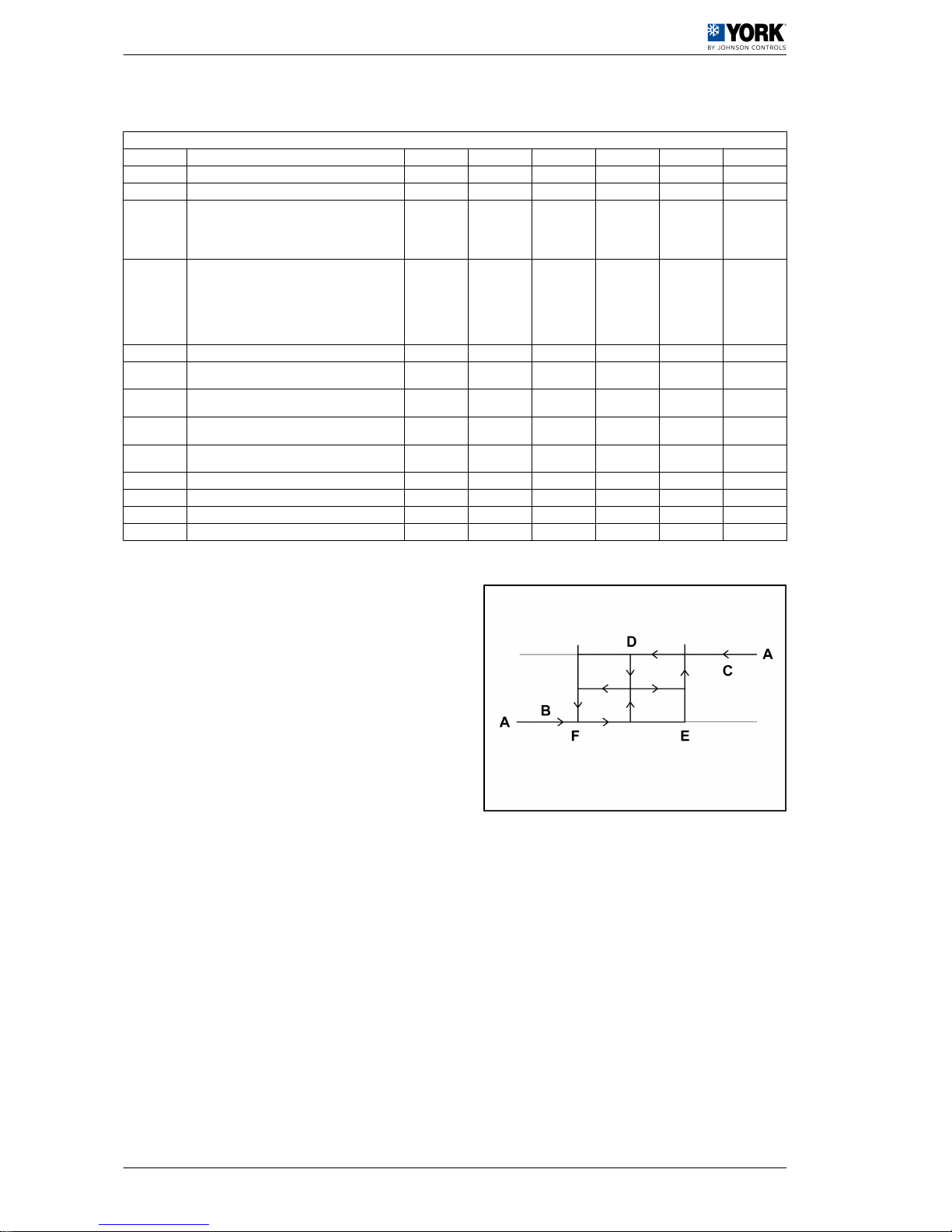
1.2.11 Controller configuration parameters
Controller configuration parameters
Display Description Level VS Unit Max. Min. Value
r01 Cool cycle set point temperature U 41 (R/W) °C r14 r13 12
r02 Cool set point temperature differential U 42 (R/W) °C 50 0,3 2
r05
Compressor rotation
0= Disabled
1= FIFO type
2= Per operating hours
F 78 (R/W) 2 0 2
r06
Type of adjustment 0= Proportional. Input temperature.
1= Proportional+neutral zone. Input temp.
2= Proportional. Output temperature
3= Proportional+neutral zone. Output temp.
4= By time+dead zone. Output temperature (chillers
only)
F 79 (R/W) 4 0 0
r07 Neutral zone differential F 45 (R/W) °C 50 0 1
r08
(If r06=4 only) Maximum activation time. Output tem‐
perature.
F 80 (R/W) Seconds 999 r09 120
r09
(If r06=4 only) Minimum activation time. Output tem‐
perature.
F 81 (R/W) Seconds 999 c04 100
r10
(If r06=4 only) Maximum deactivation time. Output tem‐
perature.
F 82 (R/W) Seconds 999 r11 120
r11
(If r06=4 only) Minimum deactivation time. Output tem‐
perature.
F 83 (R/W) Seconds 999 c05 100
r12 (If r06=4 only) Compressor deactivation differential. F 46 (R/W) °C 50 0 1
r13 Cool cycle minimum set point temperature U 47 (R/W) °C r14 -40 6
r14 Cool cycle maximum set point temperature U 48 (R/W) °C 80 r13 20
r15 Heat cycle minimum set point temperature U 49 (R/W) °C r16 -40 25
A Temperature D Differential /2 (r02 / 2)
B First compressor E
COOL set point (r01) + Differ‐
ential (r02)
C
Second compres‐
sor
F COOL set point (r01)
1 User manual
1.2 Operating instructions µC2 (YLCA 50, 60 and 80)
20
Page 23
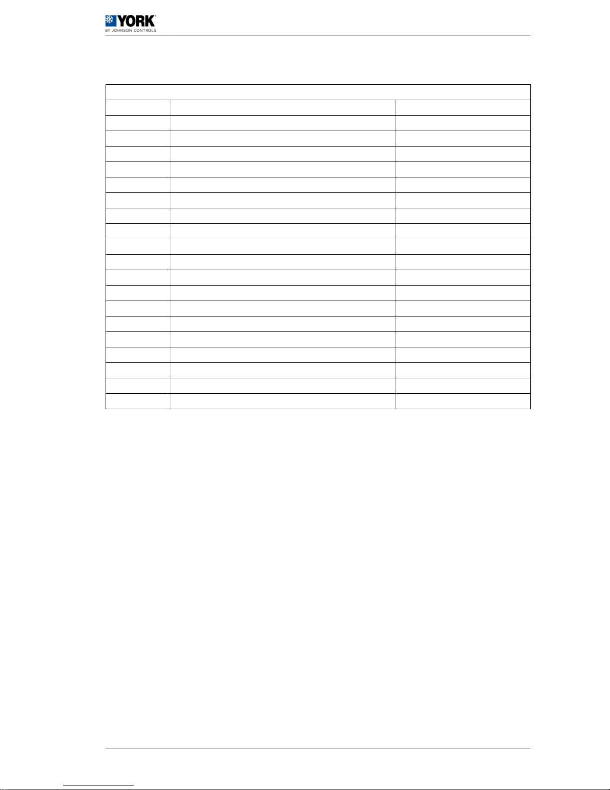
1.2.12 Alarm table
Alarm table
Display Alarm type Reset
A1 Antifreeze alarm Manual
Aht High temperature at start-up (if activated, P20=1) Automatic
ALt Low temperature at start-up (if activated, P20=1) Automatic
E1 B1 sensor Automatic
E2 B2 sensor Automatic
E3 B3 sensor Automatic
E4 B4 sensor Automatic
ELS Low supply voltage Automatic
EHS High supply voltage Automatic
EPr Eprom. error. Unit operating. Automatic
EPb Eprom. error. At start-up Automatic
EL 1-2 Problem at fan voltage control Automatic
FL Flow switch / pump protector Manual
Hc1/Hc2 Compressor maintenance alarm Automatic
HP High pressure Manual
Ht High water temperature alarm Automatic
LP Low pressure Manual
PC1 Compressor partialisation (high pressure) Automatic
tC1 Fan heat switches Manual
User manual 1
Operating instructions µC2 (YLCA 50, 60 and 80) 1.2
21
Page 24

1.2.13 Functions
Alarm reset
Pressing the UP and DOWN keys for 5 seconds cancels alarms present in the memory. At the same
time, the alarm message disappears from the display and the alarm relay is deactivated.
Clearing hour counters
While reading compressor or pump (c10, c11 and c15) operating hours, said counters can be cleared
by pressing the UP and DOWN keys simultaneously.
Pump operation
4 operating modes can be selected in accordance with the value given to parameter H5. H5=0 (pump
disabled). H5=1 (pump permanently on), H5=2 (pump ON controlled by the regulator or in parallel with
the compressor), H5=3 (pump goes on and off at regular intervals, independent of compressor operation)
(parameters c17 and c18).
Calibration of sensors
If necessary, sensors can be calibrated by using parameters /13, /14, /15, /16, /19 and /20. See Table
Parameters relating to sensors, see on page 12
.
Remote ON/OFF
A remote ON/OFF inlet can be connected between terminals D5 and B on the connecting strip. To activate
said inlet, a value of 1 should be given to parameter H07 (H07= 1). With this inlet open the unit is OFF;
when closed, the unit is ON. This option does not disable the ON/OFF function of the keyboard.
Partialisation of compressors in (HP Prevent) high pressure
This function is activated if P04 = 1. If for any reason the high pressure is near the disconnecting point
(P18-0.5 bar), this control deactivates one of the compressors and waits 10 seconds. After this interval,
if the alarm persists, the unit will stop. If, on the other hand, the alarm disappears, the unit will continue
to operate with one single compressor. In this situation, the message PC1 appears on screen. This
condition will remain activated until the pressure drops below the F5 + F6 value. In this case, the unit
recovers the previously deactivated compressor.
1
User manual
1.2 Operating instructions µC2 (YLCA 50, 60 and 80)
22
Page 25

1.3 Regular maintenance activities for which the user is respon‐
sible
1.3.1 Maintenance Schedule
The air conditioning unit is designed to require as little maintenance as possible. Nevertheless, to ensure
smooth operations with a minimal use of electricity, a long working life and compliance with the regula‐
tions of each country, regular maintenance inspections must be made.
Johnson Controls Inc. shall not be considered responsible for any damage caused by improper mainte‐
nance of the unit, which includes anything inconsistent with that described in this document or others
specifically provided with the unit.
To make them easier, maintenance tasks have been grouped by time intervals in a series of tables.
Maintenance responsibilities of the user, see on page 23
.
1.3.2 Maintenance responsibilities of the user
Like any other machine, the HVAC unit requires regular maintenance, as the wear to which some of its
parts are subjected can effect its mechanical reliability and the safety of those responsible for its main‐
tenance.
In compliance with current regulations, the unit must be regularly inspected and the results recorded on
the forms provided by the Labour and Health Authorities of the country where the HVAC unit is installed.
Users cannot access this form to perform maintenance and upkeep tasks on the unit.
There is no intent for the user to perform any maintenance tasks on the HVAC unit.
User manual
1
Regular maintenance activities for which the user is responsible 1.3
23
Page 26
D A N G E R
It is strictly prohibited for the user to carry out any maintenance or upkeep tasks on the HVAC unit.
This appliance is not destined for use by people (including children) with limited physical, sensorial or
mental capacities, or without adequate experience or knowledge, unless they have received instructions
or been supervised in the use of the appliance by an individual responsible for their safety.
Children must be supervised at all times to ensure that they do not play with the appliance.
Only trained Johnson Controls Inc. personnel with the necessary means and tools may carry out main‐
tenance and upkeep work on the unit.
Trained personnel must be aware of the health and safety regulations and procedures applicable to
HVAC units. They should also be aware of general procedures and those applying specifically to this
unit.
Contact a Johnson Controls Inc. Authorised Technical Assistance Service for scheduled maintenance
on this unit.
PRODUCT DISPOSAL
According to Directive 2002/96/EC of the European
Parliament and of the Council of 27 January 2003, the
presence of the symbol on the product or in the docu‐
ments included with the product indicates that this
product is classified, according to current law, as an
electrical and electronic device and, therefore, this
product cannot be dealt with at the end of its working
life as domestic or urban waste.
The product must be taken to collection points for the
recycling of waste electrical and electronic equip‐
ment.
The appropriate management, reuse, assessment
and recycling of these products protect human health
and the environment.
1
User manual
1.3 Regular maintenance activities for which the user is responsible
24
 Loading...