

Page 1
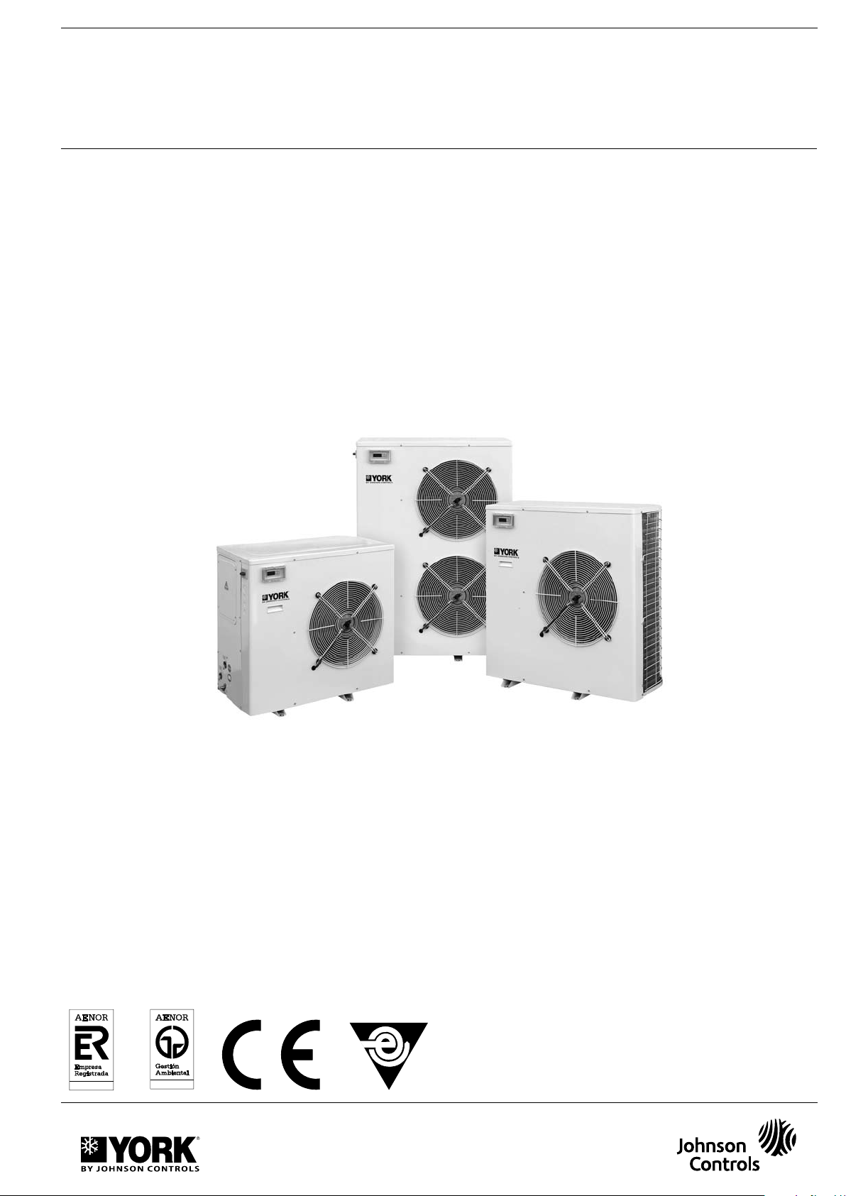
YLCA/YLHA PLUS 5 to 27 R-410A
ER-0028/1991
IS O 90 0 1
Technical Information
Ref: N-27723 0309M
Johnson Controls Manufacturing España. S.L. is participating in the EUROVENT Certification
Program.
Products are as listed in the EUROVENT Directory of Certified Products. in the program AC1.
AC2. AC3. LCP and FC.
The LCP program covers air condensed water chillers and heat pumps of up to 600 kW.
Page 2

Page 3

Index
General Information
- Nomenclature 5
- General description 5
- Models available and capacities 5
- Features and advantages 6
- Dynamic set point and suppression of buffer tank 6
Technical Specifications 6
- Accessories and options 7
- Physical data. cool only units 8
- Physical data. heat pump units 9
- Operation, cooling and hydraulic diagram,
heat pump unit YLHA PLUS 5 to 15 10
- Operation, cooling and hydraulic diagram,
heat pump unit YLHA PLUS 20 and 27 11
- Operation, cooling and hydraulic diagram,
cool only unit YLCA 12
- Table 1. Cooling capacities YLCA 5 to 27 13
- Table 2. Cooling capacities YLCA 5 to 27
(35% ethylene glycol) 14
- Table 3. Cooling capacities YLHA PLUS 5 to 27 15
- Table 4. Cooling capacities YLHA PLUS 5 to 27
(35% ethylene glycol) 16
- Table 5. Heating capacities YLHA PLUS 5 to 27 17
- Table 6. Available pressure for hydraulic circuit
(without filter installed) 18
- Table 7. Pressure drops of filters 19
- Table 8. Correcting factors for other glycol
concentrations 19
- Table 9. Sound power spectrum 19
Selection guide (YLCA and YLHA PLUS) 20
Page
- Transportation 23
5
- Handling 23
- Warning signs 23
- Location 24
- Location of several units 24
- Fastering the unit 24
- Orientation 24
- Clearances 24
Wiring 25
- Electrical connections 25
- Rotational direction of Scroll compressors 25
- Hydraulic connections 25
- General dimensions mm and hydraukic connections 26 - 28
- Minimum technical clearances 29
- Wiring diagram 30 - 34
- Wiring 35
- Electrical characteristics 36
- Limits of use 36
- Prior to final approval of the installation 36
Operating instructions µC2 (Rev.1016) 37
- Control unit description 37
- Standard components 37
- General diagram 38 - 39
- Simbols on the display 40
- Functions of remote control unit buttons 40
- Location of controls 41
- Parameter tables 41 - 51
- Temperature/resistance characteristics of the NTC
control probes 52
Page
- Necessary information 20 - 21
- Selection guide with glycol 21 - 22
Installation instructions 23
- Inspection 23
- Environmental protection 23
- Elimination of the unit 23
- Safety 23
Accessories 53 - 67
- Remote terminal 53
- Remote control unit 56
- Buffer tank 57 - 59
- 115 Litre Buffer Tank 60 - 62
- High pressure fan 63 - 64
- Low ambient temperature kit 65
- Tray heater 66
- Compressor heater YLHA 5 - 15 67
3
Page 4

Page 5
General Information
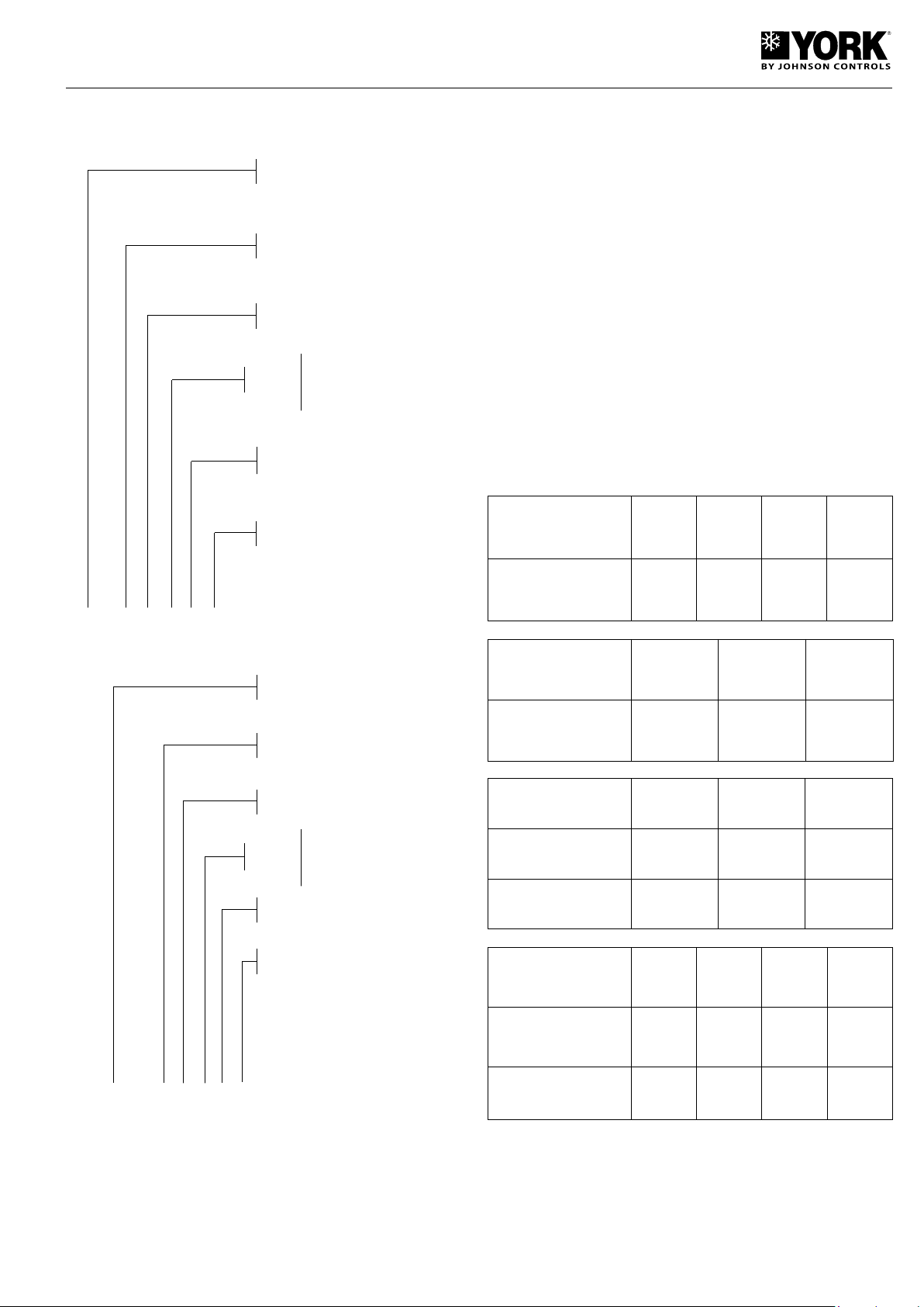
Nomenclature
Voltage
Air/water water chiller with
axial fans
Approximate cooling capacity
in kW
R-410A Version
M (single-phase 230.1.50)
T (three-phase 400.3.50)
With hydro kit (pack)
applications that require cold or hot water. They are silent
and compact units, equipped with axial fans, and can be
installed directly outdoors. Buffer tanks are available as
accessories for installations that require a larger water
volume.
The control system of these units is a specially programmed
electronic controller to be used on air-water water chillers
and heat pumps.
Easy and safe to use, this control system precision-controls
the water return temperature of the installation, carries out
defrost cycles, modulates fan speeds and controls the compressor, pump and electric heater start-ups. By reading the
control probes and safety elements, the controller protects
the entire equipment against malfunctions. The system allows
connecting the unit to a standard RS485 monitoring network.
For further information, please see Operating Instructions.
The YLCA/YLHA PLUS 5 to 27 units are made of proven
quality components and manufactured in compliance with
standards in force (ISO 9001 certification).
Models available and capacities
YLCA 5 G1 T C E1
Edition
Air/water heat pump with axial
fans
Approximate cooling capacity
in kW
R-410A Version
Voltage
M (single-phase 230.1.50)
T (three-phase 400.3.50)
With hydro kit (pack)
Edition
Cool only model
Cooling capacity (kW) 5.38 7.13 8.63 12.40
Cool only model
Cooling capacity (kW) 14.50 19.52 25.60
Heat pump model
Cooling capacity (kW) 5.4 7.10 8.7
Heating capacity (kW) 6.30 7.16 9.52
Heat pump model
YLCA-5 MYLCA-7
YLCA-15 T YLCA-20 T YLCA-27 T
YLHA PLUS-
5 M
YLHA
PLUS-
12 M & T
M & T
YLHA PLUS-
YLHA
PLUS-
15 T
7 M & T
YLCA-9
M & T
YLHA
PLUS-
20 T
YLCA-12
M & T
YLHA PLUS-
9 M & T
YLHA
PLUS-
27 T
YLHA PLUS 5 G1 T C E1
General description
The YLCA/YLHA PLUS 5 to 27 units are high-performance
air-water water chillers and heat pumps using R-410A ecological refrigerant.
These units are designed for air conditioning or industrial
Cooling capacity (kW)
Heating capacity (kW)
11.75
12
12.25
12.4
13.8 19.4 25.80
16.1 20.9 27.50
Cooling capacities in kW for 12/7° C entering/leaving
water temperature, and 35° C ambient temperature.
Heating capacities in kW for 40/45° C entering/leaving
water temperature, and 7° C ambient temperature.
5
Page 6
Features and advantages
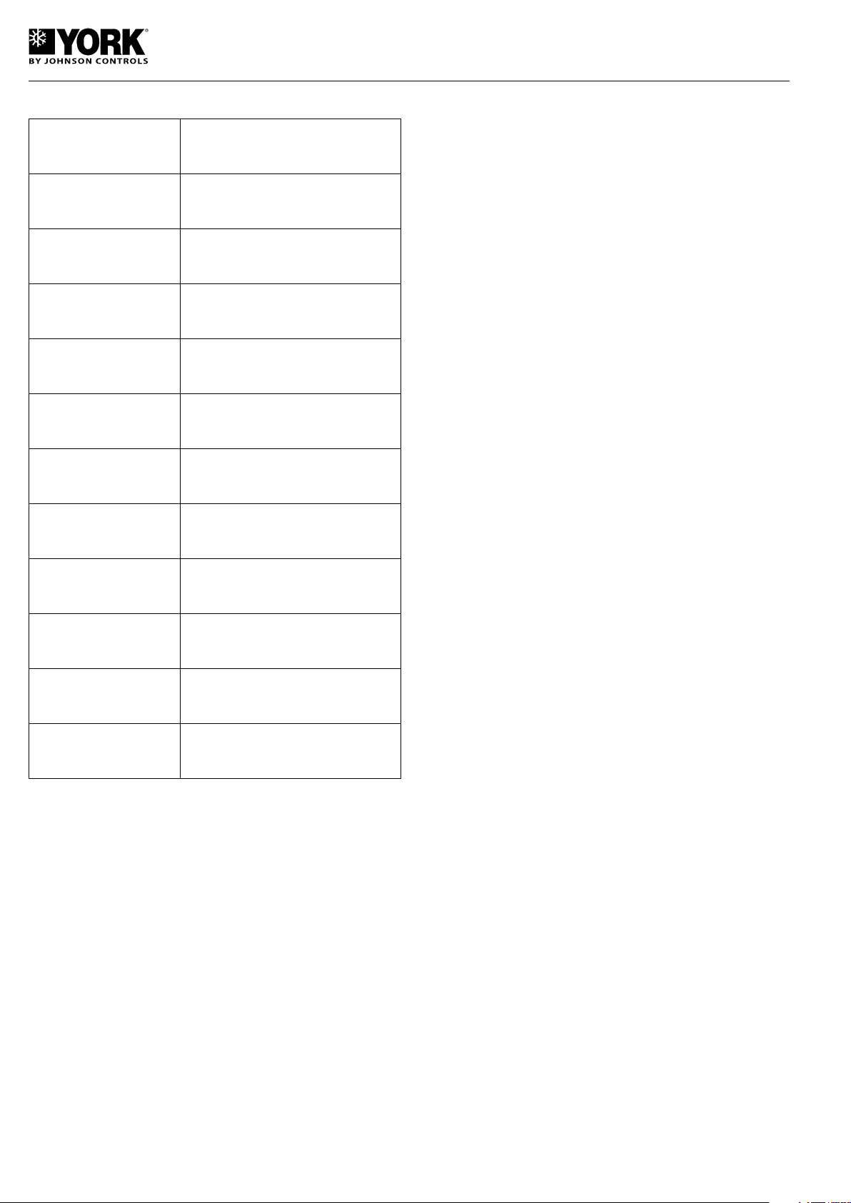
Features Advantages
compressor off cycle by simulating the buffer tank operation,
thus avoiding excessive on/off cycles of the unit. Although
this function slightly decreases water temperature control
precision, it eliminates the need to use the buffer tank.
R-410A refrigerant Does not harm the ozone layer.
Minimum dimensions Minimum footprint.
Low height and weight Space for installing on terraces.
Factory tested
equipment
Accessibility Easy maintenance.
Main switch Operator safety.
Microprocessor for
control and alarms
Manufactured to ISO 9001 High quality level.
Variable speed fan
Possibility of eliminating
the buffer tank
Communications
connection
Operating quality control.
Easy and safe operation.
Low noise level and condensation
control.
For installations with low water volume.
Ideal for building management.
Dynamic set point and suppression of buffer
tank
The YLCA/YLHA PLUS 5 to 27 control system has Dynamic
Set Point and Suppression of Buffer Tank functions.
Dynamic Set Point. Modifies water temperature control set
point in accordance with the outdoor temperature. The purpose of this is to avoid excessive an temperature differential
between the indoor and outdoor air conditioned areas. If this
differential is excessive, it could cause discomfort and thermal
shock that could be detrimental to the health of the users entering and leaving this area. On the other hand, this function,
that increases the set point in winter cycle and lowers it in
summer cycle, contributes considerably to saving energy.
Suppression of Buffer Tank. This function increases the
temperature differential that, added to the control set point,
controls the on/off cycles of the compressor when the unit is
operating at a low charge. To achieve this, the reference point
used is the duration of the compressor operating cycles. In
this way, when the water temperature falls quickly, it delays the
Technical Specifications
These units are supplied completely factory-assembled and
with all refrigerant tubing and wiring ready for installation on
the job site. After installation, these units must go through
an operational test with water. Refrigerant leaks will also be
checked during this process.
Sheeting casing
The units are made of galvanized steel sheeting and anticorrosion nuts and bolts. Panels can be removed for access to
internal components. The casing parts are painted with white
RAL9001 oven-baked polymerized enamel.
Compressor
Hermetic Scroll compressors mounted on antivibratory
supports are used. These compressors are equipped with
electronic modules that protect them against high operating
temperatures. The sump heater operates (units only 20 to
27) only when the compressor is inoperative.
Indoor heat exchanger
Comprises a stainless steel plate exchanger, adequately
insulated by a layer of closed-cell elastomer foam. The refrigerant side of said exchanger accepts an operating pressure of
52 bar, whereas the water side accepts 10 bar. When the unit
includes a hydro kit, maximum admissible pressure on the
water side is 6 bar (adjustment of the relief valve).
Outdoor heat exchanger
Made up of notched blue fin aluminium, fin coils and grooved
copper tubing mechanically expanded within the fin assembly.
Fans
Of the axial and low sound level type. Equipped with singlephase motors with IP54 protection. These motors allow speed
control by means of a phase cut-out shifter controlled by
the unit controller. This allows unit operation at low ambient
temperatures (-10°C).
An optional low ambient temperature kit (pressure sensor)
can reach -18°C. This kit is included as standard on heat
pump models YLHA PLUS. On heat pumps, the fan will remain
inoperative during defrosts.
Electric and control panel
Located inside the unit, and with IP44 protection. The operating and control components are factory mounted, wired and
tested. This control panel is equipped with a locking isolator
that turns power supply off. Inside we find the contactors for
the compressor and the pump, the transformer, magnetothermal protector, speed control, connecting strip and the
keyboard-display with the unit controls.
Control keyboard-display
This device is accessible through an external leak-tight plastic
cover. This is an easy-to-use control with three access levels:
Direct, User (password) and Factory (password). For further
information, please see Operating Instructions.
6
Page 7
Cooling circuit
11
15
30
90
24
8MA
65
11
15
160
32
130
50
10MA
45
Cool only unit: Includes Schrader valves on the high, low
and liquid sides, high and low pressure switches, filter-dryer,
expansion valve (YLCA- 5 to 15), expansion valve and liquid
sight glass (YLCA 20 to 27), and service valves for isolating
the condensing unit (pump down) (YLCA 27).
Heat pump unit: Includes Schrader valves on the high and low
sides, high and low pressure switches, filter-dryer, two expansion valves (YLHA PLUS 5 to 15), two expansion valves and
liquid sight glass (YLHA PLUS 20 to 27), service valves for
isolating the condensing unit (pump down) (YLHA PLUS 27),
liquid tank, four-way valve (energized in summer cycle) and
check valves (YLHA PLUS 20 to 27). The suction tubing is
coated with closed-cell elastomer.
Hydro kit
These units include a pack assembled with the components
of a hydro kit. This assembly is located within the unit frame
and does not increase the footprint of same. It includes the
following components: Centrifugal pump, expansion vessel
charged with nitrogen at 1.5 bar, relief valve set to 6 bar, flow
switch, air bleed valve and drain connection. Also includes
a mesh filter for the water circuit. This filter is supplied loose
for installation at the most convenient point.
Protecting grids
To protect the coils from possible impacts. Made of steel
rods and painted with oven baked polymerized white enamel
(RAL9001).
Low ambient temperature kit (YLCA 5 to 15)
Includes a pressure transducer for controlling condensing
pressure at low ambient temperature (-18°C).
Standard on models YLCA 20 & 27, and YLHA PLUS 5-27.
High pressure fans
Buffer tank
With a backup heater installed.
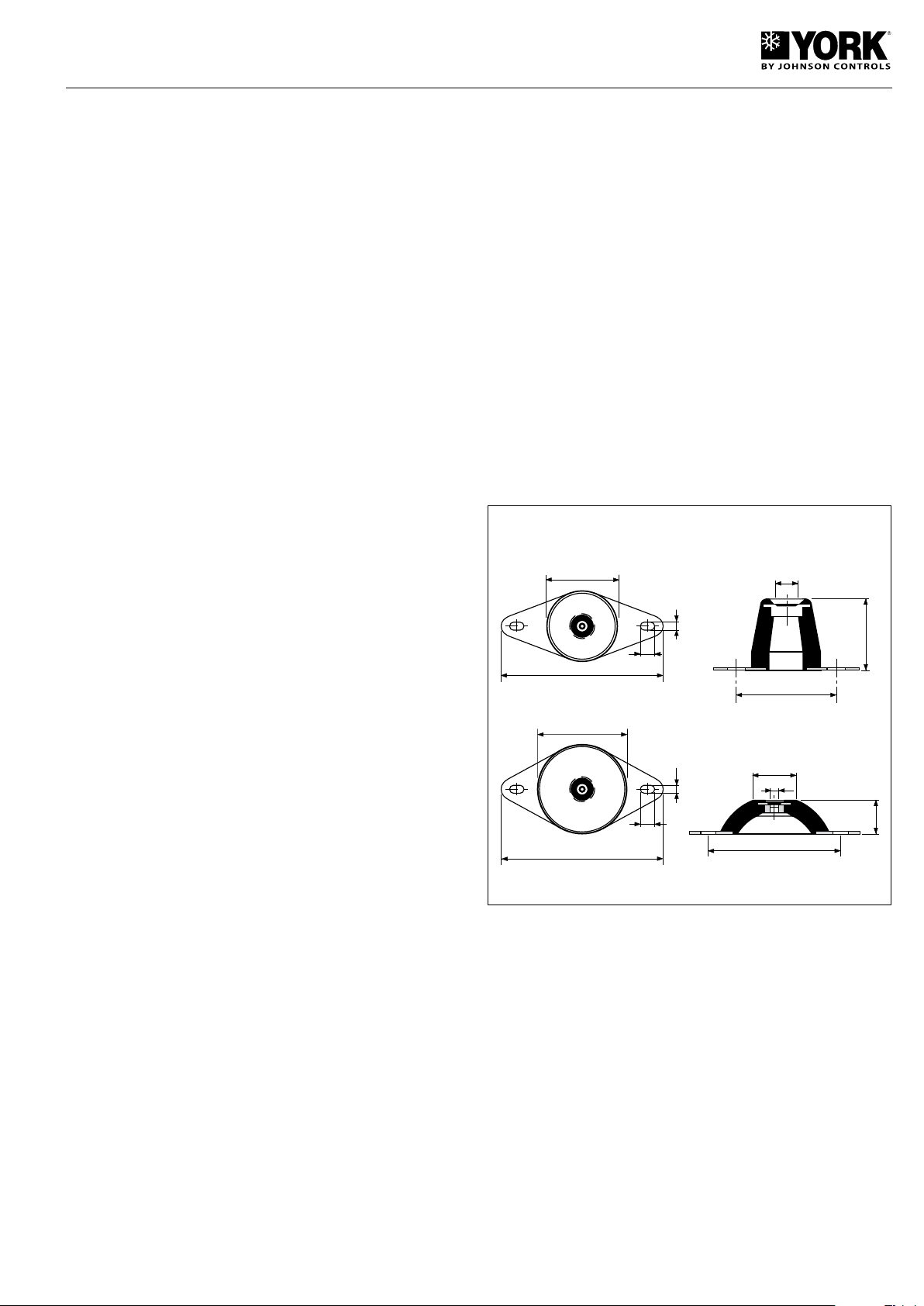
Antivibratory supports
Whenever necessary to reduce to a maximum vibrations
and noise caused by the unit, you can use a set of caoutch
antivibratory supports, that should be installed between the
supporting chassis of the unit and the base or floor on which
same should be set. This base should be solid and dimensioned in accordance with the weight to be supported. To
fasten the supports to the base of the chassis, 8/10Ma screws
are used. The antivibratory supports accessory includes 4
parts. These supports should be distributed amongst and
fastened in the drilled holes in the base, the location of which
is detailed in the General Dimensions section.
YLCA/YLHA PLUS 5 ÷ 15
Accessories and options
Remote control unit
Wall-mounted remote control unit with keyboard for cool/heat
and ON/OFF functions. Includes power supply, alarm and
cool/heat LEDs. Maximum cable length: 50 m.
Remote terminal
For total access and control of the system by means of the
display and keys. Allows selecting cool, heat and off functions.
Can also modify operating parameters and monitor the system. Can be installed at a maximum distance of 1040 m.
BMS connections
By means of a serial board, it is possible to connect the
system to a standard RS485 monitoring network.
YLCA/YLHA PLUS 20 ÷ 27
7
Page 8
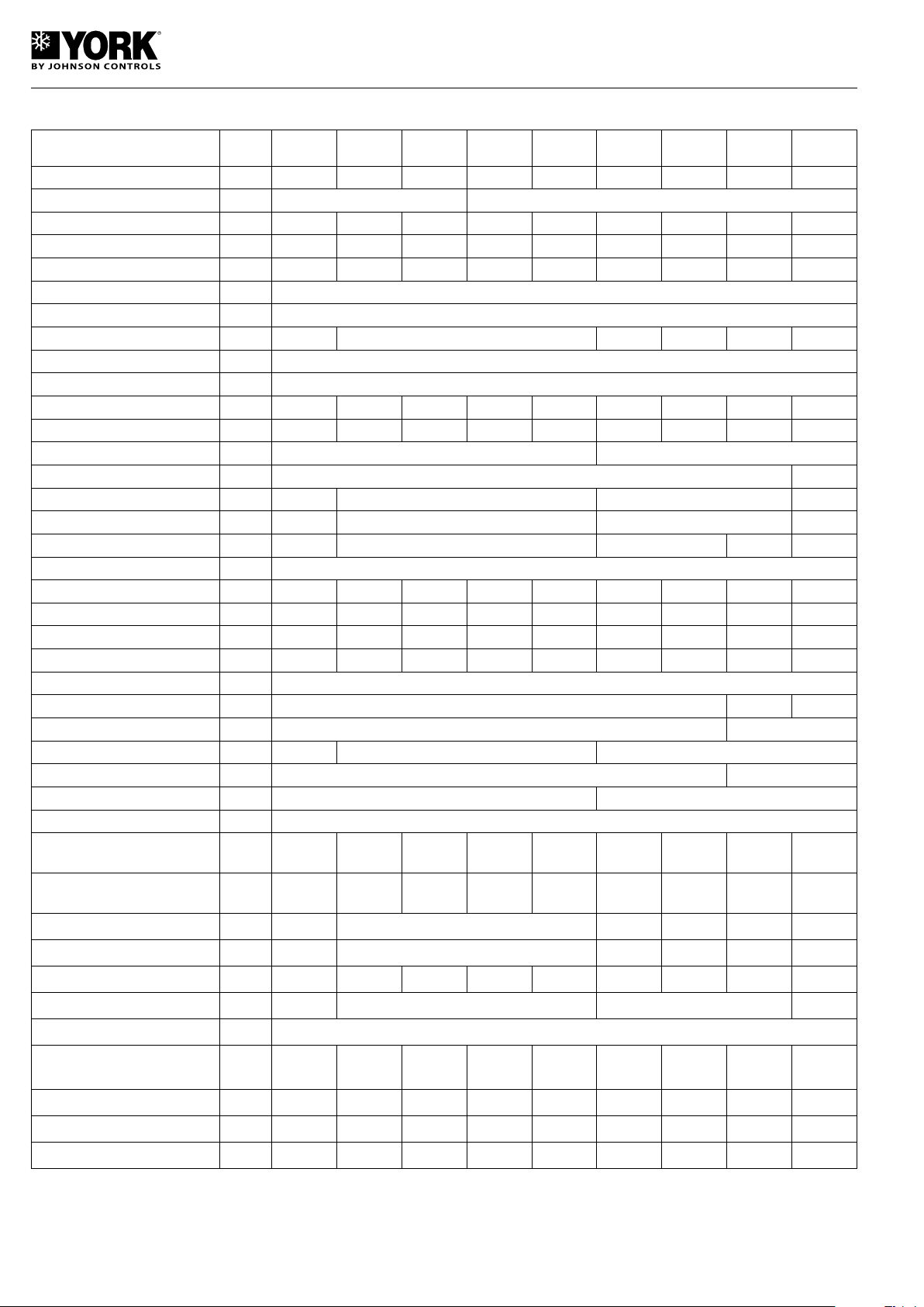
Physical data, cool only units
Characteristics
YLCA-5
M and MC
Cooling capacity kW 5.38 7.13 8.63 7.13 8.63 12.4 14.50 19.52 25.6
Power supply V/ph 230.1.50 400.3.50
Compressor consumption kW 1.73 2.41 3.40 2.41 3.16 3.80 5.38 6.57 8.73
Compressor amperage A 7.8 11.7 17 3.9 5.7 6.36 8.9 13 16.7
EER 2.87 2.76 2.41 2.76 2.59 2.97 2.52 2.81 2.81
No. of compressors 1
Compressor type SCROLL
Oil charge l 1.1 1.25 1.95 1.66 2.51 3.25
Oil type POLYOL ESTER OIL
Evaporating unit type PLACAS
Nominal water flow l/h 925 1 225 1 430 1 225 1 475 2 065 2 530 3 360 4 405
Min. water volume of inst.
(1)
l 15 20 25 20 25 35 45 55 75
No. of fans 1 2
Fan diameter mm 450 560
Fan consumption W 140 170 2 x 185 2 x 175
Fan amperage A 0.6 0.8 2 x 0.87 2 x 0.85
Total air flow m3/h 2 900 3 150 6 150 6 300 7 200
Refrigerant type R-410A
Refrigerant charge kg 2.08 2.55 2.25 2.55 2.15 3.17 3.10 5 7.8
Sound power dB (A) 70 70 71 70 71 73 73 74 78
Sound pressure at 5 m. / 5 m. dB (A) 44 44 45 44 45 47 47 48 51
Sound pressure at 10 m. /10 m. dB (A) 40 40 41 40 41 43 43 44 48
Dimensions
Length mm 905 1 430 1 876
Width mm 460 502
Height mm 762 965 1 270
Water connections. female 1" 1 1/4"
Water filter 1" 1 1/4"
No. of pumps 1
Available static pressure at nominal
flow (without filter)
Available static pressure at nominal
flow (with filter)
(2)
(3)
kPa 51 80 78 80 75 115 152 134 191
kPa 49 75.5 71 75.5 67.5 113 149 129.5 182
Pump consumption W 160 210 400 490 390 755
YLCA-7
M and MC
YLCA-9
M and MC
YLCA-7
T and TC
YLCA-9
T and TC
YLCA-12
T and TC
YLCA-15
T and TC
YLCA-20
T and TC
YLCA-27
T and TC
Pump amperage A 0.65 0.95 1.8 2.15 1.1 1.34
Unit water content l 1 1.1 1.2 1.1 1.2 1.5 2 2.8 3.2
Expansion vessel volume l 1 2 5 8
Relief valve setting Bar 6
Max. unit power supply consumption
kW 2.57 3.61 4.36 3.61 4.36 5.68 8 9.17 12.09
Max. unit current amperage A 11.75 17.1 23 7.6 8.25 11.6 15.8 18.1 23
Start-up current (compressor) A 60 82 97 35 48 51 74 95 118
(4) (5)
Weight
kg 75 99 100 99 100 146 160 220 290
(1) On installations with lower volumes, and in a low charge situation, the "suppress buffer tank" function will activate automatically. Consequently, water
temperature will lose precision in accordance with the decrease of the total water volume of the installation. Please consult before applying values lower
to those indicated. (2) Available static pressure, Eurovent certified. (3) Pressure with clean filter. (4) Weight for empty unit.
8
Page 9
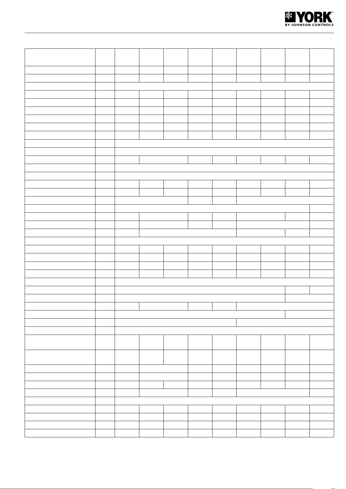
Physical data, heat pump units
Characteristics
YLHA
PLUS-5
MC
YLHA
PLUS-7
MC
YLHA
PLUS-9
MC
YLHA
PLUS-12
MC
YLHA
PLUS-9
TC
YLHA
PLUS-12
TC
YLHA
PLUS-15
TC
YLHA
PLUS-20
TC
YLHA
PLUS-27
TC
Cooling capacity kW 5.4 7.10 8.7 11.75 8.7 12 13.8 19.4 25.8
Heating capacity kW 6.3 7.16 9.52 12.25 9.52 12.4 16.1 20.9 27.5
Power supply V/ph/Hz 230.1.50 400.3.50
Comp. consumption in cooling kW 1.77 2.41 3.29 3.90 3.29 3.80 5.13 6.71 8.47
Comp. consumption in heating kW 1.76 2.30 2.98 3.55 2.98 3.77 4.81 6.06 7.89
Comp. amperage in cooling A 8.4 11.7 16.3 20.2 6 6.36 8.7 11.7 15.1
Comp. amperage in heating A 8.1 11.2 14.8 18.7 5.8 6.38 8.2 10.8 14.3
EER/COP nominal conditions 2.82/3.32 2.75/2.90 2.51/3.02 2.75/3.12 2.51/3.02 2.88/3 2.52/3.12 2.75/3.25 2.90/3.30
COP air 7/6 - water 30/35 3.78 3.48 3.88 4.01 3.88 3.86 4 3.96 4.03
No. of compressors 1
Compressor type SCROLL
Oil charge in litres l 1.1 1.25 1.24 1.25 1.24 1.89 2.51 3.25
Oil type POLYOL ESTER OIL
Evaporating unit type PLATES
Nominal flow l/h 930 1 220 1 495 2 020 1 495 1 980 2 375 3 335 4 440
Min. water volume of installation
(1)
l 15 20 25 35 25 35 45 55 75
No. of fans 1 2 1 2
Fan diameter mm 450 560
Total fan consumption W 140 170 2 x 185 170 2 x 185 2 x 180 2 x 200
Total fan amperage A 0.6 0.8 2 x 0.87 0.8 2 x 0.87 2 x 1.30
Total air flow m3/h 2 900 3 150 6 150 6 300 7 200
Refrigerant type R-410A
Refrigerant charge kg 1.86 2.55 2.35 3.14 2.35 3.50 3.40 5.80 8.20
Sound power dB (A) 70 70 71 73 71 73 73 74 78
Sound pressure at 5 m. dB (A) 44 44 45 47 45 47 47 48 51
Sound pressure at 10 m. dB (A) 40 40 41 43 41 43 43 44 48
Dimensions
Length mm 905 1 430 1 876
Width mm 460 502
Height mm 762 965 1 270 965 1 270
Water connections, female 1" 1 1/4"
Water filter, female 1" 1 1/4"
No. of pumps 1
Available static pressure at nominal flow (without filter)
Available static pressure at nominal flow (with filter)
(2)
(3)
kPa 51 80 75 116 75 118 160 130 191
kPa 49 76 67.5 100 67.5 116 157.5 124 182
Pump amperage W 160 210 400 210 400 490 390 755
Pump consumption A 0.65 0.95 1.8 0.95 1.8 2.15 1.1 1.34
Unit water content l 1 1.1 1.2 1.5 1.2 1.5 2 2.8 3.2
Expansion vessel volume l 1 2 5 2 5 8
Relief valve setting Bar 6
Max. unit power supply consumption kW 2.57 3.48 4.79 5.51 4.79 5.68 7.6 8.70 12.09
Max. unit current amperage A 11.75 16.4 23 25.7 5.5 11.6 12.4 15.5 21
Start-up current (compressor) A 60 82 97 116 48 51 74 95 118
(4)
Weight
kg 77 102 103 154 103 150 164 235 330
(1) On installations with lower volumes, and in low charge conditions, the "suppress buffer tank" function will activate automatically. Consequently, water
temperature will lose precision in accordance with the decrease of the total water volume of the installation. Please consult before applying values lower
to those indicated. (2) Available static pressure, Eurovent certified. (3) Pressure with clean filter. (4) Weight for empty unit.
9
Page 10
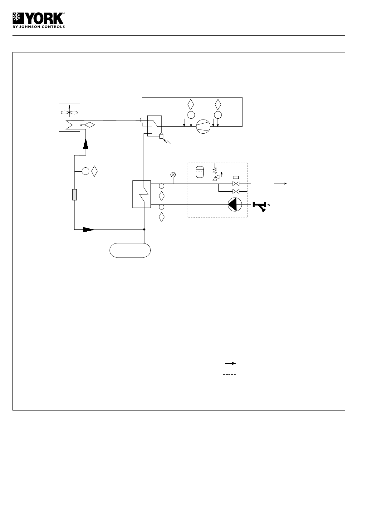
Operation, cooling and hydraulic diagram, heat pump unit YLHA PLUS 5 to 15
E
3
4
4
2
9
ON
P
1
A
B
P
10
6
14
11
8
7
13
5
12
P C
E
WATER
INTAKE
WATER
OUTLET
F
SAFETY/CONTROL DEVICES
A High pressure switch
B Low pressure switch
C Pressure transducer port
E Condensing unit temp. sensor (fan
speed setting, defrosts and display)
F Water outlet temperature sensor
(antifreeze and display)
G Water intake temperature sensor
(Setting and display)
COMPONENTS
1 Compressor
2 Air cooled condenser
3 Filter dryer
4 Expansion valve
5 Water pump
6 Plate heat exchanger
7 Automatic air bleed
8 Expansion vessel
9 Four-way valve
Cooling cycle
The 4-way valve is activated. Heat exchange takes place
between the heat transfer liquid (water or glycol water) and
the refrigerant in the plate heat exchanger. Water is cooled,
and refrigerant is evaporated and reheated. Then the Scroll
type compressor condenses the refrigerant (gas) until the condensing pressure is reached, and the refrigerant goes to the
air cooled condensing unit. In the air cooled condensing unit,
heat is exchanged between the air and the refrigerant. The air
is heated and evacuated from the chiller (heat rejection). The
10 Liquid receiver
11 Drain connection
12 Water filter (not inside the unit)
13 Relief valve
14 Flow switch
Pipe connection with Schrader valve
For units with hydro kit only
refrigerant is condensed and sub-cooled. Then the refrigerant
(liquid) goes on to the expansion valve, where it is expanded
until the evaporating pressure is reached, at which time it goes
to the evaporating unit to start a new cooling cycle.
Heating cycle
The cycle is reversed to heating mode. The 4-way valve is
not activated. The condensing unit becomes the evaporating
unit, and the evaporating unit becomes the condensing unit.
The water in the heat exchanger is heated.
10
Page 11
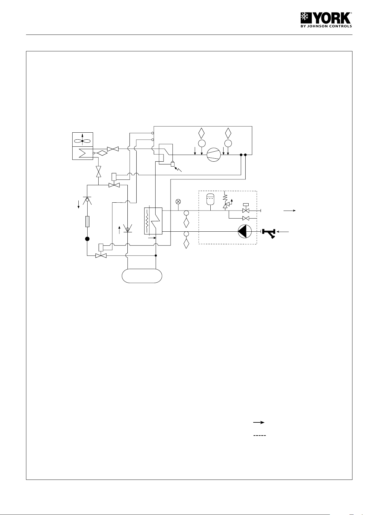
Operation, cooling and hydraulic diagram, heat pump unit YLHA PLUS 20 and 27
E
3
4
5
10
7
10
5
8
8
2
9
ON
P
1
A
B
P
11
6
16
13
12
17
WATER
OUTLET
F
14
G
WATER
INTAKE
15
18
SAFETY/CONTROL DEVICES
A High pressure switch
B Low pressure switch
E Condensing unit temperature sensors
(fan speed setting and display)
F Water outlet temperature sensor
(antifreeze, setting and display)
G Water intake temperature sensor
(setting and display)
COMPONENTS
1 Tandem compressor
2 Air cooled condenser
3 Filter dryer
4 Liquid sight glass
5 Expansion valve
6 Heat exchanger
7 Exchanger antifreeze heater
8 Globe valve (20 and 27 only)
10 Check valve
11 Liquid receiver
12 Automatic air bleed
13 Expansion vessel
14 Relief valve
15 Water pump
16 Flow switch
17 Drain connection
18 Water filter (not inside the unit)
9 4-way valve
Pipe connection with Schrader
valve
For units with hydro kit only
11
Page 12
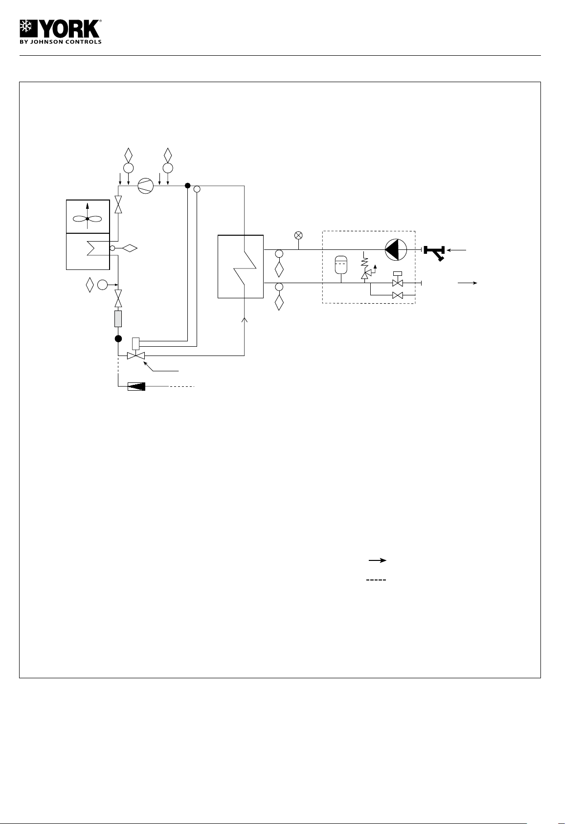
Operation, cooling and hydraulic diagram, cool only unit YLCA
D
P
A
P
B
1
8
8
P
C
5
4
6
2
3
YLCA-20. 27 (TEV)
YLCA-5 to 15 (RESTRICTOR)
7
12
11
10
F
WATER
OUTLET
WATER
INTAKE
E
14
9
13
5
SAFETY/CONTROL DEVICES
A High pressure switch
B Low pressure switch
C Pressure transducer port (LAK YLCA
5 to 15)
Pressure sensor. Pressure reading.
Fan speed setting (YLCA 20, 27)
D Coil temperature sensor. Temperature
reading and fan speed setting (YLCA
5 to 15)
E Water outlet temperature sensor
(antifreeze and display)
F Water intake temperature sensor
(Setting and display)
Heat exchange takes place between the heat transfer liquid
(water or glycol water) and the refrigerant in the plate heat
exchanger. Water is cooled, and refrigerant is evaporated
and reheated. Then the Scroll compressor condenses the
refrigerant (gas) until the condensing pressure is reached,
and the refrigerant goes to the air cooled condensing unit. In
the air cooled condensing unit, heat is exchanged between
COMPONENTS
1 Compressor
2 Air cooled condenser
3 Filter dryer
4 Sight glass (YLCA 20, 27)
5 Expansion valve
6 Plate heat exchanger
7 Flow switch
8 Globe valve (YLCA 27)
9 Water pump
10 Automatic air bleed
11 Expansion vessel
12 Drain connection
13 Water filter (not inside the unit)
14 Relief valve
Pipe connection with Schrader valve
For units with hydro kit only
the air and the refrigerant. The air is heated and evacuated
from the chiller (heat rejection).
The refrigerant is condensed and sub-cooled. Then the
refrigerant (liquid) goes on to the expansion valve, where
it is expanded until the evaporating pressure is reached,
at which time it goes to the evaporating unit to start a new
cooling cycle.
12
Page 13

Table 1. Cooling capacities YLCA 5 to 27
Outdoor ambient temperature °C DB (80% RH)
Model
YLCA
5
7
9
12
15
20
27
Water
outlet
temp.
°C
5
6
7
8
10
12
15
5
6
7
8
10
12
15
5
6
7
8
10
12
15
5
6
7
8
10
12
15
5
6
7
8
10
12
15
5
6
7
8
10
12
15
5
6
7
8
10
12
15
20 25 30 32 35 40 43 46
Cap. Unit Cap. Unit Cap. Unit Cap. Unit Cap. Unit Cap. Unit Cap. Unit Cap. Unit
kW kW kW kW kW kW kW kW kW kW kW kW kW kW kW kW
5.71 1.59 5.55 1.63 5.31 1.70 5.18 1.76 4.99 1.85 4.41 2.06 4.18 2.18 3.92 2.33
5.93 1.59 5.76 1.64 5.52 1.71 5.38 1.77 5.18 1.86 4.68 2.07 4.43 2.21 4.18 2.35
6.15 1.60 5.98 1.65 5.73 1.72 5.59 1.77 5.38 1.87 4.95 2.08 4.69 2.23 4.44 2.38
6.31 1.60 6.14 1.65 5.89 1.73 5.74 1.78 5.53 1.88 5.11 2.09 4.84 2.24 4.58 2.39
6.65 1.61 6.48 1.66 6.21 1.74 6.06 1.79 5.83 1.89 5.44 2.10 5.15 2.25 4.88 2.40
6.99 1.61 6.82 1.66 6.54 1.74 6.38 1.79 6.14 1.89 5.76 2.11 5.46 2.26 5.17 2.41
7.50 1.62 7.33 1.67 7.03 1.75 6.86 1.80 6.60 1.90 6.26 2.12 5.93 2.26 5.62 2.42
7.11 2.18 6.99 2.24 6.69 2.32 6.66 2.40 6.28 2.53 5.49 2.86 5.21 3.04 4.78 3.27
7.39 2.18 7.25 2.24 6.95 2.33 6.92 2.41 6.52 2.54 5.83 2.87 5.52 3.07 5.10 3.29
7.58 2.19 7.50 2.27 7.22 2.35 7.19 2.42 7.13 2.58 6.17 2.88 5.84 3.11 5.41 3.33
7.86 2.19 7.73 2.27 7.42 2.36 7.38 2.44 7.29 2.59 6.37 2.90 6.03 3.12 5.58 3.36
8.28 2.20 8.16 2.27 7.82 2.37 7.79 2.45 7.45 2.60 6.78 2.91 6.42 3.14 5.95 3.37
8.71 2.20 8.59 2.28 8.23 2.37 8.20 2.45 7.73 2.61 7.18 2.92 6.80 3.15 6.30 3.39
9.34 2.22 9.23 2.28 8.85 2.38 8.82 2.46 8.31 2.62 7.80 2.94 7.39 3.15 6.85 3.40
8.61 2.60 8.80 2.89 8.33 2.99 8.06 3.09 7.60 3.30 6.65 3.69 6.30 3.93 5.78 4.22
8.94 2.61 9.13 2.90 8.66 3.01 8.37 3.11 7.89 3.31 7.06 3.71 6.68 3.94 6.17 4.24
9.86 2.62 9.44 2.91 8.99 3.03 8.70 3.13 8.63 3.33 7.46 3.72 7.07 3.95 6.55 4.26
9.51 2.63 9.73 2.92 9.24 3.04 8.93 3.15 8.81 3.35 7.71 3.73 7.30 3.96 6.76 4.28
10.03 2.66 10.27 2.94 9.74 3.05 9.43 3.19 9.00 3.37 8.20 3.75 7.77 3.98 7.20 4.32
10.54 2.68 10.81 2.96 10.26 3.06 9.93 3.23 9.36 3.39 8.69 3.77 8.23 4.00 7.63 4.36
11.31 2.71 11.62 2.99 11.02 3.08 10.67 3.29 10.06 3.45 9.44 3.80 8.94 4.07 8.47 4.39
12.37 3.06 12.15 3.43 11.63 3.8 11.58 3.88 10.93 4.13 9.55 4.62 9.06 4.92 8.31 5.28
12.85 3.08 12.61 3.45 12.09 3.82 12.03 3.9 11.34 4.15 10.14 4.64 9.6 4.97 8.86 5.30
13.78 3.10 13.49 3.47 12.97 3.84 12.5 3.92 12.40 4.17 10.72 4.66 10.16 5.03 9.41 5.32
14.03 3.12 13.82 3.49 13.15 3.86 12.83 3.94 12.65 4.19 11.07 4.68 10.49 5.05 9.71 5.34
14.41 3.16 14.19 3.53 13.60 3.90 13.55 3.96 12.9 4.21 11.79 4.70 11.16 5.07 10.35 5.36
15.14 3.20 14.93 3.57 14.32 3.92 14.26 3.96 13.44 4.22 12.48 4.73 11.83 5.09 10.96 5.38
16.25 3.26 16.05 3.63 15.39 3.95 15.34 3.98 14.45 4.23 13.56 4.75 12.85 5.11 11.54 5.40
14.47 4.54 14.21 4.67 13.60 4.84 13.54 5.00 12.78 5.33 11.17 5.96 10.59 6.35 9.72 6.81
15.02 4.56 14.75 4.69 14.13 4.86 14.07 5.03 13.26 5.35 11.86 5.99 11.22 6.41 10.36 6.87
15.42 4.57 15.25 4.71 14.68 4.89 14.61 5.05 14.50 5.38 12.54 6.01 11.88 6.19 11.01 6.95
15.99 4.59 15.72 4.72 15.08 4.92 15.01 5.08 14.16 5.41 12.95 6.04 12.26 6.52 11.36 7.01
16.85 4.59 16.59 4.73 15.90 4.95 15.84 5.11 14.93 5.43 13.78 6.07 13.05 6.54 12.10 7.03
17.71 4.61 17.46 4.75 16.75 4.97 16.68 5.11 15.72 5.44 14.59 6.10 13.83 6.57 12.82 7.06
19.00 4.62 18.77 4.76 18.00 5.00 17.93 5.14 16.90 5.46 15.86 6.12 15.02 6.60 13.94 7.09
21.41 5.45 20.97 5.61 20.22 5.87 19.88 6.10 19.29 6.87 17.18 7.24 16.4 7.72 15.51 8.29
22.39 5.48 21.93 5.67 21.02 5.93 20.58 6.16 19.40 6.90 18.9 7.30 17.24 7.82 16.31 8.38
23.33 5.54 22.73 5.72 21.82 5.99 21.35 6.21 19.52 6.94 18.99 7.36 18.03 7.94 17.08 8.50
24.05 5.57 23.40 5.75 22.45 6.05 21.88 6.27 21.00 6.98 18.44 7.41 18.40 8.00 17.37 8.59
25.47 5.64 24.77 5.81 23.69 6.11 23.03 6.33 22.03 7.01 20.52 7.47 19.35 8.06 18.25 8.66
26.97 5.65 26.17 5.85 24.95 6.14 24.18 6.36 23.09 7.01 21.54 7.54 20.28 8.11 19.05 8.72
29.16 5.74 28.23 5.92 26.82 6.21 25.92 6.44 24.7 7.05 23.2 7.61 21.76 8.15 20.4 8.78
28.60 6.90 27.49 7.53 25.77 8.17 26.05 8.64 24.28 8.99 22.52 9.48 21.50 10.10 19.60 10.97
30.03 7.00 28.61 7.58 26.81 8.24 26.98 8.71 24.94 9.03 23.72 9.55 22.60 10.23 21.38 11.02
30.62 7.11 29.32 7.63 27.63 8.33 27.98 8.78 25.60 9.08 24.90 9.62 23.63 10.39 22.39 11.07
32.21 7.22 30.68 7.76 28.69 8.53 28.68 8.86 27.52 9.18 25.48 9.70 24.11 10.46 22.77 11.12
34.07 7.30 32.47 7.84 30.32 8.61 30.19 8.93 28.88 9.28 26.90 9.77 25.36 10.54 23.92 11.22
36.04 7.42 34.30 7.89 31.97 8.65 31.69 8.98 30.27 9.43 28.23 9.86 26.58 10.62 24.97 11.32
38.59 7.54 37.01 7.99 34.42 8.74 33.98 9.08 32.38 9.58 30.41 9.96 28.53 10.66 26.96 11.47
13
Page 14

Table 2. Cooling capacities YLCA 5 to 27 (35% ethylene glycol)
Outdoor ambient temperature °C DB (80% RH)
Model
YLCA
5
7
9
12
15
20
27
Water
outlet
temp.
°C
-5
-4
-2
0
2
4
-5
-4
-2
0
2
4
-5
-4
-2
0
2
4
-5
-4
-2
0
2
4
-5
-4
-2
0
2
4
-5
-4
-2
0
2
4
-5
-4
-2
0
2
4
20 25 30 32 35 40 43 46
Cap. Unit Cap. Unit Cap. Unit Cap. Unit Cap. Unit Cap. Unit Cap. Unit Cap. Unit
kW kW kW kW kW kW kW kW kW kW kW kW kW kW kW kW
3.60 1.12 3.44 1.22 3.28 1.32 3.20 1.37 3.08 1.44 2.83 1.57 2.68 1.65 2.53 1.74
3.79 1.15 3.63 1.24 3.44 1.35 3.36 1.40 3.23 1.47 2.97 1.61 2.81 1.69 2.64 1.80
4.14 1.21 3.99 1.30 3.77 1.42 3.68 1.46 3.55 1.54 3.25 1.68 3.08 1.77 2.88 1.87
4.49 1.26 4.36 1.36 4.14 1.48 4.03 1.53 3.88 1.61 3.56 1.76 3.36 1.85 3.12 1.94
4.98 1.32 4.75 1.42 4.51 1.55 4.40 1.60 4.24 1.68 3.89 1.84 3.67 1.93 3.47 2.02
5.33 1.37 5.14 1.48 4.88 1.61 4.77 1.67 4.59 1.75 4.21 1.92 3.99 2.01 3.77 2.13
4.49 1.53 4.34 1.66 4.13 1.81 4.12 1.87 3.88 1.96 3.52 2.18 3.34 2.30 3.08 2.44
4.73 1.57 4.57 1.70 4.33 1.85 4.31 1.91 4.07 2.01 3.69 2.23 3.50 2.36 3.21 2.52
5.16 1.65 5.02 1.78 4.75 1.94 4.73 2.00 4.47 2.10 4.05 2.33 3.83 2.47 3.51 2.62
5.60 1.72 5.49 1.86 5.22 2.02 5.18 2.09 4.88 2.20 4.43 2.44 4.19 2.58 3.80 2.73
6.20 1.80 5.98 1.94 5.68 2.11 5.65 2.18 5.33 2.30 4.84 2.55 4.58 2.69 4.23 2.83
6.64 1.88 6.47 2.03 6.14 2.20 6.13 2.28 5.78 2.40 5.25 2.66 4.97 2.81 4.59 2.99
5.78 2.00 5.52 2.17 5.26 2.36 5.14 2.43 4.95 2.56 4.54 2.80 4.29 2.94 4.06 3.10
6.08 2.05 5.82 2.22 5.51 2.41 5.38 2.49 5.19 2.62 4.76 2.87 4.50 3.01 4.23 3.20
6.65 2.15 6.39 2.32 6.05 2.52 5.91 2.61 5.69 2.74 5.22 2.99 4.94 3.15 4.62 3.33
7.21 2.25 6.99 2.42 6.65 2.64 6.46 2.73 6.22 2.87 5.71 3.13 5.40 3.30 5.01 3.46
7.98 2.35 7.62 2.53 7.24 2.75 7.05 2.85 6.79 2.99 6.23 3.27 5.89 3.44 5.57 3.60
8.54 2.45 8.24 2.64 7.83 2.87 7.65 2.97 7.37 3.12 6.76 3.41 6.39 3.59 6.04 3.80
8.31 2.50 7.94 2.71 7.56 2.95 7.38 3.05 7.11 3.21 6.52 3.50 6.17 3.68 5.83 3.88
8.74 2.56 8.36 2.78 7.92 3.02 7.74 3.12 7.45 3.28 6.83 3.59 6.47 3.77 6.08 4.00
9.55 2.69 9.19 2.90 8.69 3.16 8.49 3.27 8.18 3.43 7.50 3.75 7.09 3.95 6.63 4.17
10.35 2.81 10.05 3.03 9.55 3.30 9.28 3.41 8.94 3.59 8.20 3.92 7.75 4.13 7.19 4.34
11.47 2.94 10.94 3.17 10.40 3.45 10.13 3.56 9.76 3.75 8.96 4.10 8.47 4.31 8.00 4.50
12.28 3.06 11.84 3.31 11.25 3.60 10.99 3.71 10.59 3.91 9.71 4.28 9.19 4.49 8.68 4.75
9.72 3.23 9.28 3.50 8.84 3.81 8.63 3.93 8.31 4.14 7.63 4.52 7.22 4.75 6.82 5.00
10.22 3.31 9.77 3.58 9.26 3.90 9.05 4.02 8.71 4.23 7.99 4.63 7.56 4.86 7.11 5.16
11.17 3.47 10.74 3.74 10.16 4.08 9.92 4.21 9.56 4.43 8.77 4.84 8.29 5.09 7.76 5.38
12.11 3.63 11.75 3.92 11.17 4.26 10.85 4.40 10.45 4.63 9.59 5.06 9.06 5.33 8.41 5.60
13.41 3.79 12.80 4.09 12.16 4.45 11.85 4.60 11.42 4.84 10.47 5.29 9.90 5.56 9.35 5.81
14.36 3.95 13.85 4.27 13.15 4.64 12.85 4.79 12.38 5.05 11.36 5.52 10.74 5.80 10.15 6.13
13.61 3.86 13.05 4.20 12.48 4.60 12.25 4.77 11.74 5.34 10.94 5.54 10.42 5.85 9.87 6.21
14.39 3.98 13.78 4.31 13.08 4.73 12.82 4.89 11.87 5.46 11.38 5.69 10.79 6.01 10.14 6.42
15.79 4.19 15.19 4.53 14.37 4.97 14.03 5.15 13.47 5.72 12.38 5.97 11.70 6.31 10.92 6.71
17.2 4.41 16.66 4.76 15.81 5.21 15.3 5.40 14.65 5.97 13.42 6.26 12.64 6.62 11.67 7.00
19.2 4.62 18.22 5.01 17.21 5.47 16.66 5.67 15.93 6.24 14.53 6.57 13.65 6.94 12.79 7.29
20.71 4.86 19.79 5.26 18.62 5.74 18.02 5.95 17.2 6.51 15.62 6.89 14.63 7.26 13.67 7.72
17.84 5.05 17.10 5.50 16.36 6.01 16.06 6.24 15.56 6.98 14.34 7.25 13.66 7.66 12.93 8.12
18.86 5.20 18.07 5.64 17.15 6.18 16.80 6.40 16.61 7.14 14.91 7.45 14.14 7.87 13.30 8.40
20.70 5.49 19.92 5.93 18.83 6.50 18.40 6.73 17.66 7.48 16.23 7.81 15.33 8.26 14.31 8.78
22.55 5.77 21.84 6.23 20.72 6.81 20.06 7.07 19.21 7.81 17.60 8.20 16.56 8.66 15.29 9.16
25.17 6.05 23.88 6.55 22.56 7.16 21.84 7.42 20.88 8.16 19.05 8.60 17.89 9.08 16.76 9.54
27.14 6.36 25.94 6.89 24.41 7.51 23.62 7.78 22.54 8.52 20.47 9.01 19.18 9.50 17.92 10.10
14
Page 15
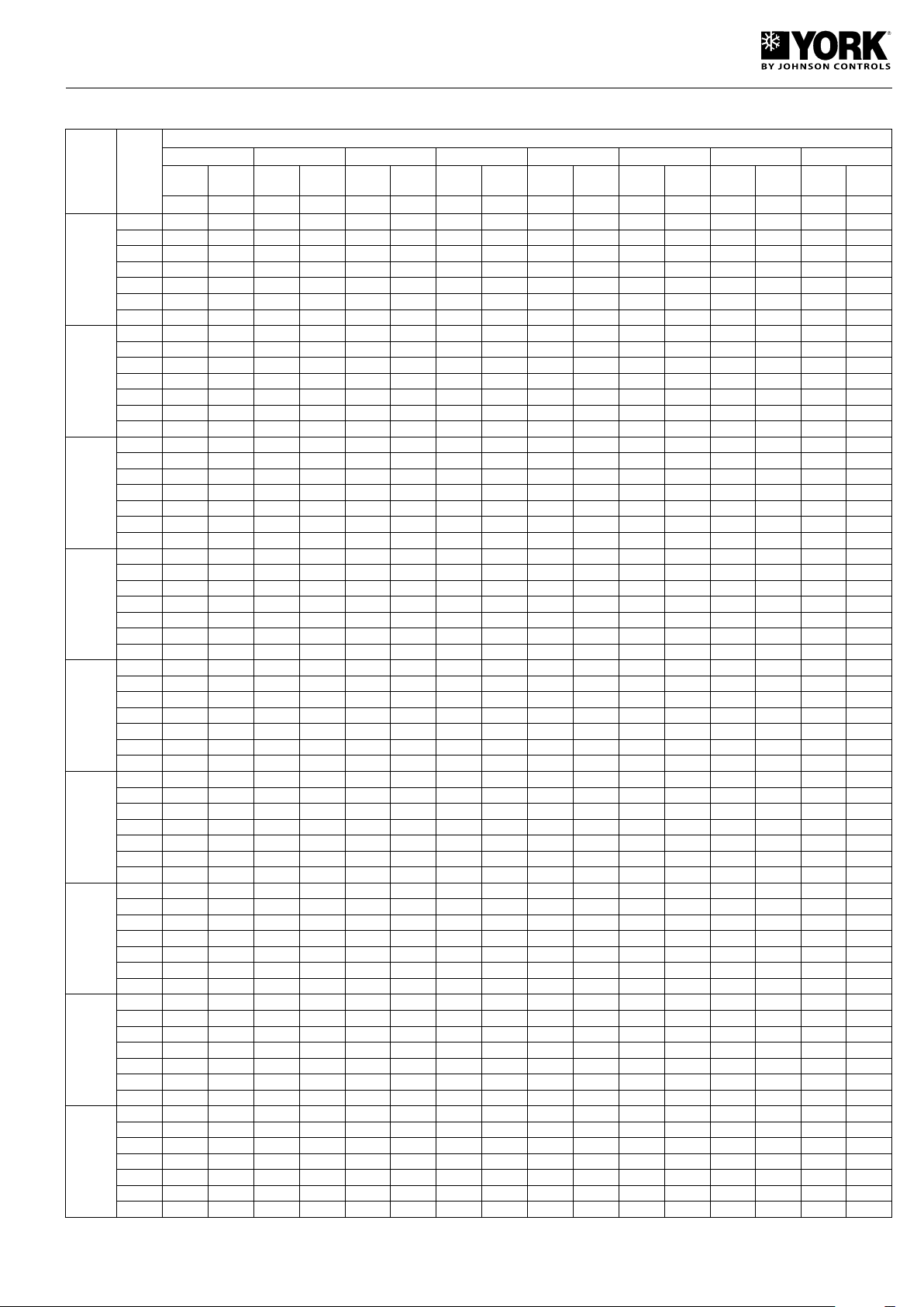
Table 3. Cooling capacities YLHA PLUS 5 to 27
Outdoor ambient temperature °C DB (80% RH)
Cap.
Abs.
power
Cap.
Model
YLHA
PLUS
5 M
7 M
9 M
9 T
12 M
12 T
15 T
20 T
27 T
Water
outlet
temp.
°C
5
6
7
8
10
12
15
5
6
7
8
10
12
15
5
6
7
8
10
12
15
5
6
7
8
10
12
15
5
6
7
8
10
12
15
5
6
7
8
10
12
15
5
6
7
8
10
12
15
5
6
7
8
10
12
15
5
6
7
8
10
12
15
20 25 30 32 35 40 43 46
Abs.
Cap.
power
kW kW kW kW kW kW kW kW kW kW kW kW kW kW kW kW
6.00 1.50 5.70 1.58 5.25 1.70 5.10 1.80 5.06 1.90 4.49 2.10 4.22 2.23 3.88 2.50
6.25 1.50 5.80 1.59 5.45 1.71 5.29 1.81 5.23 1.90 4.77 2.11 4.47 2.23 4.07 2.50
6.50 1.51 5.90 1.60 5.60 1.72 5.48 1.81 5.40 1.91 5.06 2.12 4.72 2.24 4.22 2.51
6.60 1.51 6.00 1.61 5.67 1.73 5.59 1.82 5.55 1.92 5.21 2.13 4.87 2.26 4.41 2.51
6.70 1.51 6.20 1.61 5.86 1.75 5.70 1.84 5.70 1.95 5.36 2.16 5.10 2.29 4.64 2.52
6.80 1.52 6.40 1.62 6.01 1.76 5.86 1.85 5.82 1.97 5.51 2.19 5.32 2.32 4.98 2.52
7.00 1.52 6.70 1.63 6.24 1.78 6.08 1.87 5.97 2.00 5.70 2.22 5.59 2.37 5.30 2.53
7.60 2.06 7.30 2.14 6.90 2.30 6.70 2.43 6.65 2.56 5.90 2.84 5.55 3.01 5.10 3.20
7.75 2.07 7.45 2.15 7.10 2.31 6.95 2.44 6.88 2.57 6.28 2.85 5.88 3.02 5.35 3.24
7.90 2.07 7.60 2.16 7.30 2.32 7.20 2.45 7.10 2.58 6.65 2.86 6.20 3.03 5.55 3.28
8.05 2.08 7.75 2.17 7.45 2.34 7.35 2.46 7.30 2.60 6.85 2.88 6.40 3.05 5.80 3.32
8.30 2.08 7.90 2.18 7.70 2.36 7.50 2.48 7.50 2.63 7.05 2.92 6.70 3.09 6.10 3.38
8.55 2.09 8.20 2.19 7.90 2.38 7.70 2.50 7.65 2.66 7.25 2.96 7.00 3.14 6.55 3.42
8.90 2.09 8.50 2.20 8.20 2.40 8.00 2.53 7.85 2.70 7.50 3.00 7.35 3.20 6.97 3.48
9.31 2.76 8.95 2.87 8.45 3.08 8.21 3.26 8.15 3.43 7.23 3.81 6.80 4.04 6.25 4.29
9.50 2.78 9.13 2.88 8.70 3.10 8.52 3.27 8.42 3.45 7.69 3.82 7.20 4.04 6.56 4.35
9.68 2.78 9.31 2.90 8.95 3.11 8.82 3.29 8.70 3.46 8.15 3.84 7.60 4.06 6.80 4.40
9.86 2.79 9.50 2.91 9.13 3.14 9.01 3.30 8.95 3.49 8.39 3.86 7.84 4.09 7.11 4.45
10.17 2.79 9.68 2.92 9.44 3.16 9.19 3.33 9.19 3.53 8.64 3.92 8.21 4.14 7.47 4.53
10.48 2.80 10.05 2.94 9.68 3.19 9.44 3.35 9.37 3.57 8.88 3.97 8.58 4.21 8.03 4.59
10.91 2.80 10.42 2.95 10.05 3.22 9.80 3.39 9.62 3.62 9.19 4.02 9.01 4.29 8.54 4.67
9.31 2.76 8.95 2.87 8.45 3.08 8.21 3.26 8.15 3.43 7.23 3.81 6.80 4.04 6.25 4.29
9.50 2.78 9.13 2.88 8.70 3.10 8.52 3.27 8.42 3.45 7.69 3.82 7.20 4.04 6.56 4.35
9.68 2.78 9.31 2.90 8.95 3.11 8.82 3.29 8.70 3.46 8.15 3.84 7.60 4.06 6.80 4.40
9.86 2.79 9.50 2.91 9.13 3.14 9.01 3.30 8.95 3.49 8.39 3.86 7.84 4.09 7.11 4.45
10.17 2.79 9.68 2.92 9.44 3.16 9.19 3.33 9.19 3.53 8.64 3.92 8.21 4.14 7.47 4.53
10.48 2.80 10.05 2.94 9.68 3.19 9.44 3.35 9.37 3.57 8.88 3.97 8.58 4.21 8.03 4.59
10.91 2.80 10.42 2.95 10.05 3.22 9.80 3.39 9.62 3.62 9.19 4.02 9.01 4.29 8.54 4.67
12.63 3.36 12.08 3.48 11.60 3.81 11.09 4.02 11.01 4.24 9.76 4.70 9.18 4.98 8.60 5.28
12.90 3.37 12.33 3.50 11.90 3.82 11.50 4.04 11.38 4.25 10.38 4.71 9.72 4.99 8.85 5.32
13.40 3.39 12.99 3.52 12.43 3.84 11.92 4.05 11.75 4.27 11.01 4.73 10.26 5.01 9.18 5.34
13.55 3.44 12.83 3.59 12.55 3.87 12.16 4.07 12.08 4.30 11.34 4.77 10.59 5.05 9.60 5.36
13.74 3.44 13.07 3.61 12.74 3.91 12.41 4.10 12.41 4.35 11.67 4.83 11.09 5.11 10.10 5.40
14.15 3.46 13.57 3.62 13.07 3.94 12.74 4.14 12.66 4.40 12.00 4.90 11.58 5.20 10.84 5.44
14.73 3.46 14.07 3.64 13.57 3.97 13.24 4.19 12.99 4.47 12.41 4.97 12.16 5.30 11.53 5.52
12.9 3.27 12.34 3.39 11.85 3.71 11.32 3.92 11.24 4.13 9.97 4.58 9.38 4.85 8.78 5.14
13.17 3.28 12.59 3.41 12.15 3.72 11.75 3.93 11.62 4.14 10.61 4.59 9.93 4.86 9.04 5.18
13.69 3.30 13.27 3.43 12.69 3.74 12.17 3.95 12.00 4.16 11.24 4.61 10.48 4.89 9.38 5.20
13.84 3.35 13.10 3.50 12.82 3.77 12.42 3.97 12.34 4.19 11.58 4.64 10.82 4.92 9.80 5.22
14.03 3.35 13.35 3.52 13.01 3.81 12.68 4.00 12.68 4.24 11.92 4.71 11.32 4.98 10.31 5.26
14.45 3.37 13.86 3.53 13.35 3.84 13.01 4.03 12.93 4.29 12.25 4.77 11.83 5.06 11.07 5.30
15.04 3.37 14.37 3.55 13.86 3.87 13.52 4.08 13.27 4.35 12.68 4.84 12.42 5.16 11.78 5.38
14.83 4.30 14.19 4.46 13.62 4.88 13.02 5.15 12.93 5.43 11.47 6.02 10.79 6.38 10.10 6.76
15.15 4.32 14.48 4.48 13.98 4.90 13.51 5.17 13.36 5.45 12.20 6.03 11.42 6.39 10.40 6.82
15.74 4.34 15.26 4.51 14.60 4.92 13.99 5.19 13.80 5.47 12.93 6.06 12.05 6.42 10.79 6.84
15.91 4.41 15.06 4.60 14.74 4.96 14.29 5.22 14.19 5.51 13.31 6.11 12.44 6.47 11.27 6.87
16.13 4.41 15.35 4.62 14.97 5.00 14.58 5.26 14.58 5.58 13.70 6.19 13.02 6.55 11.86 6.92
16.62 4.43 15.94 4.64 15.35 5.05 14.97 5.30 14.87 5.64 14.09 6.28 13.61 6.66 12.73 6.97
17.30 4.43 16.52 4.66 15.94 5.09 15.55 5.36 15.26 5.72 14.58 6.36 14.29 6.78 13.55 7.07
21.00 5.36 20.83 5.69 20.09 5.96 19.74 6.19 19.16 6.67 17.06 7.35 16.29 7.83 14.21 8.35
22.24 5.39 21.68 5.75 20.88 6.02 20.45 6.25 19.80 7.00 17.97 7.40 17.12 7.93 16.20 8.40
23.17 5.43 22.58 5.80 21.67 6.08 21.21 6.30 19.40 7.04 18.87 7.46 17.91 8.05 16.97 8.45
23.89 5.46 23.25 5.83 22.30 6.14 21.73 6.36 20.86 7.08 19.31 7.52 18.27 8.11 17.26 8.50
25.30 5.54 24.60 5.89 23.53 6.20 22.88 6.42 21.88 7.11 20.38 7.58 19.22 8.17 18.12 8.55
26.79 5.60 25.99 5.93 24.79 6.23 24.02 6.46 22.94 7.11 21.39 7.64 20.14 8.23 18.92 8.60
29.24 5.69 28.04 6.01 26.64 6.30 25.75 6.53 24.54 7.15 23.05 7.72 21.62 8.27 20.30 8.70
28.29 6.97 27.71 7.17 26.71 7.51 26.26 7.80 25.49 8.78 22.69 9.26 21.67 9.87 20.49 10.60
29.58 7.01 28.84 7.25 27.77 7.58 27.19 7.87 26.33 8.82 23.90 9.33 22.77 10.00 21.55 10.71
30.82 7.09 30.03 7.31 28.82 7.66 28.20 7.94 25.80 8.87 25.09 9.40 23.82 10.14 22.57 10.86
31.77 7.12 30.92 7.34 29.66 7.73 28.90 8.01 27.74 8.92 25.68 9.47 24.30 10.22 22.95 10.98
33.64 7.20 32.72 7.43 31.30 7.81 30.43 8.09 29.10 8.96 27.11 9.55 25.56 10.30 24.10 11.06
35.63 7.23 34.57 7.47 32.96 7.85 31.94 8.13 30.50 8.96 28.45 9.63 26.79 10.37 25.16 11.14
38.52 7.33 37.30 7.57 35.43 7.94 34.25 8.23 32.63 9.01 30.65 9.73 28.75 10.41 26.95 11.22
Cap.
Abs.
power
Abs.
power
Cap.
Abs.
power
Cap.
Abs.
power
Cap.
Abs.
power
Cap.
Abs.
power
15
Page 16

Table 4. Cooling capacities YLHA PLUS 5 to 27 (35% ethylene glycol)
Outdoor ambient temperature °C DB (80% RH)
Cap.
Abs.
power
Cap.
Abs.
power
Cap.
Abs.
power
Cap.
Model
YLHA
PLUS
5 M
7 M
9 M
9 T
12 M
12 T
15 T
20 T
27 T
Water
outlet
temp.
°C
-5
-4
-2
0
2
4
-5
-4
-2
0
2
4
-5
-4
-2
0
2
4
-5
-4
-2
0
2
4
-5
-4
-2
0
2
4
-5
-4
-2
0
2
4
-5
-4
-2
0
2
4
-5
-4
-2
0
2
4
-5
-4
-2
0
2
4
20 25 30 32 35 40 43 46
Abs.
Cap.
power
kW kW kW kW kW kW kW kW kW kW kW kW kW kW kW kW
3.62 1.15 3.46 1.24 3.29 1.35 3.21 1.40 3.10 1.47 2.84 1.61 2.69 1.69 2.54 1.78
3.81 1.17 3.64 1.27 3.45 1.38 3.37 1.43 3.25 1.50 2.98 1.64 2.82 1.73 2.65 1.83
4.16 1.23 4.00 1.33 3.78 1.45 3.70 1.50 3.56 1.57 3.27 1.72 3.09 1.81 2.89 1.91
4.51 1.29 4.38 1.39 4.16 1.51 4.04 1.56 3.89 1.64 3.57 1.80 3.38 1.89 3.13 1.99
5.00 1.35 4.77 1.45 4.53 1.58 4.41 1.63 4.25 1.72 3.90 1.88 3.69 1.97 3.48 2.06
5.35 1.40 5.16 1.52 4.90 1.65 4.79 1.70 4.61 1.79 4.23 1.96 4.00 2.06 3.78 2.18
4.76 1.55 4.54 1.68 4.33 1.83 4.23 1.89 4.07 1.98 3.73 2.17 3.53 2.28 3.34 2.40
5.01 1.59 4.79 1.72 4.53 1.87 4.43 1.93 4.27 2.03 3.91 2.22 3.70 2.33 3.48 2.48
5.47 1.66 5.26 1.80 4.97 1.96 4.86 2.02 4.68 2.12 4.30 2.32 4.06 2.44 3.80 2.58
5.93 1.74 5.75 1.88 5.47 2.04 5.31 2.11 5.12 2.22 4.70 2.43 4.44 2.55 4.12 2.68
6.57 1.82 6.27 1.96 5.95 2.13 5.80 2.20 5.59 2.32 5.13 2.54 4.85 2.67 4.58 2.79
7.03 1.90 6.78 2.05 6.44 2.22 6.29 2.30 6.06 2.42 5.56 2.65 5.26 2.78 4.97 2.94
5.83 2.08 5.57 2.25 5.30 2.45 5.18 2.53 4.99 2.66 4.58 2.91 4.33 3.06 4.09 3.22
6.13 2.13 5.86 2.30 5.56 2.51 5.43 2.59 5.23 2.72 4.79 2.98 4.54 3.13 4.26 3.32
6.70 2.23 6.45 2.41 6.09 2.62 5.95 2.71 5.74 2.85 5.26 3.11 4.98 3.27 4.65 3.46
7.26 2.34 7.05 2.52 6.70 2.74 6.51 2.83 6.27 2.98 5.76 3.26 5.44 3.43 5.05 3.60
8.05 2.44 7.68 2.63 7.30 2.86 7.11 2.96 6.85 3.11 6.28 3.40 5.94 3.58 5.61 3.74
8.61 2.54 8.31 2.74 7.89 2.98 7.71 3.08 7.43 3.24 6.81 3.55 6.45 3.73 6.09 3.94
5.83 2.08 5.57 2.25 5.30 2.45 5.18 2.53 4.99 2.66 4.58 2.91 4.33 3.06 4.09 3.22
6.13 2.13 5.86 2.30 5.56 2.51 5.43 2.59 5.23 2.72 4.79 2.98 4.54 3.13 4.26 3.32
6.70 2.23 6.45 2.41 6.09 2.62 5.95 2.71 5.74 2.85 5.26 3.11 4.98 3.27 4.65 3.46
7.26 2.34 7.05 2.52 6.70 2.74 6.51 2.83 6.27 2.98 5.76 3.26 5.44 3.43 5.05 3.60
8.05 2.44 7.68 2.63 7.30 2.86 7.11 2.96 6.85 3.11 6.28 3.40 5.94 3.58 5.61 3.74
8.61 2.54 8.31 2.74 7.89 2.98 7.71 3.08 7.43 3.24 6.81 3.55 6.45 3.73 6.09 3.94
7.87 2.56 7.52 2.78 7.16 3.02 6.99 3.12 6.74 3.28 6.18 3.59 5.85 3.77 5.52 3.97
8.28 2.63 7.92 2.84 7.50 3.09 7.33 3.19 7.06 3.36 6.48 3.67 6.13 3.86 5.76 4.10
9.05 2.75 8.71 2.97 8.23 3.24 8.04 3.34 7.75 3.52 7.11 3.84 6.72 4.04 6.29 4.27
9.81 2.88 9.52 3.11 9.05 3.38 8.79 3.49 8.47 3.67 7.77 4.02 7.35 4.23 6.82 4.44
10.87 3.01 10.37 3.25 9.85 3.53 9.60 3.65 9.25 3.84 8.49 4.20 8.03 4.41 7.58 4.61
11.63 3.14 11.22 3.39 10.66 3.68 10.41 3.80 10.03 4.00 9.20 4.38 8.71 4.60 8.23 4.87
8.04 2.50 7.68 2.71 7.31 2.94 7.14 3.04 6.88 3.20 6.31 3.50 5.97 3.67 5.64 3.87
8.46 2.56 8.09 2.77 7.66 3.01 7.49 3.11 7.21 3.27 6.61 3.58 6.26 3.76 5.88 3.99
9.24 2.68 8.89 2.89 8.41 3.15 8.21 3.26 7.91 3.43 7.26 3.74 6.86 3.94 6.42 4.16
10.02 2.81 9.72 3.03 9.24 3.29 8.98 3.40 8.65 3.58 7.94 3.92 7.50 4.12 6.96 4.33
11.10 2.93 10.59 3.16 10.06 3.44 9.81 3.56 9.45 3.74 8.67 4.09 8.20 4.30 7.74 4.49
11.88 3.06 11.46 3.30 10.89 3.59 10.64 3.71 10.25 3.90 9.40 4.26 8.89 4.48 8.40 4.74
9.25 3.28 8.83 3.56 8.41 3.87 8.21 4.00 7.91 4.21 7.26 4.60 6.87 4.83 6.49 5.09
9.73 3.36 9.30 3.64 8.81 3.96 8.61 4.09 8.29 4.30 7.61 4.71 7.20 4.95 6.76 5.25
10.63 3.53 10.22 3.81 9.67 4.15 9.44 4.28 9.10 4.50 8.35 4.92 7.89 5.18 7.38 5.47
11.52 3.69 11.18 3.98 10.63 4.33 10.33 4.48 9.95 4.71 9.13 5.15 8.63 5.41 8.00 5.69
12.77 3.86 12.18 4.16 11.57 4.52 11.28 4.67 10.87 4.92 9.97 5.38 9.43 5.65 8.90 5.91
13.66 4.02 13.18 4.34 12.52 4.72 12.23 4.87 11.78 5.13 10.81 5.61 10.22 5.89 9.66 6.24
13.00 4.22 12.42 4.58 11.82 4.98 11.55 5.15 11.12 5.41 10.20 5.92 9.65 6.22 9.12 6.55
13.68 4.33 13.08 4.69 12.39 5.10 12.10 5.27 11.66 5.54 10.69 6.06 10.12 6.37 9.51 6.76
14.94 4.54 14.37 4.90 13.59 5.34 13.28 5.51 12.79 5.80 11.74 6.33 11.10 6.66 10.38 7.04
16.20 4.75 15.72 5.12 14.94 5.57 14.52 5.76 13.98 6.06 12.83 6.63 12.13 6.97 11.25 7.32
17.95 4.96 17.12 5.35 16.27 5.82 15.86 6.02 15.27 6.33 14.01 6.92 13.25 7.28 12.51 7.60
19.21 5.17 18.53 5.58 17.60 6.07 17.19 6.27 16.57 6.60 15.20 7.22 14.37 7.58 13.58 8.03
17.29 5.32 16.51 5.77 15.72 6.28 15.36 6.48 14.79 6.82 13.57 7.45 12.84 7.83 12.13 8.25
18.19 5.46 17.39 5.90 16.48 6.43 16.09 6.63 15.50 6.98 14.22 7.63 13.46 8.02 12.64 8.52
19.87 5.72 19.12 6.17 18.07 6.72 17.66 6.95 17.01 7.30 15.61 7.98 14.76 8.39 13.80 8.87
21.54 5.99 20.90 6.45 19.87 7.02 19.31 7.26 18.59 7.63 17.07 8.35 16.13 8.78 14.96 9.22
23.87 6.25 22.77 6.75 21.64 7.33 21.09 7.58 20.31 7.98 18.64 8.72 17.62 9.17 16.64 9.58
25.54 6.52 24.64 7.04 23.40 7.65 22.87 7.90 22.03 8.32 20.21 9.09 19.12 9.56 18.06 10.11
Cap.
Abs.
power
Abs.
power
Cap.
Abs.
power
Cap.
Abs.
power
16
Page 17

Table 5. Heating capacities YLHA PLUS 5 to 27
Model
YLHA
PLUS
5 M
7 M
9 M
9 T
12 M
12 T
15 T
20 T
27 T
Water
outlet
temp.
°C
30
35
40
45
50 - -
30
35
40
45 - -
50 - -
30
35
40
45
50
30
35
40
45
50
30
35
40
45
50
30
35
40
45
50
30
35
40
45
50
30
35
40
45
50
30
35
40
45
50
-15 -10 -7 0 5 7 10 15 20
Abs.
Cap.
power
kW kW kW kW kW kW kW kW kW kW kW kW kW kW kW kW kW kW
1.60 1.40 1.69 1.41 2.48 1.42 4.30 1.43 5.32 1.43 6.46 1.44 6.74 1.45 7.58 1.45 7.85 1.46
1.51 1.35 1.89 1.55 2.40 1.56 4.25 1.57 5.28 1.58 6.40 1.60 6.62 1.60 7.52 1.61 7.63 1.62
- - 2.04 1.72 2.35 1.72 4.20 1.73 5.24 1.74 6.35 1.75 6.46 1.75 7.45 1.76 7.45 1.77
- - - - 2.32 1.91 4.15 1.88 5.19 1.89 6.30 1.90 6.45 1.91 7.39 1.92 7.32 1.92
1.82 1.82 2.84 1.85 4.10 1.93 5.06 1.85 6.00 1.86 7.29 1.87 7.60 1.88 8.54 1.89 8.85 1.90
1.70 1.75 2.83 2.03 3.87 2.11 4.95 2.04 5.95 2.06 7.21 2.07 7.46 2.08 8.47 2.09 8.60 2.10
- - 2.81 2.21 3.76 2.23 4.85 2.25 5.90 2.26 7.16 2.27 7.29 2.28 8.40 2.29 8.40 2.30
2.41 2.00 3.52 2.05 5.09 2.13 6.69 2.20 8.04 2.20 9.77 2.21 10.19 2.22 11.46 2.23 12.28 2.25
2.28 2.20 3.51 2.23 4.81 2.33 6.58 2.46 7.98 2.48 9.67 2.49 10.00 2.50 11.36 2.52 12.05 2.53
- - 3.49 2.43 4.67 2.54 6.46 2.72 7.91 2.76 9.59 2.77 9.77 2.78 11.26 2.80 11.81 2.81
- - - - 4.45 2.74 6.34 2.97 7.85 3.09 9.52 3.15 9.74 3.16 11.16 3.18 11.58 3.18
- - - - - - 6.22 3.20 7.71 3.21 9.45 3.31 9.72 3.32 10.36 3.33 11.42 3.35
2.41 2.00 3.52 2.05 5.09 2.13 6.69 2.20 8.04 2.20 9.77 2.21 10.19 2.22 11.46 2.23 12.28 2.25
2.28 2.20 3.51 2.23 4.81 2.33 6.58 2.46 7.98 2.48 9.67 2.49 10.00 2.50 11.36 2.52 12.05 2.53
- - 3.49 2.43 4.67 2.54 6.46 2.72 7.91 2.76 9.59 2.77 9.77 2.78 11.26 2.80 11.81 2.81
- - - - 4.45 2.74 6.34 2.97 7.85 3.09 9.52 3.15 9.74 3.16 11.16 3.18 11.58 3.18
- - - - - - 6.22 3.20 7.71 3.21 9.45 3.31 9.72 3.32 10.36 3.33 11.42 3.35
3.11 2.40 4.75 2.50 6.78 2.60 8.20 2.72 10.35 2.74 12.57 2.75 13.11 2.76 14.74 2.78 15.80 2.80
2.93 2.70 4.73 2.80 6.41 2.90 8.06 3.08 10.26 3.09 12.44 3.10 12.86 3.11 14.62 3.13 15.50 3.15
- - 4.71 3.00 6.24 3.10 7.90 3.42 10.18 3.44 12.35 3.45 12.57 3.46 14.49 3.48 15.20 3.50
- - - - 5.95 3.40 7.80 3.70 10.10 3.85 12.25 3.92 12.54 3.94 14.36 3.95 14.90 3.96
- - - - - - 7.70 3.90 9.93 4.00 12.15 4.12 12.51 4.13 13.33 4.15 14.70 4.17
3.15 2.86 3.66 2.86 5.08 2.87 8.33 2.88 10.51 2.90 12.77 2.91 13.31 2.92 14.97 2.94 16.05 2.96
2.98 3.23 3.45 3.24 4.77 3.33 8.19 3.26 10.42 3.27 12.64 3.28 13.06 3.29 14.84 3.31 15.74 3.33
- - 3.25 3.49 4.57 3.49 8.02 3.62 10.34 3.64 12.54 3.65 12.77 3.66 14.71 3.68 15.44 3.71
- - - - 4.27 3.65 7.92 3.92 10.25 4.08 12.44 4.15 12.73 4.17 14.58 4.18 15.13 4.19
- - - - - - 7.82 4.13 10.08 4.23 12.34 4.36 12.70 4.37 13.53 4.39 14.93 4.41
4.08 3.50 6.05 3.56 8.75 3.57 10.78 3.58 13.60 3.61 16.52 3.62 17.23 3.63 19.38 3.66 20.77 3.69
3.85 3.80 6.02 3.87 8.26 4.03 10.59 4.05 13.49 4.07 16.35 4.08 16.91 4.09 19.21 4.12 20.37 4.15
- - 6.00 4.22 8.02 4.41 10.38 4.50 13.38 4.53 16.23 4.54 16.52 4.55 19.04 4.58 19.98 4.61
- - - - 7.65 4.75 10.25 4.87 13.27 5.07 16.10 5.16 16.48 5.18 18.88 5.20 19.58 5.21
- - - - - - 10.12 5.13 13.05 5.27 15.97 5.42 16.44 5.44 17.52 5.46 19.32 5.49
8.55 4.25 10.29 4.32 14.87 4.48 18.60 4.80 19.40 4.85 20.66 4.90 22.81 4.56 25.15 4.65 26.30 4.77
8.30 4.70 9.68 4.77 13.27 4.97 18.15 5.26 19.26 5.32 20.49 5.41 22.63 5.60 24.94 5.99 25.87 5.25
- - 9.08 5.27 12.15 5.50 16.80 5.90 18.48 5.96 20.31 6.04 22.45 6.12 24.72 6.57 25.45 5.75
- - - - 10.82 5.99 15.41 6.49 17.78 6.56 20.14 6.60 22.23 6.46 24.50 6.50 25.02 6.55
- - - - - - 14.09 7.00 16.92 7.05 19.79 7.10 21.37 6.57 22.74 6.62 24.60 6.72
11.25 5.20 13.43 5.35 19.42 5.83 23.80 6.15 25.17 6.25 26.98 6.38 30.01 5.91 33.09 6.03 35.90 6.25
10.92 5.90 12.94 6.04 17.32 6.47 23.50 6.85 25.12 6.92 26.75 7.04 29.78 7.26 32.81 7.77 34.80 6.80
- - 12.45 6.73 15.87 7.16 21.94 7.68 24.21 7.76 26.53 7.86 29.54 7.93 32.53 8.52 34.00 7.45
- - - - 14.86 7.73 20.12 8.45 23.23 8.54 26.30 8.59 29.25 8.37 32.24 8.42 33.50 8.49
- - - - - - 18.41 9.11 22.12 9.18 25.85 9.24 28.12 8.51 29.92 8.58 32.80 9.15
Abs.
Cap.
- - - - 4.10 2.00 5.11 2.02 6.25 2.03 6.43 2.05 6.85 2.06 7.19 2.08
- - 3.59 2.45 4.77 2.45 5.85 2.46 7.10 2.47 7.27 2.48 8.32 2.49 8.25 2.50
- - - - 4.65 2.60 5.75 2.62 7.04 2.64 7.25 2.66 7.72 2.68 8.10 2.70
power
Cap.
Outdoor ambient temperature °C DB (80% RH)
Abs.
power
Cap.
Abs.
power
Cap.
Abs.
power
Cap.
Abs.
power
Cap.
Abs.
power
Cap.
Abs.
power
Cap.
Abs.
power
17
Page 18
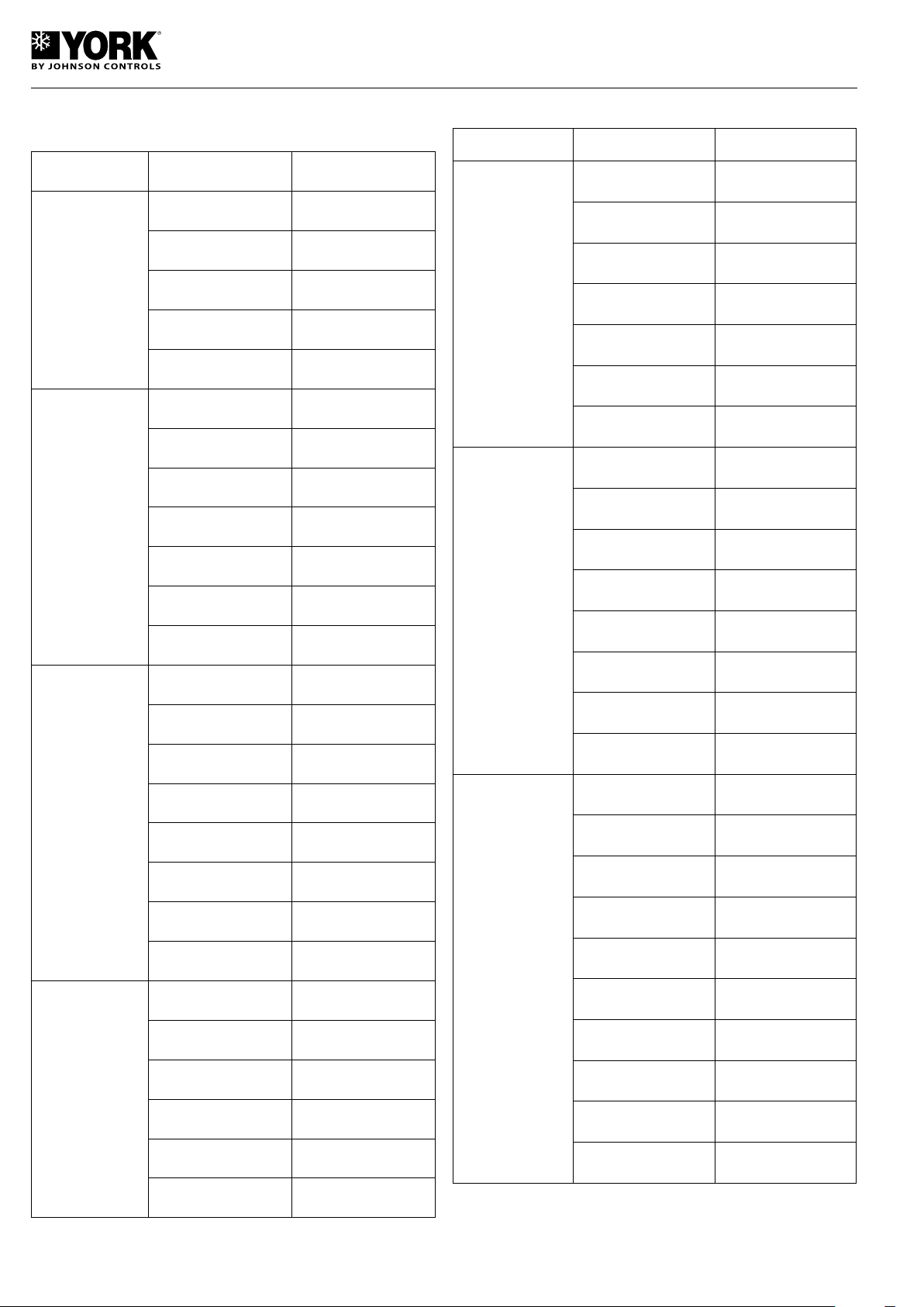
Table 6. Available pressure for hydraulic circuit
(without filter installed)
Model Flow l/h
DISP.
kPa
Table 6. (Cont.)
Model Flow l/h
DISP.
kPa
1 700 221
YLCA/
YLHA PLUS 05
YLCA/
YLHA PLUS 07
600 61
800 55
1 000 46
1 200 36
1 400 25
800 96
1 000 91
1 200 81
1 400 70
1 600 58
1 800 45
2 000 28
YLCA/
YLHA PLUS 15
YLCA/
YLHA PLUS 20
2 000 200
2 300 170
2 600 140
2 900 105
3 200 60
3 500 10
2 000 175
2 500 160
3 000 145
3 500 125
4 000 105
YLCA/
YLHA PLUS 09
YLCA/
YLHA PLUS 12
1 000 95
1 200 88
1 400 80
1 600 70
1 800 60
2 000 49
2 200 37
2 400 24
1 400 149
1 700 134
2 000 118
2 300 95
4 500 83
5 000 60
5 500 30
3 000 245
3 500 228
4 000 208
4 500 187
5 000 163
YLCA/
YLHA PLUS 27
5 500 140
6 000 112
6 500 83
7 000 49
18
2 600 62
2 900 30
7 500 15
Details with water at 10° C.
If using glycol, apply the correcting factors indicated in Table 8.
Page 19
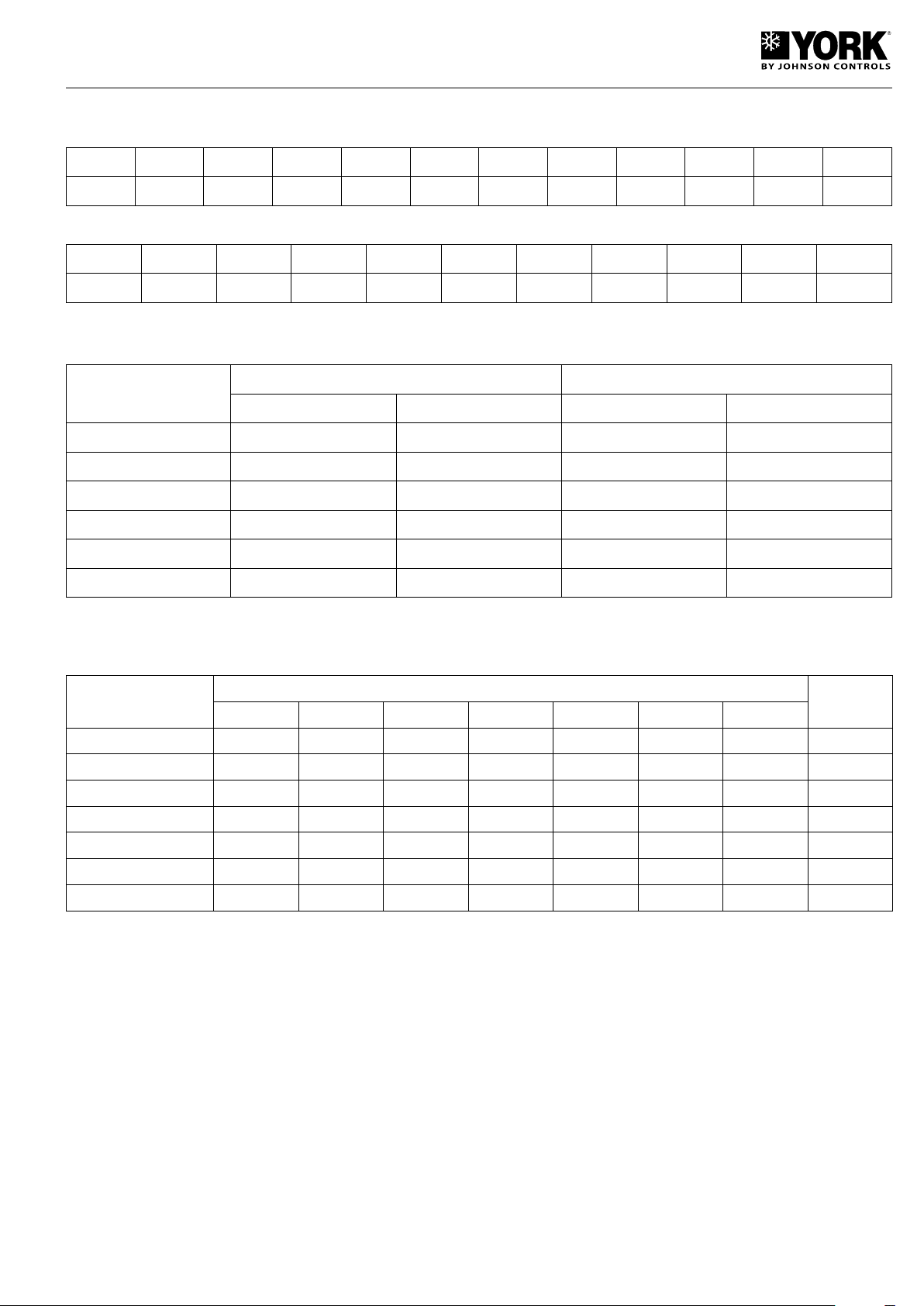
Table 7. Pressure drops of filters
1" filter
Flow l/h
kPa
600 800 1 000 1 200 1 400 1 600 1 800 2 000 2 200 2 400 2 600
0.7 1.4 2.6 4.3 6.4 8.9 11.8 15.1 18.8 22.8 27.1
1 1/4" filter
Flow l/h
kPa
Data with water at 10° C. In the case of using glycol, apply correcting factors indicated in table 8.
1 500 2 000 2 500 3 000 3 500 4 000 4 500 5 000 5 500 6 000
0.9 1.5 2.6 3.9 5.6 7.7 10.1 12.8 15.7 18.8
Table 8. Correcting factors for other glycol concentrations
% in weight
Capacity Absorbed power Capacity Absorbed power
10 1.061 1.025 1.097 1.033
20 1.036 1.015 1.067 1.023
30 1.015 1.005 1.026 1.008
35 1 1 1 1
40 0.985 0.995 0.974 0.992
50 0.954 0.985 0.923 0.977
Ethylene glycol Propylene glycol
If it is necessary to make this selection with different glycol percentages, correct the capacities and absorbed power in table 2 and 4 (35% ethylene glycol),
multiplying them by the coefficients indicated in table 8.
Table 9. Sound power spectrum
Models
YLCA/YLHA PLUS 5
YLCA/YLHA PLUS 7
YLCA/YLHA PLUS 9
YLCA/YLHA PLUS 12
YLCA/YLHA PLUS 15
YLCA/YLHA PLUS 20
YLCA/YLHA PLUS 27
The information appearing in this table is sound pressure values as per ISO EN3743.
125 250 500 1 000 2 000 4 000 8 000
66.2 70.5 67.7 65.7 60.2 55.1 48.8 70
66.2 70.5 67.7 65.7 60.2 55.1 48.8 70
74 72.3 67.9 66.1 61.8 56.3 52.3 71
79.6 74.3 70.2 67.5 62.7 57.7 51.0 73
79.6 74.3 70.2 67.5 62.7 57.7 51.0 73
77 72.4 72.9 69.1 63.9 58.2 52.5 74
75.6 81.3 75.9 70.8 68.6 63.3 55.7 78
Frequency (Hz)
dB(A)
19
Page 20
Selection guide (YLCA and YLHA PLUS)
Necessary information
The following information is needed to select a YLCA water
chiller:
1. Cooling capacity needed.
2. Design cold water input and output temperatures.
3. Design water flow, if any of the temperatures in above
point 2 is unknown.
4. Design input temperature of air to the condensing unit.
Normally, this will be the design ambient temperature of
summer air, unless influenced by the situation or other
factors.
5. Altitude above sea level.
6. Design gumming coefficient of the evaporating unit.
Taking a quick look at Table 1 we can see that a YLCA-5 unit
gives an approximate required capacity of 5.38 kW.
As the factors appearing in Tables 10 and 11 are not applicable, conditions will be as follows:
Cooling capacity: 5.38 kW
Power consumed: 1.87 kW
Water temperature: 13° C to 7° C (∆t = 6)
5.38 x 860
Water flow: = 771 l/h
6
Available pressure in hydraulic circuit of a unit.
- From Table 6 we infer that the YLCA - 5 MC, with a 771 l/h
flow, has an available pressure of 56 kPa.
Note: Points 1, 2 and 3 should be related by means of the
following formulae:
l/h cold water x °C differential
Cooling capacity kW =
860
Selection example
A chiller is required to chill water from 13° C to 7° C, with a
cooling capacity of 5 kW.
Here are other design conditions:
Ambient air entering the condensing unit: 35° C
Gumming coefficient: 0.044m2 °C/kW
Altitude: At sea level
Table 10. Gumming coefficients
Evaporating unit
Gumming coeff.
m2 °C/kW
0.044 1.000 1.000
0.088 0.987 0.995
0.176 0.964 0.985
0.352 0.926 0.962
Capacity factor
Comp. absorbed
power factor
Table 11. Altitude factors
Pressure drop in filter.
- From Table 7. 1" filter, we infer that with a 771 l/h flow, said
filter has a pressure drop of 1.3 kPa.
YLHA PLUS selection method
1. Determine the correct size of the YLHA PLUS unit by
selecting a model from Tables 3 and 5 that is closest to
the cooling and heating capacities required in the design
conditions of the water outlet and air intake temperatures.
2. Apply gumming correcting factors (Table 10) and altitude
(Table 11) to the capacity and power values that appear
in the corresponding capacity tables in cool and heat.
Make sure the corrected capacity is still sufficient for your
needs.
3. Using the corrected capacities of the unit, select the de-
sign temperature differential, or the flow.
4. Check to make sure that these selections are within the
YLCA/YLHA PLUS operating limits.
YLHA PLUS selection example
A YLHA PLUS 5 heat pump operating at a 35° C ambient
temperature should chill water from 13° C to 7° C, with a
5 kW cooling capacity.
A 4 kW heating capacity is required in 0° C design ambient temperature and a hot water output temperature of
45° C.
The gumming coefficient is 0.044 m² °C/kW, with the unit
operating at sea level (no corrections).
With a quick glance of capacity Tables 3 and 5, we see that
a YLHA PLUS 5 heat pump gives the approximate required
capacities:
Altitude (m) Capacity factor
0 1.000 1.000
600 0.987 1.010
1 200 0.973 1.020
1 800 0.958 1.029
2 400 0.943 1.038
20
Comp. absorbed
power factor
Cooling capacity = 5.40 kW
Total unit absorbed power = 1.91 kW
Cold water temperature = 13° C to 71 C (∆t: 6° C)
Hot and cold water flow = 774 l/h
Heating capacity = 4.15 kW
Total unit absorbed power
in heat mode = 1.88 kW
Hot water output temperature = 45° C
Hot water temp. 4.15 x 860
differential = = 4.60° C
774
Thus. hot water return
temperature is = 40.4° C
Page 21

All values are within operating limits.
- Available pressure in hydraulic circuit of a unit with hydro
kit.
- From Table 6 we infer that the YLHA PLUS 5, with a
748 l/h flow, has an available pressure of 56.5 kPa.
- Pressure drop in filter.
- From Table 7.1" filter, we infer that with a 748 l/h flow,
said filter has a pressure drop of 1.2 kPa.
Selection guide with glycol (cool only units)
Necessary information
The following information is needed to select a YLCA water
chiller:
1. Cooling capacity needed.
2. Design cold water/glycol input and output temperatures
to and from the condensing unit.
4. Always recheck to make sure these selections are within
the specified design operating limits.
Selection example
A chiller is required to chill ethylene glycol from 1 to -4° C,
with a capacity of 3.5 kW.
The following design conditions are applicable:
Gumming coefficient: 0.088m² °C/kW
Altitude: 1 200 m
Ambient air: 30° C
Concentration of glycol: 30% w/w
For a -4° C ethylene glycol output, the concentration recommended in Figure 1 is 30%. Therefore, the specified concentration is appropriate.
3. Design water/glycol flow.
4. Design input temperature of air to condensing unit.
Normally, this will be the design ambient temperature of
summer air, unless influenced by the situation or other
factors.
5. Altitude above sea level.
6. Design gumming coefficient of the evaporating unit.
Note: Points 1, 2 and 3 should be related by means of the
following formulae:
∆t (°C) x Flow (litres/second)
Capacity (kW) =
Glycol factor
In which ∆t = liquid intake temp. - liquid output temp.
To determine the glycol factor, please see Figure 1 for ethylene glycol, or Figure 3 for propylene glycol. For design
output temperature, please see the recommended glycol
concentration and the glycol factor in this concentration. This
is the minimum concentration to be used for design output
temperature. If a greater concentration is required, the glycol
factor can be determined by means of Figure 2 on ethylene
glycol or Figure 4 on propylene glycol.
Selection method
1. Determine the correct chiller model by selecting the one
that is closest to the capacities required by the design conditions of the glycol outlet and air intake temperature.
2. Apply the gumming correcting factors that correspond to
the gumming coefficient, altitude and glycol concentration,
and to the capacity and power values that appear in the
corresponding capacity tables. Make sure the corrected
capacity is still sufficient for your needs.
3. Using the corrected capacities of the chiller, set the design
temperature range, or the flow, to balance the formulae
appearing in the "Necessary Information" section.
From Table 2 (capacities with 35% glycol) we infer that a
YLCA - 5 unit, at the established design conditions, gives a
capacity of 3.44 kW and a consumption of 1.35 kW.
With the design gumming coefficient, use the capacity correcting factors x 0.987 and power x 0.995 (Table 10).
On design altitude, apply the capacity correcting factors x
10.973 and power x 1.020 (Table 11).
On design glycol concentration, apply the capacity correcting
factors x 1.015 and power x 1.005 (Table 3).
Applying these factors to the selection: YLCA - 5
Capacity = 3.44 x 0.987 x 0.973 x 1.015 = 3.35 kW
Comp. power = 1.35 x 0.995 x 1.020 x 1.005 = 1.37 kW
For the specified glycol concentration and a -4° C output
temperature. Figure 3 shows a 0.248 glycol factor. Thus, the
flow can be determined with the formula appearing in the
"Necessary Information" section.
(1 - (-4)) x Flow (l/s)
3.35 kW =
0.248
3.35 x 0.248
Flow = = 0.166 (l/s) or 598 (l/h)
5
This covers the limits of use.
The evaporating unit pressure drop can be determined by
taking the water pressure drop value (Table 7) for a YLCA
unit and multiplying it by the correcting factor (see Fig. 5)
for a 30% concentration and an average temperature of
-1.5° C, that is to say 1 + (-4)
= -1.5
2
42 kPa x 1.22 = 51.2 kPa
21
Page 22
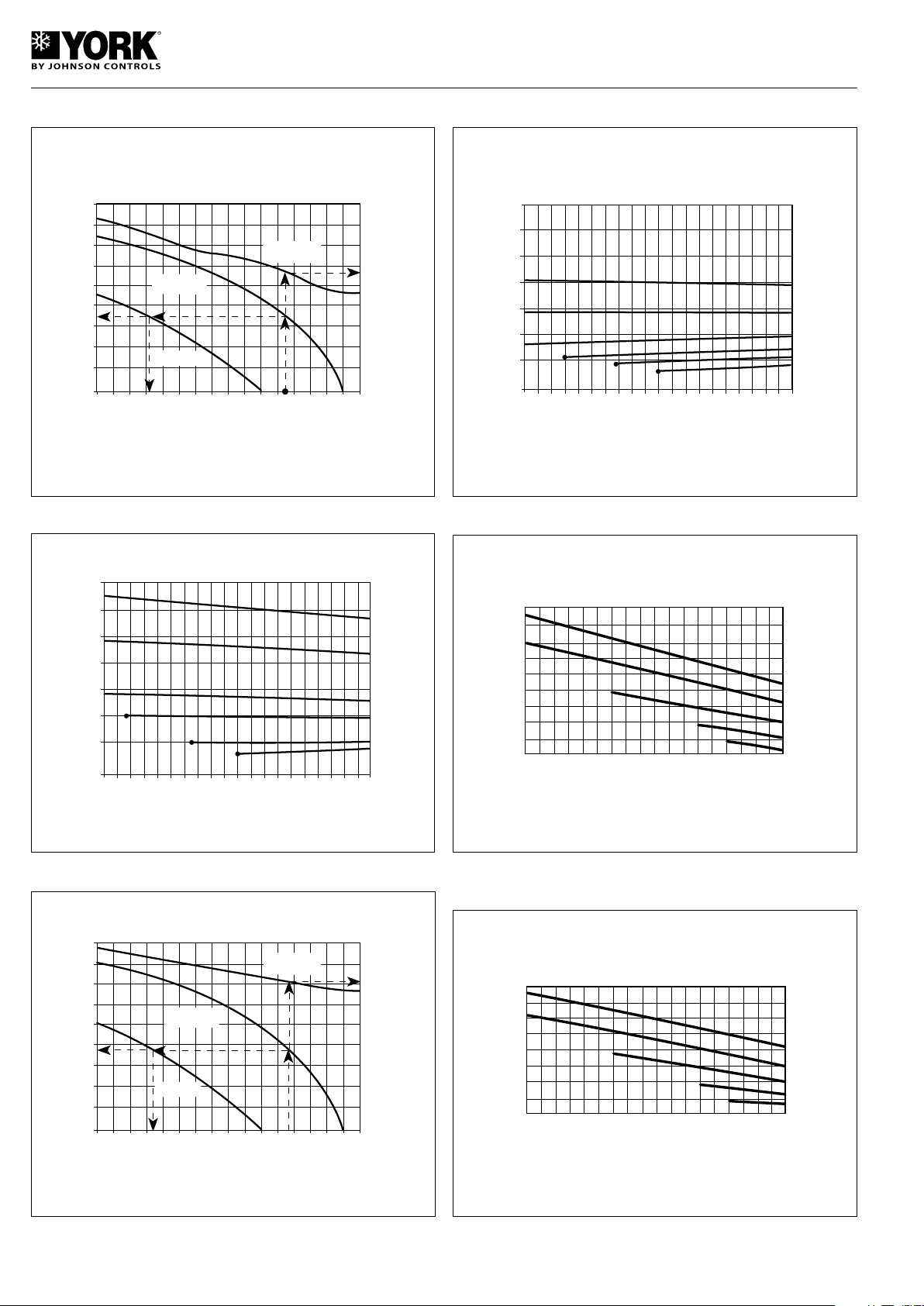
Fig. 1 - Recommended ethylene glycol concentrations
-10 -8 -6 -4 -2 0 2 4 6
0
5
10
15
20
25
30
35
40
45
0.23
0.24
0.25
0.26
0.27
0.28
OUTPUT LIQUID TEMPERATURE °C
% BY WEIGHT
GLYCOL FACTOR l/s °C/kW IN
RECOMMENDED CONCENTRATIONS
GLYCOL FACTOR IN
RECOMMENDED
CONCENTRATIONS
RECOMMENDED
CONCENTRATION
% BY WEIGHT
FREEZING
POINT
GLYCOL FACTOR
-10 -8 -6 -4 -2 0 2 4
6
0.23
0%
OUTPUT LIQUID TEMPERATURE °C
0.24
0.25
0.26
0.27
0.28
0.29
0.30
8 10
10%
20%
30%
40%
50%
GLYCOL FACTOR
-10 -8 -6 -4 -2 0 2 4 6
0
5
10
15
20
25
30
35
40
45
0.24
0.25
0.26
OUTPUT LIQUID TEMPERATURE °C
% BY WEIGHT
GLYCOL FACTOR l/s °C/kW IN
RECOMMENDED CONCENTRATIONS
GLYCOL FACTOR IN
RECOMMENDED
CONCENTRATIONS
RECOMMENDED
CONCENTRATION
% BY WEIGHT
FREEZING
POINT
0.23
-10 -8 -6 -4 -2 0 2 4
6
0.23
0%
OUTPUT LIQUID TEMPERATURE °C
0.24
0.25
0.26
0.27
0.28
0.29
0.30
8 10
10%
20%
30%
40%
50%
GLYCOL FACTOR
GLYCOL FACTOR
-10 -8 -6 -4 -2 0 2 4
6
LIQUID AVERAGE TEMPERATURE °C
CONCENTRATION OF GLYCOL P/P
8
10%
20%
30%
40%
50%
CORRECTING FACTOR
1.50
1.45
1.40
1.35
1.30
1.25
1.20
1.15
1.10
1.05
-10 -8 -6 -4 -2 0 2 4
6
1.0
LIQUID AVERAGE TEMPERATURE °C
CONCENTRATION OF GLYCOL P/P
8
10%
20%
30%
40%
50%
CORRECTING FACTOR
1.1
1.2
1.3
1.4
1.5
1.6
1.7
1.8
Fig. 4 - Propylene glycol in other concentrations
Fig. 2 - Ethylene glycol in other concentrations
Fig. 3 - Recommended propylene glycol concentrations
Fig. 5 - Ethylene glycol pressure drop correcting factor
Fig. 6 - Propylene glycol pressure drop correcting factors
22
Page 23
Installation instructions
CAUTION
Inspection
Upon reception, inspect the goods and notify the carrier and
the insurance company, in writing, of any possible damage
during transportation.
Environmental protection
Packing
Packing is made of recyclable material. Its elimination should
be carried out in accordance with local regulations on selective collection of residual material.
Refrigerant
Contains greenhouse effect fluorided gas covered by
the Kyoto protocol.
For the type of gas and quantity per system, see the identification plate.
GWP (global warming potential): 2088.
Elimination of the unit
Upon disassembly of the unit, the components should be
recuperated ecologically. The cooling circuit is full of refrigerant that should be recuperated and returned to the gas
manufacturer for recycling.
Oil will remain in the hermetic compressor and, therefore,
must be returned with its circuit sealed.
The air conditioning unit will be deposited in an area determined by the local authorities, for its selective recuperation.
Handling
The unit should be handled using the metal rails supplied for
fastening and transportation.
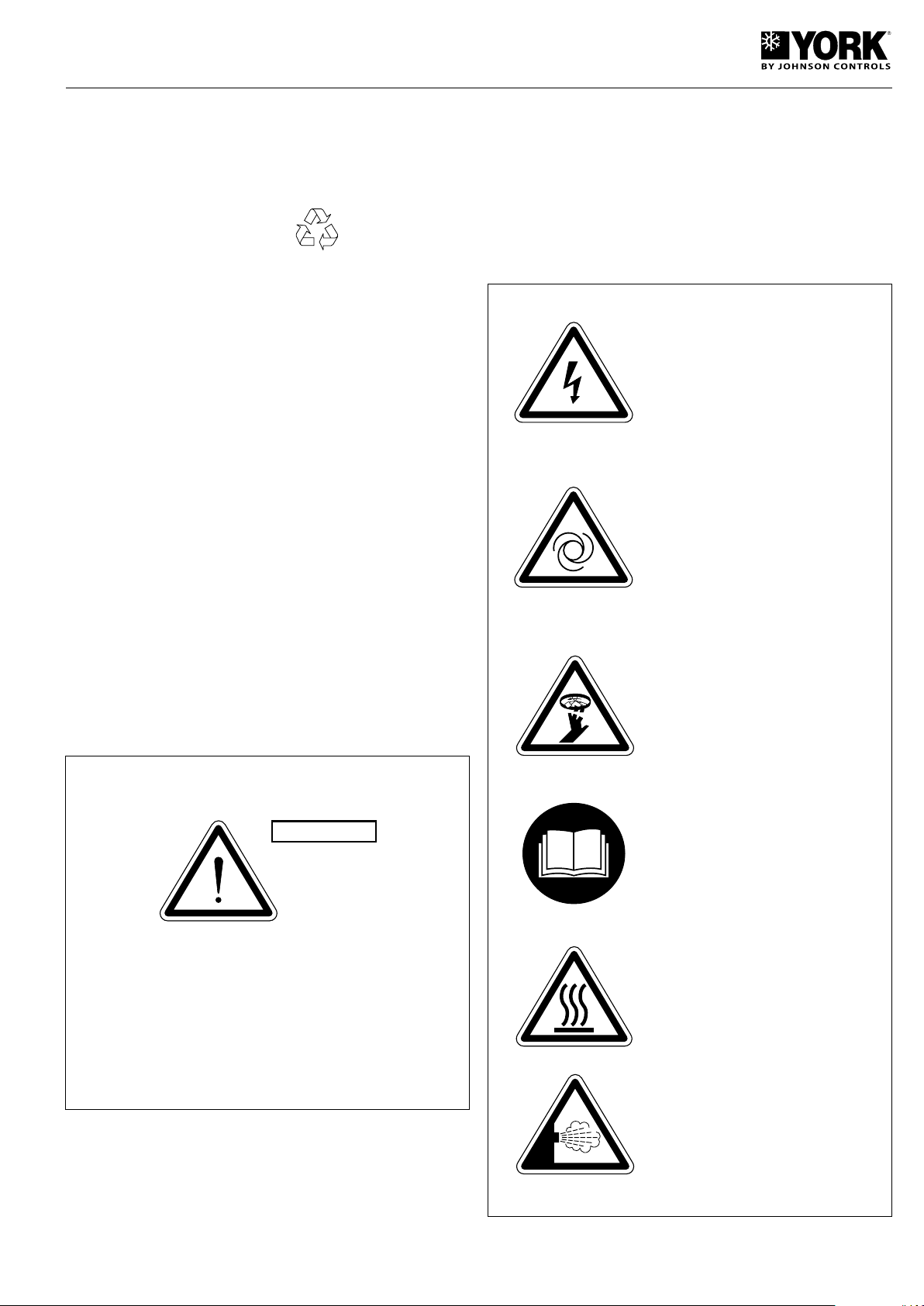
Warning signs
The following signs indicate the existence of potentially
dangerous conditions for users or servicing personnel.
Whenever found on the unit, take the meaning of each one
into account.
This symbol indicates an electrical danger
or risk.
Caution: The unit is equipped with remote
control system and can start automatically.
Before accessing the interior, disconnect
the power supply so as to avoid any contact with the fan turbine in motion.
Safety
Installation and maintenance servicing of this air conditioning
system should be carried out by qualified and expert personnel. Maintenance servicing, such as cleaning coils and air
filters, should be carried out regularly to maintain optimum
performance of the units.
This unit should be installed and used in compliance with:
- Low voltage electro-technical regulations.
- Safety regulations for cooling plants and installations.
- Pressure device regulations.
- Basic building regulations.
- Local regulations.
Caution: Fan in operation.
Caution: It is obligatory to read the instructions prior to any handling.
Caution: Do not touch hot surfaces.
Transportation
The units should always be transported in vertical position so
as to avoid oil leaking out of the compressor. If, for any reason,
this position need be changed sporadically, they will remain
in that position a strictly necessary period of time only.
Caution: Possible gas leak due to inadequate handling.
23
Page 24
Location
OK
NO
WITH ANTI-SNOW GRIDS
(HIGH PLATFORM)
WITHOUT ANTI-SNOW
GRIDS (LOW PLATFORM)
NO
Before locating the unit, make sure you have received the
appropriate product by checking the specifications described
on the outside of same.
The unit should be placed on a perfectly horizontal plane,
making sure the base can support the weight of the unit.
If vibration-free operation is required, the unit can be placed
on a cork or similar anti-vibratory base, or fastened to the
base with anti-vibratory plates or supports.
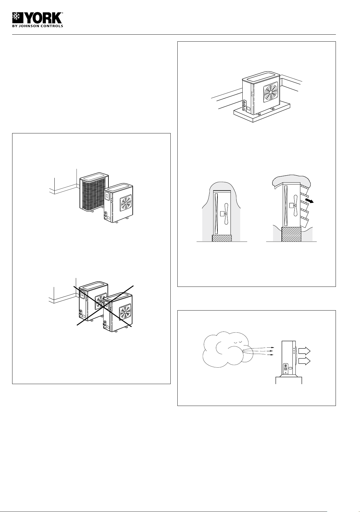
Location of several units
Avoid the recirculation of air between units.
YLCA/YLHA PLUS 5, 7, 9, 12, 15, 20 and 27
Fastening the unit
Before installing the unit, make sure the structure can support
the weight of same.
If the unit is to be placed on the floor, a concrete base should
be prepared so as to distribute weight evenly.
Place the unit on a consistent base and fasten by means of
bolts, using the four drilled holes at the base of the unit. Areas
where it snows regularly. If the unit is located outdoors and
at ground level, it should be placed on supports so as to avoid
obstruction of the air flow by an accumulation of snow. These
supports should be above the height the snow normally
reaches. It is convenient to install anti-snow grids.
Orientation
Orient the unit in the direction of the predominating winds.
Clearances
When installing each unit, clearances should be left for:
a) Air intake and discharge.
b) Maintenance servicing.
c) Power supply connections.
For proper operation, all minimum clearances shown on the
general dimension diagrams should be respected always
with regard to possible obstruction of air circulation of the
work of a user.
24
Page 25
Wiring
WARNING
Electrical connections
All established national regulations should be complied.
Each unit is supplied with a control box to which the power
supply will be connected through a fused main switch or an
automatic switch.
Loose cables can cause overheating of terminals or incorrect operation of the unit. Fire hazards may also exist. Therefore, make sure
all cables are connected firmly.
Rotational direction of Scroll compressors
The Scroll compressors operate correctly in one single rotational direction. Although these units are protected by a phase
order detector, when starting the equipment make sure the
rotational direction is correct.
If it is not correct:
- The compressor does not compress.
- It makes a strange sound.
- Amperage consumption is limited.
- It overheats in excess.
The phase detector should have the led son for operation
to be correct.
- Green led on means: Power ON.
- Yellow led on means: Relay ON.
Hydraulic connections
The hydraulic connections of the water intake and outlet of
the unit should be carried out respecting the intake and outlet
directions indicated.
A galvanised iron or copper tubing can be used, with dimensions no lower than those indicated, and keeping in mind
the pressure drops at said connections and in the internal
exchanger of the installation.
During the winter season, with outdoor temperatures below
0° C, take precautions to avoid freezing of the water in the
tubing network.
Usually, a solution is filling the circuit with an antifreeze
mixture (glycol).
25
Page 26
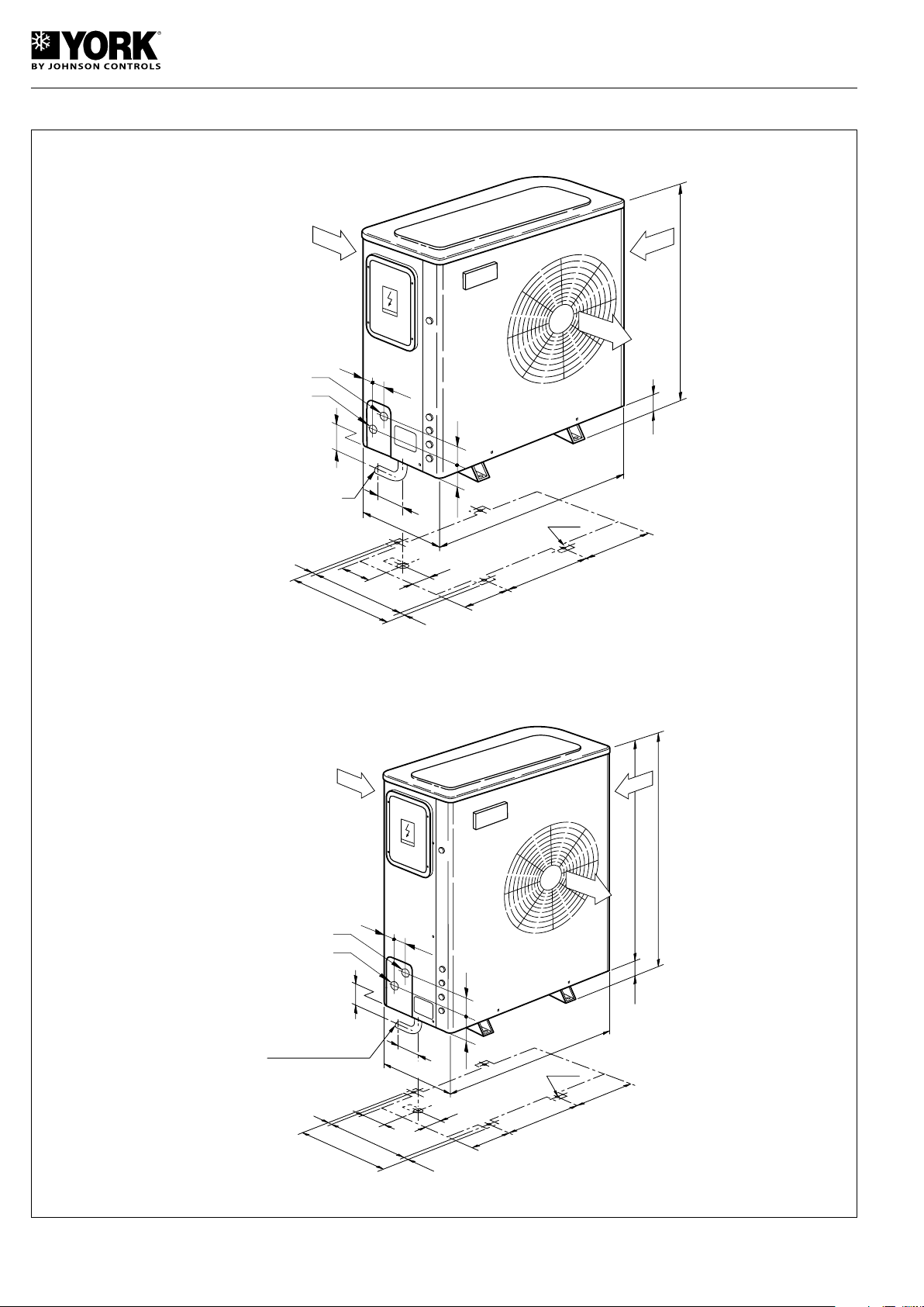
General dimensions mm and hydraulic connections
762
32
905
405
10
323
152
430
440
10
460
Ø 11.5
17
.
5
31
66
66
90 80
55
47
DRAIN CONNECTION
EXT. Ø 15
WATER INTAKE 1”G
WATER OUTLET 1”G
90
55
47
32
905
405
323
152
430
440
10
460
10
Ø 11.5
17.5
31
66
66
933
965
80
DRAIN CONNECTION
EXT. Ø 15
WATER INTAKE 1”G
WATER OUTLET 1”G
YLCA/YLHA PLUS 5
YLCA/YLHA PLUS 7 - 9
26
Page 27
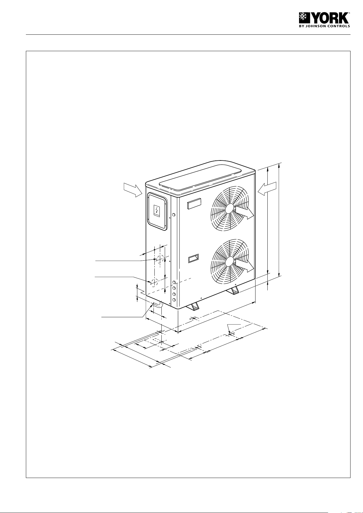
General dimensions mm and hydraulic connections
1270
32
1238
405
905
323
152
430
440
10
460
10
Ø 11.5
17.5
31
66
66
90 675
55
26
DRAIN CONNECTION
EXT.Ø 15
WATER INTAKE 1”G
WATER OUTLET 1”G
YLCA/YLHA PLUS 12 and 15
27
Page 28
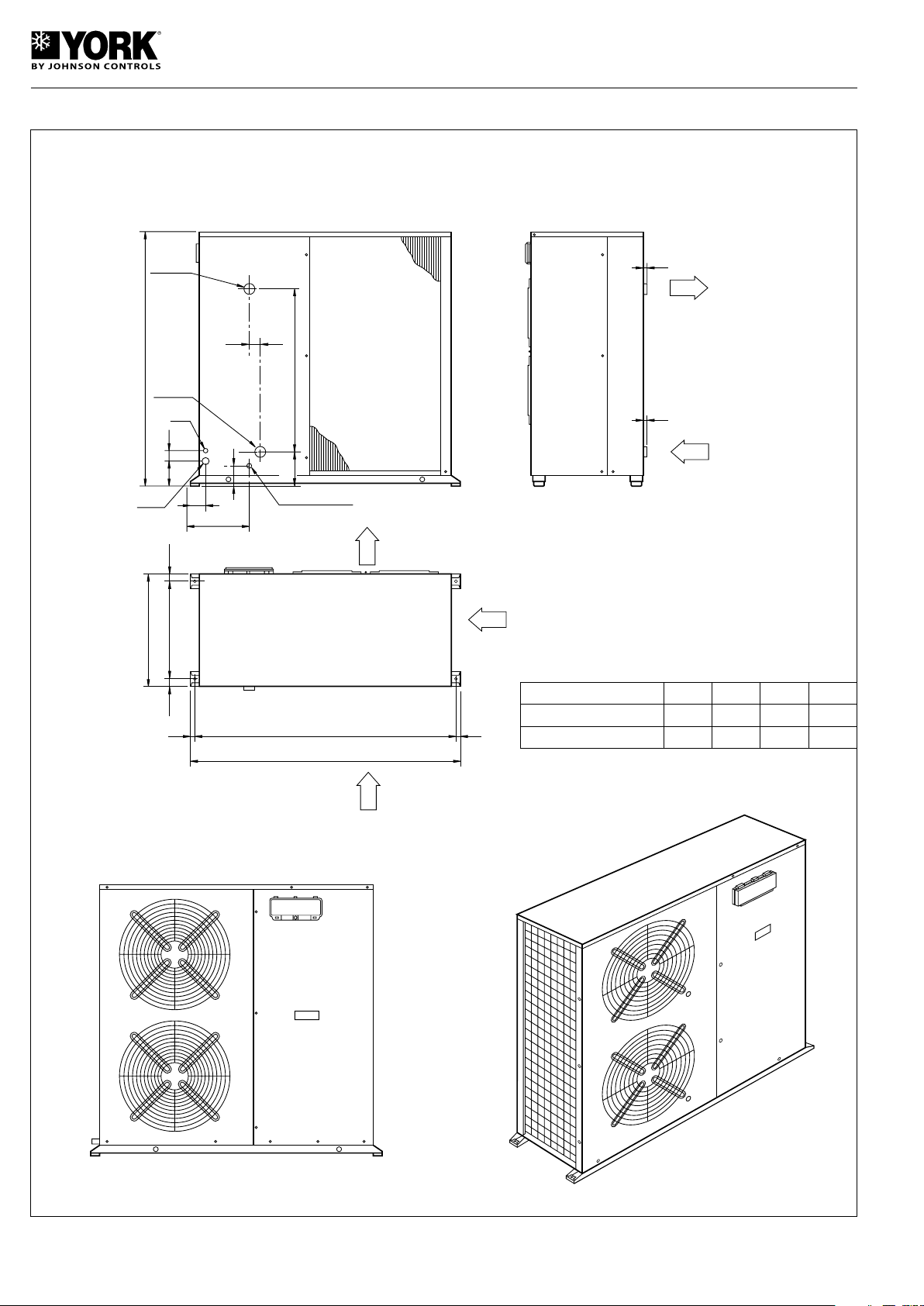
General dimensions mm and hydraulic connections
FRONT VIEW
15
15
18
18
415
43.5
502
1 1/4"GF
75
43.5
Ø38
D
89
160
50
90
Ø31
577
1 1/4"GF
1 270
A
B
C
SEEN FROM ABOVE
WATER
INTAKE
WATER
OUTLET
REAR VIEW
AIR
INTAKE
AIR
INTAKE
AIR
OUTLET
SIDE VIEW
WATER DRAIN
YLCA/YLHA PLUS 20 and 27
YLCA/YLHA PLUS-20
YLCA/YLHA PLUS-27
1 430 1 394 136 428
1 876 1 840 144 432
A B C D
28
Page 29
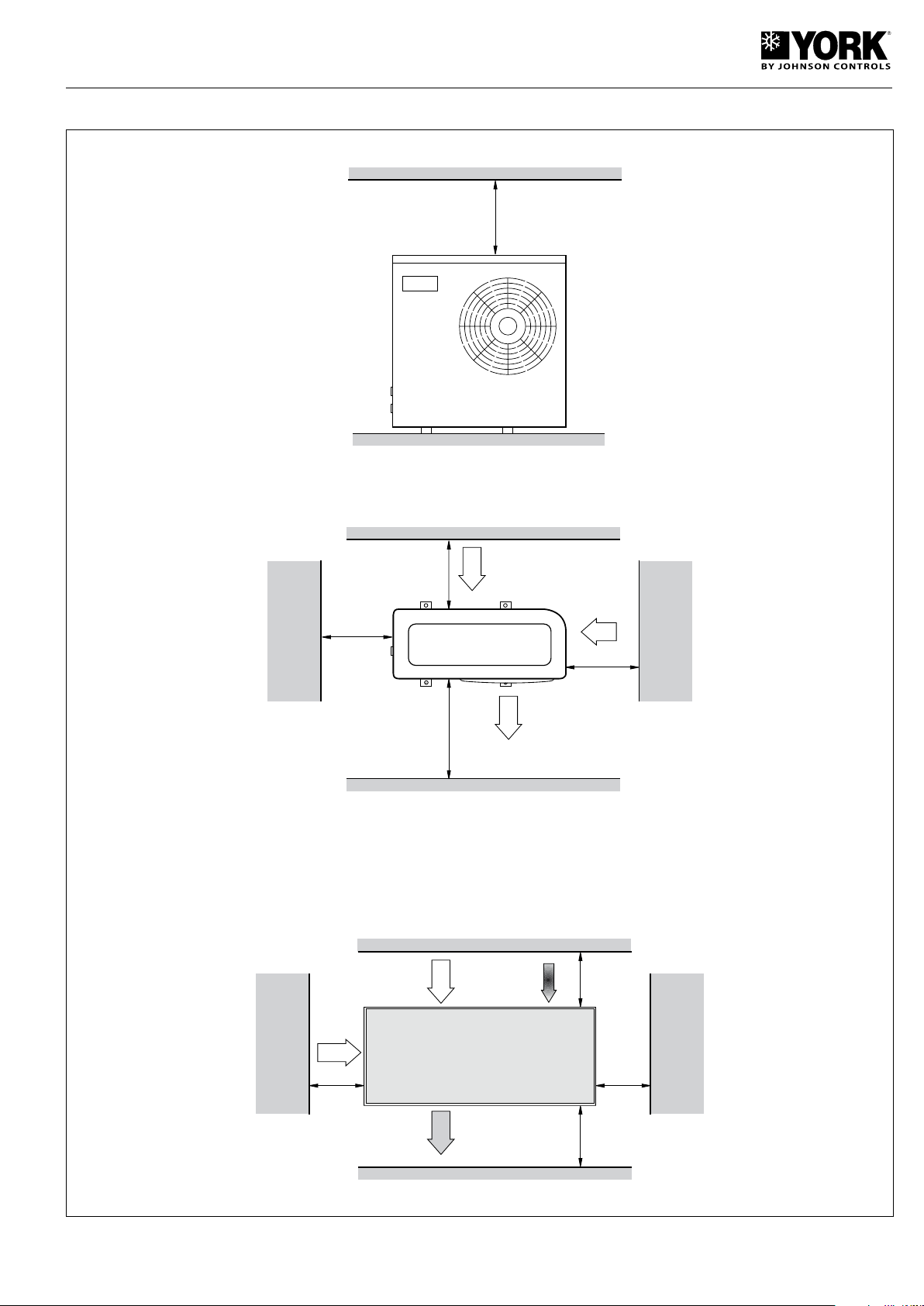
Minimum technical clearances mm
300
600
300
WATER INTAKE
AND OUTLET
800
YLCA 5, 7, 9, 12 and 15
YLCA/YLHA PLUS 20 and 27
29
Page 30
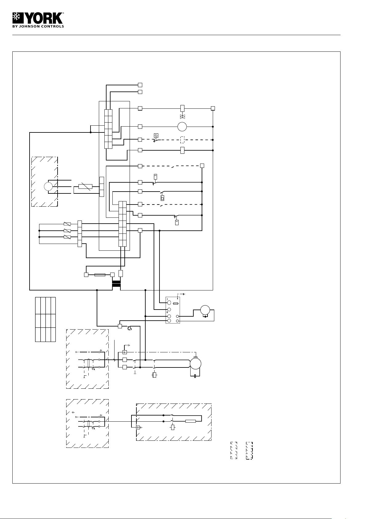
Wiring diagram, YLCA/YLHA PLUS 5, 7, 9 MC and M, 230.1.50
I-2531h
YLCA/YLHA PLUS 5, 7, 9 MC and M
230.1.50
C2 CONDENSADOR VENTILADOR
FAN CONDENSER
F1 FUSIBLE PROTECCIÓN CONTROL
ELECTRONICO / MANIOBRA 24V
24V ELECTRONIC CONTROL FUSE
F2 FUSIBLE PROTECCIÓN VARIADOR DE
VELOCIDAD VENTILADOR
FAN SPEED CONTROLLER FUSE
FS CONTROL CAUDAL DE AGUA (UNIDADES MC)
WATER FLOW SWITCH (MC UNITS)
FSC VARIADOR VELOCIDAD VENTILADOR
FAN SPEED CONTROLLER
HP PRESOSTATO ALTA 41 BAR
HIGH PRESSURE SWITCH, 41 BAR
HTP PROTECTOR TÉRMICO RESISTENCIA
HEATER THERMAL PROTECTION
K1 CONTACTOR COMPRESOR
COMPRESSOR CONTACTOR
K2 CONTACTOR RESISTENCIA AUXILIAR
AUXILIARY HEATER CONTACTOR
LAK ACCESORIO LOW AMBIENT
KIT PRESOSTATICO
LOW AMBIENT KIT, ACCESSORY
LP PRESOSTATO BAJA 2,5 BAR
LOW PRESSURE SWITCH, 2.5BAR
M1 COMPRESOR
COMPRESSOR
M2 VENTILADOR
FAN
M3 BOMBA (UNIDADES MC)
PUMP (MC UNITS)
MS INTERRUPTOR GENERAL
MAIN SWITCH
Q1 PROTECTOR MAGNETOTÉRMICO
RESISTENCIA APOYO
BACKUP HEATER MAGNETO THERMAL
PROTECTOR
Q2 PROTECTOR MAGNETOTÉRMICO GENERAL /
COMPRESOR
MAIN MAGNETO THERMAL PROTECTOR,
COMPRESSOR
Q3 PROTECTOR MAGNETOTÉRMICO MANIOBRA
GENERAL 230V / VENTILADOR / BOMBA /
RESISTENCIA CARTER
MAIN OPERATING MAGNETO THERMAL
PROTECTOR, 220V/FAN/PUMP.
SUMP HEATER
R00 SELECTOR REMOTO PARO / MARCHA
ON/OFF REMOTE CONTROL
RCH SELECTOR REMOTO FRIO / CALOR
COOL/HEAT REMOTE CONTROL
T TRANSFORMADOR 230 / 24V 20VA
230 / 24V 20VA TRANSFORMER
V4V VALVULA DE 4 VIAS
4-WAY VALVE
LOS COMPONENTES INCLUIDOS EN ESTOS RECUADROS SON
ACCESORIOS STANDARD SUMINISTRADOS POR EL FABRICANTE
LOS COMPONENTES INCLUIDOS EN ESTOS RECUADROS NO SON
SUMINISTRADOS POR EL FABRICANTE
1.- ALARMA. CONTACTO NORMALMENTE ABIERTO LIBRE DE TENSIÓN
(3A.RESISTIVOS MÁXIMO)
ALARM.CONTACT NORMALLY OPEN, VOLT-FREE (3A. MAXIMUM RESISTANCE.)
2.- SONDA TEMPERATURA EXTERIOR EN UNIDADES CON LAK (NTC)
SONDA TEMPERATURA BATERIA EN UNIDADES ESTANDARD (NTC)
OUTDOOR TEMPERATURE PROBE ON UNITS WITH LAK (NTC)
COIL TEMPERATURE PROBE ON STANDARD UNITS (NTC)
NOTAS:
NOTES:
THE COMPONENTS INCLUDED IN THESE BOXES ARE NOT SUPPLIED
BY THE MANUFACTURER.
THE COMPONENTS INCLUDED IN THESE BOXES ARE STANDARD
ACCESSORIES SUPPLIED BY THE MANUFACTURER.
3.-
TRANSDUCTOR DE PRESION RACIOMETRICO EN UNIDADES CON LAK
SONDA TEMPERATURA EXTERIOR EN UNIDADES ESTANDARD (NTC)
RATIOMETRIC PRESSURE TRANSDUCER ON UNITS WITH LAK,
OUTDOOR TEMPERATURE PROBE ON STANDARD UNITS (NTC)
4.-
SOLO UNIDADES MC
MC UNITS ONLY
L1
L1
N
N
Q2
Amp
230V, 1 ~,50Hz,N, PE
L1
R
L1
L1
N
N
Q1
230V, 1 ~,50Hz,N,
K2
(15)
AH
2
1
4
3
N
M1
K1
(14)
C
S
A1
A2
C1
MS
1
C2
M2
F1
F1
F1
315 mA
(LENTO)
(SLOW)
GO
GND
D4 D2 D1 D3
D5
GND
N1 C
1
/
2
C5
N2
C
1
/
2
C
3
/
4
N3 N4 N5
C
3
/
4
1 2 3 4 5 6
7 8 9 10 11 12
A1
A2
(1)
COMPRESOR
COMPRESSOR
N1
RESISTENCIA AUXILIAR
AUXILIARY HEATER
VALVULA DE 4 VIAS
4-WAY VALVE
N4
BOMBA (NOTA - 4)
PUMP (NOTE 4)
N3 N5 C5
GO
G
B1
GND
B2
GND
B3
Y
ID5
GND
ID3
ID4
ID1
ID2
B1 B2 B3
ENTRADA AGUA
WATER INTAKE
SALIDA AGUA
WATER OUTLET
(NOTA 2)
(NOTE 2)
B1 B2 B3
GND
B4 V+GND
B4
VERDE
GREEN
BLANCO
WHITE
NEGRO
BLACK
LAK (ACCESORIO)
(PRESIÓN)
LAK (ACCESSORY)
PRESSURE
J1
10 9 8
7 5 4 3
2 1
11121314
6
J2
4 5 6
7
8 999 10 11 12 13 14 15 16 17 18
L1 N
1 2 30
2
1
4
3
TEMP. EXTERIOR
OUTLET TEMPERATURE
(NOTA 1)
(NOTE 1)
(NOTA 3)
(NOTE 3)
B4
(NOTA - 4)
(NOTE - 4)
A CONTROL ELECTRÓNICO
ELECTRONIC CONTROL
AH RESISTENCIA AUXILIAR
AUXILIARY HEATER
B1 SONDA TEMPERATURA ENTRADA AGUA (NTC)
WATER INTAKE TEMPERATURE PROBE (NTC)
B2 SONDA TEMPERATURA SALIDA AGUA (NTC)
WATER OUTLET TEMPERATURE PROBE (NTC)
B3 SONDA TEMPERATURA (VER NOTA 2) (NTC)
TEMPERATURE PROBE (SEE NOTE 2) (NTC)
B4 (VER NOTA 3)
(SEE NOTE 3)
C1 CONDENSADOR COMPRESOR
COMPRESSOR CONDENSER
Q3
3A
FSC
LOAD
F2
L N Y
GND
T
230V
0V
20 VA
FS
P
HP
41
bar
R00
RCH
K1
M3
V4V
(SOLO YLHA)
2
UNITS
5
7
Q2
20
25
9
32
"B" mm
2
Cu
2,5
4
6
INSTALAR
EN OBRA
INSTALL
AT JOB
SITE
chiller
2
"B" mm Cu
2
P
LP
2,5
bar
A
24
(YLHA ONLY)
INSTALAR
EN OBRA
INSTALL
AT JOB
SITE
(0)
N2
HTP
K2
30
Page 31
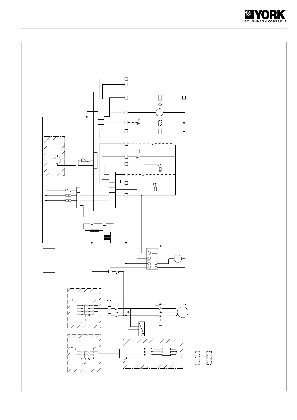
Wiring diagram, YLCA/YLHA PLUS 7, 9 TC and T, 400.3.50
I-2545g
YLCA/YLHA PLUS 7, 9 TC and T
400.3.50
"B" mm Cu
2
L1
L1
L2
Q1
400V, 3 ~,50Hz,
K2
(17)
AH
2
1
4
3
MS
1
F1
F1
F1
315 mA
(LENTO)
(SLOW)
GO
GND
D4 D2 D1 D3
P
LP
2,5
bar
D5
GND
N1 C
1
/
2
C5
N2
C
1
/
2
C
3
/
4
N3 N4 N5
C
3
/
4
1 2 3 4 5 6
7 8 9 10 11 12
A1
A2
(2)
N1 N4N3 N5 C5
GO
G
B1
GND
B2
GND
B3
Y
ID5
GND
ID3
ID4
ID1
ID2
B1 B2 B3
B1 B2 B3
GND
B4 V+GND
B4
J1
10 9 8
7 5 4 3
2 1
11121314
6
J2
4 5 6 7
8 9 10 11 12 13 14 15 16 17 18
L1
L3
L2 L3
L2 L3
5
6
A1
A2
3
1 2 30
C2
19 20
B4
M2
M1
K1
(16)
A1
A2
(5)
3 ~
F1 FUSIBLE PROTECCIÓN CONTROL
ELECTRONICO / MANIOBRA 24V
24V ELECTRONIC CONTROL FUSE
F2 FUSIBLE PROTECCIÓN VARIADOR DE
VELOCIDAD VENTILADOR
FAN SPEED CONTROLLER FUSE
FC CONTROL DE FASES
PHASE CONTROL
FS CONTROL CAUDAL DE AGUA (UNIDADES TC)
WATER FLOW SWITCH (TC UNITS)
FSC VARIADOR VELOCIDAD VENTILADOR
FAN SPEED CONTROLLER
HP PRESOSTATO ALTA 41 BAR
HIGH PRESSURE SWITCH, 41 BAR
HTP PROTECTOR TÉRMICO RESISTENCIA
HEATER THERMAL PROTECTION
K1 CONTACTOR COMPRESOR
COMPRESSOR CONTACTOR
K2 CONTACTOR RESISTENCIA AUXILIAR
AUXILIARY HEATER CONTACTOR
LAK ACCESORIO LOW AMBIENT
KIT PRESOSTATICO
LOW AMBIENT KIT, ACCESSORY
LP PRESOSTATO BAJA 2,5 BAR
LOW PRESSURE SWITCH, 2.5BAR
M1 COMPRESOR
COMPRESSOR
M2 VENTILADOR 1
FAN 1
M3 BOMBA (UNIDADES TC)
PUMP (TC UNITS)
MS INTERRUPTOR GENERAL
MAIN SWITCH
Q1 PROTECTOR MAGNETOTÉRMICO
RESISTENCIA APOYO
BACKUP HEATER MAGNETO THERMAL
PROTECTOR
Q2 PROTECTOR MAGNETOTÉRMICO GENERAL /
COMPRESOR
MAIN MAGNETO THERMAL PROTECTOR,
COMPRESSOR
Q3 PROTECTOR MAGNETOTÉRMICO MANIOBRA
GENERAL 230V / VENTILADOR / BOMBA /
RESISTENCIA CARTER
MAIN OPERATING MAGNETO THERMAL
PROTECTOR, 220V/FAN/PUMP.
SUMP HEATER
R00 SELECTOR REMOTO PARO / MARCHA
ON/OFF REMOTE CONTROL
RCH SELECTOR REMOTO FRIO / CALOR
COOL/HEAT REMOTE CONTROL
T TRANSFORMADOR 230 / 24V 20VA
230 / 24V 20VA TRANSFORMER
V4V VALVULA DE 4 VIAS
4-WAY VALVE
LOS COMPONENTES INCLUIDOS EN ESTOS RECUADROS SON
ACCESORIOS STANDARD SUMINISTRADOS POR EL FABRICANTE
LOS COMPONENTES INCLUIDOS EN ESTOS RECUADROS NO SON
SUMINISTRADOS POR EL FABRICANTE
1.- ALARMA. CONTACTO NORMALMENTE ABIERTO LIBRE DE TENSIÓN
(3A.RESISTIVOS MÁXIMO)
ALARM.CONTACT NORMALLY OPEN, VOLT-FREE (3A. MAXIMUM RESISTANCE.)
2.- SONDA TEMPERATURA EXTERIOR EN UNIDADES CON LAK (NTC)
SONDA TEMPERATURA BATERIA EN UNIDADES ESTANDARD (NTC)
OUTDOOR TEMPERATURE PROBE ON UNITS WITH LAK (NTC)
COIL TEMPERATURE PROBE ON STANDARD UNITS (NTC)
NOTAS:
NOTES:
THE COMPONENTS INCLUDED IN THESE BOXES ARE NOT SUPPLIED
BY THE MANUFACTURER.
THE COMPONENTS INCLUDED IN THESE BOXES ARE STANDARD
ACCESSORIES SUPPLIED BY THE MANUFACTURER.
3.- TRANSDUCTOR DE PRESION RACIOMETRICO EN UNIDADES CON LAK
SONDA TEMPERATURA EXTERIOR EN UNIDADES ESTANDARD (NTC)
RATIOMETRIC PRESSURE TRANSDUCER ON UNITS WITH LAK,
OUTDOOR TEMPERATURE PROBE ON STANDARD UNITS (NTC)
4.- SOLO UNIDADES TC
TC UNITS ONLY
(NOTA 1)
(NOTE 1)
COMPRESOR
COMPRESSOR
RESISTENCIA AUXILIAR
AUXILIARY HEATER
VALVULA DE 4 VIAS
4-WAY VALVE
BOMBA (NOTA - 4)
PUMP (NOTE 4)
(NOTA - 4)
(NOTE - 4)
VERDE
GREEN
BLANCO
WHITE
NEGRO
BLACK
LAK (ACCESORIO)
(PRESIÓN)
LAK (ACCESSORY)
PRESSURE
TEMP. EXTERIOR
OUTLET TEMPERATURE
(NOTA 3)
(NOTE 3)
ENTRADA AGUA
WATER INTAKE
SALIDA AGUA
WATER OUTLET
(NOTA 2)
(NOTE 2)
(0)
N2
HTP
Q3
3A
FSC
LOAD
F2
L N Y
GND
T
230V
0V
20 VA
FS
P
HP
41
bar
R00
RCH
K1
V4V
2
UNITS
7
9
Q2
10
10
"B" mm
2
Cu
2,5
2,5
chiller
2
FC
(8)
L1
L3
L2
14
11
FC
(1)
A
M
3
L1 L2 L3 N
24
21
22
1
2
3
4
5
6
L1
L1
N
N
Q2
Amp
400V, 3 ~,50Hz,N,
L2 L3
L2 L3
A CONTROL ELECTRÓNICO
ELECTRONIC CONTROL
AH RESISTENCIA AUXILIAR
AUXILIARY HEATER
B1 SONDA TEMPERATURA ENTRADA AGUA (NTC)
WATER INTAKE TEMPERATURE PROBE (NTC)
B2 SONDA TEMPERATURA SALIDA AGUA (NTC)
WATER OUTLET TEMPERATURE PROBE (NTC)
B3 SONDA TEMPERATURA (VER NOTA 2) (NTC)
TEMPERATURE PROBE (SEE NOTE 2) (NTC)
B4 (VER NOTA 3)
(SEE NOTE 3)
C2 CONDENSADOR VENTILADOR
FAN CONDENSER
C2 CONDENSADOR VENTILADOR
FAN CONDENSER
(SOLO YLHA)
(YLHA ONLY)
INSTALAR
EN OBRA
INSTALL
AT JOB
SITE
K2
31
Page 32
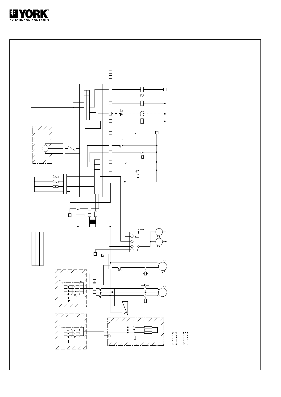
Wiring diagram, YLCA/YLHA PLUS 12 and 15 TC and T, 400.3.50
I-2533i
YLCA/YLHA PLUS 12, 15 TC and T
400.3.50
"B" mm Cu
2
L1
L1
L2
Q1
400V, 3 ~,50Hz,
K2
(17)
AH
2
1
4
3
MS
1
F1
F1
GO
GND
D4 D2 D1 D3
P
LP
2,5
bar
D5
GND
N1 C
1
/
2
C5
N2
C
1
/
2
C
3
/
4
N3 N4 N5
C
3
/
4
1 2 3 4 5 6
7 8 9 10 11 12
A1
A2
(2)
N1 N4N3 N5 C5
GO
G
B1
GND
B2
GND
B3
Y
ID5
GND
ID3
ID4
ID1
ID2
B1 B2 B3
B1 B2 B3
GND
B4 V+GND
B4
J1
10 9 8
7 5 4 3
2 1
11121314
6
J2
4 5 6 7
8 9 10 11 12 13 14 15 16 17 18
L1
L3
L2 L3
L2 L3
5
6
A1
A2
M4
K3
(18)
1
~
M1
K1
(16)
A1
A2
(
5
)
3
~
3
1
5
(3)
1 2 30
C3
M3
C2
M2
19 20
B4
F1 FUSIBLE PROTECCIÓN CONTROL
ELECTRONICO / MANIOBRA 24V
24V ELECTRONIC CONTROL FUSE
F2 FUSIBLE PROTECCIÓN VARIADOR DE
VELOCIDAD VENTILADOR
FAN SPEED CONTROLLER FUSE
FC CONTROL DE FASES
PHASE CONTROL
FS CONTROL CAUDAL DE AGUA (UNIDADES TC)
WATER FLOW SWITCH (TC UNITS)
FSC VARIADOR VELOCIDAD VENTILADOR
FAN SPEED CONTROLLER
HP PRESOSTATO ALTA 41 BAR
HIGH PRESSURE SWITCH, 41 BAR
HTP PROTECTOR TÉRMICO RESISTENCIA
HEATER THERMAL PROTECTION
K1 CONTACTOR COMPRESOR
COMPRESSOR CONTACTOR
K2 CONTACTOR RESISTENCIA AUXILIAR
AUXILIARY HEATER CONTACTOR
K3 CONTACTOR BOMBA (UNIDADES TC)
PUMP CONTACTOR (TC UNITS)
LAK ACCESORIO LOW AMBIENT
KIT PRESOSTATICO
LOW AMBIENT KIT, ACCESSORY
LP PRESOSTATO BAJA 2,5 BAR
LOW PRESSURE SWITCH, 2.5BAR
M1 COMPRESOR
COMPRESSOR
M2 VENTILADOR 1
FAN 1
M3 VENTILADOR 2
FAN 2
M4 BOMBA (UNIDADES TC)
PUMP (TC UNITS)
MS INTERRUPTOR GENERAL
MAIN SWITCH
Q1 PROTECTOR MAGNETOTÉRMICO
RESISTENCIA APOYO
BACKUP HEATER MAGNETO THERMAL
PROTECTOR
Q2 PROTECTOR MAGNETOTÉRMICO GENERAL /
COMPRESOR
MAIN MAGNETO THERMAL PROTECTOR,
COMPRESSOR
Q3 PROTECTOR MAGNETOTÉRMICO MANIOBRA
GENERAL 230V / VENTILADOR / BOMBA /
RESISTENCIA CARTER
MAIN OPERATING MAGNETO THERMAL
PROTECTOR, 220V/FAN/PUMP.
SUMP HEATER
Q4 PROTECTOR MAGNETOTÉRMICO
BOMBA (UNIDADES TC)
PUMP MAGNETO THERMAL PROTECTOR
(TC UNITS)
R00 SELECTOR REMOTO PARO / MARCHA
ON/OFF REMOTE CONTROL
RCH SELECTOR REMOTO FRIO / CALOR
COOL/HEAT REMOTE CONTROL
T TRANSFORMADOR 230 / 24V 20VA
230 / 24V 20VA TRANSFORMER
V4V VALVULA DE 4 VIAS
4-WAY VALVE
LOS COMPONENTES INCLUIDOS EN ESTOS RECUADROS SON
ACCESORIOS STANDARD SUMINISTRADOS POR EL FABRICANTE
LOS COMPONENTES INCLUIDOS EN ESTOS RECUADROS NO SON
SUMINISTRADOS POR EL FABRICANTE
1.- ALARMA. CONTACTO NORMALMENTE ABIERTO LIBRE DE TENSIÓN
(3A.RESISTIVOS MÁXIMO)
ALARM.CONTACT NORMALLY OPEN, VOLT-FREE (3A. MAXIMUM RESISTANCE.)
2.- SONDA TEMPERATURA EXTERIOR EN UNIDADES CON LAK (NTC)
SONDA TEMPERATURA BATERIA EN UNIDADES ESTANDARD (NTC)
OUTDOOR TEMPERATURE PROBE ON UNITS WITH LAK (NTC)
COIL TEMPERATURE PROBE ON STANDARD UNITS (NTC)
NOTAS:
NOTES:
THE COMPONENTS INCLUDED IN THESE BOXES ARE NOT SUPPLIED
BY THE MANUFACTURER.
THE COMPONENTS INCLUDED IN THESE BOXES ARE STANDARD
ACCESSORIES SUPPLIED BY THE MANUFACTURER.
3.- TRANSDUCTOR DE PRESION RACIOMETRICO EN UNIDADES CON LAK
SONDA TEMPERATURA EXTERIOR EN UNIDADES ESTANDARD (NTC)
RATIOMETRIC PRESSURE TRANSDUCER ON UNITS WITH LAK,
OUTDOOR TEMPERATURE PROBE ON STANDARD UNITS (NTC)
4.- SOLO UNIDADES TC
TC UNITS ONLY
(NOTA 1)
(NOTE 1)
COMPRESOR
COMPRESSOR
RESISTENCIA AUXILIAR
AUXILIARY HEATER
VALVULA DE 4 VIAS
4-WAY VALVE
BOMBA (NOTA - 4)
PUMP (NOTE 4)
(NOTA - 4)
(NOTE - 4)
VERDE
GREEN
BLANCO
WHITE
NEGRO
BLACK
TEMP. EXTERIOR
OUTLET TEMPERATURE
(NOTA 3)
(NOTE 3)
LAK (ACCESORIO)
(PRESIÓN)
LAK (ACCESSORY)
PRESSURE
ENTRADA AGUA
WATER INTAKE
SALIDA AGUA
WATER OUTLET
(NOTA 2)
(NOTE 2)
F1
315 mA
(LENTO)
(SLOW)
(NOTA - 4)
(NOTE - 4)
(0)
N2
HTP
L1 L2 L3 N
Q3
4A
FSC
LOAD
F2
L N Y
GND
T
230V
0V
20 VA
FS
P
HP
41
bar
R00
RCH
K1
V4V
2
UNITS
12
15
Q2
16
16
"B" mm
2
Cu
2,5
2,5
chiller
2
21
22
1
2
3
4
5
6
1
5
3
4
FC
(8)
L1
L3
L2
14
11
FC
(1)
K3
A
24
L1
L1
N
N
Q2
Amp
400V, 3 ~,50Hz,N,
L2 L3
L2 L3
Q4
3A
A CONTROL ELECTRÓNICO
ELECTRONIC CONTROL
AH RESISTENCIA AUXILIAR
AUXILIARY HEATER
B1 SONDA TEMPERATURA ENTRADA AGUA (NTC)
WATER INTAKE TEMPERATURE PROBE (NTC)
B2 SONDA TEMPERATURA SALIDA AGUA (NTC)
WATER OUTLET TEMPERATURE PROBE (NTC)
B3 SONDA TEMPERATURA (VER NOTA 2) (NTC)
TEMPERATURE PROBE (SEE NOTE 2) (NTC)
B4 (VER NOTA 3)
(SEE NOTE 3)
C2, C3 CONDENSADOR VENTILADOR
FAN CONDENSER
(SOLO YLHA)
(YLHA ONLY)
INSTALAR
EN OBRA
INSTALL
AT JOB
SITE
K2
32
Page 33
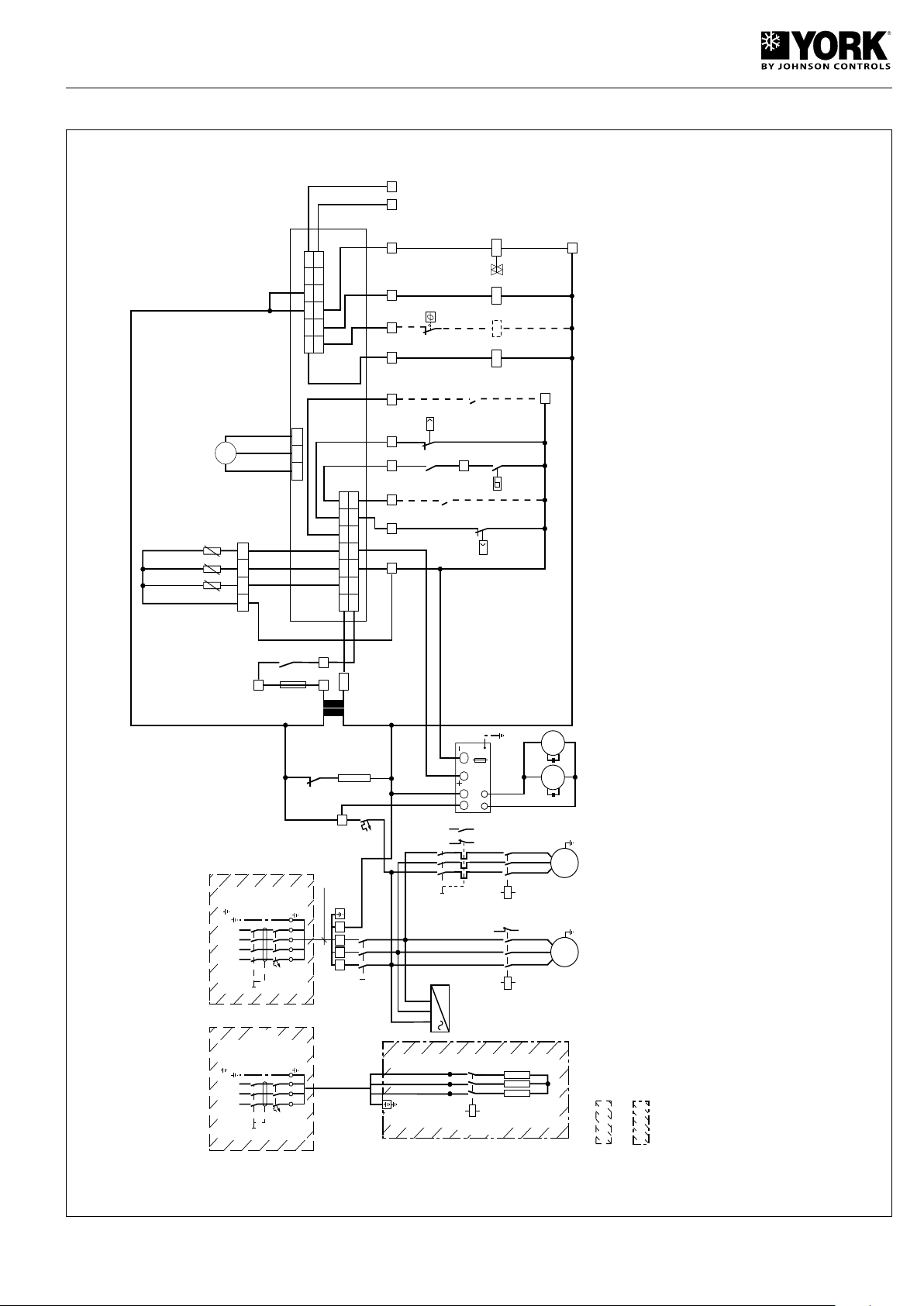
Wiring diagram, YLCA/YLHA PLUS 20 TC and T 400.3.50
I-2534g
YLCA/YLHA PLUS 20 TC and T
400.3.50
L1
L1
L2
Q1
400V, 3 ~,50Hz,
K2
(17)
AH
2
1
4
3
MS
1
F1
F1
GO
GND
D4 D2 D1 D3
D5
GND
N1 C
1
/2 C5
N2
C
1
/2 C
3
/4
N3 N4 N5
C
3
/
4
1 2 3 4 5 6
7 8 9 10 11 12
A1
A2
(2)
N1 N4N3 N5 C5
GO
G
B1
GND
B2
GND
B3
Y
ID5
GND
ID3
ID4
ID1
ID2
B1 B2 B3
B1 B2
GND
B4 V+GND
B4
J1
10 9 8
7 5 4 3
2 1
11121314
6
J2
4 5 6 7
8
9
10 11 12 13 14 15 16 17 18
L1
L3
L2 L3
L2 L3
5
6
A1
A2
M4
K3
(18)
A1
A2
3
~
M1
K1
(16)
A1
A2
(
5
)
3
~
(12)
Q4
3
4
A1
A2
(3)
1 2 30
C3
M3
C2
M2
19 20
EXTERIOR
OUTSIDE
B3
L1 L2 L3 N
L1
L1
N
N
Q2
25A
400V, 3 ~,50Hz,N,
L2 L3
L2 L3
LOS COMPONENTES INCLUIDOS EN ESTOS RECUADROS SON
ACCESORIOS STANDARD SUMINISTRADOS POR EL FABRICANTE
LOS COMPONENTES INCLUIDOS EN ESTOS RECUADROS NO SON
SUMINISTRADOS POR EL FABRICANTE
THE COMPONENTS INCLUDED IN THESE BOXES ARE NOT SUPPLIED
BY THE MANUFACTURER.
THE COMPONENTS INCLUDED IN THESE BOXES ARE STANDARD
ACCESSORIES SUPPLIED BY THE MANUFACTURER.
1.- ALARMA. CONTACTO NORMALMENTE ABIERTO LIBRE DE TENSIÓN
(3A.RESISTIVOS MÁXIMO)
ALARM.CONTACT NORMALLY OPEN, VOLT-FREE (3A. MAXIMUM RESISTANCE.)
2.-
SOLO UNIDADES TC
TC UNITS ONLY
NOTAS:
NOTES:
C2, C3 CONDENSADOR VENTILADOR
FAN CONDENSER
CH RESISTENCIA CARTER COMPRESOR
COMPRESSOR SUMP HEATER
F1 FUSIBLE PROTECCIÓN CONTROL
ELECTRONICO / MANIOBRA 24V
24V ELECTRONIC CONTROL FUSE
F2 FUSIBLE PROTECCIÓN VARIADOR DE
VELOCIDAD VENTILADOR
FAN SPEED CONTROLLER FUSE
FC CONTROL DE FASES
PHASE CONTROL
FS CONTROL CAUDAL DE AGUA (UNIDADES TC)
WATER FLOW SWITCH (TC UNITS)
FSC VARIADOR VELOCIDAD VENTILADOR
FAN SPEED CONTROLLER
HP PRESOSTATO ALTA 41 BAR
HIGH PRESSURE SWITCH, 41 BAR
HTP PROTECTOR TÉRMICO RESISTENCIA
HEATER THERMAL PROTECTION
K1 CONTACTOR COMPRESOR
COMPRESSOR CONTACTOR
K2 CONTACTOR RESISTENCIA AUXILIAR
AUXILIARY HEATER CONTACTOR
K3 CONTACTOR BOMBA (UNIDADES TC)
PUMP CONTACTOR (TC UNITS)
LAK ACCESORIO LOW AMBIENT
KIT PRESOSTATICO
LOW AMBIENT KIT, ACCESSORY
LP PRESOSTATO BAJA 2,5 BAR
LOW PRESSURE SWITCH, 2.5BAR
M1 COMPRESOR
COMPRESSOR
M2 VENTILADOR 1
FAN 1
M3 VENTILADOR 2
FAN 2
M4 BOMBA (UNIDADES TC)
PUMP (TC UNITS)
MS INTERRUPTOR GENERAL
MAIN SWITCH
Q1 PROTECTOR MAGNETOTÉRMICO
RESISTENCIA APOYO
BACKUP HEATER MAGNETO THERMAL
PROTECTOR
Q2 PROTECTOR MAGNETOTÉRMICO GENERAL /
COMPRESOR
MAIN MAGNETO THERMAL PROTECTOR,
COMPRESSOR
Q3 PROTECTOR MAGNETOTÉRMICO MANIOBRA
GENERAL 230V / VENTILADOR / BOMBA /
RESISTENCIA CARTER
MAIN OPERATING MAGNETO THERMAL
PROTECTOR, 220V/FAN/PUMP.
S UMP HEATER
Q4 PROTECTOR MAGNETOTÉRMICO BOMBA
(UNIDADES TC)
PUMP MAGNETO THERMAL PROTECTOR
(TC UNITS)
R00 SELECTOR REMOTO PARO / MARCHA
ON/OFF REMOTE CONTROL
RCH SELECTOR REMOTO FRIO / CALOR
COOL/HEAT REMOTE CONTROL
T TRANSFORMADOR 230 / 24V 20VA
230 / 24V 20VA TRANSFORMER
V4V VALVULA DE 4 VIAS
4-WAY VALVE
COMPRESOR
COMPRESSOR
RESISTENCIA AUXILIAR
AUXILIARY HEATER
VALVULA DE 4 VIAS
4-WAY VALVE
BOMBA
PUMP
(NOTA 1)
(NOTE 1)
VERDE
GREEN
BLANCO
WHITE
NEGRO
BLACK
ENTRADA AGUA
WATER INTAKE
SALIDA AGUA
WATER OUTLET
F1
315 mA
(LENTO)
(SLOW)
(0)
N2
HTP
Q3
4A
FSC
LOAD
F2
L N Y
GND
T
230V
0V
20 VA
CH
21
22
K1
FS
P
HP
41
bar
R00
RCH
K1
V4V
2
chiller
2
21
22
1
2
3
4
5
6
1
2
3
4
5
6
1
2
3
4
5
6
6
2
4
13
14
21
22
FC
(8)
L1
L3
L2
(16)
14
11
FC
(1)
13
14
Q4
(3)
K3
A
24
4 mm
2
Cu
P
LP
2,5
bar
A CONTROL ELECTRÓNICO
ELECTRONIC CONTROL
AH RESISTENCIA AUXILIAR
AUXILIARY HEATER
B1 SONDA TEMPERATURA ENTRADA AGUA (NTC)
WATER INTAKE TEMPERATURE PROBE (NTC)
B2 SONDA TEMPERATURA SALIDA AGUA (NTC)
WATER OUTLET TEMPERATURE PROBE (NTC)
B3 SONDA TEMPERATURA EXTERIOR (NTC)
OUTSIDE TEMPERATURE PROBE (NTC)
B4 SONDA DE PRESIÓN RACIOMÉTRICA
CONTROL VELOCIDAD VENTILADORES/
DESESCARCHES
RATIOMETRIC PRESSURE PROBE FAN SPEED
CONTROL DEFROSTS (ACCESSORY)
(SOLO YLHA)
(YLHA ONLY)
INSTALAR
EN OBRA
INSTALL
AT JOB
SITE
K2
33
Page 34
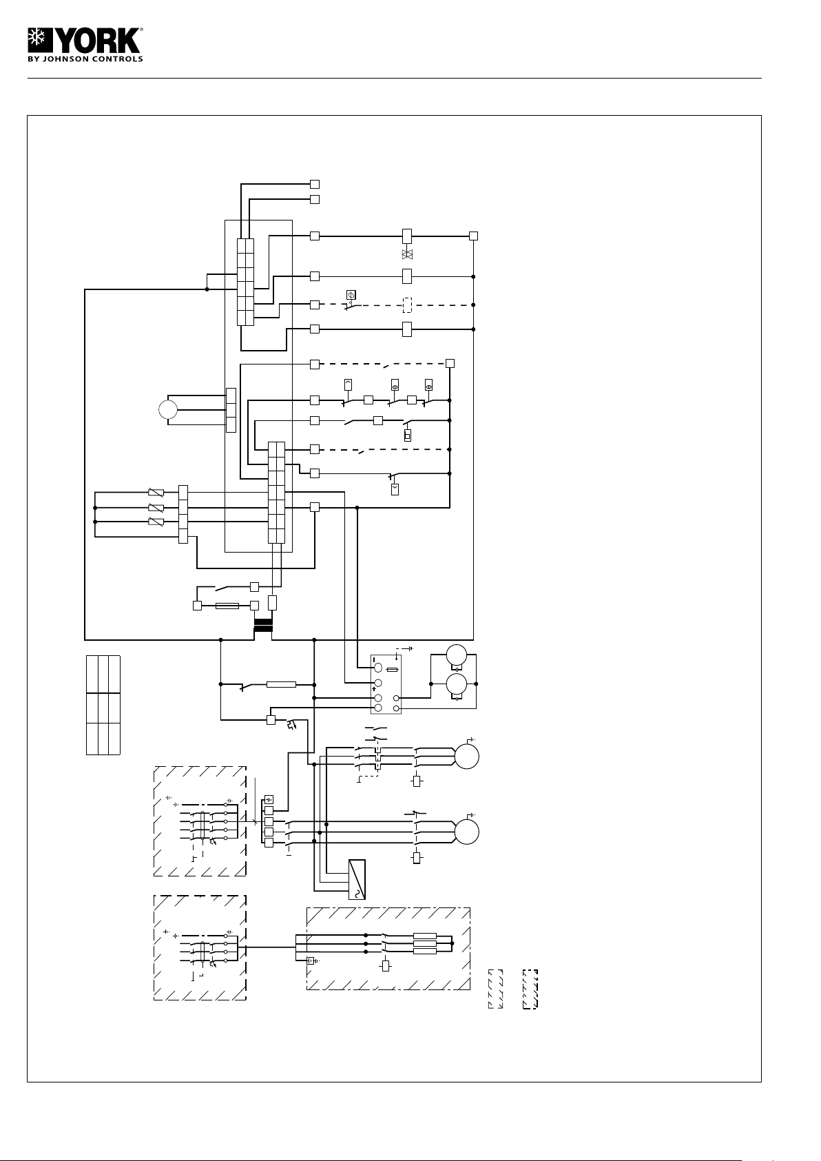
Wiring diagram, YLCA 27 TC, YLHA PLUS 27 TC, 400.3.50
I-2565e
YLCA 27 TC
YLHA PLUS 27
400.3.50
"B" mm Cu
2
L1
L1
L2
Q1
400V, 3 ~,50Hz,
K2
(17)
AH
2
1
4
3
MS
1
F1
F1
GO
GND
D4 D2 D1 D3
P
LP
2,5
bar
D5
GND
N1 C
1
/
2
C5
N2
C
1
/
2
C
3
/
4
N3 N4 N5
C
3
/
4
1 2 3 4 5 6
7 8 9 10 11 12
A1
A2
(2)
N1 N4N3 N5 C5
GO
G
B1
GND
B2
GND
B3
Y
ID5
GND
ID3
ID4
ID1
ID2
B1 B2 B3
B1 B2
GND
B4 V+GND
B4
J1
10 9 8
7 5 4 3
2 1
11121314
6
J2
4 5 6 7
8
9
10 11 12 13 14 15 16 17 18
L1
L3
L2 L3
L2 L3
5
6
A1
A2
M4
K3
(18)
A1
A2
3
~
M1
K1
(16)
A1
A2
(
5
)
3
~
(12)
Q4
3
4
A1
A2
(3)
1 2 30
C3
M3
C2
M2
19 20
B3
5
6
LOS COMPONENTES INCLUIDOS EN ESTOS RECUADROS SON
ACCESORIOS STANDARD SUMINISTRADOS POR EL FABRICANTE
LOS COMPONENTES INCLUIDOS EN ESTOS RECUADROS NO SON
SUMINISTRADOS POR EL FABRICANTE
THE COMPONENTS INCLUDED IN THESE BOXES ARE NOT SUPPLIED
BY THE MANUFACTURER.
THE COMPONENTS INCLUDED IN THESE BOXES ARE STANDARD
ACCESSORIES SUPPLIED BY THE MANUFACTURER.
1.- ALARMA. CONTACTO NORMALMENTE ABIERTO LIBRE DE TENSIÓN
(3A.RESISTIVOS MÁXIMO)
ALARM.CONTACT NORMALLY OPEN, VOLT-FREE (3A. MAXIMUM RESISTANCE.)
2.-
SOLO UNIDADES TC
TC UNITS ONLY
NOTAS:
NOTES:
COMPRESOR
COMPRESSOR
RESISTENCIA AUXILIAR
AUXILIARY HEATER
VALVULA DE 4 VIAS
4-WAY VALVE
BOMBA
PUMP
(NOTA 1)
(NOTE 1)
VERDE
GREEN
BLANCO
WHITE
NEGRO
BLACK
EXTERIOR
OUTSIDE
ENTRADA AGUA
WATER INTAKE
SALIDA AGUA
WATER OUTLET
F1
315 mA
(LENTO)
(SLOW)
(0)
N2
HTP
A CONTROL ELECTRÓNICO
ELECTRONIC CONTROL
AH RESISTENCIA AUXILIAR
AUXILIARY HEATER
B1 SONDA TEMPERATURA ENTRADA AGUA (NTC)
WATER INTAKE TEMPERATURE PROBE (NTC)
B2 SONDA TEMPERATURA SALIDA AGUA (NTC)
WATER OUTLET TEMPERATURE PROBE (NTC)
B3 SONDA TEMPERATURA EXTERIOR (NTC)
OUTSIDE TEMPERATURE PROBE (NTC)
B4 SONDA DE PRESIÓN RACIOMÉTRICA
CONTROL VELOCIDAD VENTILADORES/
DESESCARCHES
RATIOMETRIC PRESSURE PROBE FAN SPEED
CONTROL DEFROSTS (ACCESSORY)
C2, C3 CONDENSADOR VENTILADOR
FAN CONDENSER
CH RESISTENCIA CARTER COMPRESOR
COMPRESSOR SUMP HEATER
F1 FUSIBLE PROTECCIÓN CONTROL
ELECTRONICO / MANIOBRA 24V
24V ELECTRONIC CONTROL FUSE
F2 FUSIBLE PROTECCIÓN VARIADOR DE
VELOCIDAD VENTILADOR
FAN SPEED CONTROLLER FUSE
FC CONTROL DE FASES
PHASE CONTROL
FS CONTROL CAUDAL DE AGUA (UNIDADES TC)
WATER FLOW SWITCH (TC UNITS)
FSC VARIADOR VELOCIDAD VENTILADOR
FAN SPEED CONTROLLER
HP PRESOSTATO ALTA 41 BAR
HIGH PRESSURE SWITCH, 41 BAR
HTP PROTECTOR TÉRMICO RESISTENCIA
HEATER THERMAL PROTECTION
K1 CONTACTOR COMPRESOR
COMPRESSOR CONTACTOR
K2 CONTACTOR RESISTENCIA AUXILIAR
AUXILIARY HEATER CONTACTOR
K3 CONTACTOR BOMBA (UNIDADES TC)
PUMP CONTACTOR (TC UNITS)
LAK ACCESORIO LOW AMBIENT
KIT PRESOSTATICO
LOW AMBIENT KIT, ACCESSORY
LP PRESOSTATO BAJA 2,5 BAR
LOW PRESSURE SWITCH, 2.5 BAR
M1 COMPRESOR
COMPRESSOR
M2 VENTILADOR 1
FAN 1
M3 VENTILADOR 2
FAN 2
M4 BOMBA (UNIDADES TC)
PUMP (TC UNITS)
MS INTERRUPTOR GENERAL
MAIN SWITCH
PTV1 /PTV2 PROTECTOR TÉRMICO VENTILADOR
FAN HEAT SWITCH
Q1 PROTECTOR MAGNETOTÉRMICO
RESISTENCIA APOYO
BACKUP HEATER MAGNETO THERMAL
PROTECTOR
Q2 PROTECTOR MAGNETOTÉRMICO
GENERAL COMPRESOR
MAIN MAGNETO THERMAL PROTECTOR,
COMPRESSOR
Q3 PROTECTOR MAGNETOTÉRMICO
MANIOBRA GENERAL 230V / VENTILADOR /
BOMBA / RESISTENCIA CARTER
MAIN MAGNETO THERMAL
PROTECTOR, 220V/FAN/PUMP.
SUMP HEATER
YLCA/YLHA 27 : 4A
YLCA/YLHA 40 : 6A
Q4 PROTECTOR MAGNETOTÉRMICO BOMBA
(UNIDADES TC)
UMP MAGNETO THERMAL
PROTECTOR (TC UNITS)
R00 SELECTOR REMOTO PARO / MARCHA
ON/OFF REMOTE CONTROL
RCH SELECTOR REMOTO FRIO / CALOR
COOL/HEAT REMOTE CONTROL
T TRANSFORMADOR 230 / 24V 20VA
230 / 24V 20VA TRANSFORMER
V4V VALVULA DE 4 VIAS
4-WAY VALVE
Q3
FSC
LOAD
F2
L N Y
GND
T
230V
0V
20 VA
CH
21
22
K1
FS
P
HP
41
bar
R00
RCH
K1
V4V
2
chiller
2
21
22
1
2
3
4
5
6
1
2
3
4
5
6
1
2
3
4
5
6
6
2
4
13
14
21
22
FC
(8)
L1
L3
L2
(16)
14
11
FC
(1)
13
14
Q4
(3)
K3
A
UNIDAD
Q2
"B" mm
2
Cu
24
40 40
10
27
32 6
L1 L2 L3 N
L1
L1
N
N
Q2
Amp
400V, 3 ~,50Hz,N,
L2 L3
L2 L3
PTV1
PTV2
SOLO (YLHA)
(YLHA ONLY)
INSTALAR
EN OBRA
INSTALL
AT JOB
SITE
K2
34
Page 35
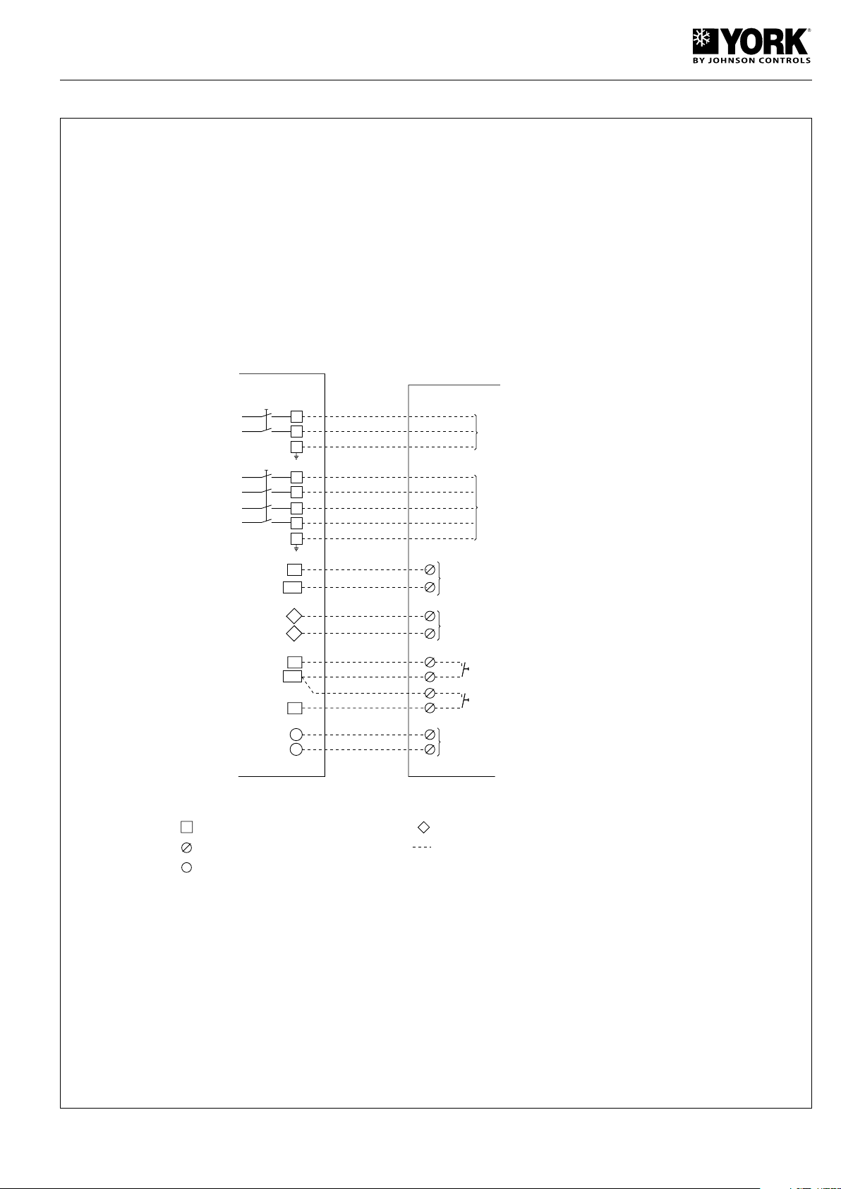
Wiring
L1
PE
L3
N
L2
POWER SUPPLY
400V - 3 + N - ph - 50Hz
2
N2
C
NO
REMOTE ON/OFFSWITCH
AUXILIARY
HEATER
YLCA/YLHA PLUS CONNECTING STRIP TERMINALS
OUTDOOR UNIT TERMINALS
YLCA/YLHA PLUS CONNECTING VOLT-FREE CONTACT
CLIENT'S WIRING
YLCA TERMINAL
CONNECTING STRIP
YLCA CONNECTING STRIP
TERMINALS
MAIN SWITCH
230 Vca terminal
N5
GENERAL ALARM (VOLT-FREE INVERTER CONTACT.
RESIST. 2A MAX. AT 230Vac).
D1
GND
FLOW SWITCH (ON UNITS WITHOUT HYDRO KIT).
ID5
REMOTE COOL/HEAT SWITCH
CLOSED=COOL. OPEN= HEAT
(YLHA PLUS ONLY)
C5
D2
L1
PE
N
POWER SUPPLY
230V - 1 + N - ph - 50Hz
GND
SINGLE -PHASE
UNITS
THREE-PHASE
UNITS
YLCA/YLHA PLUS 5 to 27
35
Page 36
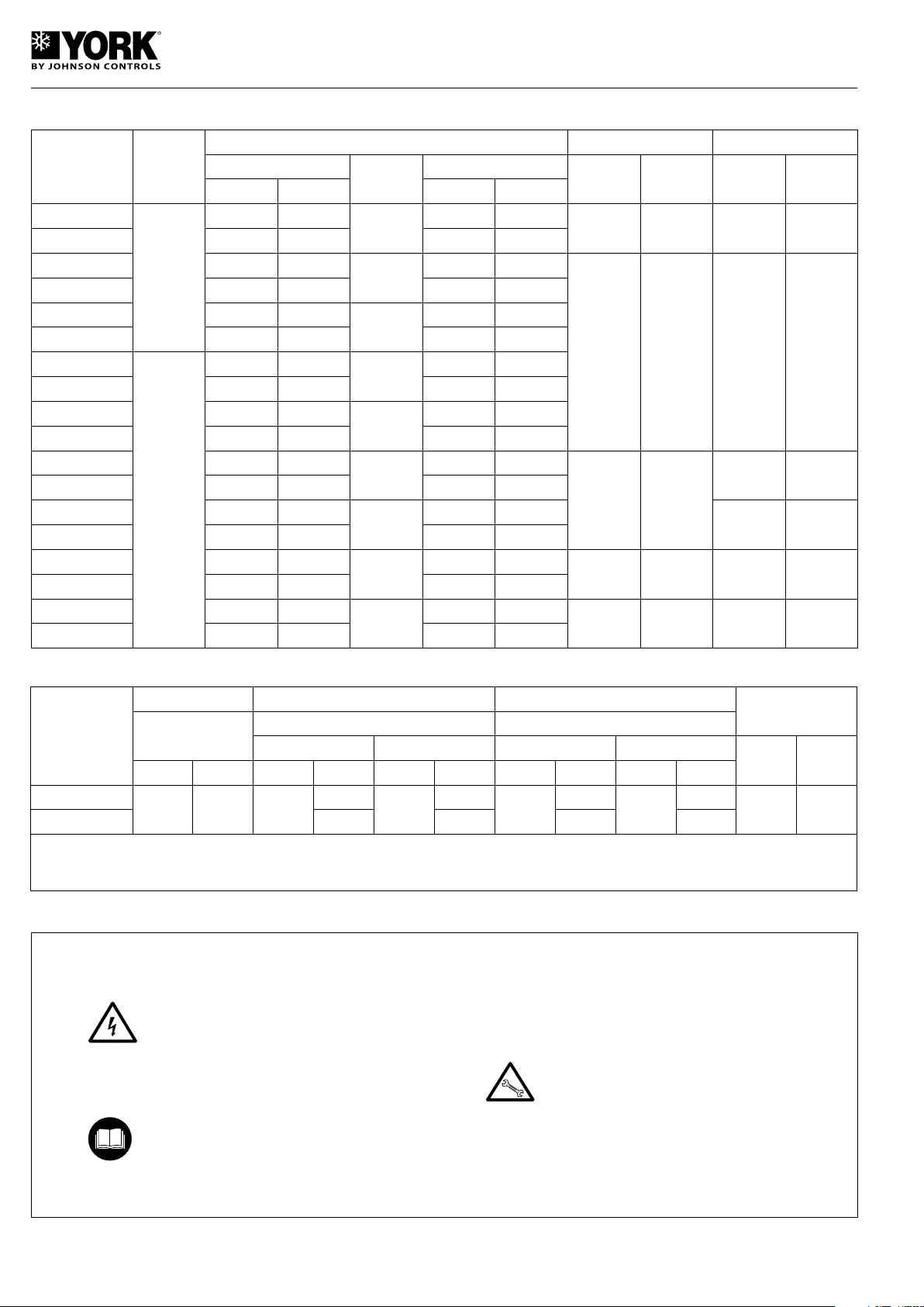
Electrical characteristics
Model
YLCA 5
YLHA PLUS 5
YLCA 7
YLHA PLUS 7
YLCA 9
YLHA PLUS 9
YLCA 7
YLHA PLUS 7
YLCA 9
YLHA PLUS 9
YLCA 12
YLHA PLUS 12
YLCA 15
YLHA PLUS 15
YLCA 20
YLHA PLUS 20
YLCA 27
YLHA PLUS 27
Power
supply
V.ph.Hz.
230.1.50
400.3.50
Compressor Fans Pump
Nominal A
Cool Heat Cool Heat
7.8 -
7.8 8.1 1.73 1.76
11.7 -
12.4 13.2 2.56 2.76
17 -
17 14.5 3.26 3.06
3.9 -
4.1 4.8 2.56 2.76
5.7 -
6 5.8 3.26 3.06
6.36 -
6.36 6.38 3.80 3.77
8.9 -
8.7 8.9 5.25 5.23
13 -
12.2 11.7 6.62 6.26
16.7 -
16.7 16 8.73 8.24
Start
A
60
82
97
35
48
51
74
95
118
Nominal kW
1.73 -
2.41 -
3.40 -
2.41 -
3.16 -
3.80 -
5.38 -
6.65 -
8.73 -
NominalANominalWNominalANominal
W
0.6 140 0.65 160
0.8 170 0.95 210
1.8 400
2 x 0.87 2 x 185
2.15 490
2 x 0.8 2 x 170 1.1 390
2 x 0.85 2 x 175 1.34 755
Limits of use
Voltage limits Entering air temperature to coil DB Water output temperature
Model
YLCA
YLHA PLUS
(1) At lower water temperatures, it is advisable to use glycol type antifreeze mixtures. Minimum Temperature with glycol -5° C. (2) -18°C with low tem
perature kit (optional) on models YLCA/YLHA PLUS 5 to 20, and standard on models YLCA/YLHA PLUS 20, 27. (3) 50°C if entering air temperature
is above 0°C.
Nominal 400
Minimum Maximum Cool Heat Cool Heat Cool Heat Cool Heat
342 436 -10 (2)
Minimum °C Maximum °C Minimum °C Maximum °C
Operating cycle Operating cycle
-
-10 20 30 50 (3)
46
5 (1)
15
-
Temperature dif.
between water
output and intake
Minimum °CMaximum
°C
3 7
Prior to final approval of the installation
Check:
- Voltage is always between 342 - 436 V.
- Power supply cable section is, at least, as
indicated on the corresponding wiring diagrams.
- The warrantee card has been filled out.
- Maintenance instructions have been given,
or a regular maintenance contract has
been signed.
- Operating instructions have been given to
the user.
-
36
Page 37

Operating instructions µC2
(Rev. 1016)
Control unit description
This is a multipurpose controller specially programmed for
use with air-water chillers and heat pumps equipped with a
compressor with one single power stage.
Main functions
- Water temperature control (at intake or outlet, as per parameter r6).
- Defrost cycle management.
- System operating and safety management.
- Fan speed control.
- Alarm management.
- Connection for supervision and telephone assistance (access serial connection RS485).
Devices controlled
- Compressor
- Fans
- Four-way valve
- Water pump
- Alarm device
- Auxiliary heater
Standard components
- Control module. This is the central nucleus that processes
the signals coming from the probes and protection elements
of the entire system to control its active elements: compressor and fans, four-way valve, water circulating pump, alarm
relay and auxiliary heater. Power supply 24 Vac.
Can also be used for access and control of the system by
means of the display, buttons and LEDs available. Allows
selection cool, heat and off functions. Operating parameters
can also be modified, and the system can be supervised
as well.
- Fan speed control module. Operates by phase cut-off.
Includes fuse.
- NTC and ratiometric (pressure) probes.
YLCA/YLHA PLUS 5 to 15 standard.
4 NTC probes are used to read system temperatures:
B1. Controls set point. Reads water temperature at ex-
changer intake.
B2. Antifreeze control. Reads water temperature at ex-
changer discharge.
B3. Fan speed and defrost cycle control. Reads refrigerant
temperature inside the coil.
B4. Dynamic set point control. Reads outdoor air tempera-
ture.
YLHA PLUS, YLCA 20, 27 and YLCA 5-15 LAK (low tem-
perature kit).
3 NTC probes are used to read system temperatures and
a ratiometric pressure transducer (B4) to read refrigerant
pressure inside the coil:
B1. Controls set point. Reads water temperature at ex-
changer intake.
B2. Antifreeze control. Reads water temperature at ex-
changer discharge.
B3. Controls dynamic set point. Reads outdoor air tempera-
ture.
B4. Fan speed and defrost cycle control. Reads refrigerant
pressure inside the coil.
Parameters
The set of parameters that configure the operating program of
the unit is divided into four levels (Factory, Super User, User
and Direct), depending upon the function of each parameter
and the user’s access level. The parameters of each level
can be modified from that same level, as well as lower level
parameters.
Factory level
Accessible with the Factory password. Allows configuration
of all unit parameters.
Super User level
Accessible with Super User password. Allows setting Super
User, User and Direct parameters.
User level
Accessible with password 22. Allows access to all parameters
the user normally sets.
Direct level
Accessible without a password. Allows reading the values
detected by the probes, as well as other system values. Can
be used by the user without affecting unit operation.
General
Modification of the parameters that affect basic unit configuration should be made with the controller in Standby position.
37
Page 38
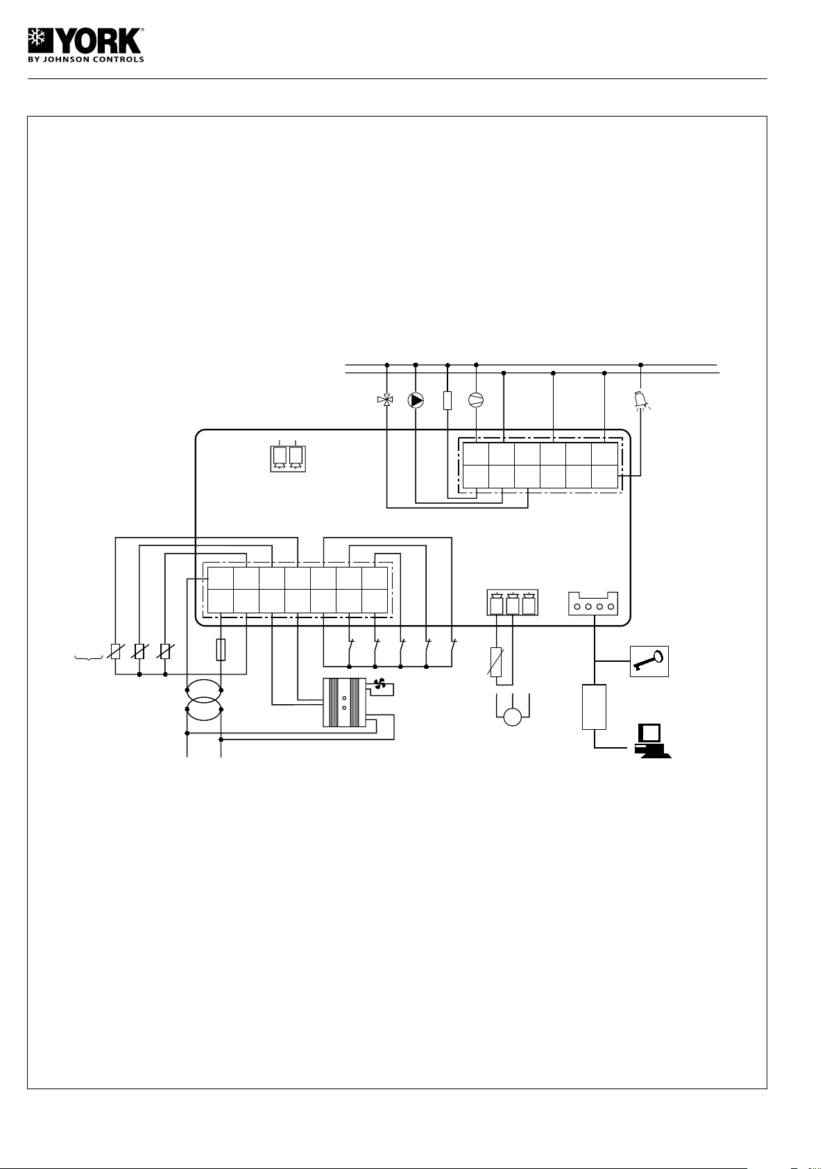
General diagram, YLCA 5, 7, 9, 12 and 15
P
G0GB1
GNDB2GNDB3Y
ID5
GND
ID3
ID4
ID1
ID2
B1: WATER INTAKE TEMPERATURE PROBE (SET POINT CONTROL)
B2: WATER DISCHARGE TEMPERATURE PROBE (ANTIFREEZE PROTECTION)
B3: COIL TEMPERATURE PROBE (FAN SPEED AND DEFROST CONTROL)
B4: OUTDOOR TEMPERATURE PROBE (DYNAMIC SET POINT)
ID1: WATER FLOW SWITCH
ID2: REMOTE COOL/HEAT
ID3: HIGH PRESSURE SWITCH
ID4: LOW PRESSURE SWITCH
ID5: REMOTE ON/OFF
ID4
ID2
ID1
ID3
ID5
WATER DISCHARGE (B2)
WATER INTAKE (B1)
315
mA
24
TRANSFORMER
230
230.1.50
N
L
FAN SPEED
CONTROL
PROGRAMMABLE
KEY
COMMUNICATION
RS 485
No3
XXC5No1
No2
C1/2
No4
C3/4
No5
PUMP
4-WAY VALVE
230.1.50
ALARM
COMP. 1
N
L
C1/2 C3/4
HEATER
GNDB4V+
(B4)
LAK ACCESSORY
YLCA 5, 7, 9, 12 and 15
(see note 1)
OUTDOOR PROBE.
STANDARD UNIT
NOTE 1.- WHEN THE LOW AMBIENT KIT IS INSTALLED. THE B4 PROBE MUST BE CONFIGURED AS A PRESSURE TRANSDUCER. AND B3 AS
AN OUTDOOR TEMPERATURE NTC PROBE.
OUTDOOR PROBE ON UNITS WITH LAK
COIL PROBE ON STANDARD UNITS
B3
(B4)
38
Page 39
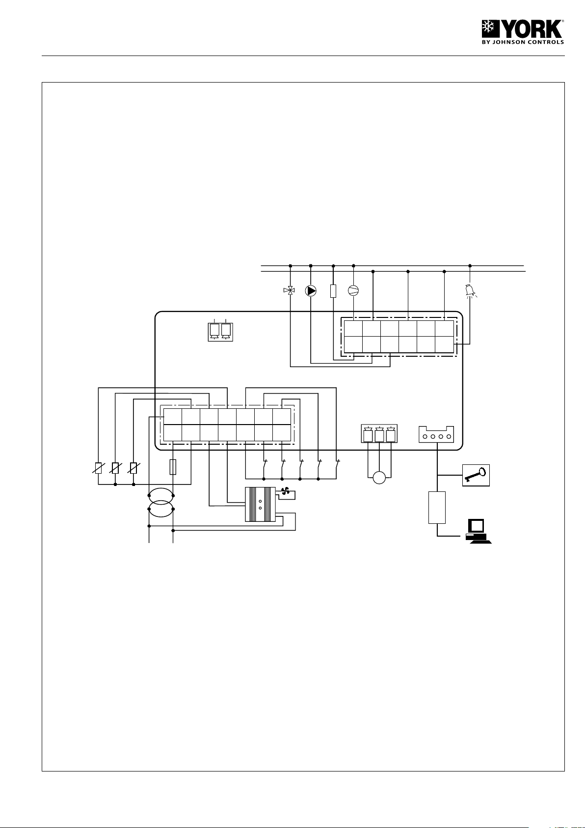
General diagram, YLCA 20,27 and YLHA PLUS 5-27
G0GB1
GNDB2GNDB3Y
ID5
GND
ID3
ID4
ID1
ID2
B1: WATER INTAKE TEMPERATURE PROBE (SET POINT CONTROL)
B2: WATER DISCHARGE TEMPERATURE PROBE (ANTIFREEZE PROTECTION)
B3: COIL TEMPERATURE PROBE FAN SPEED AND DEFROST CONTROL)
B4: OUTDOOR TEMPERATURE PROBE (DYNAMIC SET POINT)
ID1: WATER FLOW SWITCH
ID2: REMOTE COOL/HEAT
ID3: HIGH PRESSURE SWITCH
ID4: LOW PRESURE SWITCH
ID5: REMOTE ON/OFF
ID4
ID2
ID1
ID3
ID5
WATER DISCHARGE (B2)
WATER INTAKE (B1)
315
mA
24
TRANSFORMER
230
230.1.50
N
L
FAN SPEED
CONTROL
PROGRAMMABLE
KEY
COMMUNICATION
RS 485
No3
XXC5No1
No2
C1/2
No4
C3/4
No5
PUMP
4-WAY VALVE
230.1.50
ALARM
COMP. 1
N
L
C1/2 C3/4
HEATER
GNDB4V+
OUTDOOR PROBE (B3)
(B4)
P
PRESSURE PROBE
39
Page 40
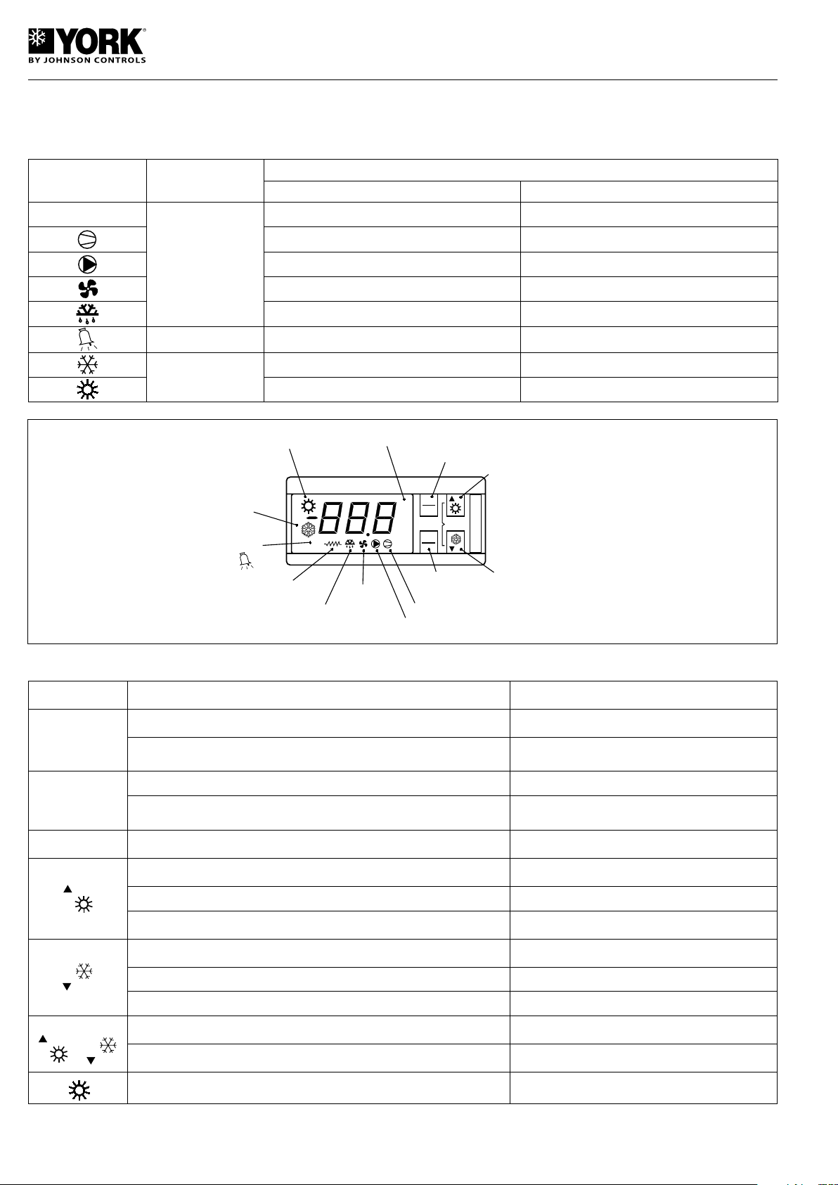
Symbols on the display
clear
mute
PRG
1
PROGRAM
HEAT INCREMENT/
SELECT
COMPRESSOR NUMBER
SEL
HEAT CYCLE
COOL CYCLE
ALARM
HEATER
(INOPERATIVE)
DEFROST
FAN
PUMP
COMPRESSORS
PARAMETERS/
VALUES SELECT
COOL DECREASE/
SELECT
The display has three figures in green, plus a symbol and a decimal. It also shows the symbols, in amber, of the functions
selected (the alarm symbol is red).
Symbol Colour
1
Amber
Red Alarm active -
Amber
Meaning
With LED on permanently With LED flashing
Compressor in operation Timing start-up
Compressors under call -
Water pump in operation -
Fans in operation -
Defrost active -
Cool cycle -
Heat cycle -
Functions of remote control unit buttons
BUTTON UNIT STATUS PRESSING
Loads values by default Applies voltage when pressed
Prg/mute
Sel
Prg+Sel
+
SEL +
Return to superior sub-group within programming area until output of same
(except changes in E2PROM)
Access to Direct parameters Press 5 seconds
Selects a Direct parameter and shows its value / Confirms parameter
changes
Programming parameters with password Press 5 seconds
Selects superior parameter within the programming area Simply press or continuous
Increase value Simply press or continuous
Selects heat function from standby position and vice-versa (P6=1) Press 5 seconds
Selects lower parameter within programming area Simply press or continuous
Lower value Simply press or continuous
Selects cool function from standby position and vice-versa (P6=1) Press 5 seconds
Manual alarm reset Press 5 seconds
Clears hour counters (within programming area) Press 5 seconds
Forced manual defrost Press 5 seconds
Simply press
Simply press
40
Page 41
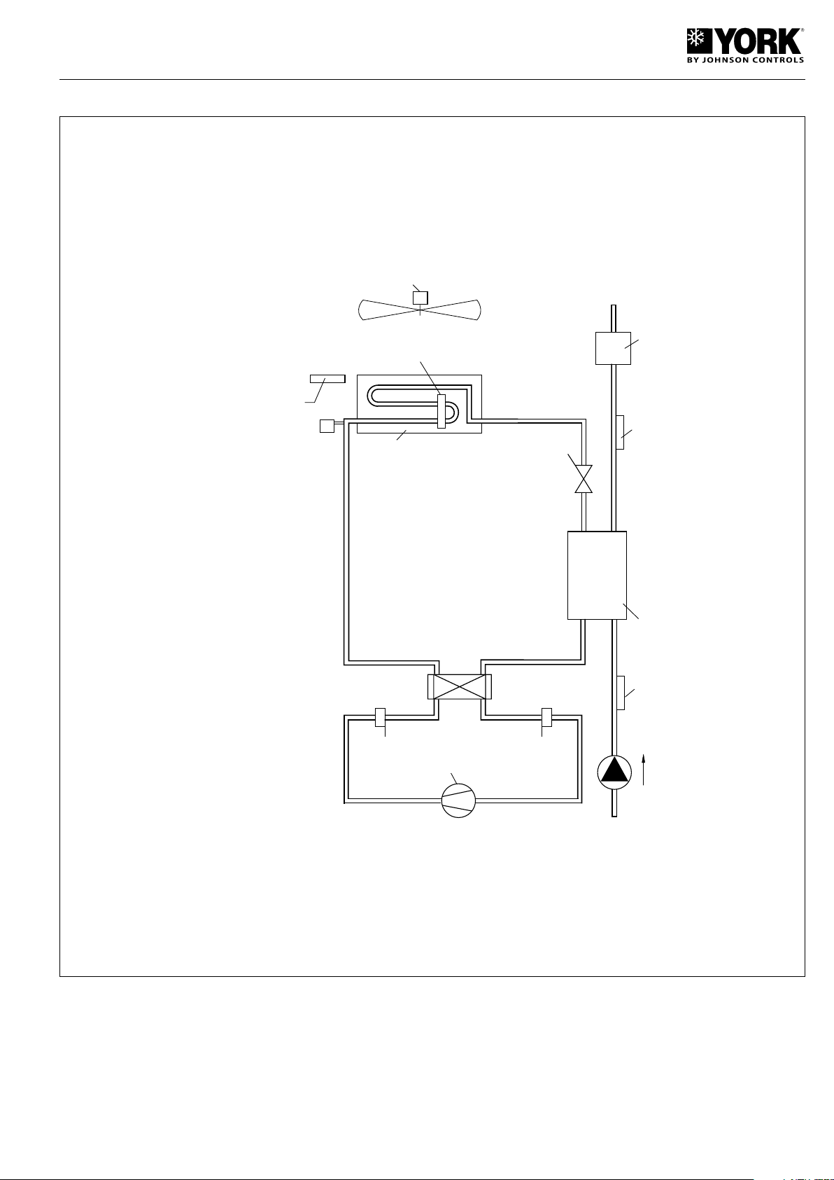
Location of controls
EXCHANGER OUTDOOR NTC PROBE
(YLCA/YLHA PLUS 5 to 15) (B3)
FAN
INDOOR EXCHANGER
4-WAY
VALVE
WATER
DISCHARGE
NTC PROBE
(B2)
FLOW
SWITCH
(FS)
PUMP
WATER INTAKE
NTC PROBE (B1)
INDOOR EXCHANGER
HIGH PRESSURE
SWITCH (HP)
LOW PRESSURE
SWITCH (LP)
COMPRESSOR
PRESSURE
PROBE (BA)
(YLCA/YLHA PLUS
5 to 20 LAK;
YLCA/YLHA PLUS
20 to 27)
OUTDOOR TEMPERATURE PROBE
YLCA/YLHA PLUS 5 to 15 WITH LAK (B3)
YLCA/YLHA PLUS 5 to 15 STANDARD (B4)
YLCA/YLHA PLUS 20 to 27 STANDARD (B3)
Parameter tables
The following tables show the parameters and their values
divided into groups.
Parameter level codes
D = Direct
U = User
S = Super User
F = Factory
Variables for supervision (VS)
R/W = Read/write parameter
R = Read only parameter
41
Page 42
Parameters related to the probes
Display Description Level VS Unit Max. Min. Value
NTC B1 probe (water intake); 0=absent (function not available).
/01
1=present
NTC B2 probe (water outlet). 0=absent (function not available).
/02
1=present
/03
NTC B3 probe . 1=condensation probe. 2=outdoor probe. F 14 (R/W) - 1 0
Probe type B4. 0=absent. 1=ON/OFF. 2=outdoor NTC probe. 3=ratio-
/04
metric 5Vdc.
Minimum input voltage
/09
Maximum input voltage
/10
Minimum pressure
/11
Maximum pressure
/12
Calibration probe B1
/13
Calibration probe B2
/14
Calibration probe B3
/15
Calibration probe B4
/16
Digital filter
/21
Input limitation
/22
Measuring unit 0 = C; 1 = 1F
/23
b00
b01
b02
b03
b04
(a) YLCA/YLHA PLUS 5 to 15 /03=1; YLCA/YLHA PLUS 5 to 15 LAK 03/=2; YLCA/YLHA PLUS 20 to 27 03/=2.
(b) YLCA/YLHA PLUS 5 to 15 /04=2; YLCA/YLHA PLUS 5 to 15 LAK 04/=3. YLCA/YLHA PLUS 20 to 27 04/=3.
Probe viewed on display
Value read by probe B1
Value read by probe B2
Value read by probe B3
Value read by probe B4
F 1 (R/W) - 1 0
F 2 (R/W) - 1 0
F 15 (R/W) - 3 0
F 18 (R/W) 0.01 Vdc /10 0
F 19 (R/W) 0.01 Vdc 500 /09
F 1 (R/W) bar /12 0
F 2 (R/W) bar 99.9 /11
F 3 (R/W) °C 12 -12
F 4 (R/W) °C 12 -12
F 5 (R/W) °C 12 -12
F 6 (R/W) bar 12 -12
U 20 (R/W) - 15 1
U 21 (R/W) - 15 1
U 5 (R/W) - 1 0
U 24 (R/W) - 7 0
D 70 (R) °C - -
D 71 (R) °C - -
D 72 (R) °C - -
D 73 (R) °C/bar - -
1
1
(a)
(b)
50
450
0
45
0
0
0
0
4
8
0
0
-
-
-
-
Parameters related to the probes
Display Description Level VS Unit Max Min Value
c01
Minimum operating time U 25 (R/W) Sec. 999 0
c02
Minimum OFF time U 26 (R/W) Sec. 999 0
c03
Time between start-ups of the same compressor U 27 (R/W) Sec. 999 0
c06
Start-up timed U 30 (R/W) Sec. 999 0
c07
Compressor start-up delay with regard to the pump U 31 (R/W) Sec. 150 0
c08
Pump OFF delay with regard to the compressor U 32 (R/W) Min. 150 0
c10
Operating hour counter compressor D 90 (R) Hours 800 0 -
c14
Operating hour counter for compressor maintenance U 34 (R/W) Hours 100 0
c15
Operating hour counter for pump D 94 (R/W) Hours 800 0 -
c17
Minimum time between pump start-ups U 35 (R/W) Min. 150 0
c18
Minimum operating time for pump U 36 (R/W) Min. 15 0
60
60
300
10
20
1
0
5
1
42
Page 43
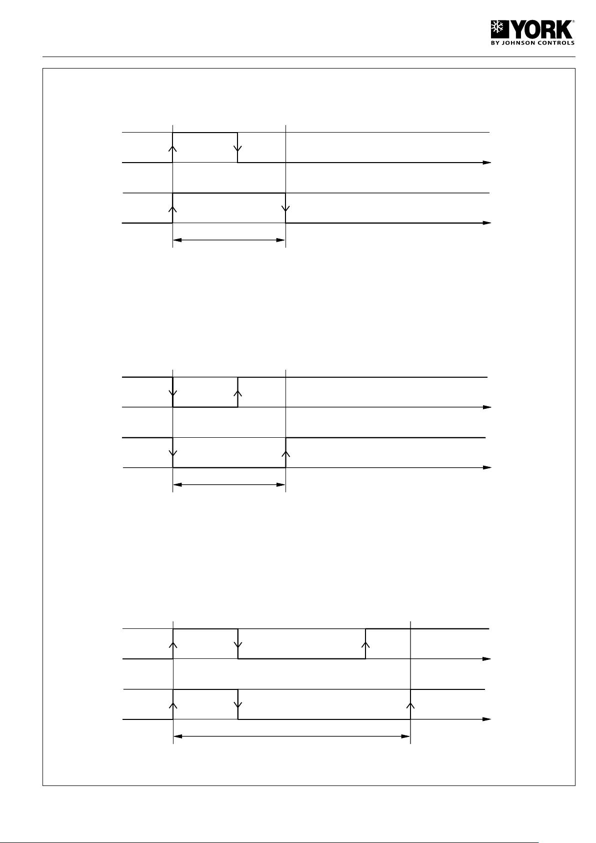
Minimum operating time of a compressor
ON
C1
SIGNAL
COMPRESSOR
ON
OFF
OFF
t
t
ON
C2
SIGNAL
COMPRESSOR
ON
OFF
OFF
t
t
ON
C3
SIGNAL
COMPRESSOR
ON
OFF
OFF
t
t
Minimum OFF time of a compressor
Minimum time between compressor start-ups
43
Page 44
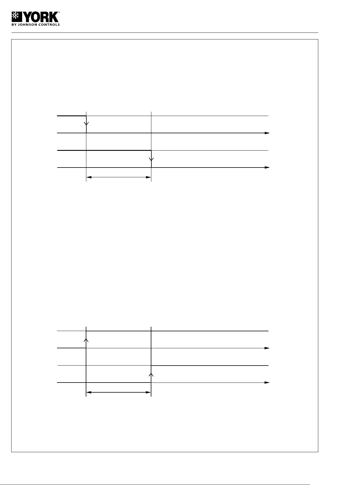
Compressor/pump OFF delays
ON
C8
PUMP
COMPRESSOR
ON
OFF
OFF
t
t
PUMP
COMPRESSOR
ON
C7
ON
OFF
OFF
t
t
Pump/compressor start-up delays
44
Page 45
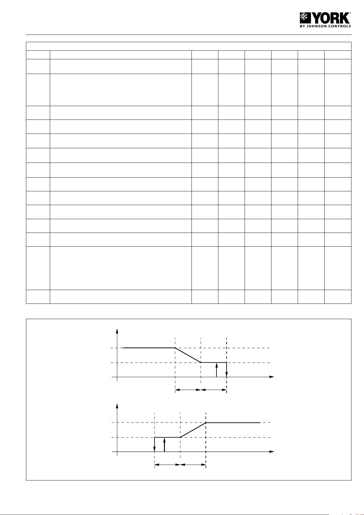
Parameters related to the fans
FAN SPEED
F9
CONDENSING
TEMPERATURE
F8
F10
F4
F3
FAN SPEED
F7
EVAPORATION
TEMPERATURE
F5
F6
F4
F3
Display Description Level VS Unit Max. Min. Value
F01
Fan outlet. 0=absent (function not available);
1=present
F 10 (R/W) 1 0
1
Operating mode:
0 = always ON (function not available)
F02
1 = Parallel with compressor (function not available)
U 48 (R/W) 3 0
3
2 = ON/OFF operation (function not available)
3 = Parallel with compressor and speed adjustment.
F03
F04
F05
F06
F07
F08
F09
F10
F11
F12
F13
Minimum triac voltage F 49 (R/W) step F04 0
Maximum triac voltage F 50 (R/W) step 100 F03
Cold cycle minimum speed temperature
Cool cycle minimum speed pressure (1)
Cool cycle maximum speed temp. differential
Cool cycle maximum speed pressure differential (1)
Diferencial temperatura paro del ventilador ciclo frío
Diferencial presión paro del ventilador ciclo frío (1)
F 24 (R/W)
F 26 (R/W)
F 28 (R/W)
°C
bar
°C
bar
°C
bar
80 -40
50 0
50 0
Cool cycle fan OFF differential F 30 (R/W) °C 80 -40
Heat cycle minimum speed temperature F 32 (R/W) °C 50 0
Heat cycle maximum speed differential F 34 (R/W) °C F08 0
Fan start-up time F 51 (R/W) sec. 120 0
Triac impulse duration F 52 (R/W) sec. 10 0
Fan management in defrost mode.
0 = fan deactivated
1 = fan activated in cool cycle mode (function not available)
F 53 (R/W) 2 0
2 = fan deactivated until defrost end temperature is reached and
start-up at maximum speed for d16
50
75
38
22.2
7
3.7
13
6.5
6
3
6
10
2
2
F14
Fan operative at start up with high ambient temperature U 91 (R/W) sec. 999 0
30
(1) Parameters to be checked when pressure probes are to be used (low ambient kit accessory) YLCA 5 to 15.
45
Page 46
Parameters related to defrost
DEFROST START
END DEFROST
(d06) MAXIMUM
DURATION DEFROST
TIMING START
(d05) MINIMUM TIME
DEFROST START
(d04) DEFROST END
TEMPERATURE
(d03) DEFROST START
TEMPERATURE
t
Display Description Level VS Unit Max. Min. Value
Execution of defrost 0= no (function not available)
d01
1= yes.
U 7 (R/W) - 1 0
1
Time or temperature defrost.
d02
0= time (function not available).
U 8 (R/W) - 1 0
1
1= temperature / pressure
d03
Defrost start temperature / pressure U 19 (R/W)
d04
Defrost end temperature / pressure U 21 (R/W)
d05
Minimum time for defrost start U 37 (R/W) sec. 150 10
d06
Minimum defrost duration U 38 (R/W) sec. 150 0
d07
Maximum defrost duration U 39 (R/W) Min. 15 1
d08
Time between two defrost cycles U 40 (R/W) Min. 150 10
°C
bar
°C
bar
Activation heaters in defrost
d11
0= no.
U 9 (R/W) - 0 1
1= yes.
d12
Compressor OFF before defrost F 43 (R/W) Min. 3 0
d13
Compressor OFF after defrost F 44 (R/W) Min. 3 0
Time of forced vent after defrost
d16
(only if F13=2).
F 47 (R/W) sec. 360 0
d04
80/
12
-40/
11
d03
-3
6.2
20
14.4
10
0
6
30
1
1
1
60
46
Page 47
Parameters related to defrost control configuration
Defrost reset
differential (A2)
A4
Defrost heater activation
differential (A5)
Heaters
Antifreeze alarm
A1 t
Antifreeze set point
temperature (A1)
Antifreeze heater
activation temperature
(A4)
Display Description Level VS Unit Max. Min. Value
A01
A02
A03
A04
A05
A06
A07
A08
A09
A10
Antifreeze control set point temperature U 11 (R/W) °C - A07
Antifreeze reset differential U 12 (R/W) °K 50 0.3
Antifreeze alarm bypass time U 22 (R/W) sec. 150 0
Antifreeze heater activation temperature U 13 (R/W) °C r16 A01
Antifreeze heater activation differential U 14 (R/W) °K 50 0.3
Backup heater control probe
0= control probe
F 6 (R/W) - 1 0
1= antifreeze probe
Minimum level antifreeze control set point temperature U 15 (R/W) °C 79 -40
Heating heater activation set point temperature U 16 (R/W) °C r15 A01
Heating heater deactivation set point temperature differential U 17 (R/W) °C 50 0.3
Automatic start-up by antifreeze alarm (Unit Standby)
0= function deactivated
1= Water pump + heater
U 23 (R/W) 3 0
2= Water pump + heater + compressor (heat pumps only)
3= Heater
3
5
0
3
2
0
3
3
3
2
47
Page 48
Parameters for unit configuration
Display Description Level VS Unit Max. Min. Value
H01
H02
H03
H04
H05
H06
H07
Unit model. 2= air-water intake;
3= air-water heat pump.
F 54 (R/W)
Number of vent circuits (do not modify this parameter) F 12 (R/W)
No. of evaporating units present (do not modify this parameter) F 13 (R/W)
No. of compressors per circuit (do not modify this parameter) F 55 (R/W)
Pump operation
0 = absent
1 = Always ON
F 56 (R/W) 3 0
2 = ON upon regulator call
3 = On under regulator and time call
COOL/HEAT digital intake
0= Absent. 1= Present
ON/OFF digital intake
0= Absent. 1= Present
U 14 (R/W) 1 0
U 15 (R/W) 1 0
2 (YLCA)
3 (YLHA
PLUS)
0
0
0
1
0
0
H08
H09
H10
H11
H12
H21
H22
Network configuration (do not modify this parameter) F 57 (R/W) 3 0
Keyboard locked
0= Disabled. 1= Abled
Serial direction for supervision
0= Future use as terminal
U 16 (R/W) 1 0
U 58 (R/W) 200 1
Output configuration (not selectable) F 59 (R/W) 3 0
4-way valve logic operation. Activated in cold cycle
(do not modify this parameter)
F 60 (R/W) 3 0
Second pump operation (do not modify this parameter) F 62 (R/W) 4 0
Default loading of parameters disabled
1= Disabled. 0= Abled
F 18 (R/W) 1 0
0
1
1
0
0
0
1
48
H23
Modbus protocol setting
0= Disabled. 1= Abled
F 11 1 0
0
Page 49
Parameters for alarm configuration
Display Description Level VS Unit Max. Min. Value
P01
P02
P03
P05
P06
P08
P09
P15
Alarm delay by flow switch at start-up. U 63 (R/W) sec. 150 0
Alarm delay by flow switch with unit in operation.
Alarm delay by low pressure switch at start-up. U 65 (R/W) sec. 200 0
Alarm reset
6= Low and high pressure switch manual reset at third
activation in one hour. Antifreeze control is manual reset.
Cool and heat cycle symbol.
1= "Sun" heat cycle. "Snow flake" cool cycle.
0= "Sun" cool cycle. "Snow flake" heat cycle.
Digital intake 1 for the flow switch.
Do not modify this parameter.
Digital intake 2 for remote setting Cool/Heat.
Do not modify this parameter.
Low pressure alarm selection.
0= Inoperative with compressor OFF.
1= Operative with compressor OFF.
U 64 (R/W) sec. 120 0
F 67 (R/W)
F 19 (R/W) 1 0
F 69 (R/W)
F 70 (R/W)
F 76 (R/W) 1 0
20
5
60
6
1
1
9
1
P16
P17
P18
P19
P20
High water temperature alarm of return water. U 38 (R/W) °C 80 -40
High temperature delay at start-up. U 77 (R/W) sec. 250 0
High pressure alarm by transducer
0= Function disabled.
Low temperature alarm of return water. U 40 (R/W) °C 80 -40
Alarm activation by high or low water temperature at
start-up.
1= Function abled.
0= Function disabled.
F 39 (R/W) bar 99.9 0.1
U 20 (R/W) 1 0
30
30
41
10
0
49
Page 50
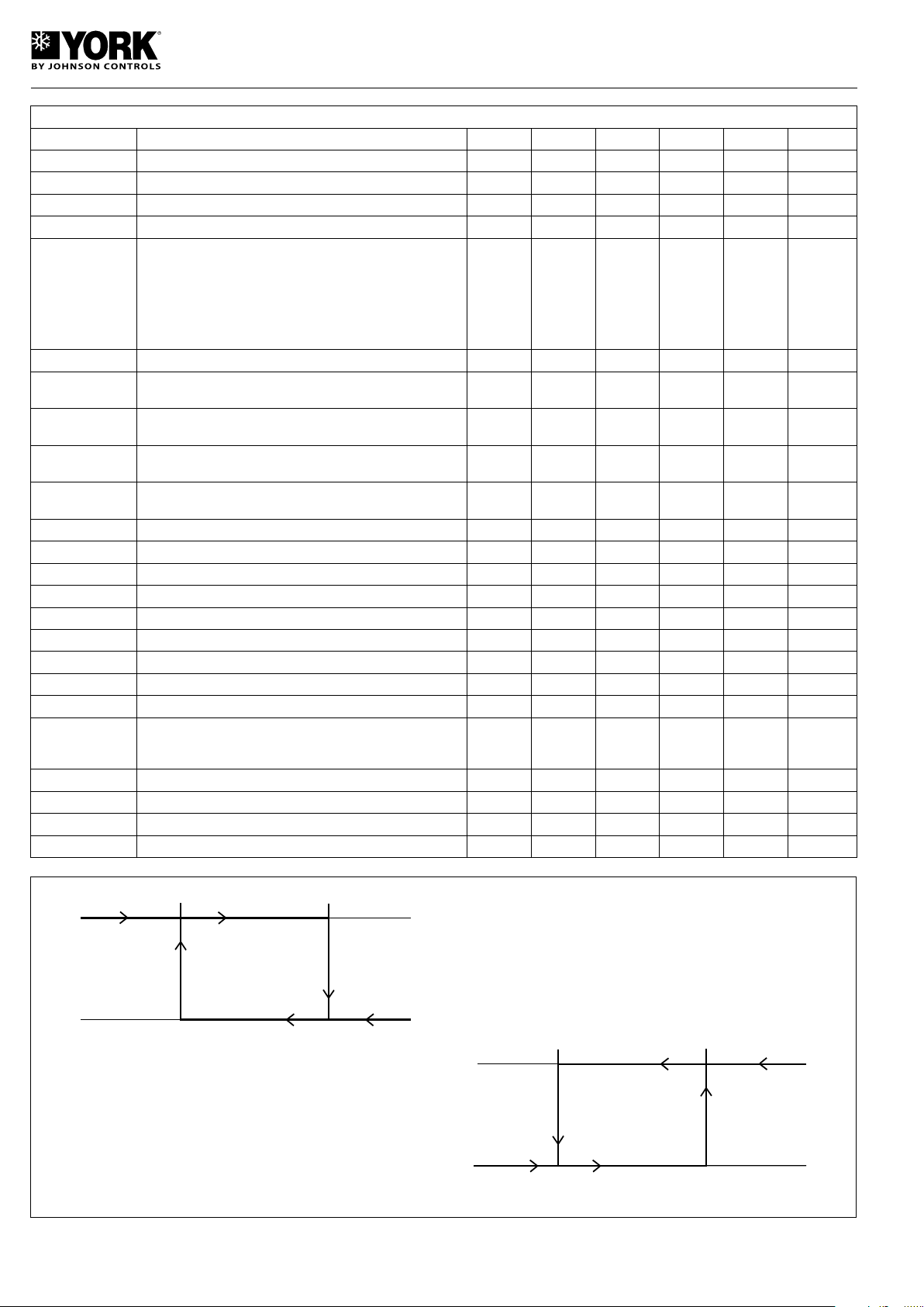
Parameters for regulator configuration
Compressor
HEAT r03 set point Heat r03 set point + differential r04
Compressor
Temp.
Temp.
Temp.
Compressor
COOL r01 set point FRIO r01 set point + differential r02
Compressor
Temp.
Display Description Level VS Unit Max. Min. Value
r01
r02
r03
r04
Cool cycle set point temperature U 41 (R/W) °C r14 r13
Cool set point temperature differential U 42 (R/W) °C 50 0.3
Heat cycle set point temperature U 43 (R/W) °C r16 r15
Heat cycle set point temperature differential U 44 (R/W) °C 50 0.3
12
1
40
2
Type of adjustment
0= Proportional. Intake temperature.
1= Proportional + neutral zone. Intake temp.
r06
2= Proportional. Output temperature.
F 79 (R/W) 4 0
0
3= Proportional + neutral zone. Output temp.
4= By time + dead zone. Output temperature (chillers
only).
r07
r08
r09
r10
r11
r12
r13
r14
r15
r16
r17
r18
r19
r20
Neutral zone differential F 45 (R/W) °C 50 0
(If r06=4 only) Maximum activation time.
Output temperature.
(If r06=4 only) Minimum activation time.
Output temperature.
(If r06=4 only) Maximum deactivation time.
Output temperature.
(If r06=4 only) Maximum deactivation time.
Output temperature.
F 80 (R/W) sec. 999 r09
F 81 (R/W) sec. 999 c04
F 82 (R/W) sec. 999 r11
F 83 (R/W) sec. 999 c05
(If r06=4 only) Compressor deactivation differential. F 46 (R/W) °C 50 0
Cool cycle minimum set point temperature. U 47 (R/W) °C r14 -40
Cool cycle maximum set point temperature. U 48 (R/W) °C 80 r13
Heat cycle minimum set point temperature. U 49 (R/W) °C r16 -40
Heat cycle maximum set point temperature. U 50 (R/W) °C 80 r15
Summer compensation constant U 51 (R/W) - +5 -5
Maximum distance set point U 52 (R/W) °K 20 0.3
Summer compensation start-up temperature U 53 (R/W) °C 176 -40
Winter compensation start-up temperature U 54 (R/W) °C 176 -40
1
120
100
120
100
1
6
20
25
45
-0.4
3.2
32
5
Suppression of buffer tank. 0= No suppression. 1= Sup-
r27
pression in cool cycle. 2= Suppression in heat cycle. 3=
F 88 (R/W) 3 0
3
Permanent suppression.
r28
r29
r30
r31
Minimum time for determining low charge F 89 (R/W) sec. 999 0
Low charge differential in cool cycle F 58 (R/W) °C 50 0.3
Low charge differential in heat cycle F 58 (R/W) °C 50 0.3
Winter compensation constant U 60(R/W) - +5 -5
210
3
4
-0.4
50
Page 51
Table of alarms
Display Alarm type Reset
A1
AHt
ALt
d1-2
dF1-2
E1
E2
E3
E4
ELS
EHS
EPr
EPb
ESP
EL
FL
Hc
HP
Ht
L
LP
Antifreeze alarm Manual
High temp. at start-up (if activated. P20=1) Automatic
Low temp. at start-up (if activated. P20=1) Automatic
Defrost in operation Problem in defrost Automatic
Probe B1 Automatic
Probe B2 Automatic
Probe B3 Automatic
Probe B4 Automatic
Low supply voltage Automatic
High supply voltage Automatic
Eprom error. Unit in operation. Automatic
Eprom error. At start-up Automatic
Communication failure with expansion module Automatic
Problem at fan voltage control Automatic
Flow switch / Pump switch Manual
Compressor maintenance alarm Automatic
High pressure / Fan heat switch Manual
High water temperature alarm
Low charge warning
Low pressure Manual
Automatic
Automatic
Reset of alarms
Pressing the UP and DOWN keys for 5 seconds cancels
alarms present in the memory. At the same time, the alarm
message disappears from the display and the alarm relay
is deactivated.
Forced defrost (heat pumps)
Pressing the SEL and UP keys simultaneously for 5 seconds
activates forced defrost of the unit.
Clearing hour counters
While reading compressor or pump (c10 and c15) operating
hours, said counters can be cleared by pressing the UP and
DOWN keys simultaneously.
Pump operation
4 operating modes can be selected in accordance with the
value given to parameter H5. H5=0 (pump disabled), H5=1
(pump permanently on), H5=2 (pump on controlled by the
regulator or in parallel with the compressor), H5=3 (pump
starts and stops at regular intervals, independent of compres-
sor operation) (parameters c17 and c18).
Calibration of probes
If necessary, probes can be calibrated by using parameters /13,
/14, /15, and /16, See Parameters related to probes table.
Remote ON/OFF
A remote ON/OFF intake can be connected between terminals D5 and B of the connecting strip. To activate said intake,
a value of 1 should be given to parameter H07 (H07= 1).
With this intake open the unit is OFF; when closed, the unit
is ON. This function does not disable the ON/OFF function
of the keyboard.
Remote COOL/HEAT
A remote COOL/HEAT intake can be connected between
terminals D2 and B of the connecting strip. To activate said
intake, a value of 1 should be given to parameter H06 (H06=
1). With this intake open the unit is in HEAT; when closed, the
unit is in COOL. This function does not disable the COOL/
HEAT function of the keyboard.
51
Page 52
Temperature/resistance characteristics of the NTC control probes (10 kOhms)
Temperature
(°C)
-50 329.20
-49 310.70
-48 293.30
-47 277.00
-46 261.80
-45 247.50
-44 234.10
-43 221.80
-42 209.80
-41 198.70
-40 188.40
-39 178.30
-38 168.90
-37 160.10
-36 151.80
-35 144.00
-34 136.60
-33 129.70
-32 123.20
-31 117.10
-30 111.30
-29 106.70
-28 100.40
-27 95.47
-26 90.80
-25 86.39
-24 82.22
-23 78.29
-22 74.58
-21 71.07
-20 67.74
-19 64.54
-18 61.62
-17 58.66
Resistance
(kOhms)
Temperature
(°C)
-16 55.95
-15 53.99
-14 50.90
-13 48.66
-12 46.48
-11 44.41
-10 42.45
-9 40.56
-8 38.76
-7 37.05
-6 35.48
-5 33.89
-4 32.43
-3 31.04
-2 29.72
-1 28.47
0 27.28
1 26.13
2 25.03
3 23.09
4 22.09
5 22.05
6 21.15
7 20.20
8 19.48
9 18.70
10 17.98
11 17.24
12 16.55
13 15.90
14 15.28
15 14.68
16 14.12
17 13.57
18 13.08
19 12.58
20 12.09
21 11.83
22 11.20
23 10.78
24 10.38
25 10.00
Resistance
(kOhms)
Temperature
(°C)
26 9.63
27 9.28
28 8.94
29 8.82
30 8.31
31 6.01
32 7.72
33 7.45
34 7.19
35 6.94
36 6.69
37 6.46
38 6.24
39 6.03
40 5.82
41 5.63
42 5.43
43 5.24
44 5.08
45 4.91
46 4.74
47 4.59
48 4.44
49 4.30
50 4.16
51 4.02
52 3.80
53 3.77
54 3.65
55 3.53
56 3.42
57 3.31
58 3.21
59 3.11
60 3.02
61 2.92
62 2.83
63 2.75
64 2.66
65 2.58
66 2.51
67 2.43
Resistance
(kOhms)
Temperature
(°C)
100 0.97
101 0.94
102 0.92
103 0.90
104 0.87
105 0.85
106 0.83
107 0.81
108 0.79
109 0.77
Resistance
(kOhms)
68 2.36
69 2.29
70 2.22
71 2.16
72 2.10
73 2.04
74 1.98
75 1.92
76 1.87
77 1.81
78 1.76
79 1.71
80 1.66
81 1.62
82 1.57
83 1.53
84 1.49
85 1.45
86 1.41
87 1.37
88 1.33
89 1.30
90 1.26
91 1.23
92 1.20
93 1.16
94 1.13
95 1.10
96 1.06
97 1.05
98 1.02
99 0.99
52
Page 53
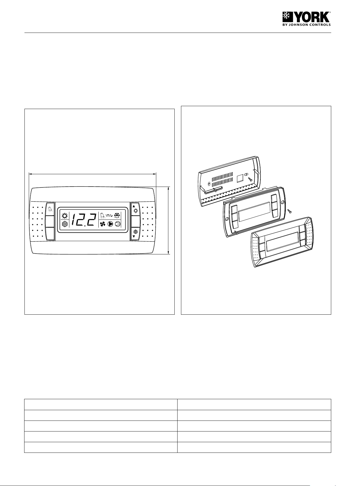
Accessories
156
82
Set
1
2
3
4
Set
Prg
Sel
A
B
Remote terminal
This accessory allows remote control and supervision of the
air conditioning unit (up to 1040 m.). Functions are the same
as the standard control panel keyboard. This remote terminal
is compatible with said keyboard, and the air conditioning unit
can be accessed from both devices. For this application, it
must be connected to the system by means of the RS485
serial line connection accessory.
Wall-mounting
For wall-mounting, the rear support (A) must be fastened to
a standard three-switch modular box.
- Fasten the rear of the casing to the box by means of the
two round head screws.
- Connect the telephone cable.
- Lean the control unit on the rear casing and fasten by
means of the two flat head screws (B).
- Fasten the front panel by applying slight pressure.
Wiring
Connect the RS485 serial device (separate accessory) to the RJ12 power supply outlet (included with the remote terminal)
and to the electric panel keyboard supervising connection, by using shielded cable. Power terminals G-G0 by means of a
transformer and a 250mAT fuse as per the diagram enclosed. Carry out connection between power supply RJ12 and the
remote terminal, using the telephone cable supplied (80 cms.). This cable can be replaced by a longer cable of up to a
maximum of 40 m.
Attention:
- Use safety transformers only (3VA, class 2).
- For safety purposes, a 250mA slow fuse should be inserted in series with the G terminal.
- Do not ground transformer secondary.
Maximum distance to RS485 1 km. (insert a 120-ohm 1/4W resistor in RS485)
Speed 19.200 bauds
Cable characteristics 2 stranded cables with shielding
Cable section AWG22 (0.35 mm²)
Capacity per metre >90pF/m (for example. BELDEN 8761-8762 cable)
53
Page 54
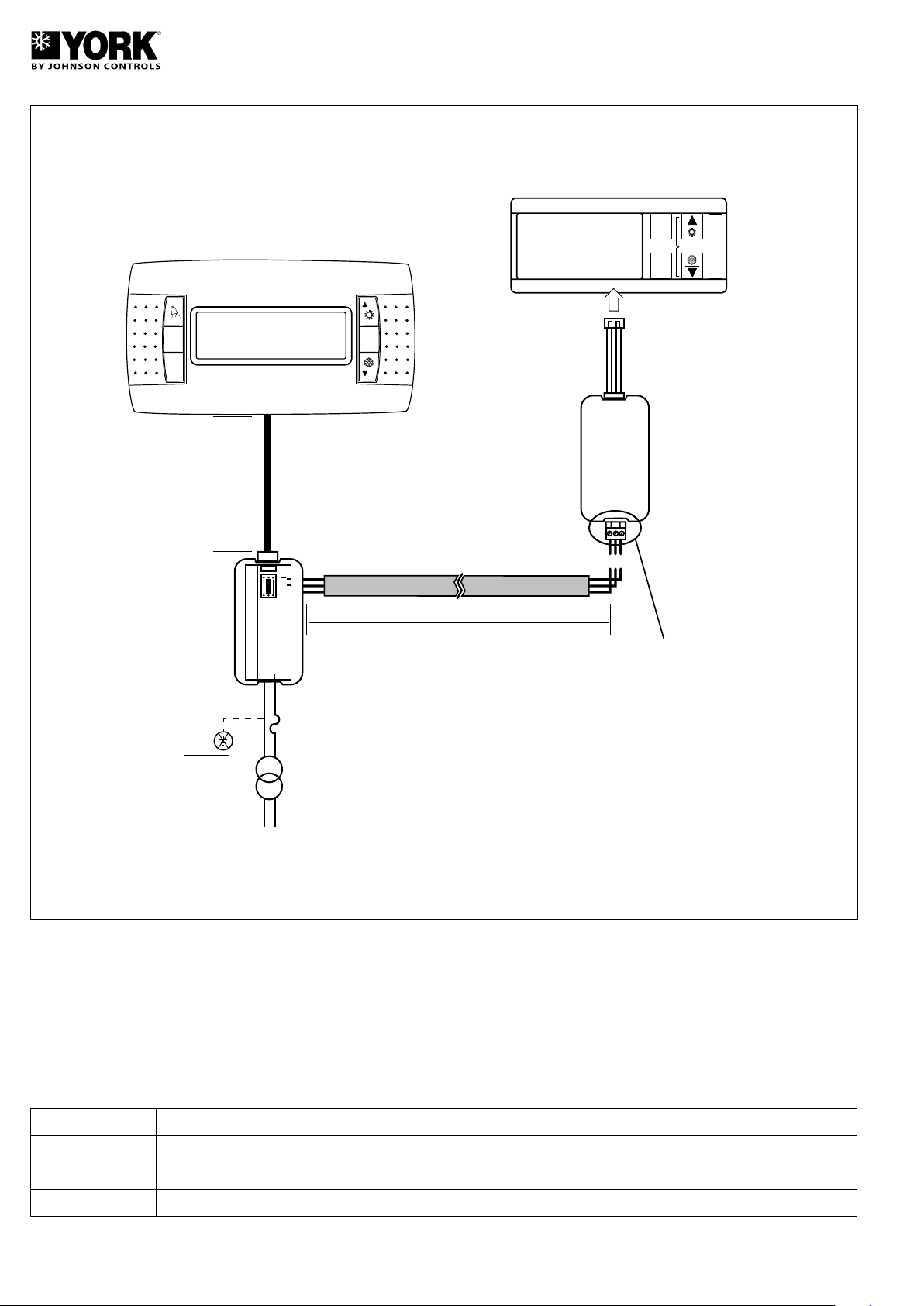
SetSet
Prg
Sel
mute
clear
SEL
PRG
In lenghts of over 200 m. Insert a
120 resistor between
Tx/Rx+ and Tx/Rx-.
Max. L.= 40m
RJ12
Power supply
RJ12 Power supply
GND RS485 24Vac
G
8
N F
3 VA
CLASS 2
Max. L = 1000m
G0 G
SLOW
250 mA
fuse
RS485
TELEPHONE
CABLE
G + -
NO
2 stranded cables with shielding
AWG22 (0.35 mm )
Rx/Tx+. Rx/Tx-. Gnd
2
Installation
No configuration is necessary for the remote terminal to be operative, because the terminal operates whatever the control
serial direction might be (can be selected by means of parameter H10). At start-up, the screen will display the control version. After 4 seconds, all symbols will be displayed. Should the connection to the RS485 not be correct, or the control unit
is set to OFF, the message offline is displayed.
Info mode
Pressing the up, down and sel keys simultaneously for over 6 seconds, four lines are displayed with information on the
system and communications.
Line 1 Terminal version
Line 2 Control unit version
Line 3 Control supervision direction
Line 4 Error percentage between the terminal and the control unit
54
Page 55
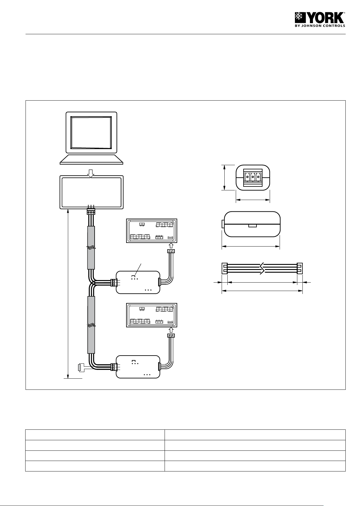
Connecting serial line RS485
31
RS485 SERIAL LINE
CONNECTION
55 75
85
31
24
1/4w
1000 m
PC485KIT00
120 �
GND
T+
T-
1
N
Posistion of
internal jumper
GND
T+
T-
GNDT+T-
GATEWAY
PC
This accessory allows connecting the air conditioning unit to a serial line RS485 supervision network. It must also be used
to install the remote terminal accessory.
Mounting
Connect the accessory to the four-pole socket base at the lower right angle of the module with display and keyboard. Use
the 4-cable connector supplied. Connect to the supervising system as indicated in the drawing below.
The series should be terminated by connecting a 120-ohm 1/4W resistor between terminals TxRx+ and TtxRx-.
Attention:
- Secure the device inside the electric panel so as to avoid accidental disconnection.
- Interconnect after having turned power supply off first.
- Keep the serial connection cables away from the power supply cables.
Maximum distance supervision 1000 m. (insert a 120-ohm 1/4W resistor in the last RS485 connection)
Speed 19.200 bauds
Cable characteristics 2 stranded cables with shielding
Cable section AWG22 (0.35 mm2)
55
Page 56
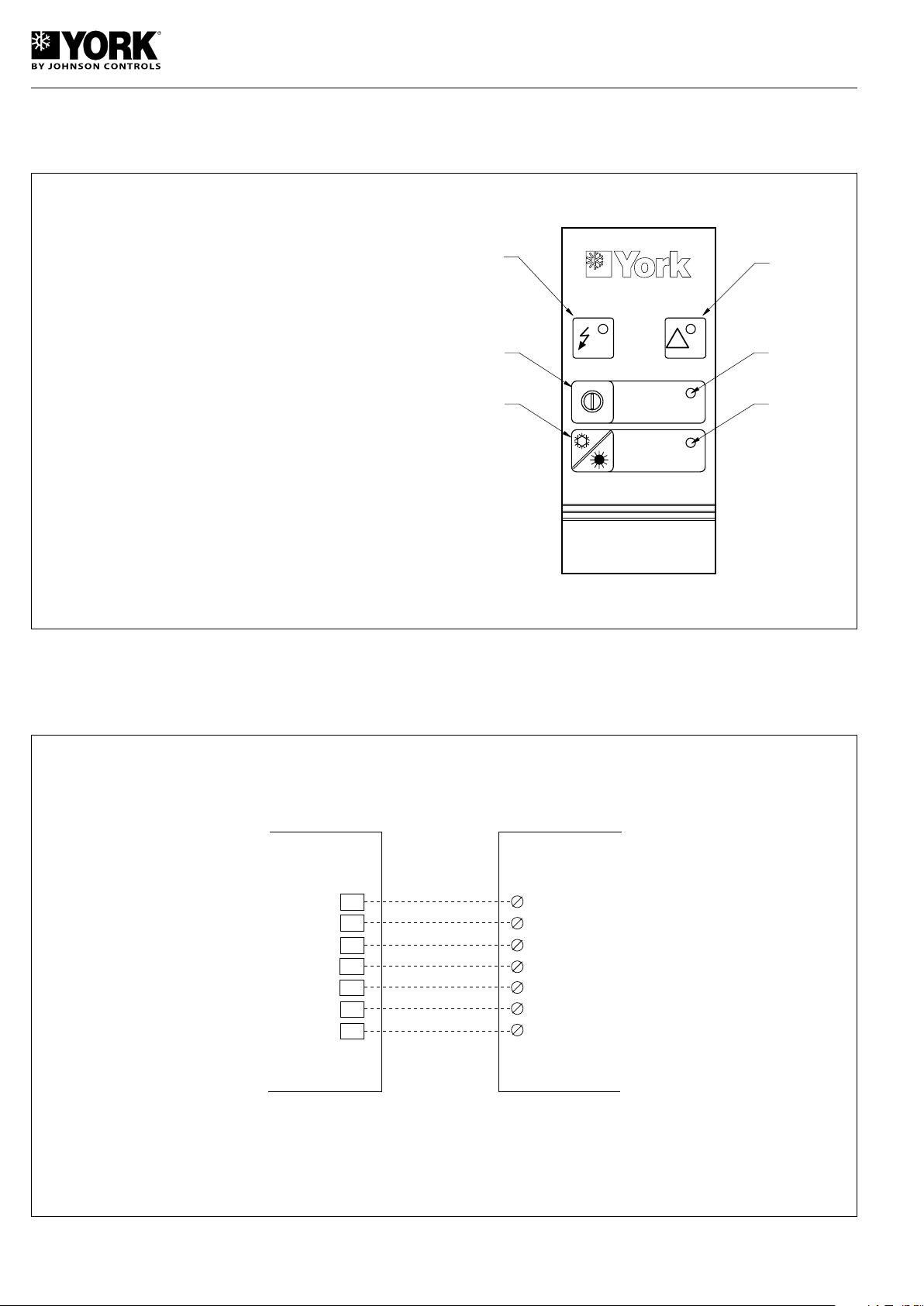
Remote control unit
!
1
2
4
6
3
5
REMOTE CONTROL
24 Vac
REMOTE CONTROL
CONTROL PANEL
1
2
3
4
5
6
7
Alarm
ON/OFF
COOL/HEAT (1)
COMMON
(1) On heat pump units only
F1
D5
N5
C5
G0
D2
GND
Wall-mounted, with keys for COOL/HEAT and ON/OFF functions. Includes voltage, alarm and COOL/HEAT LEDs. Prior to
installation, value 1 must be given to parameters H06 and H07.
1- Voltage LED
2- Alarm LED
3- ON/OFF selection button
4- Unit ON LED
5- COOL/HEAT selection button
6- LED on in heat function/
LED off in cool function.
- The remote control unit can be located at a maximum distance of 50 m.
- Minimum cable section should be 0.35 mm
2
.
- Avoid passing control cables near power supply cables.
Connection to control panel
56
Page 57
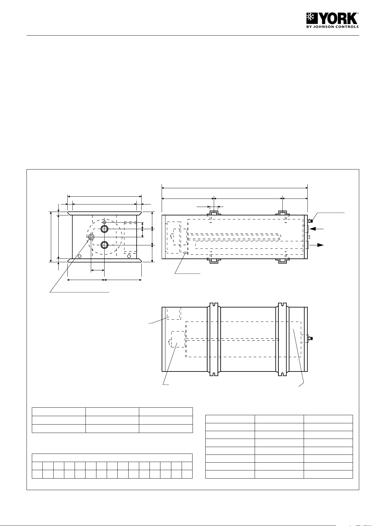
Buffer Tank YLCA/YLHA PLUS 5, 7, 9, 12 and 15
A
B 430 151
50
DRAIN
WATER
INTAKE 1"F
WATER
OUTLET 1"F
WATER RECHARGE 3/8" F
AIR PURGER
460
404 28
309
269 20
4350
130 10574
85
230 230
20
28
CONNECTION BOX
HEATER
BUFFER TANK
For installations with small water volumes in wich it is necessary to increase thermal inertia.
The installation of this unit achieves greater pressure in the
water temperature of the installation and lowers the on/off
cycles of the compressor.
Casing
Made up of screwed-on detachable panels that give access to the internal components. These panels are made of
aluminium steel, painted electrostatic with epoxy-polyester
powdered paint with a thickness of 60 microns to insure efficient protection of the entire surface.
Tank
Made of steel sheeting and galvanized by immersion. It is
coated with 10 mm, thick closed cell reticulated expanded
polyethylene and an a coat of embossed aluminium. There
is an air bleeder at the top and two connections for draining
and charging the circuit in the middle and bottom. This tank
allows a maximum pressure of 6 bar.
Location
It can be installed horizontally or vertically, away from the
cooling unit.
It can be located directly on the floor, both indoors as well
as outdoors.
Backup heater (YLHA PLUS)
Tanks with a backup heater are available. See the variant
chart. These tanks can be controlled by the main regulator
of the heat pump it self.
These kits have an electric connecting box inside.
Note: This accessory includes a flexible 1.050 mm,
flexible hose, two 1” MALE/FEMALE connections, two
Curalite flat gaskets and 1 m, of isolation shielding
for the house.
Pressure drop of the 20 and 30 (kPa) buffer tanks
(Including interconnecting flexible hose)
1000 1250 1500 1750 2000 2250 2500 2750 3000 3250 3500 3750 4000 4250 4500
0 0.5 1.2 2.2 3.4 4.8 6.1 7.6 9 10.8 12.8 14.9 17.1 19.3 21.6
Buffer tank A B
20 litres 907 326
30 litres 1007 426
Flow (l/h)
Variants
Units Buffer tank Heater
5, 7, 9
9, 12, 15
5, 7
5, 7
7, 9
9, 12
12, 15
20 litres -
30 litres -
20 litres 2 kW/230M
20 litres 3 kW/230M
20 litres 3 kW/400T
30 litres 4.5 kW/400T
30 litres 6 kW/400T
57
Page 58
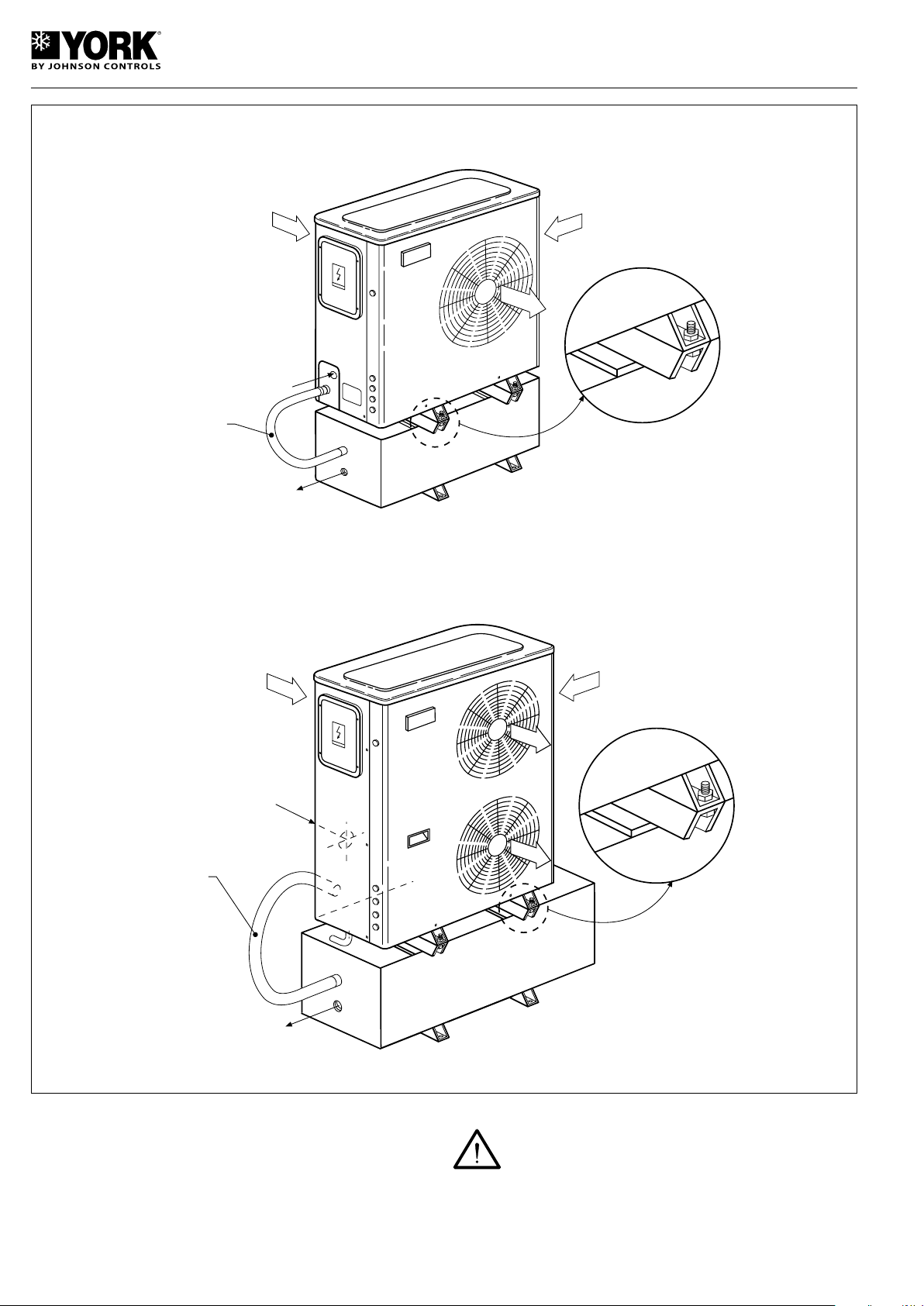
Mounting on 5, 7 and 9 units
DETAIL "A"
WATER
INTAKE
FLEXIBLE
HOSE
WATER
DISCHARGE
WATER
INTAKE
FLEXIBLE
HOSE
WATER
DISCHARGE
DETAIL "A"
Mounting on 12 and 15 units
1. Fasten the buffer tank to the unit (Detail A) by means of
the screws supplied with the accessory.
2. Hydraulically interconnect the buffer tank to the unit by
means of the flexible hose, the two other hoses and the
two Curalite gaskets supplied with the accessory. Cover
the hose with isolation.
58
Attention:
Before starting the system, purge the air from the
tank and the hydraulic circuit.
If an electric heater is installed, do not power the unit
until the circuit if full of water.
The heater includes a manual restart thermostat set to 95° C.
Page 59
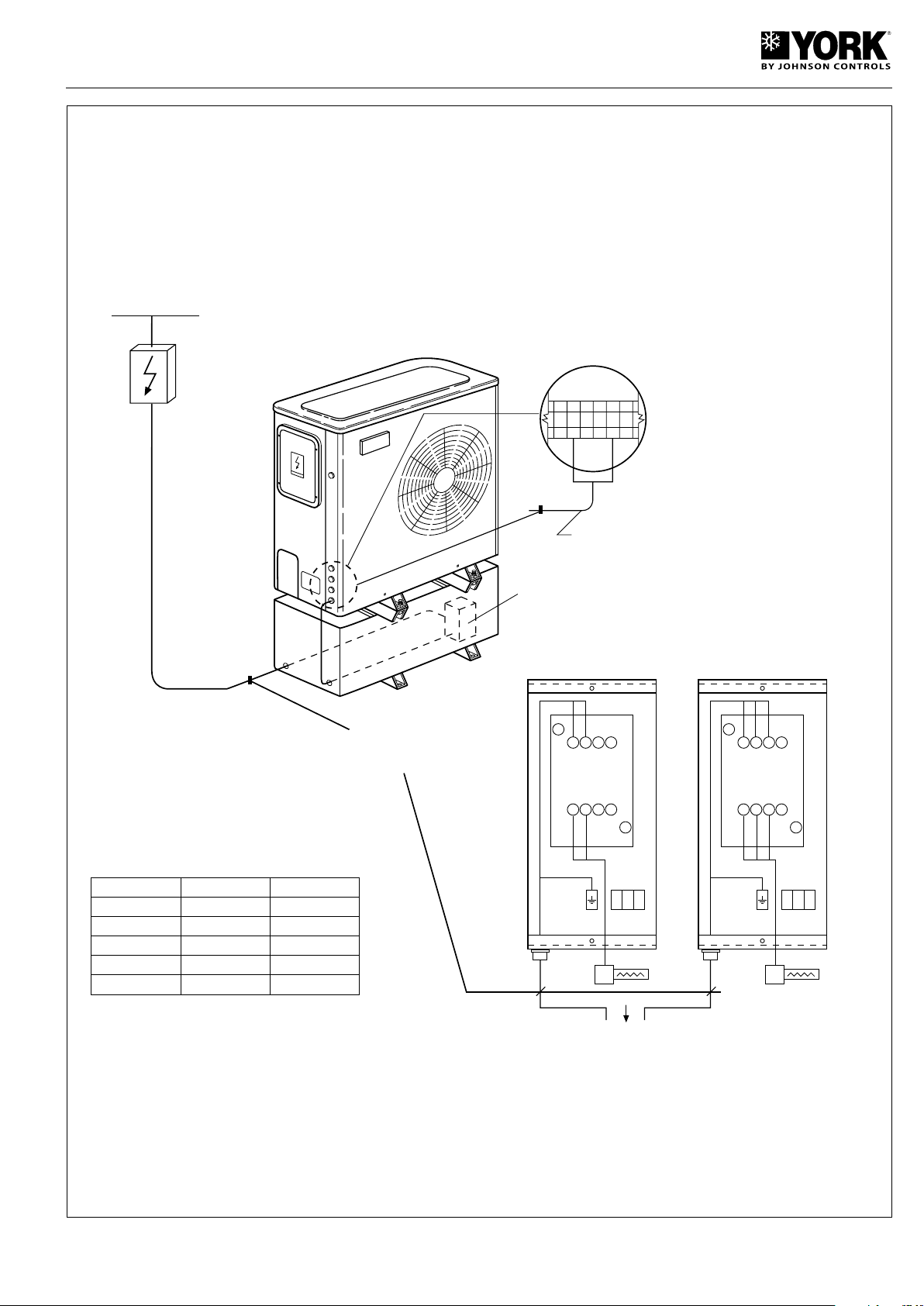
MAGNETOTHERMAL
HEATER PROTECTION (Q1)
POWER SUPPLY
CONNECTING BOX
HEATER POWER SUPPLY
CABLE (NOT INCLUDED
WITH THE ACCESSORY)
1 2 3 N1 N2 N3
HEATER CONNECTING CABLE TO CONTROL
PANEL (INCLUDED WITH THE ACCESSORY)
WIRING OF THE HEATER
(See wiring diagram of the unit)
1133 5
2144 6
A1
A2
(K2)
K 2
N2
HEATER
(AH)
MAGNETOTHERMAL
HEATER PROTECTION (Q1)
230M
400T
CONNECTING BOX
HEATER
CONTACT
1133 5
2144 6
A1
A2
(K2)
K 2
N2
HEATER
(AH)
HEATER
CONTACT
HEATER CABLE mm2 Cu Q1 (A)
2 kW/230M 2.5 15
3 kW/230M 2.5 15
3 kW/400T 1.5 6
4.5 kW/400T 1.5 8
6 kW/400T 2.5 15
59
Page 60
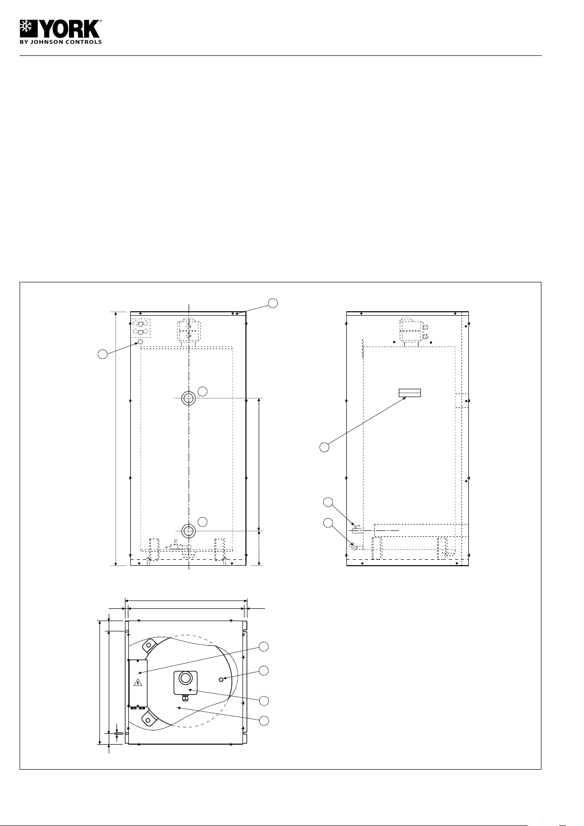
160
577
1120
10
5
6
11
8
9
1
2
3
4
8.5
532
515
8.5
47450
543
46
9
7
115 Litre Buffer Tank for YLCA/YLHA PLUS 20
and 27
Adequate for installations with low water volume and need
to have increased thermal inertia.
This application achieves improved water temperature in
the installation and decreases the on and off cycles of the
compressor.
Casing
Made up of screwed-on detachable panels that give access to the internal components. These panels are made of
aluminium-coated steel sheeting with a 60 micron coating
of epoxy-polyester powdered paint, that assures efficient
protection of the entire surface.
Tank
Made of steel sheeting and galvanized by immersion. It is
General dimensions mm.
coated with 10 mm, thick, closed cell, reticulated and expanded polyethylene, and a coat of embossed aluminium. At
the top it has an automatic bleeder, and two manual valves at
the bottom for draining and recharging the circuit. This tank
allows a maximum pressure of 6 bar.
Location
It should always be installed in vertical position. It can be
placed directly on the floor, both indoors as well as outdoors.
Backup heater (YLHA PLUS)
There are tanks available with a 10.5 kW (400.3.50) backup
heater that can be controlled by the main regulator of the
heat pump itself.
These kits have an internal electrical connections box.
1. 115 litre buffer tank.
2. 10.5 kW backup heater - 400.3.50 (optional).
3. Automatic bleeder.
4. Electrical connections box (in units with heater only).
5. Water intake 1 ¼” GF.
6. Water discharge 1 ¼” GF.
7. Manual recharge valve 3/8” GF.
8. Manual drain valve.
9. Transportation handle.
10. Drilled holes for cables (3 x 22 mm, dia.).
11. Access cover.
60
Page 61
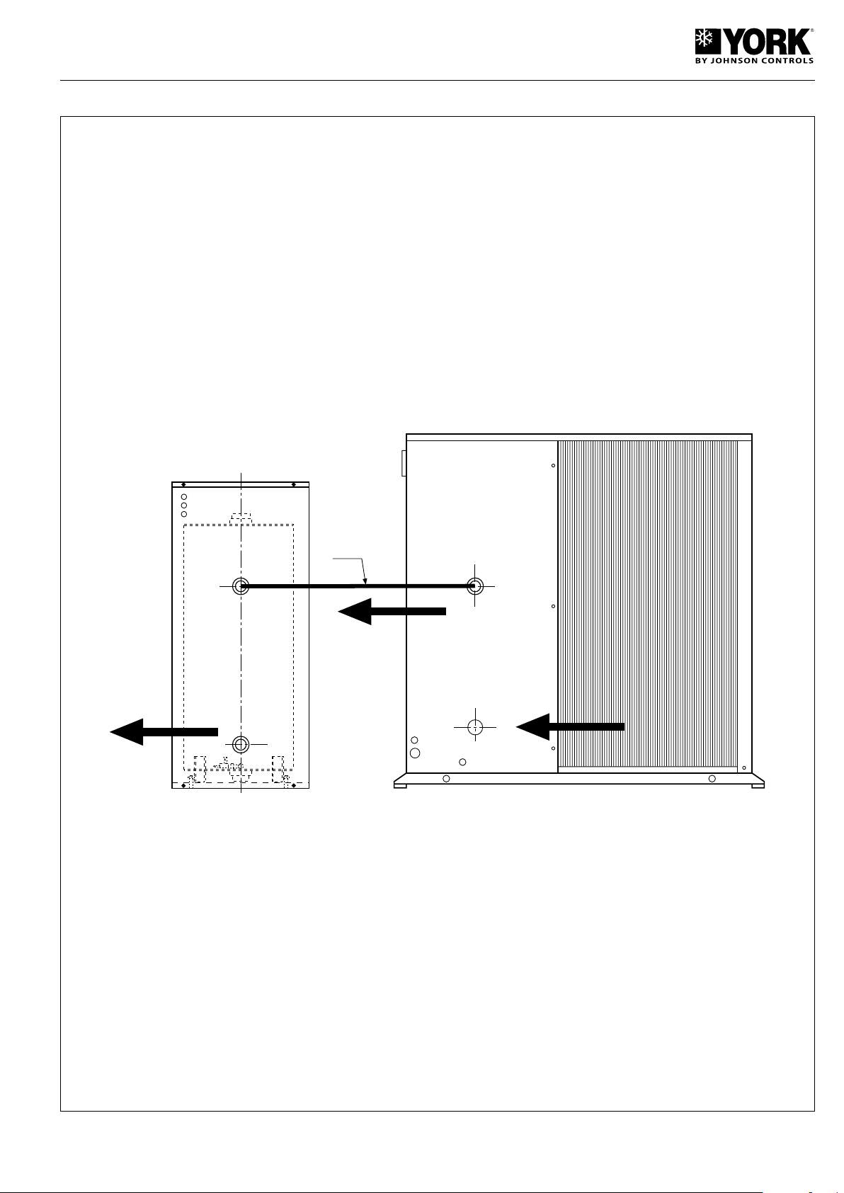
N1
N3
N2
Hydraulic connections
YLCA/YLHA PLUS 20 and 27
N1. Interconnecting tubing (must be insulated to avoid condensation)
N2. Water outlet.
N3. Water intake.
61
Page 62
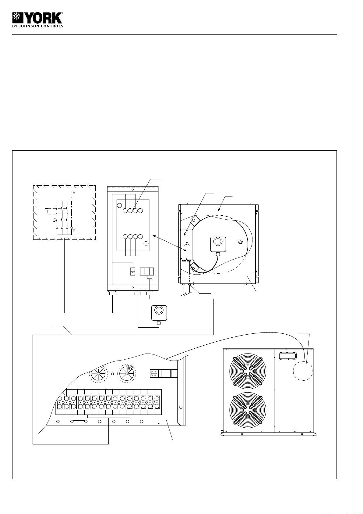
1133
5
2
14
4
6
A1
A2
(K2)
K 2
N2
EBBT
AH
AH
N6
N2
N1
10.5 kW
BT
1
1
1
4 5
6 N
1N2N3
N4
N5
C5
3
2
2
2
4 5
6 N
1N2N3
N4
N5
C5
3
2
2
2
X2
EBHP
N4
L1
L1
L2
Q1
400V
.
3 ~.50Hz.
L3
L2
L3
20A
N3
N5
Wiring of the heater
- Prior to installation, power off the YLHA PLUS units.
- Do not power on again until installation is finished and with
the tank full of water.
AH - 10.5 Kw backup heater (400.3.50).
BT - Buffer tank.
EBBT - Buffer tank connections box.
EBHP - YLHA PLUS connections box.
K2 - Heater contactor.
Q1 - Thermomagnetic protector of the heater.
Wiring of the heater
Installation
N1 - Remove the top cover of the tank.
N2 - Remove the cover of the connections box.
N3 - Remove the cover of the YLHA PLUS control box.
N4 - Connect terminals 2 and N2 of the tank connections
box to the corresponding terminals in the YLHA PLUS
electrical connections box.
N5 - Connect terminals 1, 3 and 5 of contactor K2 and
ground of the tank electric box to the power supply.
For this purpose, use 2.5 mm² Cu cable and a thermomagnetic 20 amp switch.
N6 - Pass the cables through the tank the corresponding
drilled holes.
62
Page 63
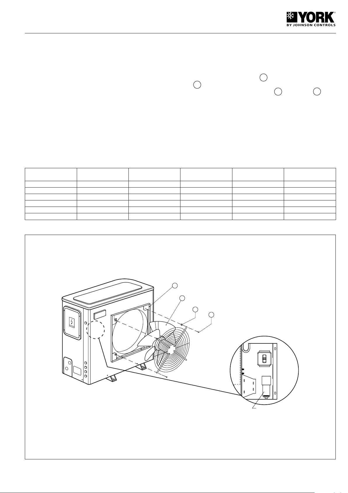
High pressure fan YLCA/YLHA PLUS 5-27
1
2
4
3
C2
LOCATION OF
CONDENSER
Units 5, 7 and 9
This accessory includes:
- 1 fan.
- 1 connecting nozzle for fitting on the front panel.
- 1 condenser for fitting on the control box.
- 1 4A magneto thermal switch.
their connecting points on the control box.
2. Replace the standard fan condenser with the condenser
supplied with the accessory.
3. Remove the standard fan from its housing. Save the
screws and rubber supports.
4. Fit the high pressure fan 1 , inserting the duct nozzle
2 between the supporting panel and the fan grid. Replace the same rubber supports 4 and screws 3 . See
Units 12, 15, 20 and 27
This accessory includes:
- 2 fans.
- 2 connecting nozzles for fitting on the front panel.
- 2 condensers for fitting on the control box.
- 1 6A magneto thermal switch.
enclosed diagram.
5. Connect the high pressure fan electric cables to the same
points where the standard fan was connected.
6. Substitute magneto thermal switch Q3.
7. Check operation and correct centring of the turbine, if
necessary.
Installation
1. Disconnect the electric cables of the standard fan from
Characteristics of the high pressure fans
Units
5 60 1 390 78 502 x 502 1
7 and 9 45 1 390 78 502 x 502 1
12 and 15 45 1 390 81 502 x 1 104 2
20 45 1 390 81 502 x 1 104 2
27 40 870 79 610 x 1 215 2
40 130 1 370 84 2 x Diam. 600 2
AVAILABLE PRESSU-
RE (Pa)
RPM Lw (Db) MAX. SPEED
DUCT DIMENSIONS
(mm)
FAN QUANTITIES
Installation details
Units 5, 7 and 9
63
Page 64
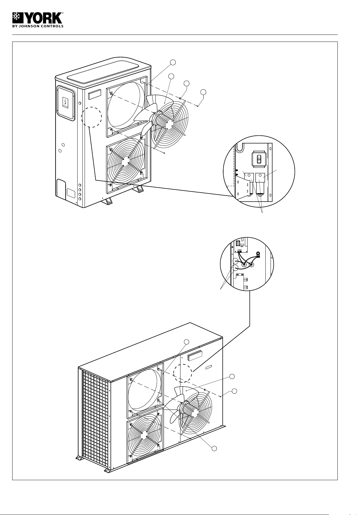
Units 12 and 15
2
1
4
3
C2
LOCATION OF
CONDENSER
C3
LOCATION OF
CONDENSER
2
3
1
4
C2
C3
Units 20 and 27
64
Page 65
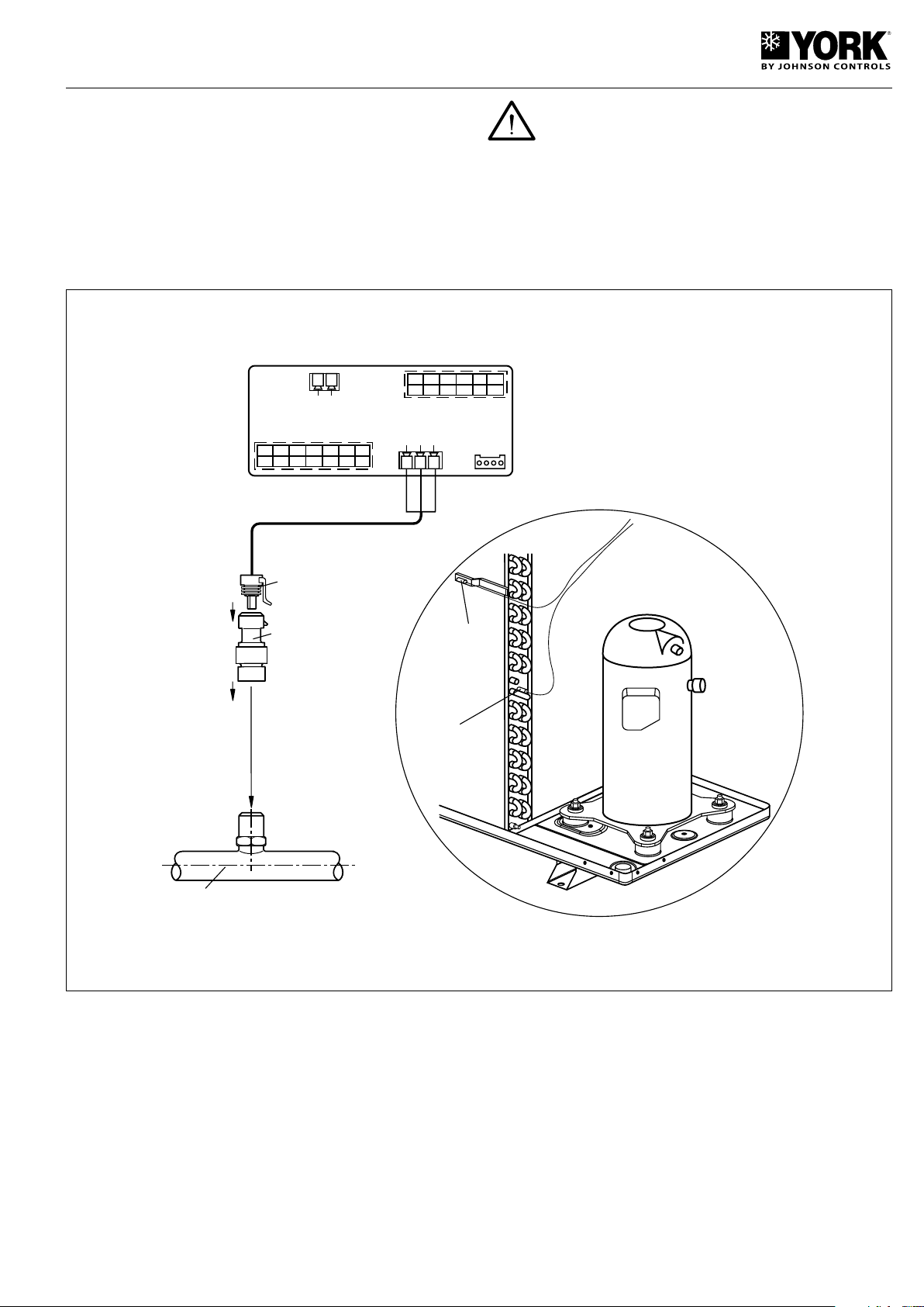
Low ambient temperature kit (ratiometric pres-
POSITION DETAIL PROBE
B3 and B4
PROBE B4
PROBE B3
RATIOMETRIC
TRANSDUCER
PACKARD
CONNECTORS
LIQUID LINE (YLCA)
TERMINAL
Green
White
Black
GND B4 V+
GOGB1
GNDB2GNDB3Y
ID5
GND
ID3
ID4
ID1
ID2
No1
No2
C
½
No3 No4
C¾C5
No5
C
½
C
¾
x
x
sure transducer) YLCA 5-15
To adjust condensing pressure at low ambient temperatures
(down to -18° C).
The kit is comprised of:
1 ratiometric pressure transducer.
1 Packard connector.
1 three-way connector.
Attention: Install the kit with power supply to the
unit turned off.
Mounting pressure transducer on the cooling circuit
Screw the ratiometric transducer on to the free Schrader valve
located on the liquid line (YLCA). Check for leaks.
Mounting the Packard connector
Connect the three Packard connector cables to the three-way
connector and at the regulator module as indicated below.
Eliminate probe B3
Disconnect and remote probe B3 from the connecting strip
located on the coil (condensation/evaporation control).
Replace outdoor probe B4
Disconnect outdoor probe B4 from the rear of the control
module and reconnect it to the terminals that were occupied by probe B3 (GND-B3). With this change, this probe
becomes B3.
Connection of the pressure transducer
Connect the pressure transducer to the three-way connector
that was occupied by B4, which is located at the rear of the
controller. Now this transducer becomes probe B4.
Modifying parameters
- Power the system.
- Select standby on the regulator.
- Enter the parameter programming system by means of the
password.
- Modify and check the following parameters in accordance
with the values indicated: /03= 2; /04= 3; F05= 22.2; F06=
3.7; F07= 6.5; P18= 41.
Start the unit and check operation.
65
Page 66
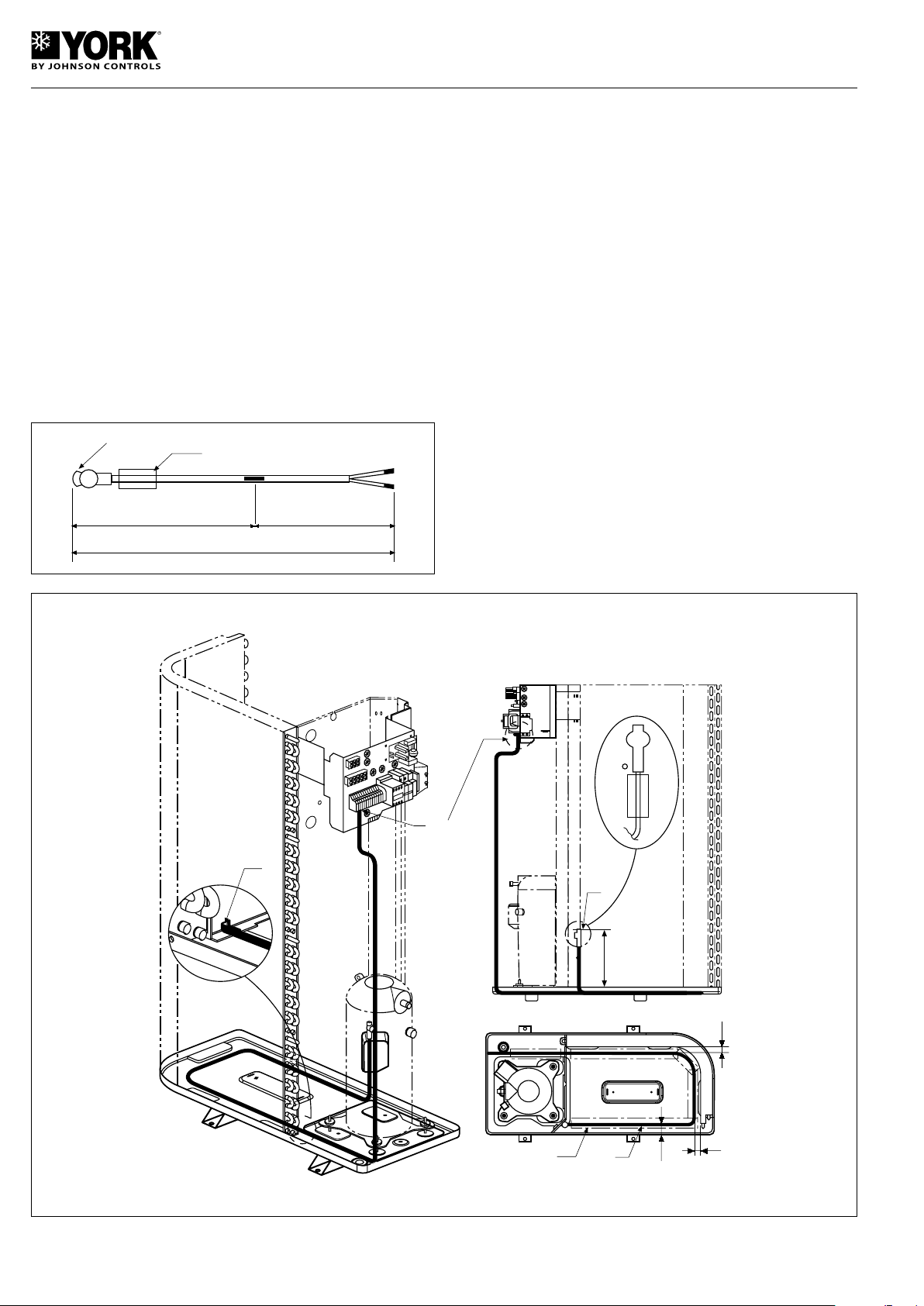
Tray heater YLHA PLUS 5-15
ACTIVE HEATER
COLD LIMIT
2000 1000
3000
THERMOSTAT
SELF-ADHESIVE
ALUMINIUM TAPE
250
30
30
40
N3
N5
N4
N6
N2
This flexible cable heater can be used in cold climates to
avoid the forming of ice and the subsequent obstruction at
the tray drain of the heat pumps.
This accessory includes:
1 Flexible cable heater with a thermostat.
2 m, of 50 mm, self-adhesive aluminium tape.
Heater characteristics
Current: 230.1.50
Power: 80 W
Total length: 3 000 mm
Active heater length: 2 000 mm (contact with the coil)
Cold limit: 1 000 mm (open-air cable and connecting strip
connection)
Heater activation temperature: Indoor ambient 4° C.
Installation
N1- With the power supply turned off. remove the front panel
and the compressor chamber corner piece.
N2 - Fasten the end with the thermostat to the separating
panel of the fan chamber, at the indicated level. Use the
3.5 mm dia.
To fasten said end, us the section of self-ashesive alu-
minium tape installed.
N3- Locate the cable heater over the tray, at the indicated
elevation.
N4 - Pass the cable heater to the compressor chamber
through the rectangular hole at the base of the separating panel. Make sure the cable heater reaches the tray
drain.
N5 - Fasten the cable heater to the tray with the self-adhesive
aluminium tape supplied. Avoid covering the tray drain.
N6 - Connect the two terminal cables of the heater to termi-
nals L1 and N (230.1.50) of the connecting strip.
66
Page 67
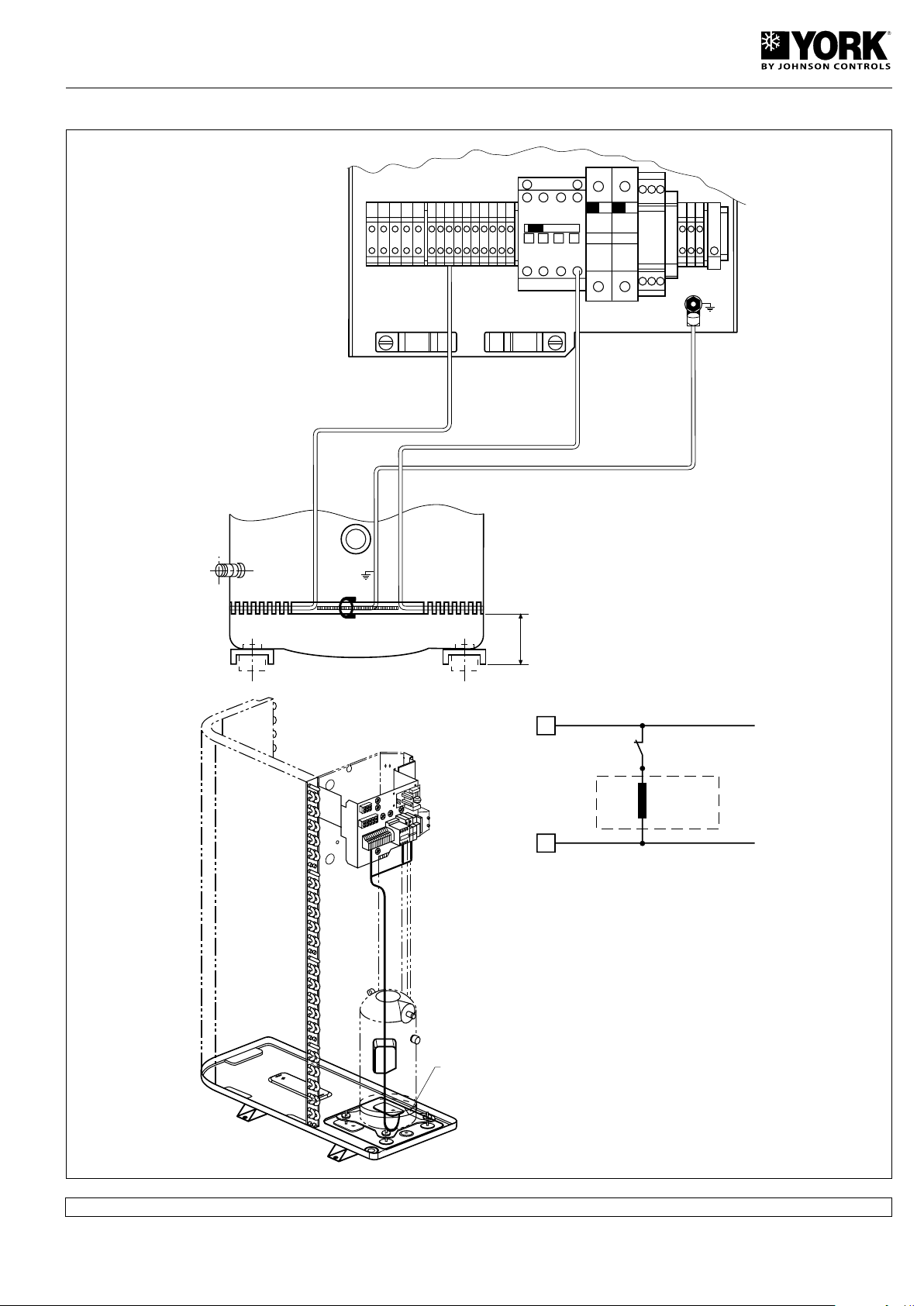
Compressor heater YLHA PLUS 5 - 15
22
K1
2
40
220/240-1-50 (70 W)
CH
1
2
22
21
K1
CH
220/240-1-50
70W
CH
240-1-50
70W
- LENGTHEN THE HEATER CABLES. IF
NECESSARY
CH - COMPRESSOR HEATER
K1 - COMPRESSOR CONTACTOR
Assembly
All data and measurements are subject to change without prior notice.
67
Page 68

www.johnsoncontrols.com
 Loading...