

Page 1

York Commercial Comfort System
System Manager/Zone Coordinator
User’s Manual
YK-SMU2x0-0, YK-ZCU2x0-0, YK-ZCU4x0-0
YCCS System Manager / Zone Coordinator
Page 2

428516-YUM-B-0908
System Manager/Zone Coordinator
User’s Manual
YK-SMU2x0-0, YK-ZCU2x0-0, YK-ZCU4x0-0
TABLE OF CONTENTS
Document Introduction . . . . . . . . . . . . . . . . . . . . . . . . . . . . . . . . . . . . . . . . . . . . . . . . . 6
Related Documentation. . . . . . . . . . . . . . . . . . . . . . . . . . . . . . . . . . . . . . . . . . . . . . . . . 6
System Manager/Zone Coordinator on the Network . . . . . . . . . . . . . . . . . . . . . . . . . 7
System Configuration . . . . . . . . . . . . . . . . . . . . . . . . . . . . . . . . . . . . . . . . . . . . . . . . . . 8
User Interface Overview . . . . . . . . . . . . . . . . . . . . . . . . . . . . . . . . . . . . . . . . . . . . . . . . 8
System Startup. . . . . . . . . . . . . . . . . . . . . . . . . . . . . . . . . . . . . . . . . . . . . . . . . . . . . . . . . . . 8
System Manager/Coordinator Menu Structure . . . . . . . . . . . . . . . . . . . . . . . . . . . . . . . . . 9
Screen Layout . . . . . . . . . . . . . . . . . . . . . . . . . . . . . . . . . . . . . . . . . . . . . . . . . . . . . . . . . . 10
Main Selection Bar. . . . . . . . . . . . . . . . . . . . . . . . . . . . . . . . . . . . . . . . . . . . . . . . . . . . . . . . 10
Title Area . . . . . . . . . . . . . . . . . . . . . . . . . . . . . . . . . . . . . . . . . . . . . . . . . . . . . . . . . . . . . . . 11
Main Display Area . . . . . . . . . . . . . . . . . . . . . . . . . . . . . . . . . . . . . . . . . . . . . . . . . . . . . . . . 11
Help Text/Paging Information Area . . . . . . . . . . . . . . . . . . . . . . . . . . . . . . . . . . . . . . . . . . . 11
Navigation Area . . . . . . . . . . . . . . . . . . . . . . . . . . . . . . . . . . . . . . . . . . . . . . . . . . . . . . . . . . 11
Enter Password Screen. . . . . . . . . . . . . . . . . . . . . . . . . . . . . . . . . . . . . . . . . . . . . . . . . . . 12
Default Passwords Provided . . . . . . . . . . . . . . . . . . . . . . . . . . . . . . . . . . . . . . . . . . . . . . . . 13
Home Screens . . . . . . . . . . . . . . . . . . . . . . . . . . . . . . . . . . . . . . . . . . . . . . . . . . . . . . . . . . 13
Display and Navigation Screens . . . . . . . . . . . . . . . . . . . . . . . . . . . . . . . . . . . . . . . . . . . 14
Data Entry Screens . . . . . . . . . . . . . . . . . . . . . . . . . . . . . . . . . . . . . . . . . . . . . . . . . . . . . . 15
Remote User Interface. . . . . . . . . . . . . . . . . . . . . . . . . . . . . . . . . . . . . . . . . . . . . . . . . . . . 16
Alarms and Alarm Priorities . . . . . . . . . . . . . . . . . . . . . . . . . . . . . . . . . . . . . . . . . . . . . . . 17
Types of Alarms. . . . . . . . . . . . . . . . . . . . . . . . . . . . . . . . . . . . . . . . . . . . . . . . . . . . . . . . . . 17
Buffer Limitation. . . . . . . . . . . . . . . . . . . . . . . . . . . . . . . . . . . . . . . . . . . . . . . . . . . . . . . . . . 18
Alarm Detection . . . . . . . . . . . . . . . . . . . . . . . . . . . . . . . . . . . . . . . . . . . . . . . . . . . . . . . . . . 18
Alarm Destinations . . . . . . . . . . . . . . . . . . . . . . . . . . . . . . . . . . . . . . . . . . . . . . . . . . . . . . 18
Pagers . . . . . . . . . . . . . . . . . . . . . . . . . . . . . . . . . . . . . . . . . . . . . . . . . . . . . . . . . . . . . . . . . 18
2
System Manager/Zone Coordinator User’s Manual
Page 3

428516-YUM-B-0908
E-mail Accounts. . . . . . . . . . . . . . . . . . . . . . . . . . . . . . . . . . . . . . . . . . . . . . . . . . . . . . . . . . 18
Text Messages. . . . . . . . . . . . . . . . . . . . . . . . . . . . . . . . . . . . . . . . . . . . . . . . . . . . . . . . . . . 19
Zones, Groups, and Members . . . . . . . . . . . . . . . . . . . . . . . . . . . . . . . . . . . . . . . . . . . . . 19
Event Scheduling. . . . . . . . . . . . . . . . . . . . . . . . . . . . . . . . . . . . . . . . . . . . . . . . . . . . . . . . 19
Temporary Occupancy Override . . . . . . . . . . . . . . . . . . . . . . . . . . . . . . . . . . . . . . . . . . . . . 19
All Schedules - Temporary Occupancy . . . . . . . . . . . . . . . . . . . . . . . . . . . . . . . . . . . . . . . . 20
Exception Schedules . . . . . . . . . . . . . . . . . . . . . . . . . . . . . . . . . . . . . . . . . . . . . . . . . . . . . . 20
Global and Instant Shutdown . . . . . . . . . . . . . . . . . . . . . . . . . . . . . . . . . . . . . . . . . . . . . . 20
Trend Data Collection . . . . . . . . . . . . . . . . . . . . . . . . . . . . . . . . . . . . . . . . . . . . . . . . . . . . 20
Display Units . . . . . . . . . . . . . . . . . . . . . . . . . . . . . . . . . . . . . . . . . . . . . . . . . . . . . . . . . . . 21
Maintenance Procedures . . . . . . . . . . . . . . . . . . . . . . . . . . . . . . . . . . . . . . . . . . . . . . . . . 22
Detailed Procedures . . . . . . . . . . . . . . . . . . . . . . . . . . . . . . . . . . . . . . . . . . . . . . . . . . 23
Basic Procedures. . . . . . . . . . . . . . . . . . . . . . . . . . . . . . . . . . . . . . . . . . . . . . . . . . . . . . . . 23
Waking up the Display. . . . . . . . . . . . . . . . . . . . . . . . . . . . . . . . . . . . . . . . . . . . . . . . . . . . . 23
Entering Your Password . . . . . . . . . . . . . . . . . . . . . . . . . . . . . . . . . . . . . . . . . . . . . . . . . . . 23
Logging On the Remote User Interface. . . . . . . . . . . . . . . . . . . . . . . . . . . . . . . . . . . . . . . . 24
Logging Off the Remote User Interface. . . . . . . . . . . . . . . . . . . . . . . . . . . . . . . . . . . . . . . . 24
Setup Procedures . . . . . . . . . . . . . . . . . . . . . . . . . . . . . . . . . . . . . . . . . . . . . . . . . . . . . . . 25
Setting Date and Time Parameters . . . . . . . . . . . . . . . . . . . . . . . . . . . . . . . . . . . . . . . . . . . 26
Changing the Administrator or Operator Password. . . . . . . . . . . . . . . . . . . . . . . . . . . . . . . 27
Enabling (or Disabling) Password Security . . . . . . . . . . . . . . . . . . . . . . . . . . . . . . . . . . . . . 28
Enabling (or Disabling) the Remote User Interface . . . . . . . . . . . . . . . . . . . . . . . . . . . . . . . 29
Setting up a Modem. . . . . . . . . . . . . . . . . . . . . . . . . . . . . . . . . . . . . . . . . . . . . . . . . . . . . . . 30
Specifying Ethernet Settings . . . . . . . . . . . . . . . . . . . . . . . . . . . . . . . . . . . . . . . . . . . . . . . . 31
Selecting Display Units . . . . . . . . . . . . . . . . . . . . . . . . . . . . . . . . . . . . . . . . . . . . . . . . . . . . 33
Calibrating the Display. . . . . . . . . . . . . . . . . . . . . . . . . . . . . . . . . . . . . . . . . . . . . . . . . . . . . 33
Specifying System Manager/Zone Coordinator Name. . . . . . . . . . . . . . . . . . . . . . . . . . . . . 35
Entering Job Name . . . . . . . . . . . . . . . . . . . . . . . . . . . . . . . . . . . . . . . . . . . . . . . . . . . . . . . 36
Scheduling Procedures. . . . . . . . . . . . . . . . . . . . . . . . . . . . . . . . . . . . . . . . . . . . . . . . . . . 37
Adding a Schedule. . . . . . . . . . . . . . . . . . . . . . . . . . . . . . . . . . . . . . . . . . . . . . . . . . . . . . . . 39
System Manager/Zone Coordinator User’s Manual 3
Page 4

428516-YUM-B-0908
Deleting a Schedule. . . . . . . . . . . . . . . . . . . . . . . . . . . . . . . . . . . . . . . . . . . . . . . . . . . . . . . 41
Adding a Member to a Schedule . . . . . . . . . . . . . . . . . . . . . . . . . . . . . . . . . . . . . . . . . . . . . 42
Deleting a Member from a Schedule. . . . . . . . . . . . . . . . . . . . . . . . . . . . . . . . . . . . . . . . . . 43
Adding an Exception Schedule . . . . . . . . . . . . . . . . . . . . . . . . . . . . . . . . . . . . . . . . . . . . . . 44
Setting up Temporary Occupancy Time . . . . . . . . . . . . . . . . . . . . . . . . . . . . . . . . . . . . . . . 45
Beginning Temporary Occupancy of a Schedule. . . . . . . . . . . . . . . . . . . . . . . . . . . . . . . . . 46
Ending Temporary Occupancy of a Schedule . . . . . . . . . . . . . . . . . . . . . . . . . . . . . . . . . . . 47
Beginning or Ending Temporary Occupancy to All Schedules . . . . . . . . . . . . . . . . . . . . . . 47
Alarm Procedures . . . . . . . . . . . . . . . . . . . . . . . . . . . . . . . . . . . . . . . . . . . . . . . . . . . . . . . 48
Configuring Pager as Alarm Destination . . . . . . . . . . . . . . . . . . . . . . . . . . . . . . . . . . . . . . . 49
Configuring E-mail Account as Alarm Destination. . . . . . . . . . . . . . . . . . . . . . . . . . . . . . . . 50
Configuring Text Message as Alarm Destination. . . . . . . . . . . . . . . . . . . . . . . . . . . . . . . . . 51
Setting Alarm Indicators. . . . . . . . . . . . . . . . . . . . . . . . . . . . . . . . . . . . . . . . . . . . . . . . . . . . 53
Viewing an Alarm Summary. . . . . . . . . . . . . . . . . . . . . . . . . . . . . . . . . . . . . . . . . . . . . . . . . 55
Deleting One or All Alarms. . . . . . . . . . . . . . . . . . . . . . . . . . . . . . . . . . . . . . . . . . . . . . . . . . 56
Summary Procedures . . . . . . . . . . . . . . . . . . . . . . . . . . . . . . . . . . . . . . . . . . . . . . . . . . . . 57
Viewing System Summaries . . . . . . . . . . . . . . . . . . . . . . . . . . . . . . . . . . . . . . . . . . . . . . . . 58
Viewing Trend Data . . . . . . . . . . . . . . . . . . . . . . . . . . . . . . . . . . . . . . . . . . . . . . . . . . . . . . . 59
Zone Setup Procedures. . . . . . . . . . . . . . . . . . . . . . . . . . . . . . . . . . . . . . . . . . . . . . . . . . . 60
Setting Up a Changeover Bypass Zone. . . . . . . . . . . . . . . . . . . . . . . . . . . . . . . . . . . . . . . . 61
Setting Up a CV RTU Zone . . . . . . . . . . . . . . . . . . . . . . . . . . . . . . . . . . . . . . . . . . . . . . . . . 62
Setting up a VAV RTU Zone . . . . . . . . . . . . . . . . . . . . . . . . . . . . . . . . . . . . . . . . . . . . . . . . 64
Editing a Zone Name. . . . . . . . . . . . . . . . . . . . . . . . . . . . . . . . . . . . . . . . . . . . . . . . . . . . . . 66
Viewing Zone Status . . . . . . . . . . . . . . . . . . . . . . . . . . . . . . . . . . . . . . . . . . . . . . . . . . . . . . 67
Copying Zone Setup to All Zones . . . . . . . . . . . . . . . . . . . . . . . . . . . . . . . . . . . . . . . . . . . . 68
Requesting Global Shutdown of all Zones in all Systems . . . . . . . . . . . . . . . . . . . . . . . . . . 69
Viewing Device Diagnostics. . . . . . . . . . . . . . . . . . . . . . . . . . . . . . . . . . . . . . . . . . . . . . . . . 70
Zoning System Setup Procedures . . . . . . . . . . . . . . . . . . . . . . . . . . . . . . . . . . . . . . . . . . 71
Setting Up a Zoning System . . . . . . . . . . . . . . . . . . . . . . . . . . . . . . . . . . . . . . . . . . . . . . . . 72
Viewing Zoning System Status . . . . . . . . . . . . . . . . . . . . . . . . . . . . . . . . . . . . . . . . . . . . . . 74
System Manager/Zone Coordinator User’s Manual4
Page 5

428516-YUM-B-0908
Requesting Instant Shutdown of a Zoning System . . . . . . . . . . . . . . . . . . . . . . . . . . . . . . . 75
Balancing a Zoning System. . . . . . . . . . . . . . . . . . . . . . . . . . . . . . . . . . . . . . . . . . . . . . . . . 76
Auxiliary Points Setup Procedures . . . . . . . . . . . . . . . . . . . . . . . . . . . . . . . . . . . . . . . . . 77
Setting up Auxiliary Points. . . . . . . . . . . . . . . . . . . . . . . . . . . . . . . . . . . . . . . . . . . . . . . . . . 78
Editing an IOM Controller Name . . . . . . . . . . . . . . . . . . . . . . . . . . . . . . . . . . . . . . . . . . . . . 80
Viewing Auxiliary Points Status . . . . . . . . . . . . . . . . . . . . . . . . . . . . . . . . . . . . . . . . . . . . . . 81
Viewing IOM Controller Point Trend Data . . . . . . . . . . . . . . . . . . . . . . . . . . . . . . . . . . . . . . 82
Dial-up Communication Procedures . . . . . . . . . . . . . . . . . . . . . . . . . . . . . . . . . . . . . . . . 83
Creating a Dial-up Connection. . . . . . . . . . . . . . . . . . . . . . . . . . . . . . . . . . . . . . . . . . . . . . . 83
Dialing up a System Manager or Coordinator . . . . . . . . . . . . . . . . . . . . . . . . . . . . . . . . . . . 89
Maintenance Procedures . . . . . . . . . . . . . . . . . . . . . . . . . . . . . . . . . . . . . . . . . . . . . . . . . 90
Backing up Current Configuration . . . . . . . . . . . . . . . . . . . . . . . . . . . . . . . . . . . . . . . . . . . . 91
Restoring Configuration Information . . . . . . . . . . . . . . . . . . . . . . . . . . . . . . . . . . . . . . . . . . 92
Restoring Factory Settings. . . . . . . . . . . . . . . . . . . . . . . . . . . . . . . . . . . . . . . . . . . . . . . . . . 94
Relearning Connected Devices . . . . . . . . . . . . . . . . . . . . . . . . . . . . . . . . . . . . . . . . . . . . . . 95
Restarting the System Manager/Zone Coordinator . . . . . . . . . . . . . . . . . . . . . . . . . . . . . . . 96
System Manager/Zone Coordinator User’s Manual 5
Page 6
428516-YUM-B-0908
System Manager/Zone Coordinator
User’s Manual
Document Introduction
This document describes how to operate the System Manager (YK-SMU2x0-0) and
Zone Coordinator (YK-ZCU2x0-0 and YK-ZCU4x0-0) with display. These products
are user interface components of the York Commercial Comfort System (YCCS),
which is a building automation system designed for small- to medium-sized buildings
to provide occupant comfort.
Note: The term Coordinator, whenever used in this document, is shorthand for
Zone Coordinator. You can also access a Coordinator without a display
from a System Manager.
This document does not describe how to install the System Manager or Zone Coordinator. It also does not describe how to operate any other YCCS components.
See Related Documentation for additional information related to applying the System
Manager and Zone Coordinator to your YCCS control network.
Related Documentation
Table 1: System Manager/Zone Coordinator User ’s Guide Related
Documentation
For Information On See Document LIT or Part Number
Features, Benefits, and
Applications of the YCCS
Installation and Specifications
of the YCCS System Manager
and Zone Coordinator
York Commercial Comfort System
Technical Guide
YCCS System Manager and Zone
Coordinator Installation
Instructions
428515
428516
System Manager/Zone Coordinator User’s Manual6
Page 7
428516-YUM-B-0908
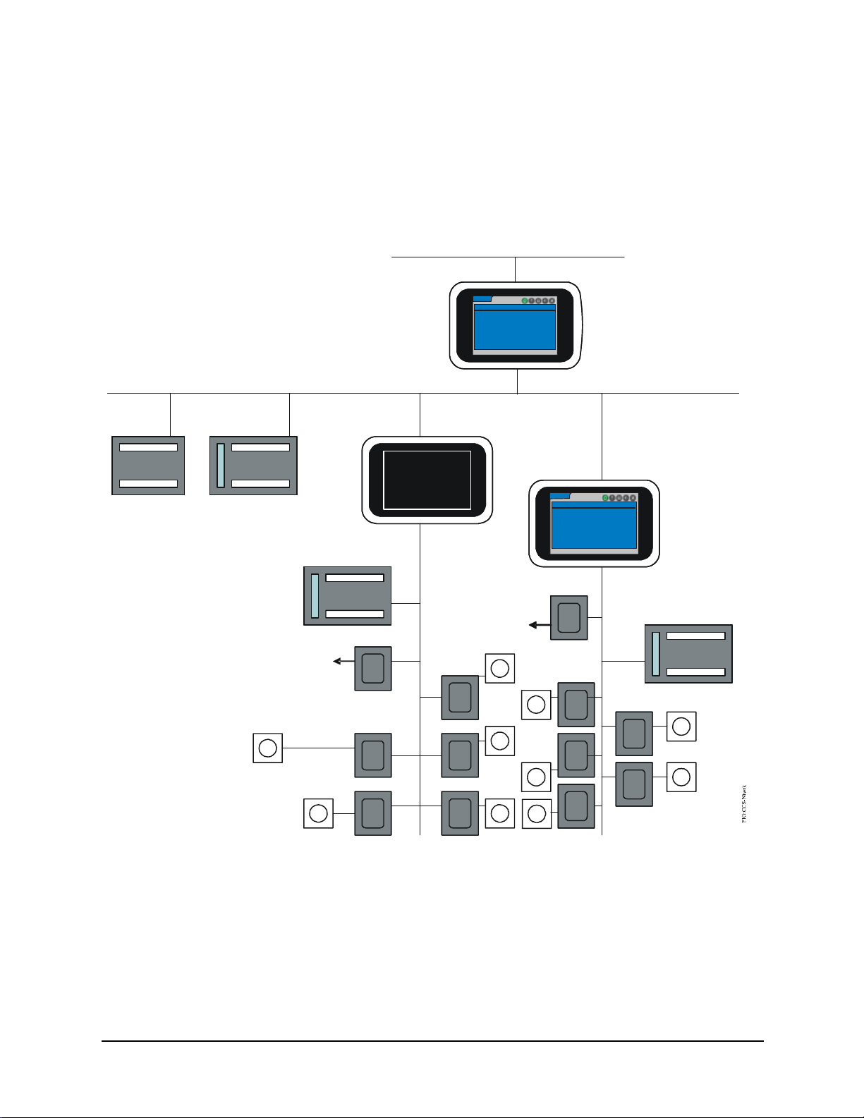
System Manager/Zone Coordinator on the Network
The System Manager and Zone Coordinator provide User Interfaces (UIs) to the
devices in the YCCS network. The display units typically install in a main equipment
or control room, and connect to the Transmission Control Protocol/Internet Protocol
(TCP/IP) Ethernet network or the Master-Slave/Token-Passing (MS/TP) Bus. You can
access a Coordinator without a display from a System Manager. Figure 1 shows an
example of the YCCS network.
TCP/IP Ethernet
System Manager
LC-SMU-0
Thursday, May 8, 2008 5:23:44 PM
Outdoor Air Temperature: 63.1 Deg F
Software Revision: 1.0.2445
System Bus (MS/TP)
I/O Module
Constant Volume
Rooftop Controller
Zone Sensors
COBP Rooftop Controller
Bypass Controller
Zone Controllers
SA Bus
Zone Bus
(MS/TP)
Zone Coordinators
LC-ZCU-10
Thursday, May 8, 2008 5:23:44 PM
Zoning System Status:
Outdoor Air Temperature:
Software Revision: 1.0. 2445
Bypass Controller
Zone Sensors
Off
68.3 Deg F
COBP Rooftop
Controller
Zone Controllers
Zone Sensors
Figure 1: Example of YCCS Network with System Manager and Zone Coordinators
System Manager/Zone Coordinator User’s Manual 7
Page 8

428516-YUM-B-0908
System Configuration
Components of the YCCS self configure as they come online. The system requires no
database commissioning or programming – the System Manager detects all Coordinators on the network and displays them to the user. As the Zone Coordinator comes
online to the Zone Bus network, it automatically discovers each zone and zone controller, then displays them to the user. A relearn function updates which devices are
online to the Zone Bus and System Bus. During the relearn process, groups and schedules that contain any of the removed devices are also updated.
User Interface Overview
The System Manager and Zone Controller each consist of a colored Liquid Crystal
Display (LCD) touch sensitive screen that you use to make all selections. No stylus
pen or mouse is required. The display contains a menu-driven interface program that is
stored in the embedded firmware. This program enables you to set system parameters,
access system information, and monitor and control connected equipment. These operations are available from five screen types that use a common layout. The five types
are the Home screen, Alarm screen, Summary screen, Schedule screen, and Setup
screen. When you select a screen by touching its icon, the icon turns green, indicating
that it is currently active.
System Startup
When the System Manager/Coordinator is powered on, the user interface displays a
splash screen with a progress bar to indicate the status of the startup. At this point, the
Alarm LED in the upper right corner of the unit is red. Seconds later, the Alarm LED
turns green. Finally, the System Manager/Coordinator displays the Home screen
(Figure 5 on page 13), which is the starting point for monitoring and controlling the
system. The entire startup sequence takes no more than a few minutes.
System Manager/Zone Coordinator User’s Manual8
Page 9

428516-YUM-B-0908
System Manager/Coordinator Menu Structure
Figure 2 is a top level flowchart of the menu structure for the System Manager/Coordinator. The menu selections are described in the following sections. See the referenced
figure numbers for a detailed flowchart of the options available under each selection.
Home Screen
Home Screen
See
Figure 5.
Alarm Screen Summary Screen
See
Figure 31.
See
Figure 38.
Schedule Screen Setup Screen
See
Figure 22.
Figure 2: Local Controller Display Menu Structure
See
Figure 11.
System Manager/Zone Coordinator User’s Manual 9
Page 10

428516-YUM-B-0908
Screen Layout
The screens that you access from the System Manager/Coordinator’s Home Screen
share a common layout and theme. Each screen has a main selection bar, title area,
main display area, help text/paging information area, and navigation area.
ZC6 - Details
Main Selection Bar
Title
Area
Zone Temperature:
Zone Current Setpoint:
Occupancy Status:
Operating Status:
Zone is Requesting:
Trend Zone Status
64.1 Deg F
62.0 Deg F
Unoccupied
Cooling
None
Base Setting:
Thermostat Al ignment:
Schedule
68.0 Deg F
Unavailable
ScrnLyt
Figure 3: System Manager Basic Screen Layout
Main Selection Bar
Each screen has the same main selection bar. It displays the job name (if defined) and
contains the primary function icons that you push to navigate to a particular screen.
The screens are Home, Alarm, Summary, Schedule, and Setup.
Main
Display
Area
Help Text/
Paging
Information
Area
Navigation
Area
Table 2: Icons on Main Selection Bar
Button Description
Home icon - returns the display to the Home screen.
Alarm Summary icon - displays the Alarm summary , which is a history of alarm
activity that has occurred. The alarm setup screen is also accessible from this
screen. The alarm icon blinks red when a new alarm is in the system.
Summary icon - displays the Summary screen, which provides a number of
summaries for the user, including trend data.
Schedule icon - displays the Schedule screen, which allows you to add,
delete, and view equipment schedules.
Setup icon - displays the Setup screen, which allows you to configure the
System Manager/Coordinator and define various systems.
System Manager/Zone Coordinator User’s Manual10
Page 11

428516-YUM-B-0908
Title Area
The title area shows the name of the display or edit screen and the name of the item
(for example, ZC6) that is being displayed or edited.
Main Display Area
This area contains the main content for the particular screen. The area may also
include touch buttons used to navigate or to display the editor screen for editing a particular parameter . This area may refresh, depending on what information appears. The
normal refresh time for indicating the change in a monitored value is 5 seconds or less.
Help Text/Paging Information Area
This area displays optional help text. The text helps you understand what is displayed
or how to edit a value. If the current screen is one of several pages (for example, an
alarm summary), then the text Page x of y appears in this area.
Navigation Area
This area may contain one or more navigation buttons used to reach other screens. One
of these buttons may be a Back button that, when pressed, displays the previous
screen.
System Manager/Zone Coordinator User’s Manual 11
Page 12

428516-YUM-B-0908
Enter Password Screen
The Password screen may appear when you attempt to change a value, request an addition, or make a deletion. The password requires 4 digits. Once the system authenticates
your password entry, the screen that you requested appears.
Enter Operat o r p a ssword
2
1
| * * * *
4
7 8 9
3
5
6
0
Enter password
Cancel ClearOK
Figure 4: Operator Password Entry Screen
Three user password levels are available, each with some slight differences; they are
Default, Operator, and Administrator.
Table 3: Three User Password Levels
Level Description
Default No login is required for this level.
Users can view any information. The local UI ass ume s th is level if no user
is logged in. The remote UI supports this level via the Guest account.
Operator Requires login with an Operator account.
Allows the user to modify almost everything (except those reserved for the
Administrator level.)
Administrator Requires login with the Administrator password.
Users can do the same actions as Operator users; plus, change
passwords, restore configuration data, relearn the System or Zone bus,
and disable the security feature.
FIG:EntrOpPWd
System Manager/Zone Coordinator User’s Manual12
Page 13

428516-YUM-B-0908
Default Passwords Provided
Several default passwords are defined from the factory. Each is listed as follows:
Table 4: List of Default Passwords
User Name Default
Password
Guest <blank> View only Remote UI only
Operator 1111 Modify all (except
Admin 2222 All privileges Local and remote UI
Privileges Av ailable at:
Local and remote UI
password)
Home Screens
The Home screen appears when you first activate the System Manager or Zone Coordinator by touching its screen. This screen indicates the name and type of device, the
current date and time, the software revision, and the outdoor air temperature. The Zone
Coordinator Home Screen also shows Zone System Status. After 10 minutes of touch
screen inactivity, the local UI times out, the user is logged out, and the screen goes to
the Home screen. After 5 more minutes of inactivity (15 minutes total), the screen
turns black.
System Manager Home Screen
YK-SMU-0
Thursday, May 8, 2008 5:23:44 PM
Outdoor Air Temperature: 63.1 Deg F
Software Revision: 1.0.2445
Zone Coordinator Home Screen
YK-ZCU-10
Thursday, May 8, 2008 5:23:44 PM
Zoning System Status:
Outdoor Air Temperature:
Software Revision: 1.0.2445
Off
68.3 Deg F
Figure 5: Home Screens - System Manager and Zone Coordinator
T able 5 indicates the varied information for displaying the outdoor air temperature and
zone system status on the Home screen. The current date, current time, outdoor air
temperature, and zone system status values refresh.
Table 5: Contents of Home Screen Display
Type of Information Status What is Displayed
Outdoor Air Temperature Reliable Current outdoor air temperature with uni ts are shown
Problem with
Sensor
Offline Change-over Bypass (COB), Constant Volume (CV), or
Unavailable Unavailable
Zoning System Status Online COB or VAV RTU status
Offline COB or VAV RTU Offline
Sensor Problem
Variable Air Volume (VAV) Rooftop Unit (RTU) Offline
FIG:HmeScrn
System Manager/Zone Coordinator User’s Manual 13
Page 14

428516-YUM-B-0908
Display and Navigation Screens
Display and Navigation screens allow you to navigate through the system. By pressing
the appropriate button, you find the information or reach the data input screen you
need. Figure 6 is an example of a navigation screen. Table 6 describes a set of navigation buttons that may appear on any screen.
YK-SMU-0 - Setup
System Manager
Systems
Auxiliary Points
Figure 6: Example of a Navigation Screen (System Manager Setup)
Table 6: Buttons Available on Navigation Screens
Button Description
Option button - changes the display to reflect this option.
<Option>
Back button - returns the display to the previous screen.
Page Down button - displays the next page of information on this screen.
Page Up button - displays the previous page of information on this screen.
System Manager/Zone Coordinator User’s Manual14
Page 15

428516-YUM-B-0908
Data Entry Screens
Data Entry screens on the System Manager/Coordinator enable you to perform operations such as entering setup parameters, selecting from a list of options, and specifying
time schedules. Figure 7 is an example of a screen where you can enter a scheduled
occupancy time. Other data entry screens display a full keyboard. T able 7 describes the
buttons that may appear in the navigation area of data entry screens.
Schedule 1 - Mon - Occupancy Time 1
Current Value:
Valid Range:
New Value:
Enter the new time value.
8:00 AM
12:00 AM to 11:29 PM
hh:mm AM
Cancel ClearOK
2
1
5
4
7 8 9
0
AM
3
6
PM
Figure 7: Example of a Data Entry Screen (Occupancy Time 1 Screen)
Table 7: Buttons Available on Navigation Area of Data Entry Screens
Button Description
OK button - performs the desired action.
OK
FIG: OccTme
Cancel button - returns the display to the previous screen (no action is taken).
Cancel
Clear button - removes the data entry made in the New Value field, so that you
Clear
can enter a different value.
Back button - returns the display to the previous screen.
System Manager/Zone Coordinator User’s Manual 15
Page 16

428516-YUM-B-0908
Remote User Interface
The System Manager/Coordinator includes a remote user interface option allowing
you to access the device remotely using Microsoft® Internet Explorer® Web browser
on your computer. You simply enter the IP address of the System Manager/Coordinator on the address bar of the browser (for example, http://169.254.13.8). A dialog box
then displays, asking you to specify a valid user name and password (Figure 8).
Figure 8: Specifying User Name and Password in Browser
Most operations available locally at the System Manager/Coordinator are also
available when you log on remotely. The differences between the remote UI and
the local UI include the following:
• The remote UI requires you to log in with a user name and password. You can
also use the default Guest account, which does not require a password and
provides view-only access to the system. The Guest access level is the
equivalent of a local user prompting the UI by pressing the touch screen.
• You can disable remote system access; see Enabling (or Disabling) the Remote
User Interface.
• You cannot disable the use of security on the remote UI.
• The remote UI time-out due to user inactivity does not log you out; remote UI
log out only occurs when you close the browser.
• The data refresh rate of the remote UI is between 5 and 10 seconds.
• The remote UI does not display the numeric keypad because you use the
computer keyboard to enter values into parameter fields or the mouse to select
from drop-down dialog boxes.
• The remote UI does not use the Back Arrow or the Up/Down Arrow buttons;
you use the browser’s Back button to display the previous screen and the scroll
bar to move up and down the screen.
System Manager/Zone Coordinator User’s Manual16
Page 17

428516-YUM-B-0908
Note: The user name and password screen in Figure 8 may also appear whenever
you are logged on to the System Manager/Coordinator and access an
operation, which requires user authentication such as changing your
password. After you enter your password, you do not need to enter it again
during the session, unless you request an operation that requires a higher
level password.
Note: All screen representations in this document reflect how they appear at the
display, not how they appear at the remote interface.
Alarms and Alarm Priorities
The System Manager and Zone Coordinator monitor the status of equipment on the
network and report an alarm whenever they detect a problem has occurred such as an
offline condition. The following information is gathered for each alarm:
• Name of the device the alarm is associated with
• Alarm condition
• Date and time when the condition occurred
• Suggested user action
• Priority of alarm, which can be one of the following:
• Service - service whenever convenient
• Service Priority - service is required as soon as possible
• Critical - service is required immediately
Types of Alarms
The Zone Coordinator generates an alarm for each new problem condition, such as:
• Offline transitions of the COB or VAV Rooftop Unit (R TU) Controller, Bypass
Damper Controller and Zone Controllers on its Zone Bus
• Online transitions of the COB or VAV RTU Controller, Bypass Damper
Controller and Zone Controllers on its Zone Bus
• Mechanical equipment problems detected by a COB or VAV RTU Controller
Similarly, the System Manager generates an alarm for:
• Offline transitions of the COB or VAV RTU Controller, IOM Controllers and
Coordinators on its System Bus
• Online transitions of the COB or VAV RTU Controller, IOM Controllers and
Coordinators on its System Bus
• Mechanical equipment problems detected by a CV RTU, COB RTU or VAV
RTU Controller
System Manager/Zone Coordinator User’s Manual 17
Page 18

428516-YUM-B-0908
Buffer Limitation
The Zone Coordinator holds the last 50 alarms in memory, whereas the System Manager keeps the last 150 alarms. When the buffer limit is reached, the newest alarm
replaces the oldest alarm. All alarms kept at the Coordinator are also forwarded to the
System Manager. If the Coordinator cannot forward the alarms to the System Manager,
the last 50 alarms are kept at the Coordinator, then sent within 30 seconds after communication between the two devices has been restored.
Alarm Detection
When a new alarm occurs, the Alarm icon on the display turns red and begins to blink.
Also, the Alarm LED on the upper right corner of the display turns from green to red.
The Alarm icon returns to its normal state and the Alarm LED returns to green after
you select the Alarm icon at the System Manager or Coordinator.
You can view alarms by pressing the Alarm icon from the Home screen. The most
recent alarms are listed first. After you view the alarms in the system, you can delete
them, either one at a time or all alarms at once.
Alarms can be routed to pagers, e-mail accounts, and cell phones via text messaging.
See Alarm Destinations on page 18 for details.
Alarm Destinations
The System Manager and Coordinator may send alarms to destinations such as pagers,
e-mail accounts, and cellular phones with text messaging systems. By default, the System Manager or Coordinator routes any critical alarm to these destinations, but only if
you have configured the destinations. An analog telephone line and a System Manager
or Zone Controller with an internal modem is required for sending alarms to pagers.
An Ethernet connection is required for sending alarms to e-mail accounts and text
messaging systems. A text messaging system is any software application that routes
text messages to cellular phones that support the Short Message Service (SMS) protocol. To increase alarm coverage, you may choose all three alarm destinations on a single System Manager and Coordinator.
The following is an example of an alarm sent to an alarm destination:
6/5/2008 1:04:28 AM ZC7 On-line 189 Communications Restored - Service
Pagers
The System Manager or Coordinator can send alarms to paging devices. When a critical alarm occurs, the internal modem in the device uses the pager configuration parameters to establish communication with the paging system. The device passes the alarm
to the paging system, then routes it to the pager . The time required for the alarm text to
reach the pager depends on several factors, including the speed and reliability of the
paging service.
E-mail Accounts
The System Manager or Coordinator can send alarms to e-mail accounts. When a critical alarm occurs, the device constructs a message with an e-mail format, then sends it
System Manager/Zone Coordinator User’s Manual18
Page 19

428516-YUM-B-0908
over the active Internet connection to the Simple Mail Transfer Protocol (SMTP)
server using the configured e-mail destination parameters. The SMTP server passes
the message into the e-mail account specified. The time required for the alarm text to
reach an e-mail Inbox depends on several factors, which include the speed and availability of the e-mail server.
Text Message s
The System Manager or Coordinator can send alarms to cellular phones that use the
SMS protocol. When a critical alarm occurs, the device constructs a message with an
SMS format, then sends it over the active Internet connection to the SMS server using
the configured text message destination parameters. The SMS server sends the message to the subscriber’s cellular phone account. The time required for the alarm text to
reach a cellular phone depends on several factors, including the speed and availability
of the service provider.
Zones, Groups, and Members
A Zone is an area of the building where temperature is under the control of a single
Zone Controller. A small office, classroom, warehouse, or gymnasium can be considered one zone.
A Group is a collection of zones that operate on the same schedule or temporary occupancy state. Each group can support up to 24 zones for COB R TU systems or 32 zones
for VAV RTU systems. Each Coordinator can control up to 4 groups.
Lastly, a Member is something you can schedule, which can be a Group, CV RTU, or
IOM output point. The Member List is the screen that shows the currently defined
members.
Event Scheduling
You can define up to 24 event schedules at the System Manager and up to 4 event
schedules on the Zone Coordinator, if the Zone Coordinator is not reporting to a System Manager. Each schedule consists of a unique schedule name and a pair of two
occupied times and two unoccupied times for each day of the week. Each schedule
also has one or more members. A member is something that can be scheduled.
The last commanded state by a schedule for a particular day rolls over into the next
day (that is, remains the same) until the next commanded state for the new day occurs.
If the Coordinator reports to a System Manager, the Coordinator scheduling is not
used. In this case, the System Manager defines and executes all Coordinator schedules.
Temporary Occupancy Override
Temporary Occupancy Override allows you to force a group of zones into a temporarily occupied state for a period of time, called the time-out delay. You can do this from
the Zone Details screen or by pushing the temporary occupancy button on the thermostat. This action causes the zone, and all other zones in the same Group, to become
temporarily occupied together. The system ignores all occupancy schedules for these
zones during the time-out period. Once the time-out delay expires, the zones return to
their normal occupancy schedule.
System Manager/Zone Coordinator User’s Manual 19
Page 20

428516-YUM-B-0908
You can also force a single schedule, or all schedules, into the temporary occupancy
state from the UI. This action places all members of the schedule into temporary occupancy. Members of the schedule can be a Group of zones or one or more CV RTUs.
Again, when the time-out period expires, the members return to their normal occupancy schedule.
You can change the temporary occupancy time-out delay. Its range is from 15 to 240
minutes, with a default value of 120 minutes. You can also cancel temporary occupancy at any time from the UI.
To indicate which schedules (if any) are temporarily occupied, view the Schedules
Summary on the System Manager or Coordinator. The Zone Status screen indicates
whether a particular zone is temporarily occupied.
All Schedules - Temporary Occupancy
This option places all schedules under temporary occupancy . This function is the same
as if just one schedule was under temporary occupancy . The same duration applies: 15
to 240 minutes.
Exception Schedules
You can add exception schedules throughout the year to accommodate holidays and
other periods of time that require different scheduling. Each exception schedule can be
for a single or reoccurring event, such as once every year. The exception replaces the
complete weekly schedule for the day it is active. Two sets of occupied and unoccupied times can be defined per exception schedule.
Global and Instant Shutdown
The Global Shutdown function shuts down the entire system from the System Manager. This command shuts down all Coordinators and CV RTUs that report to the System Manager. An enable function is also available to re-enable the entire system.
The Instant Shutdown function shuts down a single Coordinator, CV RTU, or IOM.
Shutting down a coordinator also shuts down all of its zones. An enable function is
also available to re-enable a single system.
Trend Data Collection
The System Manager and Coordinator keep records of the changing values of points in
the system. You can view these values on a Trend report. The System Manager or
Coordinator collects one sample every 15 minutes over the past 72 hours for the following values:
• Zone temperature
• Supply or discharge air temperature
• Return air temperature
• Outside air temperature
System Manager/Zone Coordinator User’s Manual20
Page 21

428516-YUM-B-0908
The System Manager and Coordinator also collect samples for the last 10 changes of
the following outputs:
• RTU fan status (On/Off)
• Cool1 to Cool4 (On/Off)
• Heat1 to Heat3 (On/Off)
You can view this data in tabular format sorted by time and date, with the most current
samples listed first. The data that is displayed for each sample includes:
• Time and Date
• Trended value
• Units (if the trended value is an analog value)
The trend information is current at the time you requested the data. The System Manager or Coordinator replaces old trend data with the newest data as it becomes available. The trend data cannot be printed or exported. Also, the data does not refresh
dynamically as it is viewed.
Display Units
The user interface can display data using the English or Metric format. Table 8 shows
the analog value units. These units apply wherever the value is displayed or modified.
You can specify which system of units to use for the site; see Selecting Display Units
on page 33.
Table 8: Display Units on User Interface
Type English Units Metric Units No. of Decimal Places
CO
2
Damper Position %%0
Pressure in wc Pa 2 for in wc
Relative Humidity %%0
Temperature Deg F Deg C 1
Time hh:mm AM or PM hh:mm AM or PM n/a
ppm ppm 0
0 for Pa
System Manager/Zone Coordinator User’s Manual 21
Page 22

428516-YUM-B-0908
Maintenance Procedures
The System Manager/Zone Coordinator includes the following maintenance procedures available to the operator:
• Backup/Restore Configuration - copies the existing configuration (or restores a
backed up configuration) using a connected Universal Serial Bus (USB) drive.
• Restore Factory Settings - replaces the configuration parameters currently
stored in the System Manager/Zone Coordinator with the original factory
defaults.
• Relearn Connected Devices - removes any offline Coordinators, CV RTUs, or
IOMs at the System Manager or zones at the Coordinator. If a device comes
back online later, it reappears in the device summary.
• Restart System Manager/Zone Coordinator - performs a general restart of the
device.
System Manager/Zone Coordinator User’s Manual22
Page 23

428516-YUM-B-0908
Detailed Procedures
Basic Procedures
Basic procedures include waking up the display, entering your password, and logging
on/logging off the remote user interface.
Waking up the Display
To wake up the System Manager/Coordinator when its display is dark, simply press
your finger to the display. The Home screen appears (Figure 5 on page 13). The display remains active until 10 minutes of no user activity. After 10 minutes, you are
logged off automatically and the Home screen returns. Then, after another 5 minutes
of inactivity, the screen goes to sleep (goes dark).
Entering Your Password
To enter your password:
1. Use the number keypad on the display to enter your four digit password
(Figure 9). The password screen displays whenever you attempt an operation
that requires user authentication. Asterisks appear as you select each number . If
you type an incorrect number, press Clear, then reenter the full password.
Enter Operator password
2
1
| * * * *
4
7 8 9
Enter password
Cancel ClearOK
3
5
6
0
Figure 9: Operator Password Entry Screen
2. Press OK to submit your password. The screen you requested appears.
FIG:Entr OpPWd
System Manager/Zone Coordinator User’s Manual 23
Page 24

428516-YUM-B-0908
Logging On the Remote User Interface
To log on the remote user interface:
1. Open your Internet browser and type the IP address of the System Manager/
Coordinator in the address bar. Example:
http://192.254.12.3
2. Press Enter. A dialog box then displays prompting for a valid user name and
password (Figure 10).
Figure 10: Specifying User Name and Password in Browser
3. Type your user name and password and click OK. The Home screen of the
System Manager/Coordinator appears.
Logging Off the Remote User Interface
T o log of f the remote user interface, simply close your browser. There is no log off button or option available.
Note: The remote user interface does not timeout the user based on inactivity.
The session is active until the browser displays a different Web page or
you close the browser.
System Manager/Zone Coordinator User’s Manual24
Page 25

428516-YUM-B-0908
Setup Procedures
Setup procedures include:
• Setting date and time parameters
• Changing the administrator or operator password
• Enabling/disabling the password requirement and remote user interface
• Setting up the modem
• Specifying Ethernet settings
• Selecting display units
• Calibrating the touch screen
• Specifying system manager name, zone coordinator name, and job name
Figure 11 is a flowchart of the Setup menu structure for the System Manager and Zone
Coordinator. These menu selections are described in the sections that follow.
Setup
Change
Operator
Password
Change
Administrator
Password
Enable/Disable
Security (Pass w o rd)
Enable/Disable
Remote User
Interface
• Daylight Savings Time
• Current Date
• Current Time
• Time Zone
• Time Display
• DHCP Enabled
• Obtain DNS Address
Automatically
• Ethernet MAC Address
• Computer Name
• Domain Name
• IP Address
• IP Mask
• IP Router Address
• 1st DNS Server IP Address
• 2nd DNS Server IP Address
Security
(password)
Time
Management
Ethernet
Setup
Job Name
Note:
If you perform Zone Coordinator setup from a System Manager, some
selections are not available because they are under the control of the System
Manager or are operations only done locally at the Coordinator. They include
Time Management, Disp l ay Se t up, Alarm Setup, Security ( Pa ssw ord), and Job
Name.
System
Manager
(See following Note.)
Display
Setup
Modem
Setup
System
Manager/
Coordinator
Name
Zone
Coordinator
Calibrate Touch
Screen
• Display Units
• Language
• Allow Incoming Connections
• Baud Rate
• Wait for Dial Tone Before Dialing
• Extra Initialization Commands
FIG:StupFlw
Figure 11: Setup Options - Menu Structure
System Manager/Zone Coordinator User’s Manual 25
Page 26

428516-YUM-B-0908
Setting Date and Time Parameters
To set date and time parameters:
1. From the Home screen, press the Setup icon. The System Manager Setup or
Coordinator Setup and Status screen appears.
2. For a System Manager, press the System Manager button. The System
Manager Setup screen appears.
For a Coordinator, press the Coordinator button. The Coordinator Setup screen
appears.
3. Press the Time Management button. The Time Management screen appears.
Time Management
Dayl ight Savings Time:
Current Date:
Time Display:
Select value to modify.
Enabled
May 6, 20 08
12-Hour
Format
Tim e Zone:
Current Time:
Central
12:47 PM
Figure 12: Time Management Screen
4. Press the button for the time parameter you want to change. The button label
describes the current setting. When you press the button, the appropriate screen
appears allowing you to change the value. Table 9 lists these parameters and
their ranges or possible selections.
FIG:TmeMgtScrn
Table 9: Time Management Parameters
Parameter Parameter Range/Selections
Current Date Month: January to December
Current Time 12:00 AM to 12:00 PM
Daylight Savings Time Enabled or Disabled
Time Display 12-hour format or 24-hour format
Time Zone Eastern, Central, Mountain, Pacific
Date: 1 to 31
Year: 2001 to 2099
System Manager/Zone Coordinator User’s Manual26
Page 27

5. Make the time parameter changes and press OK. The Time Management
screen returns, reflecting the changes you made.
Changing the Administrator or Operator Password
To change the administrator or operator password:
1. From the Home screen, press the Setup icon. The System Manager Setup or
Coordinator Setup and Status screen appears.
2. For a System Manager, press the System Manager button. The System
Manager Setup screen appears.
For a Coordinator, press the Coordinator button. The Coordinator Setup screen
appears.
3. Press the Security (password) button. The Security/Password Setup screen
appears.
4. To change the administrator password, press the Change Administrator
Password button. If you are not currently logged in as the Administrator, the
Enter Administrator Password screen appears. Enter the Administrator
password to continue. After the password is verified, the Change Administrator
Password screen appears.
428516-YUM-B-0908
To change an operator password, press the Change Operator Password button.
If you are not currently logged in as the Administrator, the Enter Administrator
Password screen appears. Enter the Administrator password to continue. After
the password is verified, the Change Administrator Password screen appears.
Change Operator Password
2
New Password:
Confirm Password:
1
|
4
7 8 9
3
5
6
0
Enter new 4 digit password.
Cancel ClearOK
FIG:Chng Pwd
Figure 13: Password Definition Screen
System Manager/Zone Coordinator User’s Manual 27
Page 28

428516-YUM-B-0908
5. Use the number keypad to specify a new password. Use any combination of 4
digits. Press the Clear button if you need to erase the digits and start over.
As you enter the password, asterisks appear in the New Password field.
6. To confirm, reenter the new password in the Confirm Password field.
7. Press OK to submit the new password. The Security/Password Setup screen
returns.
Enabling (or Disabling) Password Security
To enable (or disable) password security:
Note: This function is only available at the System Manager (or Coordinator).
You cannot perform this procedure from the remote user interface.
1. From the Home screen, press the Setup icon. The System Manager Setup or
Coordinator Setup and Status screen appears.
2. For a System Manager, press the System Manager button. The System
Manager Setup screen appears.
For a Coordinator, press the Coordinator button. The Coordinator Setup screen
appears.
3. Press the Security (password) button. The Security/Password Setup screen
appears.
4. Press the Security (Password) button. The Security (Password) screen appears.
Security (Password)
Curent Value:
Enabled
New Value:
Disabled
CancelOK
Figure 14: Security (Password) Screen
FIG:P wdEna
System Manager/Zone Coordinator User’s Manual28
Page 29

5. To disable password security when the password requirement is currently
enabled, press OK.
To enable password security when the password requirement is currently
disabled, press OK.
The Security/Password Setup screen returns, indicating the password security
change you made.
Enabling (or Disabling) the Remote User Interface
To enable (or disable) the remote user interface:
Note: This function is only available at the System Manager (or Coordinator).
You cannot perform this procedure from the remote user interface.
1. From the Home screen, press the Setup icon. The System Manager Setup or
Coordinator Setup and Status screen appears.
2. For a System Manager, press the System Manager button. The System
Manager Setup screen appears.
For a Coordinator, press the Coordinator button. The Coordinator Setup screen
appears.
428516-YUM-B-0908
3. Press the Security (password) button. The Security/Password Setup screen
appears.
4. Press the Remote User Interface button. The Remote User Interface screen
appears.
Remote User Interface
Curent Value:
Enabled
New Value:
Disabled
CancelOK
FIG:RmtUsrIntrfc
Figure 15: Remote User Interface Screen
System Manager/Zone Coordinator User’s Manual 29
Page 30

428516-YUM-B-0908
5. To disable the remote user interface when the interface is currently enabled,
press OK.
To enable the remote user interface when the interface is currently disabled,
press OK.
The Security/Password Setup screen returns, indicating the remote user
interface change you made.
Setting up a Modem
To set up a modem:
1. From the Home screen, press the Setup icon. The System Manager Setup or
Coordinator Setup and Status screen appears.
2. For a System Manager, press the System Manager button. The System
Manager Setup screen appears.
For a Coordinator, press the Coordinator button. The Coordinator Setup screen
appears.
3. Press the Modem Setup button. The Modem Setup screen appears.
Allow Incoming Connections:
Baud Rate:
Wait for Dial Tone Before Dialing:
Extra Initialization Commands:
Select value to modify.
Modem Setup
False
115200
True
M0
FIG:MdmScr n
Figure 16: Modem Setup Screen
System Manager/Zone Coordinator User’s Manual30
Page 31

428516-YUM-B-0908
4. Press the button for the modem parameter you want to change. The button
label describes the current setting. When you press the button, the appropriate
screen appears, allowing you to change the value. Table 10 lists these
parameters and their ranges or possible selections.
Table 10: Modem Parameters
Parameter Parameter Range/Selections
Allow Incoming Connections True or False
Note: Set to True if computers are permitted to
remotely access the unit over a dial-up
connection.
Baud Rate 9600; 19200; 38400; 57600; 115200
Wait for Dial Tone before Dialing True or False
Extra Initialization Commands Enter modem initialization commands, up to 30
characters.
1. A full keyboard screen appears allowing you to enter the characters of the command. Press OK
to save the character set. The Modem Setup screen retur ns, in dicati ng the mo dem in itia liza tion
string you entered.
1
5. Make the modem parameter changes and press OK. The Modem Setup screen
returns, reflecting the changes you made.
Specifying Ethernet Settings
To specify Ethernet settings:
1. From the Home screen, press the Setup icon. The System Manager Setup or
Coordinator Setup and Status screen appears.
2. For a System Manager, press the System Manager button. The System
Manager Setup screen appears.
For a Coordinator, press the Coordinator button. The Coordinator Setup screen
appears.
3. Press the Ethernet Setup button. The Ethernet Setup screen appears.
System Manager/Zone Coordinator User’s Manual 31
Page 32

428516-YUM-B-0908
4. Press the Change Values button to enable editing of the parameters. The screen
updates by displaying buttons that indicate the values you can change.
Ethernet Setup
DHCP Enabled:
Obtain DNS Address
Automatically:
Ethernet MAC
Address:
Comput er Name:
Domain Name:
Select values to modify then Apply Changes.
True
False
0-10-8d-0-e6-15
SICSDefault
Apply Changes
IP Addre ss:
IP Mask:
IP Router Address:
1st DNS Server IP
Address:
2nd DNS Server IP
Address:
192.254.6.83
255.255.252.0
192.254.6.2
10.10.13.2
10.10.15.5
Figure 17: Ethernet Setup Screen
5. Press the button for the Ethernet parameter you want to change. The button
label describes the current setting. When you press the button, the appropriate
screen appears, allowing you to change the value. Table 11 lists these
parameters and their ranges or possible selections.
FIG:EthrntScrn
Table 11: Ethernet Parameters
Parameter Parameter Range/Selections
DHCP Enabled True or False
Obtain DNS Address Automatically True or False
Computer Name
Domain Name
IP Address
IP Mask
2
2
IP Router Address
2
Enter computer name up to 15 characters
Enter domain name up to 24 characters
Enter IP address, 0 to 255 per segment
Enter IP address, 0 to 255 per segment
Enter IP address, 0 to 255 per segment
1st DNS Server IP Address Enter server IP address, 0 to 255 per segment
2nd DNS Server IP Address Enter server IP address, 0 to 255 per segment
1. A full keyboard screen appears allowing you to enter a name. Press OK to save the name. The
Ethernet Setup screen returns, indicating the name you entered.
2. This parameter is editable only when DHCP Enabled is set to False.
1
1
6. Make the Ethernet parameter changes and press Apply Changes. The Ethernet
Setup screen returns, reflecting the changes you made.
System Manager/Zone Coordinator User’s Manual32
Page 33

Selecting Display Units
To select Display units:
1. From the Home screen, press the Setup icon. The System Manager Setup or
Coordinator Setup and Status screen appears.
2. For a System Manager, press the System Manager button. The System
Manager Setup screen appears.
For a Coordinator, press the Coordinator button. The Coordinator Setup screen
appears.
3. Press the Display Setup button. The Display Setup screen appears.
YK-SMU-0 - Display Setup
428516-YUM-B-0908
Display Units:
Language:
Select value to modify.
Calibrate Touch
Imperial
English
Screen
Figure 18: Display Units Setup Screen
4. Press the Display Units button. The Display Units screen appears.
5. Press OK to change the units to the opposite of the current setting. The Display
Setup screen returns, reflecting the change you made.
Calibrating the Display
FIG:DispScrn
To calibrate the Display:
Note: Calibrate the screen when the display is not properly centered (for
example, skewed to the left or right).
1. From the Home screen, press the Setup icon. The System Manager Setup or
Coordinator Setup and Status screen appears.
System Manager/Zone Coordinator User’s Manual 33
Page 34

428516-YUM-B-0908
2. For a System Manager, press the System Manager button. The System
Manager Setup screen appears.
For a Coordinator, press the Coordinator button. The Coordinator Setup screen
appears.
3. Press the Display Setup button. The Display Setup screen appears.
4. Press the Calibrate Touch Screen button. The screen turns to white, with a
calibration instruction shown at the top.
Careful ly press and hol d finger on the
center of the target. Repeat as the tar get
moves around the screen
+
Figure 19: Calibrate Screen
5. To calibrate, carefully press and hold your finger on the center of the target.
Repeat this step as the target moves to each corner of the screen.
After calibration is complete, the System Manager/Coordinator screen returns.
FIG:CalScr n
System Manager/Zone Coordinator User’s Manual34
Page 35

Specifying System Manager/Zone Coordinator Name
_
j
To specify the System Manager or Zone Coordinator name:
1. From the Home screen, press the Setup icon. The System Manager Setup or
Coordinator Setup and Status screen appears.
2. For a System Manager, press the System Manager button. The System
Manager Setup screen appears.
For a Coordinator, press the Coordinator button. The Coordinator Setup screen
appears.
3. Press the System Manager Name or Coordinator Name button. The System
Manager Name or Coordinator Name entry screen appears.
System Manager Name
428516-YUM-B-0908
Current System Name:
New System Name:
2
1
q
a s d f
caps z
Enter System Name up to 24 characters.
3 4
w e
r
x c
YK-SMU-0
|
5
t
g
v
6
y
h
b
Cancel ClearOK
7
u
n
8
i
k l ?
m
0
p
Space
Backspace
/
=
-
.
9
o
Figure 20: System Manager Name Entry Screen
4. Use the keyboard screen to enter a name for the System Manager or
Coordinator. A maximum of 24 characters are allowed.
5. Press OK to save the name. The System Manager/Coordinator Setup screen
returns, reflecting the change you made. The System Manager and Coordinator
names are used on the titles of many screens in the user interface.
FIG: SysNme
System Manager/Zone Coordinator User’s Manual 35
Page 36

428516-YUM-B-0908
/
_
j
Entering Job Name
To enter a job name:
1. From the Home screen, press the Setup icon. The System Manager Setup or
Coordinator Setup and Status screen appears.
2. For a System Manager, press the System Manager button. The System
Manager Setup screen appears.
For a Coordinator, press the Coordinator button. The Coordinator Setup screen
appears.
3. Press the Job Name button. The Job Name screen appears.
Johnson Medical
Job Name
Current Job Name:
New Job Name:
2
1
q
a s d f
caps z
Enter Job Name up to 24 characters.
3 4
w e r
Johnson Medical
|
x c
5
6
y
t
g
h
v
b
Cancel ClearOK
7
u
n
8
i
k l ?
m
0
p
Space
Backspace
=
-
.
9
o
Figure 21: Job Name Entry Screen
4. Use the keyboard screen to enter a job name. A maximum of 24 characters are
allowed.
5. Press OK to save the name. The System Manager or Coordinator Setup screen
returns, reflecting the change you made. The Job Name is shown in the upper
left corner of all screens in the user interface.
FIG: JobNme
System Manager/Zone Coordinator User’s Manual36
Page 37

Scheduling Procedures
Scheduling procedures include:
• Adding a schedule
• Deleting a schedule
• Adding a member to a schedule
• Deleting a member from a schedule
• Configuring temporary occupancy
• Beginning temporary occupancy
• Ending temporary occupancy
• Adding temporary occupancy to all schedules
Note: If the Coordinator is under the control of the System Manager, its schedules
are not accessible. In this case, the message Please access Schedules at the
System Manager display appears when you press the Schedule icon on
the Coordinator Home screen.
428516-YUM-B-0908
System Manager/Zone Coordinator User’s Manual 37
Page 38

428516-YUM-B-0908
Figure 22 is a flowchart of the Schedule menu structure for the System Manager.
These menu selections are described in the sections that follow. A schedule option is
also offered under the Setup menu.
• Mon – Occ/Unocc
• Tues – Occ/Unocc
• Wed – Occ/Unocc
• Thurs – Occ/Unocc
• Fri – Occ/Unocc
• Sat – Occ/Unocc
• Sun – Occ/Unocc
Members
Schedule
Member List
Group 2Group 1
Group n ...
Add Schedule
Schedule
Name
New Schedule
Name
Add Member
System Schedules
Occupancy
Exceptions
Schedule Exception
and
Holiday Schedules
Add
Exception
Temporary
Occupancy All
Schedules
End
Exceptions
Begin
Occupancy
End
Occupancy
Delete All
Temporary
Occupancy
Occupancy
System
Manager
Temporary
Occupancy
• Temporary
Occupancy Time
Delete
Schedule
Begin
Setup
Zone
Coordinator
Setup
• Begin Date
• End Date
• Occ Time
• Unocc Time
• Occ Time #2
• Unocc Time #2
Figure 22: Schedule Options - Menu Structures
FIG:SysSummFlw
System Manager/Zone Coordinator User’s Manual38
Page 39

Adding a Schedule
y
To add a schedule:
1. From the Home screen of the System Manager, press the Schedule icon. The
Schedules screen appears.
2. Press the Add Schedule button. The Daily Schedules screen appears. A
weekday schedule is presented with default occupancy and unoccupancy times
of 8:00 AM and 5:00 PM, respectively.
Email Setup
Schedule 1 - Daily Schedules
428516-YUM-B-0908
Occ = 08:00:00 AM Unocc = 05:00:00 PM
Mon
Occ = 08:00:00 AM Unocc = 05:00:00 PM
Tue
Occ = 08:00:00 AM Unocc = 05:00:00 PM
Wed
Occ = 08:00:00 AM Unocc = 05:00:00 PM
Thu
Members
Schedule
Name
Figure 23: Daily Schedules Screen
Exceptions
Occ = 08:00:00 AM Unocc = 05:00:00 PM
Fri
Sat
Sun
Te mp or a ry
Occupancy
Delete
Schedule
SchedScr n
FIG:Dal
System Manager/Zone Coordinator User’s Manual 39
Page 40

428516-YUM-B-0908
3. Press the day of week button to define its occupied and unoccupied times. The
configuration screen for this schedule day appears.
Email Setup
Schedule 1 Schedule - Mon
Touch the Occupied/Unoccupied time to change:
Occ Time
08:00:00 AM
Occ Time
- - - -
Select command to modify.
Copy to
Mon-Fri
Unocc Time
05:00:00 PM
Unocc Time
- - - -
Copy to
all days
Figure 24: Example Schedules Screen for Monday
4. Enter up to two pairs of occupied/unoccupied times for this day of the week.
5. Once you have defined the occupied/unoccupied times, you can copy these
times to the rest of the weekdays of the week. To do so, press the Copy to
Mon-Fri button. Or, if you want to copy these times for all days of the week
including the weekend, press the Copy to All Days button.
FIG:MonSch edScrn
6. Press OK to save your changes and return to the Daily Schedules screen. The
changes you made are indicated.
System Manager/Zone Coordinator User’s Manual40
Page 41

Deleting a Schedule
y
To delete a schedule:
1. From the Home screen of the System Manager, press the Schedule icon. The
Schedules screen appears.
2. Select the Schedule you wish to delete; that schedule’s Daily Schedule appears.
Email Setup
Schedule 1 - Daily Schedules
428516-YUM-B-0908
Occ = 08:00:00 AM Unocc = 05:00:00 PM
Mon
Occ = 08:00:00 AM Unocc = 05:00:00 PM
Tue
Occ = 08:00:00 AM Unocc = 05:00:00 PM
Wed
Occ = 08:00:00 AM Unocc = 05:00:00 PM
Thu
Members
Schedule
Name
Exceptions
Occ = 08:00:00 AM Unocc = 05:00:00 PM
Fri
Sat
Sun
Te mp or a ry
Occupancy
Delete
Schedule
Figure 25: Delete Schedule Screen
3. Press the Delete Schedule button to remove the currently shown schedule from
the System Manager. The schedule is deleted, and the Schedules screen
returns, indicating the schedule has been removed.
SchedScr n
FIG:Dal
System Manager/Zone Coordinator User’s Manual 41
Page 42

428516-YUM-B-0908
FIG:SlctMembr
Adding a Member to a Schedule
To add a member to a schedule:
1. From the Home screen of the System Manager, press the Schedule icon. The
Schedules screen appears.
2. Select the schedule to which you want to add members; that schedule’s Daily
Schedules screen appears.
3. Press the Members button. The Member List for this schedule appears.
4. Press the Add Member button. The Select New Member screen for this
schedule appears. This screen shows all schedulable items that are not already
members of this schedule, even if they are in another schedule.
Select New Member for Schedule 1
Group 1
Group 2
SA-FAN
CV RTU 24
Select a member to add/move into this schedule
Add All
Email Setup
Current Schedule:
None
Current Schedule:
None
Current Schedule:
None
Current Schedule:
None
Page 1 of 2
Figure 26: Select New Member Screen
5. Press on a member button to add or move the member to this schedule. Press
Yes to confirm. The member is added (or moved) and disappears from this
screen.
If you want to add or move all members into this schedule, press the Add All
button.
6. Press the Back button and verify that the member has been added to schedule.
System Manager/Zone Coordinator User’s Manual42
Page 43

Deleting a Member from a Schedule
To delete a member from a schedule:
1. From the Home screen of the System Manager, press the Schedule icon. The
Schedules screen appears.
2. Select the schedule from which you want to delete a member; that schedule’s
Daily Schedules screen appears.
3. Press the Members button. The Member List for this schedule appears. If this
list is empty, then there are no members to delete. (Each added member gets
added to this list.)
Email Setup
Schedule 1 Member List
Group 1
428516-YUM-B-0908
Select a member to delete from this schedule
Add Member
Figure 27: Delete Member Screen
4. Press on a member button to select it for deletion. The Delete Group x from
Schedule x screen appears.
5. Select Delete Member to remove it. Press Yes to confirm. The Member List
appears and is now refreshed, indicating the member is no longer in the list.
FIG:DeltMbr
System Manager/Zone Coordinator User’s Manual 43
Page 44

428516-YUM-B-0908
Adding an Exception Schedule
To add an exception schedule:
1. From the Home screen of the System Manager, press the Schedule icon. The
Schedules screen appears.
2. Select the schedule to which you want to add an exception. The Daily
Schedules screen for that schedule appears.
3. Press the Exceptions button. The Exception and Holiday Dates screen for this
schedule appears.
4. Press the Add Exception button. The Properties for Exception screen appears.
Properties for Exception - May 15, 2008 through May 15, 2008
Current Value:
New Value:
Select New Reoccurs annually setting or continue to leave as is.
No
Yes
Continue
Figure 28: Properties for Exception Screen
System Manager/Zone Coordinator User’s Manual44
Page 45

428516-YUM-B-0908
5. Press Yes to create this exception and have it reoccur annually. Or click
Continue to create the exception as a one-time event. The Properties for
Exception definition screen appears.
Properties for Exception - May 16, 2008 through May 16, 2008
Begin Date
Friday, May 16, 2008
Occ Time
8:00:00 AM
Occ Time
- - - -
Select a part of the exception to modify.
Delete
Exception
Email Setup
End Date
Friday, May 16, 2008
Unocc Time
5:00:00 PM
Unocc Time
- - - -
Done
Figure 29: Properties for Exception Definition Screen
6. Press on the Begin Date and End Date buttons to specify the dates of this
exception’s start and finish.
Note: If the Begin Date you enter is after the End Date, and the exception is
reoccurring (that is, no year entered), the exception crosses the year
boundary . For example, a Begin Date of December 24 and an End Date
of January 2 starts in one year and ends in the next.
7. Press on the Occ Time and Unocc Time buttons to specify the times of when
the schedule is occupied and unoccupied.
8. After you are satisfied with the entries, press Done to save.
Setting up Temporary Occupancy Time
To set up a temporary occupancy time:
1. From the Home screen, press the Setup icon. The System Manager Setup or
Coordinator Setup and Status screen appears.
2. For a System Manager, press the System Manager button. The System
Manager Setup screen appears.
For a Coordinator, press the Coordinator button. The Coordinator screen
appears.
System Manager/Zone Coordinator User’s Manual 45
Page 46

428516-YUM-B-0908
3. Press the Temporary Occupancy Setup button. The Temporary Occupancy
Setup screen appears.
4. Press the Temporary Occupancy Time button. The Temporary Occupancy
Time screen appears.
Te mpo rary Occupancy Time
Current Value:
Valid Range:
New Value:
Enter the new time value.
120 min
15 mins - 240 mins
- - - -
Cancel ClearOK
2
1
5
4
7 8 9
0
3
6
Figure 30: Temporary Occupancy Setup Screen
5. Use the numeric keypad to enter a new temporary occupancy time. The valid
range is from 15 to 240 minutes.
6. Press OK to save your change. The Temporary Occupancy Setup screen
returns, indicating the change you made.
FIG:TempOccTime
Beginning Temporary Occupancy of a Schedule
To begin temporary occupancy of a schedule:
1. From the Home screen of the System Manager, press the Schedule icon. The
Schedules screen appears.
2. Select a schedule for temporary occupancy; the Daily Schedules screen for that
schedule appears.
3. Press the Temporary Occupancy button. The Schedule Temporary Occupancy
screen appears.
4. Press the Begin Occupancy button. Select Yes to confirm.
System Manager/Zone Coordinator User’s Manual46
Page 47

Ending Temporary Occupancy of a Schedule
To end temporary occupancy of a schedule:
1. From the Home screen, press the Schedule icon. The Schedules screen appears.
2. Select the schedule to end temporary occupancy. The Daily Schedules screen
for that schedule appears.
3. Press the Temporary Occupancy button. The Schedule Temporary Occupancy
screen appears.
4. Press the End Occupancy button. Select Yes to confirm.
Beginning or Ending Temporary Occupancy to All Schedules
To begin or end temporary occupancy for all schedules:
1. From the Home screen, press the Schedule icon. The Schedules screen appears.
2. Press the Temp Occ All Schedule button. The All Schedules Temporary
Occupancy screen appears.
3. To begin, press the Begin Occupancy button.
To end, press the End Occupancy button.
428516-YUM-B-0908
System Manager/Zone Coordinator User’s Manual 47
Page 48

428516-YUM-B-0908
Alarm Procedures
Alarm procedures include:
• Configuring a pager alarm destination
• Configuring an e-mail alarm destination
• Configuring a text message alarm destination
• Configuring alarm indicators
• Viewing an alarm summary
• Deleting alarms
Figure 31 is a flowchart of the Alarm menu structure for the System Manager. These
menu selections are described in the sections that follow.
Alarm Summary
Destination
• Pager Phone Number
• Pager Service Access Number
• Alarm Priority Required to
• Send Message to Pager
• Max Text Characters
• Databits
• Parity
• Stop Bits
Alarm
Setup
Pager
Destination
• Email Address
• SMTP Server Host
• Alarm Priority Required to
• Send Email Message
• SMTP Port
• Authentication Needed
Email
Delete All
Alarms
Text Message
Destination
• Phone Number
• Carrier
• Other Carriers Domain
• SMTP Service Host
• Alarm Priority Required to
• Sent Text Message
• SMTP Port
• Authentication Needed
Figure 31: Alarm Options - Menu Structure
Alarm
Indicators
• Alarm Priority Required to
Activate Alarm Indicators
FIG:AlmStFlw
System Manager/Zone Coordinator User’s Manual48
Page 49

Configuring Pager as Alarm Destination
To configure a pager as an alarm destination:
1. From the Home screen of the System Manager or Zone Coordinator, press the
Alarm Summary icon. The Alarm Summary screen appears.
2. Press the Alarm Setup button. The Alarm Setup screen appears.
3. Press the Pager Destination button. The Pager Setup screen appears.
Pager Setup
428516-YUM-B-0908
Pager P hone Number:
Pager Service Access Number:
Alarm Priority Required to Send
Message t o P ager:
Max Text Characters:
0
Databits:
Stop bits:
None
Parity:
7
Even
1
Figure 32: Pager Setup Screen
4. Press the button for the Pager parameter you want to change. The button label
describes the current setting. When you press the button, the appropriate screen
appears allowing you to change the value. Table 12 lists these parameters and
their ranges or possible selections.
FIG:PgrScrn
Table 12: Pager Setup Parameters (Part 1 of 2)
Parameter Parameter Range/Selections
Pager Phone Number
Pager Service Access Number
Alarm Priority Required to Send Message to Pager Select one of these options:
Max Text Characters 1-255
Enter a value up to 24 characters
Enter a value up to 24 characters
• Service, Service Priority and Critical
• Service Priority and Critical
• Critical
• None
System Manager/Zone Coordinator User’s Manual 49
1
1
Page 50

428516-YUM-B-0908
Table 12: Pager Setup Parameters (Part 2 of 2)
Parameter Parameter Range/Selections
Databits 7 or 8
Parity Even, Odd, None, Mark, or Space
Stop bits 1, 1.5, or 2
1. A full keyboard screen appears, allowing you to enter a phone number. Press OK to save the
name. The Pager Setup screen returns, indicating the number you entered.
5. Make the pager destination changes and press OK. The Pager Setup screen
returns, reflecting the changes you made.
Configuring E-mail Account as Alarm Destination
To configure an e-mail account as an alarm destination:
1. From the Home screen of the System Manager or Zone Coordinator, press the
Alarm Summary icon. The Alarm Summary screen appears.
2. Press the Alarm Setup button. The Alarm Setup screen appears.
3. Press the E-mail Destination button. The E-mail Setup screen appears.
Email Address:
SMTP Server Host:
Alarm Priority required
to send email message:
SMTP Port:
Email Setup
Email Setup
25
Authentication
Figure 33: E-mail Setup Screen
None
Needed:
Yes
FIG:EmlScrn
System Manager/Zone Coordinator User’s Manual50
Page 51

428516-YUM-B-0908
4. Press the button for the e-mail parameter you want to change. The button label
describes the current setting. When you press the button, the appropriate screen
appears, allowing you to change the value. Table 13 lists these parameters and
their ranges or possible selections.
Table 13: E-mail Destination Setup Parameters
Parameter Parameter Range/Selections
E-mail Address
SMTP Server Host Specify SMTP server as a host name (up to 30
Alarm Priority Required to Send E-mail
Message
SMTP Port 0-65535
Authentication Needed Yes or No
SMTP User Name
SMTP Password
3
3
Enter a valid e-mail address up to 30 characters
characters) or enter an IP address
Select one of these options:
• Service, Service Priority and Critical
• Service Priority and Critical
• Critical
• None
Enter SMTP User Name up to 24 characters
Enter SMTP Password up to 20 characters. After
you enter the password, its characters appear as
asterisks (*) on the setup screen.
2
1
1. A full keyboard screen appears, allowing you to enter an e-mail address. Press OK to save the
e-mail address; remember to include the @ symbol. The e-mail Setup screen returns, indicating
the address you entered.
2. A full keyboard or keypad appears, allowing you to enter the host name or IP address. Press
OK to save the name/address. The e-mail Setup screen returns, indicating the name/address
you entered.
3. This parameter appears only if Authentication Needed = Yes.
5. Make the e-mail destination changes and press OK. The E-mail Setup screen
returns, reflecting the changes you made.
Configuring Text Message as Alarm Destination
To configure a text message as an alarm destination:
1. From the Home screen of the System Manager or Zone Coordinator, press the
Alarm Summary icon. The Alarm Summary screen appears.
2. Press the Alarm Setup button. The Alarm Setup screen appears.
System Manager/Zone Coordinator User’s Manual 51
Page 52

428516-YUM-B-0908
3. Press the Text Message Destination button. The Text Message Setup screen
appears.
Email Setup
Text Message Setup
Phone Num b er :
Domain:
None
Carrier:
SMTP Server Host:
Alarm Priority Required to
Send Text Message :
SMTP Port:
Authentication
Needed::
Other
25
No
SMTP User Name:
SMTP Password:
Other Carrier’s
0.0.0.0
Figure 34: Text Message Setup Screen
4. Press the button for the text message parameter you want to change. The button
label describes the current setting. When you press the button, the appropriate
screen appears, allowing you to change the value. Table 14 lists these
parameters and their ranges or possible selections.
FIG:TxtMsgSc rn
Table 14: Text Message Setup Parameters (Part 1 of 2)
Parameter Parameter Range/Selections
Phone Number Enter text message phone number up to 24
characters
Carrier Alltel, AT&T, Nextel, Cingular, Sprint, T-Mobile,
Verizon, or Virgin Mobile
Other Carrier’s Domain
Enter domain up to 30 characters
SMTP Server Host Specify SMTP server as a host name (up to 30
characters) or enter an IP address
1
1
2
System Manager/Zone Coordinator User’s Manual52
Page 53

428516-YUM-B-0908
Table 14: Text Message Setup Parameters (Part 2 of 2)
Parameter Parameter Range/Selections
Alarm Priority Required to Send Text
Message
SMTP Port 0-65535
Authentication Needed Yes or No
SMTP User Name
SMTP Password
1. A full keyboard screen appears, allowing you to enter an e-mail address. Press OK to save the
e-mail address; remember to include the @ symbol. The E-mail Setup screen returns, indicating
the address you entered.
2. A full keyboard or keypad appears, allowing you to enter the host name or IP address. Press
OK to save the name/address. The e-mail Setup screen returns, indicating the name/address
you entered.
3. This parameter appears only if Authentication Needed = Yes.
3
3
Select one of these options:
• Service, Service Priority and Critical
• Service Priority and Critical
• Critical
• None
Enter SMTP User Name up to 24 characters
Enter SMTP Password up to 20 characters. After
you enter the password, its characters appear as
asterisks (*) on the setup screen.
5. Make the text message destination changes and press OK. The Text Message
Setup screen returns, reflecting the changes you made.
Setting Alarm Indicators
To set alarm indicators:
1. From the Home screen of the System Manager or Zone Coordinator, press the
Alarm Summary icon. The Alarm Summary screen appears.
2. Press the Alarm Setup button. The Alarm Setup screen appears.
3. Press the Alarm Indicators button. The Alarm Indicators Setup screen appears.
System Manager/Zone Coordinator User’s Manual 53
Page 54

428516-YUM-B-0908
4. Press the button for the Alarm Priority required to activate alarm indicators.
The Alarm Priority screen appears.
Alarm Priorities that Activate Alarm Indicators
Current Value:
New Value:
Select new value.
Service Priority and
Critical
Critical
None
Figure 35: Alarm Priorities That Activate Alarm Indicators Screen
5. Select from one of these options:
• Service, Service Priority, and Critical
• Service Priority and Critical
FIG:AlmPrtyScrn
• Critical
• None
6. Press OK to save the change. The Alarm Indicators Setup screen returns,
reflecting the change you made.
System Manager/Zone Coordinator User’s Manual54
Page 55

Viewing an Alarm Summary
To view an alarm summary:
1. From the Home screen of the System Manager, press the Alarm Summary icon.
The Alarm Summary screen appears.
YK-SMU-10 - Alarms
428516-YUM-B-0908
YK-ZCU-12
YK-ZCU-12
ZC9
YK-ZCU-10
Select alarm to view details.
Alarm Setup
Delete All Alarms
Offline
Online
Bypass Offline
Offline
May 12, 2008 7:09:28 AM
May 12, 2008 6:19:21 AM
May 11, 2008 4:22:16 PM
May 11, 2008 1:44:21 PM
Page 1 of 2
Figure 36: Alarm Summary Screen
The Alarms Summary lists the alarms that have been generated and not deleted.
2. To view more information for a particular alarm, press its button. The Alarm
Details screen appears.
FIG:AlmSummScrn
System Manager/Zone Coordinator User’s Manual 55
Page 56

428516-YUM-B-0908
Deleting One or All Alarms
To delete one or all alarms:
1. From the Home screen of the System Manager, press the Alarm Summary icon.
The Alarm Summary screen appears.
2. T o delete all alarms shown in the Alarm Summary, press the Delete All Alarms
button. Press Yes to confirm. All alarms are deleted, and the Alarm Summary
refreshes to indicate the removal of these alarms.
To delete just one alarm, press on the alarm you want to delete. The Alarms
detail for that alarm appears.
YK-SMU-10 - Alarms
Device:
Date/Time of Alarm:
Alarm Priority:
Action To Take:
Condition:
Select alarm to view details.
Delete Alarm
YK-ZCU-10
May 9, 2008 4:33:15 PM
Service, Service Priority and Critical
No Action
Bypass Controller Communications restored
Figure 37: Alarms Detail Screen
3. Press the Delete Alarm button. Press Yes to confirm.
The alarm is deleted from the database and the Alarms Summary returns,
indicating this alarm has been removed.
FIG;AlmSummDetl
System Manager/Zone Coordinator User’s Manual56
Page 57

428516-YUM-B-0908
Summary Procedures
Summary procedures include:
• Viewing system summaries
• Viewing trend data
Summaries shown at the System Manager include all Zone Coordinators and CV
RTUs.
Summaries shown at the Zone Coordinator include its zones.
Figure 38 is a flowchart of the Summary menu structure for the System Manager.
These menu selections are described in the following sections.
System Summaries
CV RTU
System
Details
Zone Coordinator
System
List of Zones
Trend
Trended Values
Figure 38: Summary Options - Menu Structure
FIG:SysSummFlw
System Manager/Zone Coordinator User’s Manual 57
Page 58

428516-YUM-B-0908
Viewing System Summaries
To view system summaries:
1. From the Home screen, press the Summary icon. The System Manager
Summary or Summary of Zone Controllers screen appears.
2. For a System Manager, select a Zone Coordinator by pressing its button. A
summary of the zones appears, indicating the name of each controller and the
controllers’ current status.
YK-SMU-10 - Summary
YK-ZCU-12
YK-ZCU-12
ZC9
CV-RTU 24
Select zone to view details.
More
Offline
72.1 Deg F
63.7 Deg F
Page 1 of 2
Figure 39: System Summary Screen
For more information on the zone controller, press its button; a zone controller Details
screen appears.
FIG:SummScr n
System Manager/Zone Coordinator User’s Manual58
Page 59

Viewing Trend Data
To view trend data:
1. From the Home screen, press the Summary icon. The System Manager
Summary or Summary of Zone Controllers screen appears.
2. For a System Manager, select a Zone Coordinator by pressing its button. A
summary of the zones appears, indicating the name of each controller and its
current status.
3. Select a zone controller. A Details screen appears.
4. Press the Trend button. A Trend Summary for the zone temperature appears. It
may take a few seconds for the summary to appear as the data is retrieved.
ZC6 - Zone Temperature Trend
428516-YUM-B-0908
May 12, 2008 9:45 AM
May 12, 2008 9:30 AM
May 12, 2008 9:15 AM
May 12, 2008 9:00 AM
May 12, 2008 8:45 AM
May 12, 2008 8:30 AM
May 12, 2008 8:15 AM
May 12, 2008 8:00 AM
May 12, 2008 7:45 AM
May 12, 2008 7:30 AM
May 12, 2008 7:15 AM
May 12, 2008 7:00 AM
May 12, 2008 6:45 AM
May 12, 2008 6:30 AM
May 12, 2008 6:15 AM
May 12, 2008 6:00 AM
68.4 Deg F
68.1 Deg F
69.5 Deg F
69.1 Deg F
69.8 Deg F
69.0 Deg F
69.7 Deg F
70.4 Deg F
70.3 Deg F
69.7 Deg F
70.2 Deg F
68.9 Deg F
69.0 Deg F
69.4 Deg F
69.7 Deg F
70.4 Deg F
Figure 40: Trend Summary Screen
5. Press the Back button to return to the previous screen.
Page 1 of 2
FIG:ZneTmpTrnd
System Manager/Zone Coordinator User’s Manual 59
Page 60

428516-YUM-B-0908
Zone Setup Procedures
Zone setup procedures include:
• Setting up a zone
• Editing zone name
• Viewing zone status
• Copying zone setup to all zones
• Requesting global shutdown of all zones
• Viewing device diagnostics for a zone
Figure 41 is a flowchart of the menu structure that is used to set up zones on the System Manager. These menu selections are described in the sections that follow.
Setup
Systems
Zone
Coordinator
Coordinator Setup
and Status
System
Setup
CV/COB RTU
Balance System
• Control Mode
• Discharge Air Temp Setpoint
• Discharge Air Temp Strategy
• Duct Static Setpoint
• Duct Static Setpoint Reset
• Duct Static Shutdown Limit
• Econ Damper Position for Exhaust Fan On
• Econ Damper Position for Exhaust Fan On
• Economizer Min Position
• Max DAT Setpoint Adjust
• Max Duct Static Setpoint Adjust
• Morning Warm-up
• Morning Warm-up Return Air Setpoint
• Representative Zone
• Unoccupied Heating/Cooling
Status
Zoning System
Status
CV RTU
• Control Mode
• Discharge Cooling Setpoint
• Discharge Heating Setpoint
• Min Number of Requests to
Change Mode
• Min Number of Urgent Requests
to Change Mode
• Min Time Before Changeover
• Number of Cooling Stages
• Number of Heating Stages
• Static Pressure Setpoint
Figure 41: Zone Setup Options - Menu Structure
Instant
Shutdown
VAV RTU
FIG:ZneSysStupFlw
System Manager/Zone Coordinator User’s Manual60
Page 61

Setting Up a Changeover Bypass Zone
To set up a changeover bypass zone:
1. From the Home screen, press the Setup icon. The System Manager Setup or
Coordinator Setup and Status screen appears.
2. For a System Manager, press the Systems button, then select the coordinator
that contains the zone you want to configure. The Coordinator Setup and Status
screen appears.
For a Coordinator, press the Systems button. The System Setup and Status
screen appears.
3. Press the Zones button. The Zones Setup and Status screen appears.
4. Press the Setup button. The Summary of Zone Controllers appears.
5. Select the zone. The Zone Setup screen appears.
428516-YUM-B-0908
Thermostat Warm / Cool
Temporary Occupancy
Max Damper
Position:
Heating M in Damper
Position:
Cooling Min Damper
Position:
Select value to modify.
Edit Zone Name
Voting:
Adjust:
Input:
ZC6 - Zone Setup
Enabled
Enabled
Enabled
95.0%
20.0%
20.0%
Zone Status
Heating Unocc Setpoint:
Heating Occ Setpoint:
Cooling Occ Setpoint:
Cooling Unocc Setpoint:
Copy Zone Setup to
All Other Zones
62.0 Deg F
68.0 Deg F
72.0 Deg F
78.0 Deg F
FIG:ZneStu p
Figure 42: Zone Setup Screen
System Manager/Zone Coordinator User’s Manual 61
Page 62

428516-YUM-B-0908
6. Press the button for the zone parameter you want to change. The button label
describes the current setting. When you press the button, the appropriate screen
appears, allowing you to change the value. Table 15 lists these parameters and
their ranges or possible selections.
Table 15: Zone Setup Parameters
Parameter Parameter Range/Selections
Voting Enabled or Disabled
Heating Unocc Setpoint
Thermostat Warm / Cool Adjust Enabled or Disabled
Heating Occ Setpoint
Temporary Occupancy Input Enabled or Disabled
Cooling Occ Setpoint
Cooling Unocc Setpoint
Max Damper Position
Heating Min Damper Position
Cooling Min Damper Position
1. Heating Unoccupied <= Heating Occupied <= Cooling Occupied <= Cooling Unoccupied
2. Minimum position <= Maximum Position
Valid range 55.0 to 70.0 Deg F
Valid range 62.0 to 75.0 Deg F
Valid range 68.0 to 88.0 Deg F
Valid range 75.0 to 90.0 Deg F
Va lid range 0 to 100%
Va lid range 0 to 100%
Va lid range 0 to 100%
2
2
2
1
1
1
1
a. If you want to edit the name of the zone, press the Edit Zone Name button.
On the Zone Name screen that appears, use the on-screen keyboard to enter
a new name. Click OK to save.
b. If you want to apply these zone settings to all zones currently defined, press
the Copy Zone Setup to All Other Zones button. A confirmation message
appears. Press OK to perform the copy operation.
7. After you complete the zone setup changes, press OK. The Zone Setup screen
returns, reflecting the changes you made.
Setting Up a CV RTU Zone
To set up a CV RTU zone:
1. From the Home screen, press the Setup icon. The System Manager Setup
screen appears.
2. Press the Systems button, then select the CV RTU that contains the zone you
want to configure. The CV RTU Setup and Status screen appears.
System Manager/Zone Coordinator User’s Manual62
Page 63

3. Press the Setup button. The CV RTU Zone Setup screen appears.
CV RTU 24 - Zone Setup
428516-YUM-B-0908
Thermostat Warm / Cool
Temporary Occupancy
Control Mode:
Select value to modify.
Edit Zone Name
Adjust:
Input:
Enabled
Enabled
Auto
Zone Status
Heating Unocc Setpoint:
Heating Occ Setpoint:
Cooling Occ Setpoint:
Cooling Unocc Setpoint:
Instant
Shutdown
62.0 Deg F
68.0 Deg F
72.0 Deg F
78.0 Deg F
Figure 43: CV RTU Zone Setup Screen
4. Press the button for the zone parameter you want to change. The button label
describes the current setting. When you press the button, the appropriate screen
appears, allowing you to change the value. Table 16 lists these parameters and
their ranges or possible selections.
FIG:ZneStupCVRTU
Table 16: CV RTU Zone Setup Parameters
Parameter Parameter Range/Selections
Thermostat Warm/Cool Adjust Enabled or Disabled
Temporary Occupancy Input Enabled or Disabled
Control Mode Auto, Heating, Cooling, Fan Only, Off
Heating Unocc Setpoint
Heating Occ Setpoint
Cooling Occ Setpoint
Cooling Unocc Setpoint
1. Heating Unoccupied <= Heating Occupied <= Cooling Occupied <= Cooling Unoccupied
Valid range 55.0 to 68.0 Deg F
Valid range 62.0 to 72.0 Deg F
Valid range 68.0 to 78.0 Deg F
Valid range 75.0 to 90.0 Deg F
1
1
1
1
5. If you want to edit the name of the zone, press the Edit Zone Name button. On
the Zone Name screen that appears, use the on-screen keyboard to enter a new
name. Click OK to save.
6. After you complete the zone setup changes, press OK. The CV RTU Zone
Setup screen returns, reflecting the changes you made.
System Manager/Zone Coordinator User’s Manual 63
Page 64

428516-YUM-B-0908
Setting up a VAV RTU Zone
To set up a VAV RTU zone:
1. From the Home screen, press the Setup icon. The System Manager Setup or
Coordinator Setup and Status screen appears.
2. For a System Manager, press the Systems button, then select the coordinator
that contains the zone you want to configure. The Coordinator Setup and Status
screen appears.
3. Press the Zones button. The Zones Setup screen appears.
4. Press the Setup button. A summary of zones appears.
5. Select the zone. The Zone Setup screen appears.
VAV 24 - Zone Setup
Thermostat Warm / Cool
Temporary Occupancy
Supply Area:
Supply Pickup Gain:
Heating Unocc Min
Heating Occ Min
Cooling Occ Min
Cooling Unocc Min
Select value to modify.
Edit Zone Name
Heating Unocc Setpoint:
Heating Occ Setpoint:
Cooling Occ Setpoint:
Cooling Unocc Setpoint:
Cooling Max Flow:
Warm-up Min Flow:
CO2 Ventilation Cutoff:
All Other Zones
Adjust:
Input:
Flow:
Flow:
Flow:
Flow:
Enabled
Enabled
0.184 sq ft
2.896
200 cfm
265 cfm
53 cfm
0 cfm
Zone Status
Copy Zone Setup to
Figure 44: VAV RTU Zone Setup Screen
Box Mode:
62.0 Deg F
68.0 Deg F
72.0 Deg F
78.0 Deg F
530 cfm
200 cfm
700 ppm
Auto
FIG :Zn e St u pVAV
System Manager/Zone Coordinator User’s Manual64
Page 65

428516-YUM-B-0908
6. Press the button for the zone parameter you want to change. The button label
describes the current setting. When you press the button, the appropriate screen
appears allowing you to change the value. Table 17 lists these parameters and
their ranges or possible selections.
Table 17: VAV RTU Zone Setup Parameters
Parameter Parameter Range/Selections
Thermostat Warm/Cool Adjust Enabled or Disabled
Temporary Occupancy Input Enabled or Disabled
Supply Area Valid range 0.001 to 9.999 sq ft
Supply Pickup Gain Valid range 0.001 to 9.999
Heating Unocc Min Flow Valid range 0 to 9,999 cfm
Heating Occ Min Flow Valid range 0 to 9,999 cfm
Cooling Occ Min Flow Va lid range 0 to 9,999 cfm
Cooling Unocc Min Flow Va lid range 0 to 9,999 cfm
Heating Unocc Setpoint
Heating Occ Setpoint
Cooling Occ Setpoint
Cooling Unocc Setpoint
Cooling Max Flow Valid range 53 to 9,999 cfm
Warm-up Min Flow Va lid range 0 to 9,999 cfm
CO2 Ventilation Cutoff Va lid range 0 to 2,000 ppm
Box Mode Auto, Open, Closed, Minimum Position, Maximum
Valid range 55.0 to 68.0 Deg F
Valid range 62.0 to 72.0 Deg F
Valid range 68.0 to 78.0 Deg F
Valid range 75.0 to 90.0 Deg F
Position
1
1
1
1
1. Heating Unoccupied <= Heating Occupied <= Cooling Occupied <= Cooling Unoccupied
7. If you want to edit the name of the zone, press the Edit Zone Name button. On
the Zone Name screen that appears, use the on-screen keyboard to enter a new
name. Click OK to save.
8. If you want to apply these zone settings to all zones currently defined, press the
Copy Zone Setup to All Other Zones button. A confirmation message appears.
Press OK to perform the copy operation.
9. After you complete the zone setup changes, press OK. The Zone Setup screen
returns, reflecting the changes you made.
System Manager/Zone Coordinator User’s Manual 65
Page 66

428516-YUM-B-0908
/
_
j
Editing a Zone Name
To edit a zone name:
1. From the Home screen, press the Setup icon. The System Manager Setup or
Coordinator Setup and Status screen appears.
2. For a System Manager, press the Systems button, then select the coordinator
whose name you want to change. The Coordinator Setup and Status screen
appears.
For a Coordinator, press the Systems button. The System Setup and Status
screen appears.
3. Press the Zones button. The Zone Setup and Status screen appears.
4. Press the Setup button. The Summary of Zone Controllers appears.
5. Select a zone whose name you want to change. The Zone Setup screen appears.
6. Press the Edit Zone Name button. The Edit Zone Name screen appears.
Zone Name
Curre nt Zone Name:
New Zone Name:
2
1
q
a s d f
caps z
Enter Zone Name up to 24 characters.
3 4
w e
r
x c
ZC-6
|
5
6
y
t
g
h
v
b
Cancel ClearOK
7
u
n
8
i
k l ?
m
0
p
Space
Backspace
=
-
.
9
o
Figure 45: Edit Zone Name Screen
7. On the Zone Name screen, use the on-screen keyboard to enter a new name.
Click OK to save.
FIG: ZneNme
System Manager/Zone Coordinator User’s Manual66
Page 67

Viewing Zone Status
To view zone status:
1. From the Home screen, press the Setup icon. The System Manager Setup or
Coordinator Setup and Status screen appears.
2. For the System Manager, press the Systems button, select the coordinator
name, then press the Zones button.
For the Coordinator, select the Zones button.
3. Press the Status button.
4. Select a zone whose status you want to view. The Zone Status screen for that
zone appears.
ZC6 - Zone Status
428516-YUM-B-0908
Zone Temperature:
Zone Cur r ent Setpoint:
Occupancy Status:
Zone is Requesting:
Operating Status:
Group:
Temporary Occupancy Input:
Warm Cool Adjust:
Zone
Setup
64.0 Deg F
62.0 Deg F
Unoccupied
None
Cooling
Group 1
Enabled
Enabled
Damper P osition:
Cooling Min Damper Position:
Max Damper Position:
Heating M i n Damper Position:
CO2:
Zone Type:
Zone DIP Switch:
Software Revision:
Figure 46: Zone Status Screen
100.0%
5.0%
95.0%
5.0%
1,966.9 ppm
Change Over Bypass
6
1.0.2434
FIG:ZneSta t
System Manager/Zone Coordinator User’s Manual 67
Page 68

428516-YUM-B-0908
Copying Zone Setup to All Zones
To copy a zone setup to all zones:
1. From the Home screen, press the Setup icon. The System Manager Setup or
Coordinator Setup and Status screen appears.
2. For the System Manager, press the Systems button, select the coordinator
name, then press the Zones button.
For the Coordinator, select the Zones button.
3. Press the Setup button.
4. Select a zone whose status you want to view. The Zone Setup screen for that
zone appears.
ZC6 - Zone Setup
Thermostat Warm / Cool
Temporary Occupancy
Select value to modify.
Edit Zone Name
Voting:
Adjust:
Input:
Enabled
Enabled
Enabled
Zone Status
Heating Unocc Setpoint:
Heating Occ Setpoint:
Cooling Occ Setpoint:
Cooling Unocc Setpoint:
Copy Zone Setup to
All Other Zones
62.0 Deg F
68.0 Deg F
72.0 Deg F
78.0 Deg F
Page 1 of 2
Figure 47: Zone Setup Screen
5. Press the Copy Zone Setup to All Zones button. Press OK to confirm the copy .
The zone is duplicated to all zones, and the Zone Setup screen returns.
FIG:ZneStup
System Manager/Zone Coordinator User’s Manual68
Page 69

Requesting Global Shutdown of all Zones in all Systems
To request a global shutdown of all zones in all systems:
1. From the Home screen of the System Manager, press the Setup icon. The Setup
screen appears.
2. Press the Systems button. The Systems screen appears.
3. Press the Global Shutdown button. The Instant Shutdown of All Systems
screen appears.
Instant Shutdown of All Systems
Curent Value:
Enabled
428516-YUM-B-0908
New Value:
Shutdown
CancelOK
Figure 48: Global Shutdown Screen
4. To initiate global shutdown, press the OK button. The Systems screen returns.
5. To re-enable the systems, go back to the Shutdown screen and press OK.
FIG:GlblShtdwn
System Manager/Zone Coordinator User’s Manual 69
Page 70

428516-YUM-B-0908
Viewing Device Diagnostics
To view device diagnostics:
1. From the Home screen, press the Setup icon. The System Manager Setup or
Coordinator Setup and Status screen appears.
2. If you are at a System Manager, press the Systems button, then select the
coordinator or CV RTU whose diagnostics you want to view. The appropriate
setup and status screen appears. On this screen, select the System button.
If you are at a Coordinator, press the System button. The System Setup and
Status screen appears.
3. Press the Status button, then the Display Diag button. The Diagnostic screen
for the device appears.
CV RTU1 - Diagnostic
Fan Request:
Cooling Stages:
Cooling Stages 1:
Cooling Stages 2:
Model Number:
Serial Number:
On
2
Off
Off
DM180N24B2AAA1 D
N0C6108950
Heatling Stages:
Heating Stages 1:
Heating Stages 2:
2
Off
Off
Figure 49: Device Diagnostic Screen Example - CV RTU1
4. To scroll down to the second page, use the Down arrow. To return to the
previous screen, press the Back button.
FIG:DevDiag
System Manager/Zone Coordinator User’s Manual70
Page 71

428516-YUM-B-0908
Zoning System Setup Procedures
Zoning system setup procedures include:
• Setting up a zoning system
• Viewing zoning system status
• Requesting instant shutdown of a zoning system
• Balancing a zoning system
Figure 50 is a flowchart of the menu structure that is used to set up zoning systems on
the System Manager. These menu selections are described in the sections that follow.
Setup
Systems
Status
Zoning System
Status
CV RTU
• Control Mode
• Discharge Cooling Setpoint
• Discharge Heating Setpoint
• Min Number of Requests to
Change Mode
• Min Number of Urgent Requests
to Change Mode
• Min Time Before Changeover
• Number of Cooling Stages
• Number of Heating Stages
• Static Pressure Setpoint
Zone
Coordinator
Coordinator Setup
and Status
System
Setup
CV/COB RTU
Balance System
Instant
Shutdown
• Control Mode
• Discharge Air Temp Setpoint
• Discharge Air Temp Strategy
• Duct Static Setpoint
• Duct Static Setpoint Reset
• Duct Static Shutdown Limit
• Max DAT Setpoint Adjust
• Max Duct Static Setpoint Adjust
• Morning Warm-up
• Morning Warm-up Return Air Setpoint
• Representative Zone
• Unoccupied Heating/Cooling
VAV RTU
FIG:ZneSysStupFlw
Figure 50: Zoning System Setup Options - Menu Structure
System Manager/Zone Coordinator User’s Manual 71
Page 72

428516-YUM-B-0908
Setting Up a Zoning System
To set up a zoning system:
1. From the Home screen, press the Setup icon. The System Manager Setup or
Coordinator Setup and Status screen appears.
2. For a System Manager, press the Systems button, then select the coordinator
that contains the zoning system you want to configure. Press the Systems
button. The Coordinator Setup and Status screen appears.
For a Coordinator, press the Systems button. The System Setup and Status
screen appears.
3. Press the Setup button. The Zoning System Setup appears.
YK-ZCU - Zoning System Setup
Control Mode:
Min Number of
Requests to Change
Mode:
Min Number of
Urgent Requests to Change
Mode:
Min Time Before
Changeover:
Balance System
Figure 51: Zoning System Setup Screen for CV/COB RTU
Auto
2
2
15
Zoning System
Status
Static Pressure Setpoint:
Discharge Cooling Setpoint:
Dischange Heating Setpoi nt:
Number of Cooling Stages:
Number of Heating Stages:
Instant Shutdown
1.0 in w.c.
55.0 Deg F
110.0 Deg F
2
2
Page 1 of 2
FIG:ZneSys Stup
System Manager/Zone Coordinator User’s Manual72
Page 73

428516-YUM-B-0908
4. Press the button for the zoning system parameter you want to change. The
button label describes the current setting. When you press the button, the
appropriate screen appears allowing you to change the value. Table 18
(CV/COB RTU) and Table 19 (VAV RTU) list these parameters and their
ranges or possible selections.
Table 18: Zoning System Setup Parameters
Parameter Parameter Range/Selections
Control Mode Heating, Cooling, Fan Only, Off, Auto
Min Number of Requests to Change Mode 1 to 4
Min Number of Urgent Requests to Change Mode 1 to 4
Min Time Before Changeover 10 to 60 minutes
Static Pressure Setpoint 0.5 to 2.0 in. w.c.
Discharge Cooling Setpoint 45.0 to 60.0 Deg F
Discharge Heating Setpoint 85.0 to 130.0 Deg F
Number of Cooling Stages Up to 4
Number of Heating Stages Up to 3
Table 19: Zoning System Setup Parameters - VAV RTU
Parameter Parameter Range/Selections
Control Mode Auto or Off
Discharge Air Temp Setpoint 45.0 to 65.0 Deg F
Discharge Air Temp Strategy Zone Air or Off
Duct Static Setpoint 0.50 to 4.50 in wc
Duct Static Setpoint Reset Enabled or Disabled
Max Duct Static Setpoint Adjust 0.00 to 0.50 in wc
Morning Warm-up Enabled or Disabled
Morning Warm-up Return Air Setpoint 50.0 to 85.0 Deg F
Representative Zone <name of zone>
1
Max DA T
Unoccupied Heating/Cooling Enabled or Disabled
Duct Static Shutdown Limit 0.50 to 4.50 in wc
Setpoint Adjust
0.0 to 5.0 Deg F
1. Discharge air temperature.
5. After you complete the zoning system changes, press OK. The Zoning System
Setup screen returns, reflecting the changes you made.
System Manager/Zone Coordinator User’s Manual 73
Page 74

428516-YUM-B-0908
Viewing Zoning System Status
To view zoning system status:
1. From the Home screen, press the Setup icon. The System Manager Setup or
Coordinator Setup and Status screen appears.
2. For a System Manager, press the Systems button, then select the coordinator
that contains the zoning system you want to view . Press the System button. The
Coordinator Setup and Status screen appears.
For a Coordinator, press the System button. The System Setup and Status
screen appears.
3. Press the Status button. The Zoning System Status screen appears.
YK-ZCU - Zoning System Status
Control Mode:
Operating Status:
Occupancy Status:
Heat Requests (Urgent):
Cool Requests (Urgent):
Min Time Before Changeover:
Changeover Status:
CO2 Sensor:
Edit Groups
Figure 52: Zoning System Status Screen for CV/COB RTU
Auto
Off
Occupied
3 (3)
1 (0)
15 min
Heating Timer Expired
1,966.6 ppm
Zoning System
Bypass Damper Position:
Supply Fan Status:
Supply Fan Request:
Cooling Stage #1:
Cooling Stage #2:
Heating Stage #1:
Heating Stage #2:
Relative Humidity Sensor:
Trend
Zone Status
50.0%
Off
Off
Off
Off
Off
Off
98.3%
Page 1 of 2
FIG:ZneSta t
System Manager/Zone Coordinator User’s Manual74
Page 75

Requesting Instant Shutdown of a Zoning System
To request an instant shutdown of a zoning system:
1. On the System Manager or Coordinator, go to the Zoning System Setup screen
(Figure 51). For steps, see Setting Up a Zoning System.
2. Press the Instant Shutdown button. The Instant Shutdown screen for that zone
appears.
Instant Shutdown of CV RTU24
Curent Value:
Enabled
New Value:
Shutdown
428516-YUM-B-0908
Click OK to select new value.
CancelOK
Figure 53: Instant Shutdown Screen
3. To initiate instant shutdown, press the OK button. The Zoning System Setup
screen returns.
4. To re-enable the system, follow this same procedure and press OK once the
new value shows Enabled.
FIG:I n stShtdwn
System Manager/Zone Coordinator User’s Manual 75
Page 76

428516-YUM-B-0908
Balancing a Zoning System
To balance a zoning system:
1. On the System Manager or Coordinator, go to the Zoning System Setup screen
(Figure 51). For steps, see Setting Up a Zoning System.
2. Press the Balance System button. The Balance Mode screen appears.
Balance Mode
Curent Value:
Off
New Value:
On
Click OK to select new value.
CancelOK
Figure 54: Balance Mode Screen
3. To initiate the balance mode, press the OK button.
The Zoning System Setup screen returns.
FIG:BalMde
System Manager/Zone Coordinator User’s Manual76
Page 77

Auxiliary Points Setup Procedures
Auxiliary points setup procedures include:
• Setting up auxiliary points
• Editing IOM Controller name
• Viewing auxiliary point status
• Viewing IOM Controller point trend data
Figure 50 is a flowchart of the menu structure that is used to set up auxiliary points
on the System Manager. These menu selections are described in the following
sections.
Setup
Auxiliary
Points
428516-YUM-B-0908
Trend
Edit IOM Name
Status
IOM Controller
Auxiliary Points
Setup
Setup
IOM Controller
Instant ShutdownAlarm Horn
AI1 AI2 BI2 BO2 BO3 BO4
Edit Point Name
Figure 55: Auxiliary Points Setup Options - Menu Structure
FIG:AuxPntStupFlw
System Manager/Zone Coordinator User’s Manual 77
Page 78

428516-YUM-B-0908
Setting up Auxiliary Points
To set up auxiliary points:
1. From the Home screen of the System Manager, press the Setup icon. The
System Manager Setup screen appears.
2. Press the Auxiliary Points button. The Auxiliary Points Setup and Status screen
appears.
3. Press the Setup button. The Auxiliary Points Setup screen appears.
4. Select one of the IOM Controllers. The IOM Auxiliary Points Selection screen
appears.
Email Setup
IOM-1 Auxiliary Points Selection
Instant Shutdown
Select point to set up.
Auxiliary Points
Status
Edit IOM Name
Alarm Horn
2OB2IB
3OB1IA
4OB2IA
Figure 56: IOM Auxiliary Points Selection Screen
5. Press the button of the auxiliary point you want to configure. When you press
the button, the appropriate screen appears allowing you to enable the point,
then define a value or state. Table 15 lists these selections and their ranges or
possible selections.
Table 20: IOM Points Setup Selections (Part 1 of 2)
Parameter Parameter Range/Selections
Instant Shutdown
Alarm Horn
AI1 Temperature, Humidity, or CO
1
2
<Cannot be changed by user>
<Cannot be changed by user>
System Manager/Zone Coordinator User’s Manual78
2
Page 79

428516-YUM-B-0908
Table 20: IOM Points Setup Selections (Part 2 of 2)
Parameter Parameter Range/Selections
AI2 Temperature, Humidity, or CO
BI2 Up to 24 characters (default: On and Off)
BO2 Up to 24 characters (default: On and Off)
BO3 Up to 24 characters (default: On and Off)
BO4 Up to 24 characters (default: On and Off)
1. The Instant Shutdown switch is reserved for BI1 on IOM address 4.
2. The Alarm Horn output is reserved for BO1 on IOM at address 4.
2
6. Enable the point by pressing the Not Used button. Click OK, then edit the
point’ s definition. If you want to change the Open and Closed text for a binary
point, use the on-screen keyboard to enter a name, then click OK to save. Also
consider the following:
• The Instant Shutdown point is dedicated to BI1 on the IOM Controller at
address 4. When you enable this point and push the button connected to
BI1, all zoning systems for the site shutdown.
• The Alarm Horn point is dedicated to BO1 on the IOM Controller at
address 4. When you enable this point, any device connected to BO1 is
energized whenever the System Manager/Coordinator detects a new alarm.
The Alarm Horn engages and disengages in concert with the Alarm LED
on the System Manager/Coordinator.
7. If you want to provide a name for the point, press the Edit Point Name button.
On the Point Name screen that appears, use the on-screen keyboard to enter a
name. Click OK to save.
8. After you complete the Auxiliary Points setup changes, press the Back button.
The Auxiliary Points Selection screen returns, reflecting the changes you
made.
System Manager/Zone Coordinator User’s Manual 79
Page 80

428516-YUM-B-0908
/
_
j
Editing an IOM Controller Name
To edit an IOM Controller name:
1. From the Home screen of the System Manager, press the Setup icon. The
System Manager Setup screen appears.
2. Press the Auxiliary Points button. The Auxiliary Points Setup and Status screen
appears.
3. Press the Setup button. The Auxiliary Points Setup screen appears.
4. Select the IOM Controller that requires the name change. The IOM Auxiliary
Points Selection screen appears.
5. Press the Edit IOM Name button. The IOM Name screen appears.
IOM Name
Curre nt Zone Name:
New Zone Name:
2
1
q
a s d f
caps z
Enter IOM Name up to 24 characters.
3 4
w e
r
x c
IOM-1
|
5
6
y
t
g
h
v
b
Cancel ClearOK
7
u
n
8
i
k l ?
m
0
p
Space
Backspace
=
-
.
9
o
Figure 57: Edit IOM Name Screen
6. On the IOM Name screen, use the on-screen keyboard to enter a new name.
Click OK to save the new name. The IOM Auxiliary Points Selection screen
then returns.
FIG: IOMNme
System Manager/Zone Coordinator User’s Manual80
Page 81

Viewing Auxiliary Points Status
To view auxiliary points status:
1. From the Home screen of the System Manager, press the Setup icon. The
System Manager Setup screen appears.
2. Press the Auxiliary Points button. The Auxiliary Points Setup and Status screen
appears.
3. Press the Status button. The Auxiliary Points Status screen appears.
4. Select one of the IOM Controllers. The IOM Auxiliary Points Details screen
appears.
IOM-1 - Auxiliary Points Details
428516-YUM-B-0908
Instant Shutdown:
BI2:
AI1:
AI2:
Alarm Horn:
BO2:
BO3:
BO4:
IOM Dip Switch:
IOM Firmware Version:
Auxiliary Points
Setup
Figure 58: IOM Auxiliary Points Details Screen
4
1.0.2508
Trend
Not Used
On
62.0 Deg F
7
2.4 Deg F
Not Used
Off
On
Not Used
FIG:IOMStat
System Manager/Zone Coordinator User’s Manual 81
Page 82

428516-YUM-B-0908
Viewing IOM Controller Point Trend Data
To view IOM Controller point trend data:
1. From the Home screen of the System Manager, press the Setup icon. The
System Manager Setup screen appears.
2. Press the Auxiliary Points button. The Auxiliary Points Setup and Status screen
appears.
3. Press the Status button. The Auxiliary Points Status screen appears.
4. Select the IOM Controller that contains the trended point you want to view.
The IOM Auxiliary Points Details screen appears.
5. Press the Trend button. The IOM Trend Selection screen appears.
6. Select a point. A Trend Summary for the point appears. It may take a few
seconds for the summary to appear as the data is retrieved.
AI1 Trend
May 12, 2 008 9:45 AM
May 12, 2 008 9:30 AM
May 12, 2 008 9:15 AM
May 12, 2 008 9:00 AM
May 12, 2 008 8:45 AM
May 12, 2 008 8:30 AM
May 12, 2 008 8:15 AM
May 12, 2 008 8:00 AM
May 12, 2 008 7:45 AM
May 12, 2 008 7:30 AM
May 12, 2 008 7:15 AM
May 12, 2 008 7:00 AM
May 12, 2 008 6:45 AM
May 12, 2 008 6:30 AM
May 12, 2 008 6:15 AM
May 12, 2 008 6:00 AM
Figure 59: IOM Trend Summary Screen
68.4 Deg F
68.1 Deg F
69.5 Deg F
69.1 Deg F
69.8 Deg F
69.0 Deg F
69.7 Deg F
70.4 Deg F
70.3 Deg F
69.7 Deg F
70.2 Deg F
68.9 Deg F
69.0 Deg F
69.4 Deg F
69.7 Deg F
70.4 Deg F
7. Press the Back button to return to the previous screen.
Page 1 of 2
FIG:IOMTrnd
System Manager/Zone Coordinator User’s Manual82
Page 83

Dial-up Communication Procedures
Dial-up communication procedures include:
• Creating a dial-up connection
• Dialing up the System Manager or Coordinator
These procedures apply to System Manager and Coordinator models with an
internal modem. (External modems are not supported.) The other requirements are:
• The internal modem in the System Manager or Coordinator must be set up
properly. For details, see Setting up a Modem.
• Two analog telephone lines must be available, one at the System Manager/
Coordinator and one at the connecting computer
• The connecting computer must have a modem (internal or external) configured
to match the baud rate set for the modem in the System Manager or
Coordinator
When System Manager/Coordinator meets these requirements, you can create a
dial-up connection and use this connection to enable remote access to the user
interface with the Internet Explorer Web browser.
428516-YUM-B-0908
Creating a Dial-up Connection
To create a dial-up connection:
1. Log on the computer and go to Control Panel > Network Connections.
2. Start the New Connection Wizard and display the Network Connection Type
window.
Figure 60: New Connection Type Window
System Manager/Zone Coordinator User’s Manual 83
Page 84

428516-YUM-B-0908
3. Select the Connect to the Internet option and click Next. The Getting Ready
window appears.
Figure 61: Getting Ready Window
4. Select the Set up my connection manually option and click Next. The
Internet Connection window appears.
Figure 62: Internet Connection Window
System Manager/Zone Coordinator User’s Manual84
Page 85

428516-YUM-B-0908
5. Select the Connection using a dial-up modem option and click Next. The
Connection Name window appears.
Figure 63: Connection Name Window
6. Specify a name that identifies this connection. This name does not need to
match your Internet Service Provider (ISP) name. Click Next. The Phone
Number to Dial window appears.
Figure 64: Phone Number to Dial Window
System Manager/Zone Coordinator User’s Manual 85
Page 86

428516-YUM-B-0908
7. Specify the phone number for calling the modem at the System Manager or
Coordinator. Click Next. The Connection Availability window appears.
Figure 65: Connection Availability Window
8. Select either option and click Next. The Internet Account Information window
appears.
Figure 66: Internet Account Information Window
System Manager/Zone Coordinator User’s Manual86
Page 87

428516-YUM-B-0908
9. Enter Operator for the user name. Specify the password. Deselect the two
options under the Confirm Password entry. Click Next. The Completing the
New Connection Wizard window appears.
Figure 67: Completing the New Connection Wizard
System Manager/Zone Coordinator User’s Manual 87
Page 88

428516-YUM-B-0908
10. If you want a shortcut added to your desktop, click that option. Then click
Finish. The window for the new connection you defined appears.
Figure 68: New Connection Window
11. To test this new connection, click Dial. To complete this procedure, click
Cancel.
The dial-up connection to the System Manager or Coordinator is now
complete. For information on how to access the device via a dial-up
connection, see Dialing up a System Manager or Coordinator.
System Manager/Zone Coordinator User’s Manual88
Page 89

Dialing up a System Manager or Coordinator
To dial-up a System Manager or Coordinator:
1. Using your computer, double-click the new connection you defined in Creating
a Dial-up Connection. The Connection window appears.
428516-YUM-B-0908
Figure 69: Connection Window
2. Click Dial. Your computer’s modem establishes a dial-up connection with the
System Manager or Coordinator.
3. Start the Internet Explorer Web browser on your computer and specify the
following URL: http://169.254.77.40. The Main menu for the System
Manager or Coordinator appears. (You may wish to bookmark the link for
future use.)
4. T o log off the System Manager or Coor dinator , close the browser and terminate
the dial-up connection.
System Manager/Zone Coordinator User’s Manual 89
Page 90

428516-YUM-B-0908
Maintenance Procedures
Maintenance procedures include:
• Backing up and restoring the current configuration
• Restoring factory settings
• Relearning connected devices
• Restarting the System Manager/Zone Coordinator
Figure 70 is a flowchart of the Maintenance operations, all of which are available from
the Setup menu on the System Manager or Zone Coordinator. These options are
described in the sections that follow.
Setup
Zone
Coordinator
System Manager/
Backup Restore Setup
Information
Backup Restore
System
Manager
Restore Setup
Information
Relearn
Factory Settings
Figure 70: Maintenance Options - Menu Structure
Restart
Coordinator
FIG:MaintFlw
System Manager/Zone Coordinator User’s Manual90
Page 91

Backing up Current Configuration
To back up the current configuration:
1. From the Home screen, press the Setup icon. The Setup screen appears.
2. If you are at the System Manager, press the System Manager button. The
System Manager Setup screen appears. If this is a Zone Coordinator, press the
Coordinator button. The Zone Coordinator Setup screen appears.
3. Press the Restore Setup Information button. The Restore Setup Information
screen appears.
4. Press the Backup Restore Setup Information button. The Backup/Restore
screen appears, describing the three options.
5. Press the Backup button. The Backup to USB Flash Drive screen appears.
YK-SMU-0 - Backup to USB Flash Drive
428516-YUM-B-0908
Please connect a USB flash drive to the System Manager
to be backed up, and then select Continue.
The configuration for the Syst em Manager will be stored on the
USB flash drive, under a directory with the model name and
dip switch setting. The process may take around a minute.
Continue
Figure 71: Backup to USB Flash Drive Screen (System Manager)
6. If you are backing up the System Manager, connect a USB flash drive to its
USB port.
If you are backing up a Zone Coordinator, go to the location of the coordinator .
(You cannot back up a coordinator to the System Manager’s USB flash drive.)
Connect a USB flash drive to the coordinator’s USB port.
FIG:Bckt oUSBScrn
7. Press Continue. The system is backed up to the flash drive. The process takes
no longer than 1 minute to complete.
While the backup is in progress, the message Backup in Progress - Please
wait appears. After the backup has completed successfully, a confirmation
message appears. If the backup failed, a message appears to describe what you
can do.
System Manager/Zone Coordinator User’s Manual 91
Page 92

428516-YUM-B-0908
8. Press the OK button to return to the Backup/Restore screen. Remove the flash
drive and store it in a safe location.
Restoring Configuration Information
To restore configuration information:
IMPORTANT: Restoring the configuration replaces the current configuration
parameters currently stored in the System Manager/Zone Coordinator with the
backed up configuration on the USB drive.
1. From the Home screen, press the Setup icon. The Setup screen appears.
2. If you are at the System Manager, press the System Manager button. The
System Manager Setup screen appears. If this is a Zone Coordinator, press the
Coordinator button. The Zone Coordinator Setup screen appears.
3. Press the Restore Setup Information button. The Restore Setup Information
screen appears.
4. Press the Backup Restore Setup Information button. The Backup/Restore
screen appears.
5. Press the Restore button. The Restore from USB Flash Drive screen appears.
YK-SMU-0 - Restore from USB Flash Drive
Please connect a USB flash drive to the System Manager to be
restored, and then select Continue.
Continue
Figure 72: Restore from USB Flash Drive Screen (System Manager)
6. If you are restoring the System Manager, connect the USB flash drive that
contains the backed up configuration to its USB port.
System Manager/Zone Coordinator User’s Manual92
FIG:Rstr fromUSBScrn
Page 93

428516-YUM-B-0908
If you are restoring a Zone Coordinator, go to the location of the coordinator.
(You cannot restore a coordinator from the System Manager’s USB flash
drive.) Connect the USB flash drive with the backed up configuration to the
coordinator’s USB port.
7. Press Continue.
If no flash drive is found, the message No USB Drive OR a backup for this
device was not found appears. Press Cancel, insert a flash drive that contains a
valid backup image, and try again.
8. If a flash drive that contains a valid backup image is found, a summary screen
of the backup image appears.
YK-SMU-0 - Restore from USB Flash Drive
A backup for this device was found on:
Volume Name: [Volume Name]
Date: [Date]
Select Continue to restore [name] to this configuration.
Warning: Restoring the configuration will replace the current configuration parameters with the
information on the USB drive.
Continue
Figure 73: Restore Confirmation Screen (System Manager)
9. Press Continue to start the restore process from the flash drive. The process
takes no longer than 1 minute to complete.
While the restore is in progress, the message Restore in Progress - Please
wait. Device will reset if restore completes without error appears. After the
restore has completed successfully, the device restarts and the Home screen
appears in a few moments. If the restore failed, a message appears to describe
what you can do.
FIG:VldRs trUSBScrn
10. Remove the flash drive and store it in a safe location.
System Manager/Zone Coordinator User’s Manual 93
Page 94

428516-YUM-B-0908
Restoring Factory Settings
To restore factory settings:
IMPORTANT: Restoring the factory defaults replaces the configuration
parameters currently stored in the System Manager/Zone Coordinator with the
original factory defaults.
1. From the Home screen, press the Setup icon. The Setup screen appears.
2. If you are at the System Manager, press the System Manager button. The
System Manager Setup screen appears. If this is a Zone Coordinator, press the
Coordinator button. The Zone Coordinator Setup screen appears.
3. Press the Restore Setup Information button. The Restore Setup Information
screen appears.
4. Press the Backup Restore Setup Information button. The Backup/Restore
screen appears.
5. Press the Factory Settings button. The Restore Factory Defaults screen
appears.
YK-SMU-0 - Restore Factory Defaults
Select Conti nue to restore [name] to the factory default configuration.
Warning: Restoring the factory defaults will replace the current
configuration parameters with the factory defaults.
[name] will automatically reset after the default configuration is
restored
Continue
Figure 74: Restore Factory Defaults Screen (System Manager)
6. Press Continue. The message Restore of factory defaults is in progress.
Please wait for the device to reset appears. The process takes no longer than
1 minute to complete.
FIG:Fctr yDefltsScr n
System Manager/Zone Coordinator User’s Manual94
Page 95

After the restore has completed successfully, the device restarts and the Home
screen appears in a few moments. If the restore failed, a message appears to
describe what you can do.
Relearning Connected Devices
To relearn connected devices:
IMPORTANT: Relearning connected devices removes any configuration
information from the removed devices on the System Manager/Zone
Coordinator.
1. From the Home screen, press the Setup icon. The Setup screen appears.
2. If you are at the System Manager, press the System Manager button. The
System Manager Setup screen appears. If this is a Zone Coordinator, press the
Coordinator button. The Zone Coordinator Setup screen appears.
3. Press the Restore Setup Information button. The Restore Setup Information
screen appears.
4. Press the Relearn button. The Relearn Connected Devices screen appears.
428516-YUM-B-0908
YK-SMU-0 - Relearn Connected Devices
Select Continue if you wish the [System manager name] to remove any
offline RTUs and Coordinators from its list of known devices.
Warning: Any configuration information from the removed
devices will be also lost.
Continue
Figure 75: Relearn Connected Devices Screen (System Manager)
5. Press Continue. The message Relearn has been completed appears after the
process is finished. The process takes no longer than 1 minute to complete.
FIG:Relr nScrn
6. Click OK to return to the previous menu.
System Manager/Zone Coordinator User’s Manual 95
Page 96

Restarting the System Manager/Zone Coordinator
To restart the System Manager/Zone Coordinator:
1. From the Home screen, press the Setup icon. The Setup screen appears.
2. If you are at the System Manager, press the System Manager button. The
System Manager Setup screen appears. If this is a Zone Coordinator, press the
Coordinator button. The Zone Coordinator Setup screen appears.
3. Press the Restore Setup Information button. The Restore Setup Information
screen appears.
4. Press the Restart System Manager (or Restart Coordinator) button. The
message Do you want to restart the device? appears. Press Yes to restart.
The restart process takes a few moments to complete.
Subject to change without notice. Printed in U.S.A. 428516-YUM-B-0908
Copyright © 2008 by Johnson Controls, Inc. All rights reserved. Supersedes: 428516-YUM-A-0808
Johnson Controls Unitary Products
5005 York Drive
Norman, OK 73069
 Loading...