

Page 1
Millennium
TM
AIR COOLED SCREW LIQUID CHILLERS
(STYLE F)
WIRING DIAGRAM
MODELS YCAS0130 THRU YCAS0230
Supersedes: 201.18-W1 (798)
Form 201.18-W1 (1298)
28971A(r)
Page 2

W ARNING
HIGH VOL T A GE
is used in the operation of this equipment
DEATH OR SERIOUS INJURY
may result if personnel fail to observe precautions.
Work on electronic equipment should not be undertaken unless the individual(s) has (have) been
trained in the proper maintenance of the equipment and is (are) familiar with its potential hazards.
Shut off power supply to equipment before beginning work and follow lockout procedures. When
working inside equipment with power off, take special care to discharge every capacitor likely to
hold dangerous potential.
Be careful not to contact high voltage connections when installing or operating this equipment.
LOW V OL T A GE
DO NOT be misled by the term “low voltage”. Voltages as low as 50 volts
may cause death.
2
YORK INTERNATIONAL
Page 3
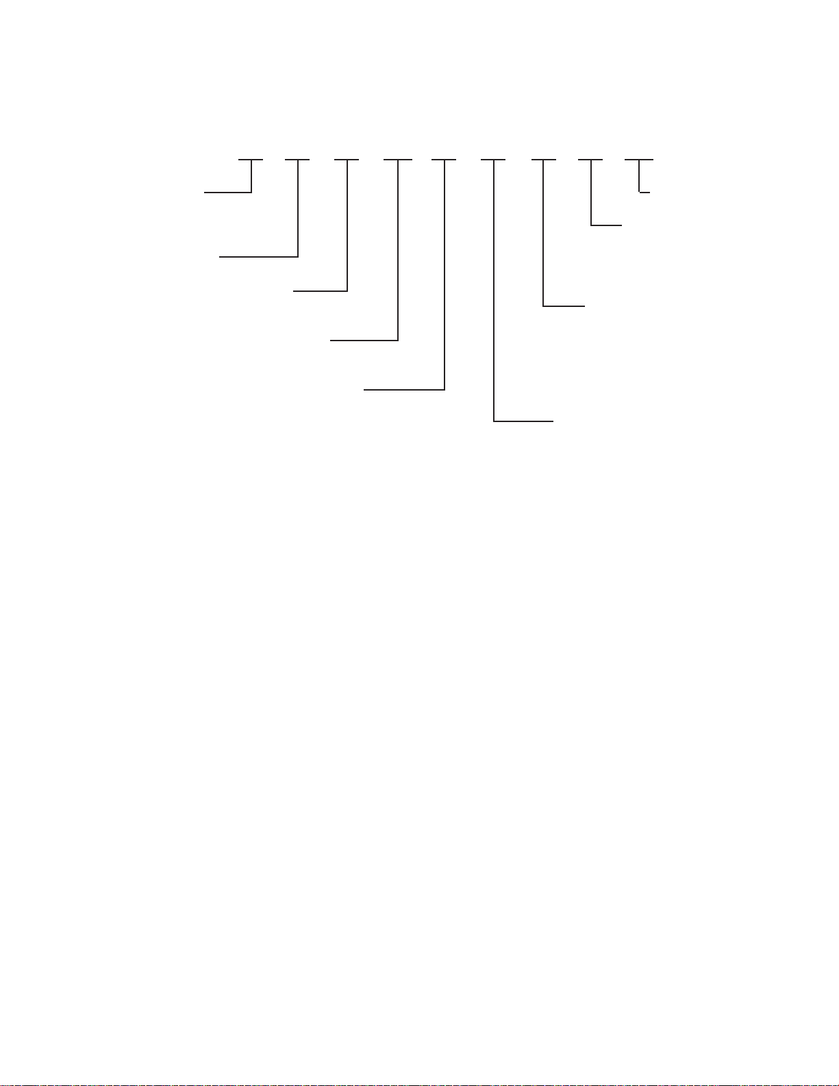
NOMENCLATURE
The Model Number denotes the following characteristics of the unit:
YC A S 0140 E C 17 Y F
FORM 201.18-W1
YORK Chiller
YC = YORK Chiller
Air-Cooled
Compressor Type
S = Screw
Nominal Capacity
Unit Designator
S = Standard Unit
E = High Efficiency
Design Series
Type Start
Y = Star (WYE)-Delta
X = Across-the-Line
Voltage Code
17 = 200-3-60
28 = 230-3-60
40 = 380-3-60
46 = 460-3-60
58 = 575-3-60
Refrigerant
C = R-22
YORK INTERNATIONAL
3
Page 4

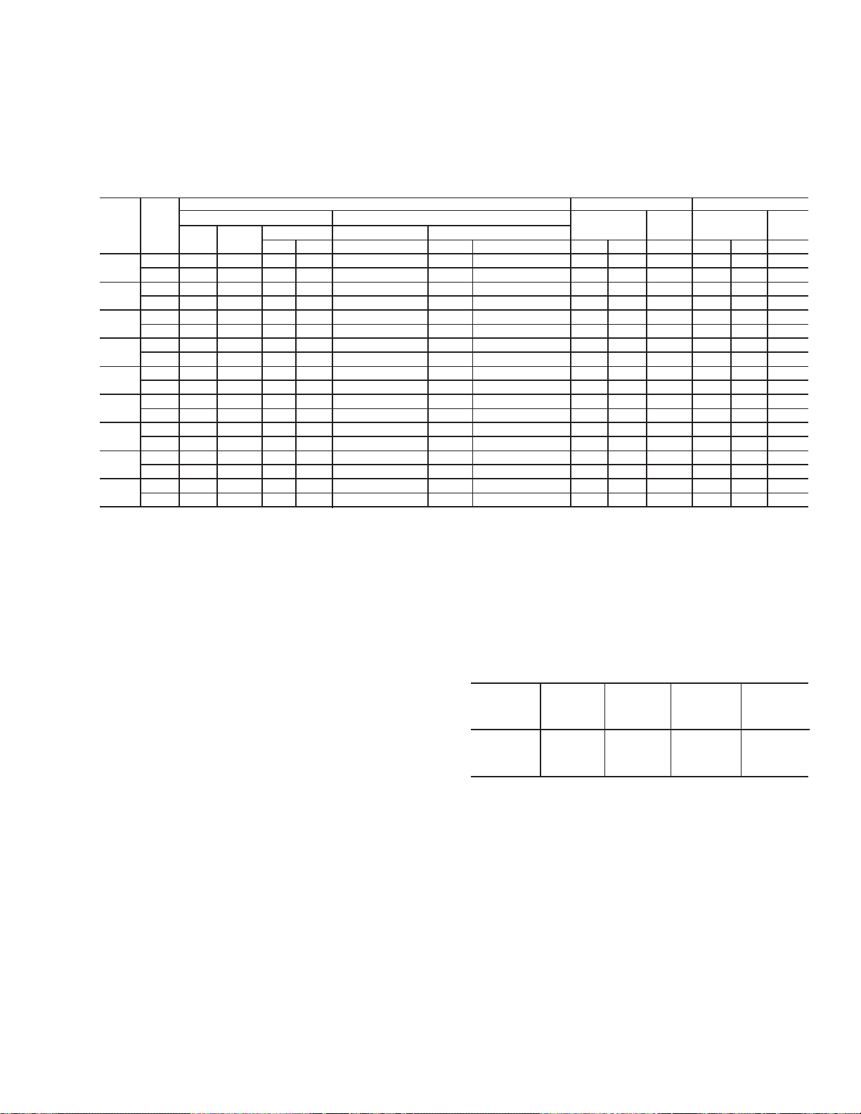
ELECTRICAL DATA
MULTIPLE POINT POWER SUPPLY CONNECTION
Field Connections to Factory provided Terminal Block (Std), Disconnects (Opt), or Breakers(Opt) in each of the two Motor Control Centers.)
MODEL
VOLTS MIN NF
YCAS MCA
200 340 400 450 600 450 600 (2) # 2 - 300 (2) 3/0-250 (3) 2/0-400 246 444 1332 8.2
0130EC 380 181 200 225 350 225 350 # 2 - 300 # 6 AWG - 350 # 6 AWG - 350 130 234 701 4.8
0140EC 380 195 200 250 350 250 350 # 2 - 300 # 6 AWG - 350 # 6 AWG - 350 140 234 701 4.8
0150EC 380 213 250 300 400 300 400 # 1 - 500 # 6 AWG - 350 (2) 3/0-250 155 360 1081 4.8
0160EC 380 213 250 300 400 300 400 # 1 - 500 # 6 AWG - 350 (2) 3/0-250 155 360 1081 4.8
0170EC 380 230 250 300 400 300 400 # 1 - 500 # 6 AWG - 350 (2) 3/0-250 169 360 1081 4.8
0180EC 380 230 250 300 400 300 400 # 1 - 500 # 6 AWG - 350 (2) 3/0-250 169 360 1081 4.8
0200EC 380 250 250 300 450 300 450 # 1 - 500 # 6 AWG - 350 (2) 3/0-250 181 360 1081 4.8
0210EC 380 270 400 350 500 350 500 # 1 - 500 (2) 3/0-250 (2) 3/0-250 197 360 1081 4.8
0230EC 380 270 400 350 500 350 500 # 1 - 500 (2) 3/0-250 (2) 3/0-250 197 360 1081 4.8
230 299 400 400 600 400 600 (2) # 2 - 300 (2) 3/0-250 (2) 3/0-250 214 386 1158 7.8
460 150 150 200 300 200 300 # 2 - 4/0 # 6 AWG - 350 # 6 AWG - 350 107 193 579 4.0
575 119 150 150 225 150 225 # 2 - 4/0 # 6 AWG - 350 # 6 AWG - 350 86 154 463 3.1
200 366 400 450 700 450 700 (2) # 2 - 300 (2) 3/0-250 (3) 2/0-400 267 444 1332 8.2
230 321 400 400 600 400 600 (2) # 2 - 300 (2) 3/0-250 (2) 3/0-250 232 386 1158 7.8
460 161 200 200 300 200 300 # 2 - 300 # 6 AWG - 350 # 6 AWG - 350 116 193 579 4.0
575 128 150 175 225 175 225 # 2 - 4/0 # 6 AWG - 350 # 6 AWG - 350 93 154 463 3.1
200 402 400 500 700 500 700 (2) # 1 - 500 (2) 3/0-250 (3) 2/0-400 295 656 1969 8.2
230 351 400 450 700 450 700 (2) # 2 - 300 (2) 3/0-250 (3) 2/0-400 256 571 1712 7.8
460 176 200 225 350 225 350 # 2 - 300 # 6 AWG - 350 # 6 AWG - 350 128 285 856 4.0
575 141 150 175 250 175 250 # 2 - 4/0 # 6 AWG - 350 # 6 AWG - 350 103 238 715 3.1
200 434 600 600 800 600 800 (2) # 1 - 500 (3) 2/0-400 (3) 2/0-400 321 656 1969 8.2
230 380 400 450 700 450 700 (2) # 1 - 500 (2) 3/0-250 (3) 2/0-400 279 571 1712 7.8
460 191 200 250 350 250 350 # 2 - 300 # 6 AWG - 350 # 6 AWG - 350 140 285 856 4.0
575 152 150 200 300 200 300 # 2 - 4/0 # 6 AWG - 350 # 6 AWG - 350 112 238 715 3.1
200 469 600 600 1000 600 1000 (2) # 1 - 500 (3) 2/0-400 (3) 2/0-400 342 656 1969 8.2
230 412 400 500 800 500 800 (2) # 1 - 500 (2) 3/0-250 (3) 2/0-400 298 571 1712 7.8
460 206 200 250 400 250 400 # 1 - 500 # 6 AWG - 350 # 6 AWG - 350 149 285 856 4.0
575 164 200 200 300 200 300 # 2 - 300 # 6 AWG - 350 # 6 AWG - 350 119 238 715 3.1
200 509 600 700 1000 700 1000 (2) # 1 - 500 (3) 2/0-400 (3) 2/0-400 374 656 1969 8.2
230 445 600 600 800 600 800 (2) # 1 - 500 (3) 2/0-400 (3) 2/0-400 325 571 1712 7.8
460 224 250 300 400 300 400 # 1 - 500 # 6 AWG - 350 (2) 3/0-250 163 285 856 4.0
575 178 200 225 350 225 350 # 2 - 300 # 6 AWG - 350 # 6 AWG - 350 130 238 715 3.1
(Each of Two Field Provided Power Supply Circuits individually protected with Branch Circuit Protection.
1
DISC SW2MIN.3MAX.4MIN.5MAX.
D.E. FUSE C.B. FACTORY PROVIDED (LUGS) WIRE RANGE
SYSTEM #1 FIELD-SUPPLIED WIRING
STD. TERMINAL OPT. NF SVC.
6
BLOCK DISC SW.
7
OPT. C.B. RLA Y-LRA X-LRA FLA (EA)
COMPRESSOR FANS
See page 6 for notes.
4
YORK INTERNATIONAL
Page 5

FORM 201.18-W1
MODEL
VOLTS MIN NF
YCAS MCA
1
DISC SW2MIN.3MAX.4MIN.3MAX.
D.E. FUSE C.B. FACTORY PROVIDED (LUGS) WIRE RANGE
SYSTEM #2 FIELD-SUPPLIED WIRING
STD. TERMINAL OPT. NF SVC.
4
BLOCK DISC SW.
7
COMPRESSOR FANS
OPT. C.B. RLA Y-LRA X-LRA FLA (EA)
200 340 400 450 600 450 600 (2) # 2 - 300 (2) 3/0-250 (3) 2/0-400 246 444 1332 8.2
230 299 400 400 600 400 600 (2) # 2 - 300 (2) 3/0-250 (2) 3/0-250 214 386 1158 7.8
0130EC 380 181 200 225 350 225 350 # 2 - 300 # 6 AWG - 350 # 6 AWG - 350 130 234 701 4.8
460 150 150 200 300 200 300 # 2 - 4/0 # 6 AWG - 350 # 6 AWG - 350 107 193 579 4.0
575 119 150 150 225 150 225 # 2 - 4/0 # 6 AWG - 350 # 6 AWG - 350 86 154 463 3.1
200 366 400 450 700 450 700 (2) # 2 - 300 (2) 3/0-250 (3) 2/0-400 267 444 1332 8.2
230 321 400 400 600 400 600 (2) # 2 - 300 (2) 3/0-250 (2) 3/0-250 232 386 1158 7.8
0140EC 380 195 200 250 350 250 350 # 2 - 300 # 6 AWG - 350 # 6 AWG - 350 140 234 701 4.8
460 161 200 200 300 200 300 # 2 - 300 # 6 AWG - 350 # 6 AWG - 350 116 193 579 4.0
575 128 150 175 225 175 225 # 2 - 4/0 # 6 AWG - 350 # 6 AWG - 350 93 154 463 3.1
200 363 400 450 700 450 700 (2) # 2 - 300 (2) 3/0-250 (3) 2/0-400 265 444 1332 8.2
230 319 400 400 600 400 600 (2) # 2 - 300 (2) 3/0-250 (2) 3/0-250 230 386 1158 7.8
0150EC 380 193 200 250 350 250 350 # 2 - 300 # 6 AWG - 350 # 6 AWG - 350 139 234 701 4.8
460 160 150 200 300 200 300 # 2 - 300 # 6 AWG - 350 # 6 AWG - 350 115 193 579 4.0
575 127 150 175 225 175 225 # 2 - 4/0 # 6 AWG - 350 # 6 AWG - 350 92 154 463 3.1
200 402 400 500 700 500 700 (2) # 1 - 500 (2) 3/0-250 (3) 2/0-400 295 656 1969 8.2
230 351 400 450 700 450 700 (2) # 2 - 300 (2) 3/0-250 (3) 2/0-400 256 571 1712 7.8
0160EC 380 213 200 300 400 300 400 # 1 - 500 # 6 AWG - 350 (2) 3/0-250 155 360 1081 4.8
460 176 200 225 350 225 350 # 2 - 300 # 6 AWG - 350 # 6 AWG - 350 128 285 856 4.0
575 141 150 175 250 175 250 # 2 - 4/0 # 6 AWG - 350 # 6 AWG - 350 103 238 715 3.1
200 402 400 500 700 500 700 (2) # 1 - 500 (2) 3/0-250 (3) 2/0-400 295 656 1969 8.2
230 351 400 450 700 450 700 (2) # 2 - 300 (2) 3/0-250 (3) 2/0-400 256 571 1712 7.8
0170EC 380 213 200 300 400 300 400 # 1 - 500 # 6 AWG - 350 (2) 3/0-250 155 360 1081 4.8
460 176 200 225 350 225 350 # 2 - 300 # 6 AWG - 350 # 6 AWG - 350 128 285 856 4.0
575 141 150 175 250 175 250 # 2 - 4/0 # 6 AWG - 350 # 6 AWG - 350 103 238 715 3.1
200 434 600 600 800 600 800 (2) # 1 - 500 (3) 2/0-400 (3) 2/0-400 321 656 1969 8.2
230 380 400 450 700 450 700 (2) # 1 - 500 (2) 3/0-250 (3) 2/0-400 279 571 1712 7.8
0180EC 380 230 250 300 400 300 400 # 1 - 500 # 6 AWG - 350 (2) 3/0-250 169 360 1081 4.8
460 191 200 250 350 250 350 # 2 - 300 # 6 AWG - 350 # 6 AWG - 350 140 285 856 4.0
575 152 150 200 300 200 300 # 2 - 4/0 # 6 AWG - 350 # 6 AWG - 350 112 238 715 3.1
200 469 600 600 1000 600 1000 (2) # 1 - 500 (3) 2/0-400 (3) 2/0-400 342 656 1969 8.2
230 412 400 500 800 500 800 (2) # 1 - 500 (2) 3/0-250 (3) 2/0-400 298 571 1712 7.8
0200EC 380 250 250 300 450 300 450 # 1 - 500 # 6 AWG - 350 (2) 3/0-250 181 360 1081 4.8
460 206 200 250 400 250 400 # 1 - 500 # 6 AWG - 350 # 6 AWG - 350 149 285 856 4.0
575 164 200 200 300 200 300 # 2 - 300 # 6 AWG - 350 # 6 AWG - 350 119 238 715 3.1
200 469 600 600 1000 600 1000 (2) # 1 - 500 (3) 2/0-400 (3) 2/0-400 342 656 1969 8.2
230 412 400 500 800 500 800 (2) # 1 - 500 (2) 3/0-250 (3) 2/0-400 298 571 1712 7.8
0210EC 380 250 250 300 450 300 450 # 1 - 500 # 6 AWG - 350 (2) 3/0-250 181 360 1081 4.8
460 206 200 250 400 250 400 # 1 - 500 # 6 AWG - 350 # 6 AWG - 350 149 285 856 4.0
575 164 200 200 300 200 300 # 2 - 300 # 6 AWG - 350 # 6 AWG - 350 119 238 715 3.1
200 509 600 700 1000 700 1000 (2) # 1 - 500 (3) 2/0-400 (3) 2/0-400 374 656 1969 8.2
230 445 600 600 800 600 800 (2) # 1 - 500 (3) 2/0-400 (3) 2/0-400 325 571 1712 7.8
0230EC 380 270 400 350 500 350 500 # 1 - 500 (2) 3/0-250 (2) 3/0-250 197 360 1081 4.8
460 224 250 300 400 300 400 # 1 - 500 # 6 AWG - 350 (2) 3/0-250 163 285 856 4.0
575 178 200 225 350 225 350 # 2 - 300 # 6 AWG - 350 # 6 AWG - 350 130 238 715 3.1
YORK INTERNATIONAL
5
Page 6

ELECTRICAL DATA (Continued)
OPTIONAL SINGLE-POINT POWER SUPPLY WITH INTERNAL CIRCUIT BREAKERS
(One Field Provided Power Supply Circuit to the chiller. Field connections to Power Terminal Block or Non-Fused Disconnect in Option Panel.
MODEL
YCAS MIN NF D.E. FUSE C.B. TERMINAL BLOCK NF SERVICE DISC SW
0130EC 380 330 400 400 500 400 500 (2) # 2 - 300 550 (2) 3/0-250 400
0140EC 380 354 400 400 500 400 500 (2) # 2 - 300 550 (2) 3/0-250 400
0150EC 380 371 400 450 600 450 600 (2) # 1 - 500 760 (2) 3/0-250 400
0160EC 380 387 600 450 600 450 600 (2) # 1 - 500 760 (3) 2/0-400 600
0170EC 380 405 600 450 600 450 600 (2) # 1 - 500 760 (3) 2/0-400 600
0180EC 380 419 600 500 600 500 600 (2) # 1 - 500 760 (3) 2/0-400 600
0200EC 380 455 600 600 700 600 700 (2) # 1 - 500 760 (3) 2/0-400 600
0210EC 380 475 600 600 700 600 700 (2) # 1 - 500 760 (3) 2/0-400 600
0230EC 380 491 600 600 700 600 700 (2) # 1 - 500 760 (3) 2/0-400 600
VOLTS
MCA
200 619 800 700 1000 700 1000 (3) # 1 - 500 1140 (3) 2/0-400 800
230 544 600 600 800 600 800 (2) # 1 - 500 760 (3) 2/0-400 600
460 273 400 300 400 300 400 # 1 - 500 380 (2) 3/0-250 400
575 217 250 250 350 250 350 # 1 - 500 380 # 6 AWG - 350 250
200 666 800 800 1000 800 1000 (3) # 1 - 500 1140 (3) 2/0-400 800
230 584 800 700 1000 700 1000 (3) # 1 - 500 1140 (3) 2/0-400 600
460 293 400 350 450 350 450 (2) # 2 - 300 550 (2) 3/0-250 400
575 234 250 300 350 300 350 # 1 - 500 380 # 6 AWG - 350 250
200 699 800 800 1000 800 1000 (3) # 1 - 500 1140 (3) 2/0-400 800
230 612 800 700 1000 700 1000 (3) # 1 - 500 1140 (3) 2/0-400 800
460 307 400 350 450 350 450 (2) # 2 - 300 550 (2) 3/0-250 400
575 246 400 300 350 300 350 # 1 - 500 380 (2) 3/0-250 400
200 729 800 1000 1200 1000 1200 (3) # 1 - 500 1140 (3) 2/0-400 800
230 638 800 800 1000 800 1000 (3) # 1 - 500 1140 (3) 2/0-400 800
460 320 400 400 450 400 450 (2) # 2 - 300 550 (2) 3/0-250 400
575 257 400 300 400 300 400 # 1 - 500 380 (2) 3/0-250 400
200 762 800 1000 1200 1000 1200 (3) # 1 - 500 1140 (3) 2/0-400 800
230 667 800 800 1000 800 1000 (3) # 1 - 500 1140 (3) 2/0-400 800
460 335 400 400 500 400 500 (2) # 2 - 300 550 (2) 3/0-250 400
575 268 400 300 400 300 400 # 1 - 500 380 (2) 3/0-250 400
200 788 1000 1000 1200 1000 1200 (3) # 1 - 500 1140 (4) 4/0-500 1000
230 690 800 800 1000 800 1000 (3) # 1 - 500 1140 (3) 2/0-400 800
460 347 400 400 500 400 500 (2) # 2 - 300 550 (2) 3/0-250 400
575 277 400 350 400 350 400 (2) # 2 - 300 550 (2) 3/0-250 400
200 852 1000 1000 1200 1000 1200 (3) # 1 - 500 1140 (4) 4/0-500 1000
230 749 800 1000 1200 1000 1200 (3) # 1 - 500 1140 (3) 2/0-400 800
460 375 400 450 600 450 600 (2) # 1 - 500 760 (2) 3/0-250 400
575 299 400 350 450 350 450 (2) # 2 - 300 550 (2) 3/0-250 400
200 892 1000 1000 1600 1000 1600 (3) # 1 - 500 1140 (4) 4/0-500 1000
230 782 1000 1000 1200 1000 1200 (3) # 1 - 500 1140 (4) 4/0-500 1000
460 393 600 450 600 450 600 (2) # 1 - 500 760 (3) 2/0-400 600
575 313 400 350 450 350 450 (2) # 2 - 300 550 (2) 3/0-250 400
200 924 1000 1200 1600 1200 1600 (3) # 1 - 500 1140 (4) 4/0-500 1000
230 809 1000 1000 1200 1000 1200 (3) # 1 - 500 1140 (4) 4/0-500 1000
460 407 600 450 600 450 600 (2) # 1 - 500 760 (3) 2/0-400 600
575 324 400 400 500 400 500 (2) # 2 - 300 550 (2) 3/0-250 400
FIELD PROVIDED POWER SUPPLY FACTORY PROVIDED (LUGS) WIRE RANGE
1
DISC SW2MIN.3MAX.4MIN.3MAX.4(LUGS) WIRE RANGE7RATING2(LUGS) WIRE RANGE7RATING
Internal Branch Circuit Protection (Breakers) per Motor Control Center)
FIELD-SUPPLIED WIRING
2
See page 6 for notes.
6
YORK INTERNATIONAL
Page 7

FORM 201.18-W1
MODEL
YCAS
0130EC 380 250 130 234 701 4.8 250 130 234 701 4.8
0140EC 380 250 140 234 701 4.8 250 140 234 701 4.8
0150EC 380 400 155 360 1081 4.8 250 139 234 701 4.8
0160EC 380 400 155 360 1081 4.8 400 155 360 1081 4.8
0170EC 380 400 169 360 1081 4.8 400 155 360 1081 4.8
0180EC 380 400 169 360 1081 4.8 400 169 360 1081 4.8
0200EC 380 400 181 360 1081 4.8 400 181 360 1081 4.8
0210EC 380 400 197 360 1081 4.8 400 181 360 1081 4.8
0230EC 380 400 197 360 1081 4.8 400 197 360 1081 4.8
VOLTS FACTORY
C.B. RLA Y-LRA X-LRA FLA (EA) C.B. RLA Y-LRA X-LRA FLA (EA)
200 600 246 444 1332 8.2 600 246 444 1332 8.2
230 400 214 386 1158 7.8 400 214 386 1158 7.8
460 250 107 193 579 4.0 250 107 193 579 4.0
575 160 86 154 463 3.1 160 86 154 463 3.1
200 600 267 444 1332 8.2 600 267 444 1332 8.2
230 400 232 386 1158 7.8 400 232 386 1158 7.8
460 250 116 193 579 4.0 250 116 193 579 4.0
575 160 93 154 463 3.1 160 93 154 463 3.1
200 600 295 656 1969 8.2 600 265 444 1332 8.2
230 600 256 571 1712 7.8 400 230 386 1158 7.8
460 250 128 285 856 4.0 250 115 193 579 4.0
575 250 103 238 715 3.1 160 92 154 463 3.1
200 600 295 656 1969 8.2 600 295 656 1969 8.2
230 600 256 571 1712 7.8 600 256 571 1712 7.8
460 250 128 285 856 4.0 250 128 285 856 4.0
575 250 103 238 715 3.1 250 103 238 715 3.1
200 600 321 656 1969 8.2 600 295 656 1969 8.2
230 600 279 571 1712 7.8 600 256 571 1712 7.8
460 250 140 285 856 4.0 250 128 285 856 4.0
575 250 112 238 715 3.1 250 103 238 715 3.1
200 600 321 656 1969 8.2 600 321 656 1969 8.2
230 600 279 571 1712 7.8 600 279 571 1712 7.8
460 250 140 285 856 4.0 250 140 285 856 4.0
575 250 112 238 715 3.1 250 112 238 715 3.1
200 600 342 656 1969 8.2 600 342 656 1969 8.2
230 600 298 571 1712 7.8 600 298 571 1712 7.8
460 250 149 285 856 4.0 250 149 285 856 4.0
575 250 119 238 715 3.1 250 119 238 715 3.1
200 600 374 656 1969 8.2 600 342 656 1969 8.2
230 600 325 571 1712 7.8 600 298 571 1712 7.8
460 400 163 285 856 4.0 250 149 285 856 4.0
575 250 130 238 715 3.1 250 119 238 715 3.1
200 600 374 656 1969 8.2 600 374 656 1969 8.2
230 600 325 571 1712 7.8 600 325 571 1712 7.8
460 400 163 285 856 4.0 400 163 285 856 4.0
575 250 130 238 715 3.1 250 130 238 715 3.1
SYSTEM #1 SYSTEM #2
COMPRESSOR DATA FAN DATA
FACTORY
COMPRESSOR DATA FAN DATA
YORK INTERNATIONAL
7
Page 8

ELECTRICAL DATA (Continued)
OPTIONAL SINGLE POINT POWER SUPPLY CONNECTION TO FACTORY CIRCUIT BREAKER
(One Field Provided Power Supply Circuit to the chiller. Field Connection to Circuit Breaker in Option Panel.
No internal Branch Circuit Protection per Motor Control Center.)
MODEL
YCAS
0130EC
0140EC
0150EC
0160EC
0170EC
0180EC
0200EC
0210EC
0230EC
VOLTS
460 273 400 (2) 3/0-250 107 579 4.0 107 579 4.0
575 217 250 # 6 AWG - 350 86 463 3.1 86 463 3.1
460 293 400 (2) 3/0-250 116 579 4.0 116 579 4.0
575 234 400 (2) 3/0-250 93 463 3.1 93 463 3.1
460 307 400 (2) 3/0-250 128 856 4.0 115 579 4.0
575 246 400 (2) 3/0-250 103 715 3.1 92 463 3.1
460 320 400 (2) 3/0-250 128 856 4.0 128 856 4.0
575 257 400 (2) 3/0-250 103 715 3.1 103 715 3.1
460 335 400 (2) 3/0-250 140 856 4.0 128 856 4.0
575 268 400 (2) 3/0-250 112 715 3.1 103 715 3.1
460 347 400 (2) 3/0-250 140 856 4.0 140 856 4.0
575 277 400 (2) 3/0-250 112 715 3.1 112 715 3.1
460 375 630 (3) 2/0-400 149 856 4.0 149 856 4.0
575 299 400 (2) 3/0-250 119 715 3.1 119 715 3.1
460 393 630 (3) 2/0-400 163 856 4.0 149 856 4.0
575 313 400 (2) 3/0-250 130 715 3.1 119 715 3.1
460 407 630 (3) 2/0-400 163 856 4.0 163 856 4.0
575 324 400 (2) 3/0-250 130 715 3.1 130 715 3.1
FIELD SUPPLIED WIRING SYSTEM #1 SYSTEM #2
FACTORY SUPPLIED BREAKER COMPRESSOR FANS COMPRESSOR FANS
1
MCA
RATING2WIRE RANGE7 (LUGS) RLA X-LRA FLA (EA) RLA X-LRA FLA (EA)
NOTE: Wye-Delta Compressor Start not available with this option.
NOTES (pages 2 - 7)
1. Minimum circuit ampacity (MCA) is based on 125% of the rated load amps for the largest motor plus 100% of the rated load amps for all
other loads included in the circuit, per N.E.C. Article 430-24. If a Factory Mounted Control Transformer is provided, add the following to
the system #2 MCA values in the YCAS Tables: -17, add 10 amps; -28, add 9 amps; -40, add 5 amps; -46, add 4 amps; -58, add 3 amps.
2. The recommendation disconnect switch is based on a minimum of 115% of the summation rated load amps of all the loads included in the
circuit, per N.E.C. 440 - 12A1.
3. Minimum fuse size is based on 150% of the largest motor RLA plus 100% of the remaining RLAs (U.L. Standard 1995, Section 36.1).
Minimum fuse rating = (1.5 x largest compressor RLA) + other compressor RLAs + (# fans x each fan motor FLA).
4. Maximum dual element fuse size is based on 225% maximum plus 100% of the rated load amps for all other loads included in the circuit,
per N.E.C. 440-22. Maximum fuse rating = (2.25 x largest compressor RLA) + other compressor RLAs + (# fans x each fan motor FLA).
5. Minimum circuit breaker is 150% maximum plus 100% of rated load amps included in the circuit, per circuit per U.L. 1995 Fig. 36.2.
Minimum circuit breaker rating = (1.5 x largest compressor RLA) + other compressor RLAs + (# fans x each fan motor FLA).
6. Maximum circuit breaker is based on 225% maximum plus 100% of the rated load amps for all loads included in the circuit, per circuit, per
U.L. 1995 Fig. 36.2. Maximum circuit breaker rating = (2.25 x largest compressor RLA) + other compressor RLAs + ( # fans x each fan
motor FLA).
7. The Incoming Wire Range is the minimum and maximum wire size that can be accommodated by unit wiring lugs. The (1), (2), or (3)
indicate the number of termination points or lugs which are available per phase. Actual wire size and number of wires per phase must be
determined based on ampacity and job requirements using N.E.C. wire sizing information. The above recommendations are based on the
National Electric Code and using copper connectors only. Field wiring must also comply with local codes.
8. A ground lug is provided for each compressor system to accommodate field grounding conductor per N.E.C. Article 250-54. A control
circuit grounding lug is also supplied. Incoming ground wire range is #6 - 350 MCM.
9. The field supplied disconnect is a Disconnecting Means as defined in N.E.C. 100.B, and is intended for isolating the unit from the
available power supply to perform maintenance and troubleshooting. This disconnect is not intended to be a Load Break Device.
10. Units equipped with Star-Delta compressor motor start must also include Factory provided circuit breakers in each motor control center.
11. The wiring recommendations are based on the National Electrical Code using copper connectors only. Field wiring must also comply with
local codes.
8
YORK INTERNATIONAL
Page 9
FORM 201.18-W1
OPTIONAL SINGLE POINT POWER SUPPLY CONNECTION WITH FIELD SUPPLIED CIRCUIT PROTECTION
(One Field Provided Power Supply Circuit to the chiller. Field Connection to Power Terminal Block or Disconnect Switch in the Option Panel.
No internal Branch Circuit Protection per Motor Control Center.)
MODEL
YCAS
0130EC
0140EC
0150EC
0160EC
0170EC
0180EC
0200EC
0210EC
0230EC
FIELD PROVIDED POWER SUPPLY FACTORY PROVIDED (LUGS) WIRE RANGE COMPRESSOR FANS COMPRESSOR FANS
VOLTS
460 273 400 300 400 # 1 - 500 400 (2) 3/0-250 107 579 4.0 107 579 4.0
575 217 250 250 350 # 1 - 500 250 # 6 AWG - 350 86 463.2 3.1 86 463 3.1
460 293 400 350 450 (2) # 2 - 300 400 (2) 3/0-250 116 579 4.0 116 579 4.0
575 234 250 300 350 # 1 - 500 250 # 6 AWG - 350 93 463.2 3.1 93 463 3.1
460 307 400 350 450 (2) # 2 - 300 400 (2) 3/0-250 128 856 4.0 115 579 4.0
575 246 400 300 350 # 1 - 500 250 # 6 AWG - 350 103 715 3.1 92 463 3.1
460 320 400 400 450 (2) # 2 - 300 400 (2) 3/0-250 128 856 4.0 128 856 4.0
575 257 400 300 400 # 1 - 500 400 (2) 3/0-250 103 715 3.1 103 715 3.1
460 335 400 400 500 (2) # 2 - 300 400 (2) 3/0-250 140 856 4.0 128 856 4.0
575 268 400 300 400 # 1 - 500 400 (2) 3/0-250 112 715 3.1 103 715 3.1
460 347 400 400 500 (2) # 2 - 300 400 (2) 3/0-250 140 856 4.0 140 856 4.0
575 277 400 350 400 (2) # 2 - 300 400 (2) 3/0-250 112 715 3.1 112 715 3.1
460 375 400 450 600 (2) # 1 - 500 400 (2) 3/0-250 149 856 4.0 149 856 4.0
575 299 400 350 450 (2) # 2 - 300 400 (2) 3/0-250 119 715 3.1 119 715 3.1
460 393 600 450 600 (2) # 1 - 500 400 (2) 3/0-250 163 856 4.0 149 856 4.0
575 313 400 350 450 (2) # 2 - 300 400 (2) 3/0-250 130 715 3.1 119 715 3.1
460 407 600 450 600 (2) # 1 - 500 630 (3) 2/0-400 163 856 4.0 163 856 4.0
575 324 400 400 500 (2) # 2 - 300 400 (2) 3/0-250 130 715 3.1 130 715 3.1
MIN NF D.E. FUSE TERMINAL BLOCK NF SERV DISC SW DATA DATA DATA DATA
1
MCA
DISC SW2MIN3MAX4(LUGS) WIRE RANGE7RATING2(LUGS) WIRE RANGE7RLA X-LRA FLA (EA) RLA X-LRA FLA (EA)
FIELD SUPPLIED WIRING SYSTEM #1 SYSTEM #2
LEGEND
ACR-LINE ACROSS THE LINE START
C.B. CIRCUIT BREAKER
D.E. DUAL ELEMENT FUSE
DISC SW DISCONNECT SWITCH
FACT MOUNT CB FACTORY-MOUNTED CIRCUIT BREAKER
FLA FULL LOAD AMPS
HZ HERTZ
MAX MAXIMUM
UNIT
VOLTAGE
Standard
Models w/o 115-1-60 20A 20A 30A
Transformers
CONTROL POWER SUPPLY
CONTROL MIN MAX DUAL NON-FUSED
POWER CIRCUIT ELEMENT DISC. SW.
SUPPLY AMPACITY FUSE SIZE SIZE
MCA MINIMUM CIRCUIT AMPACITY
MIN MINIMUM
MIN NF MINIMUM NON-FUSED
RLA RUNNING LOAD AMPS
S.P. WIRE SINGLE-POINT WIRING
UNIT MTD SERV SW UNIT-MOUNTED SERVICE (NON-FUSED DISCONNECT SWITCH)
WYE-DELTA WYE-DELTA START
X-LRA ACROSS-THE-LINE INRUSH LOCKED ROTOR AMPS
Y-LRA WYE-DELTA INRUSH LOCKED ROTOR AMPS
VOLTAGE CODE
-17 = 200-3-60
-28 = 230-3-60
-40 = 380-3-60
-46 = 460-3-60
-58 = 575-3-60
YORK INTERNATIONAL
9
Page 10

ACROSS-THE-LINE START
NOTES:
1. Field wiring to be in accordance with the current
edition of the National Electrical Code as well as all
other applicable codes and specifications.
2. Numbers along the right side of a diagram are line
identification numbers. The numbers at each line
indicate the line number location of relay contacts.
An unlined contact location signifies a normally closed
contact. Numbers adjacent to circuit lines are the
circuit identification numbers.
3. Any customer supplied contacts must be suitable
for switching 24VDC. (Gold contacts recommended.) Control Wiring must not be run in the same
conduit with any line voltage wiring.
4. To cycle unit on and off automatically with contact
shown, install a cycling device in series with the
flow switch (FSLW). See Note 3 for contact rating
and wiring specifications. Also refer to cautions on
the following page.
5. To stop unit (Emergency Stop) with contacts other
than those shown, install the stop contact between
5 and 1. If a stop device is not installed, a jumper
must be connected between terminals 5 and 1. Device must have a minimum contact rating of 100VA
at 115 volts A.C.
6. Alarm contacts are for annunciating alarm/unit malfunction. Contacts are rated at 115V, 100VA, resistive load only, and must be suppressed at load by
user.
7. See Installation, Operation and Maintenance Manual
when optional equipment is used.
8. Control panel to be securely connected to earth
ground.
9. Us 2KVA transformer in optional transformer kit unless there are optional oil separator sump heaters
which necessitates using a 3KVA transformer.
WIRING DIAGRAM
LD03226
LEGEND
T S
Transient Voltage Suppression
Terminal Block for Customer Connections
Terminal Block for Customer Low Voltage
(Class 2) Connections. See Note 2
Terminal Block for YORK Connections Only
Wiring and Components by YORK
Optional Equipment
Wiring and/or Components by Others
FIG. 1 – ELEMENTARY DIAGRAM – ACROSS-THE-LINE START
10
LD03227
YORK INTERNATIONAL
Page 11

WIRING DIAGRAM
ACROSS-THE-LINE START
FORM 201.18-W1
YORK INTERNATIONAL
LD03228
11
Page 12

ELEMENTARY DIAGRAM
FIG. 1 – CONTINUED
12
YORK INTERNATIONAL
Page 13

ELEMENTARY DIAGRAM
FORM 201.18-W1
LD03279
CAUTION:
No Controls (relays, etc.) should
be mounted in the Smart Panel
enclosure or connected to power
supplies in the control panel.
Additionally, control wiring not
connected to the Smart Panel
should not be run through the
cabinet. This could result in nuisance faults.
CAUTION:
Any inductive devices (relays)
wired in series with the flow
switch for start/stop, into the
Alarm circuitry, or pilot relays
for pump starters wired through
motor contactor auxiliary contacts must be suppressed with
YORK P/N 031-00808-000 suppressor across the relay/
contactor coil.
Any contacts connected to flow
switch inputs or BAS inputs on
terminals 13 - 19 or TB3, or any
other terminals, must be suppressed with a YORK P/N 03100808-000 suppressor across
the relay/contactor coil.
YORK INTERNATIONAL
CAUTION:
Control wiring connected to the
control panel should never be
run in the same conduit with
power wiring.
CONTROL POWER SUPPLY
UNIT
VOLTAGE
ALL MODELS
W/O TRANS.
MODELS -1 7 200-1-60 15A 15A 250V 30A 240V
WITH -2 8 230-1-60 15A 15A 250V 30A 240V
TRANS. - 46 400-1-60 8A 8A 600V 30A 480V
* -58 575-1-60 8A 8A 600V 30A 600V
* All primary and secondary wiring between transformer and control panel included.
CONTROL MIN MAX DUAL NON-FUSED
POWER CIRCUIT ELEMENT DISC.
SUPPLY AMP. FUSE SIZE SWITCH SIZE
115-1-50/60 20A 20A 250V 30A 240V
13
Page 14

NOTES:
1. Field wiring to be in accordance with the current
edition of the National Electrical Code as well as all
other applicable codes and specifications.
2. Numbers along the right side of a diagram are line
identification numbers. The numbers at each line
indicate the line number location of relay contacts.
An unlined contact location signifies a normally closed
contact. Numbers adjacent to circuit lines are the
circuit identification numbers.
3. Any customer supplied contacts must be suitable
for switching 24VDC. (Gold contacts recommended.) Control Wiring must not be run in the same
conduit with any line voltage wiring.
4. To cycle unit on and off automatically with contact
shown, install a cycling device in series with the
flow switch (FSLW). See Note 3 for contact rating
and wiring specifications. Also refer to cautions on
the following page.
5. To stop unit (Emergency Stop) with contacts other
than those shown, install the stop contact between
5 and 1. If a stop device is not installed, a jumper
must be connected between terminals 5 and 1. Device must have a minimum contact rating of 100VA
at 115 volts A.C.
6. Alarm contacts are for annunciating alarm/unit malfunction. Contacts are rated at 115V, 100VA, resistive load only, and must be suppressed at load by
user.
7. See Installation, Operation and Maintenance Manual
when optional equipment is used.
8. Control panel to be securely connected to earth
ground.
9. Us 2KVA transformer in optional transformer kit unless there are optional oil separator sump heaters
which necessitates using a 3KVA transformer.
WIRING DIAGRAM
WYE-DELTA START
LD03226
LEGEND
T S
Transient Voltage Suppression
Terminal Block for Customer Connections
Terminal Block for Customer Low Voltage
(Class 2) Connections. See Note 2
Terminal Block for YORK Connections Only
Wiring and Components by YORK
Optional Equipment
Wiring and/or Components by Others
FIG. 1 – ELEMENTAR Y DIAGRAM – WYE-DEL TA ST AR T
14
LD03227
YORK INTERNATIONAL
Page 15

WIRING DIAGRAM
WYE-DELTA START
FORM 201.18-W1
YORK INTERNATIONAL
LD03229
15
Page 16

ELEMENTARY DIAGRAM
FIG. 1 – CONTINUED
16
YORK INTERNATIONAL
Page 17

ELEMENTARY DIAGRAM
FORM 201.18-W1
LD03279
CAUTION:
No Controls (relays, etc.) should
be mounted in the Smart Panel
enclosure or connected to power
supplies in the control panel.
Additionally, control wiring not
connected to the Smart Panel
should not be run through the
cabinet. This could result in nuisance faults.
CAUTION:
Any inductive devices (relays)
wired in series with the flow
switch for start/stop, into the
Alarm circuitry, or pilot relays
for pump starters wired through
motor contactor auxiliary contacts must be suppressed with
YORK P/N 031-00808-000 suppressor across the relay/
contactor coil.
Any contacts connected to flow
switch inputs or BAS inputs on
terminals 13 - 19 or TB3, or any
other terminals, must be suppressed with a YORK P/N 03100808-000 suppressor across
the relay/contactor coil.
YORK INTERNATIONAL
CAUTION:
Control wiring connected to the
control panel should never be
run in the same conduit with
power wiring.
CONTROL POWER SUPPLY
UNIT
VOLTAGE
ALL MODELS
W/O TRANS.
MODELS -1 7 200-1-60 15A 15A 250V 30A 240V
WITH -2 8 230-1-60 15A 15A 250V 30A 240V
TRANS. - 46 400-1-60 8A 8A 600V 30A 480V
* -58 575-1-60 8A 8A 600V 30A 600V
* All primary and secondary wiring between transformer and control panel included.
CONTROL MIN MAX DUAL NON-FUSED
POWER CIRCUIT ELEMENT DISC.
SUPPLY AMP. FUSE SIZE SWITCH SIZE
115-1-50/60 20A 20A 250V 30A 240V
17
Page 18

18
YORK INTERNATIONAL
Page 19

FORM 201.18-W1
YORK INTERNATIONAL
LD03280
19
Page 20

LEGEND
20
LD03281
YORK INTERNATIONAL
Page 21

LD03282
FORM 201.18-W1
LD03283
YORK INTERNATIONAL
LD03284
21
Page 22

CONNECTION DIAGRAM (SYSTEM WIRING)
LD03230
22
LD03231
LD03232
YORK INTERNATIONAL
Page 23

COMPRESSOR TERMINAL BOX
FORM 201.18-W1
YORK INTERNATIONAL
LD03233
23
Page 24

MULTI-POINT POWER SUPPLY WIRING STANDARD UNIT
LD03254
SINGLE POINT POWER SUPPLY WIRING WITH CIRCUIT BREAKERS
24
LD03255
YORK INTERNATIONAL
Page 25

FORM 201.18-W1
SINGLE POINT POWER WIRING WITH FIELD SUPPLIED CIRCUIT PROTECTION
LD03256
SINGLE POINT POWER WIRING WITH CIRCUIT BREAKERS
YORK INTERNATIONAL
LD03257
25
Page 26

ELECTRICAL POWER WIRING OPTIONS: TERMINAL BLOCKS
LD03258
ELECTRICAL POWER WIRING OPTIONS: NON FUSED DISCONNECT SWITCH
26
LD03259
ELECTRICAL POWER WIRING OPTIONS: TERMINAL BLOCKS
LD03260
YORK INTERNATIONAL
Page 27

FORM 201.18-W1
LD03286
YORK INTERNATIONAL
27
Page 28

LD03286
P.O.Box 1592, York,Pennsylvania USA 17405-1592 Subject to change without notice. Printed in USA
Copyright © by York International Corporation 1998 ALL RIGHTS RESERVED
Form 201.18-W1 (1298)
Supersedes: 201.18-W1 (798)
 Loading...