

Page 1

TECHNICAL
TECHNICAL
GUIDE
GUIDE
SPLIT-SYSTEM HEAT PUMPS
13 SEER – R-22
MODELS:
E*BD-F018 THRU 060
(1.5 THRU 5 NOMINAL TONS, 1 PHASE)
E*BD-(T,W)036 THRU 060
(2.5 THRU 5 NOMINAL TONS, 3 PHASE)
ISO 9001
Certified Quality
Management System
LISTED
Due to continuous product improvement, specifications
are subject to change without notice.
Visit us on the web at www.york.com
Additional rating information can be found at
www.ahridirectory.org
246819-BTG-H-0208
DESCRIPTION
The 13 SEER series heat pumps are designed for use with a
variety of UPG evaporator sections to suit any application
need. A full line of matching Add-On Coils are available for
use with upflow, downflow or horizontal furnaces. Matching
Air Handlers are also available for upflow, downflow or horizontal installation to provide a complete system. Electric heat
may be installed in air handlers. All units are factory charged
to assure easy installation.
WARRANTY
Single Phase Units:
5-year limited parts warranty.
5-year limited compressor warranty.
Three Phase Units:
1-year limited parts warranty.
5-year limited compressor warranty.
FEATURES
• DURABLE CONSTRUCTION - The outdoor unit is constructed of pre-painted steel that offers tough protection
against corrosion and resists fading when exposed to sunlight. Drain holes are incorporated into the base pan to permit free drainage of moisture.
• QUALITY COILS - The coil is constructed of enhanced
copper tube and aluminum fins.
• COIL PROTECTION - Coils are protected from damage by
a polymer mesh applied between the coil face, and a PVC
coated steel coil guard.
• PROTECTED COMPRESSOR - The hermetic compressor
is internally protected against high pressure and temperature by the simultaneous operation of a high pressure relief
valve and temperature sensors which stop the compressor
if operating temperatures go too high. Both protectors
reset automatically. A discharge line solid core filter drier
further protects the compressor.
• Complete System Control – These heat pumps utilize
the unique microprocessor defrost control system to provide optimal comfort and to monitor the overall system for
reliable operation. The defrost control system continuously
monitors the space environment to maintain optimum efficiency. It initiates defrost only when necessary to further
reduce heating costs and improve reliability. In the event
improper operating conditions occur, the control will automatically shut the system down to extend the life of the
heat pump. Rapid cycling is prevented by use of an internal anti-recycle timer.
• LOW OPERATING SOUND LEVEL - The compressor is
mounted on rubber isolators to reduce operating sounds.
The slow moving condenser fan keeps air turbulence and
sound to a low level.
• EASY ACCESS - Removable panel affords accessibility to
the electrical box.
• FULLY CHARGED AND FACTORY WIRED - to simply
installation and reduce labor costs. Only power supply and
control wiring and refrigerant lines must be connected. All
models are sweat connect with reusable service valves.
• Factory tested - to verify system operation and control
functioning before shipment.
• U.L. and C.U.L. listed - approved for outdoor application.
Certified in accordance with the Unitary Small Equipment certification program, which is based on ARI Standard 210/240.
FOR DISTRIBUTION USE ONLY - NOT TO BE USED AT POINT OF RETAIL SALE
Page 2
246819-BTG-H-0208
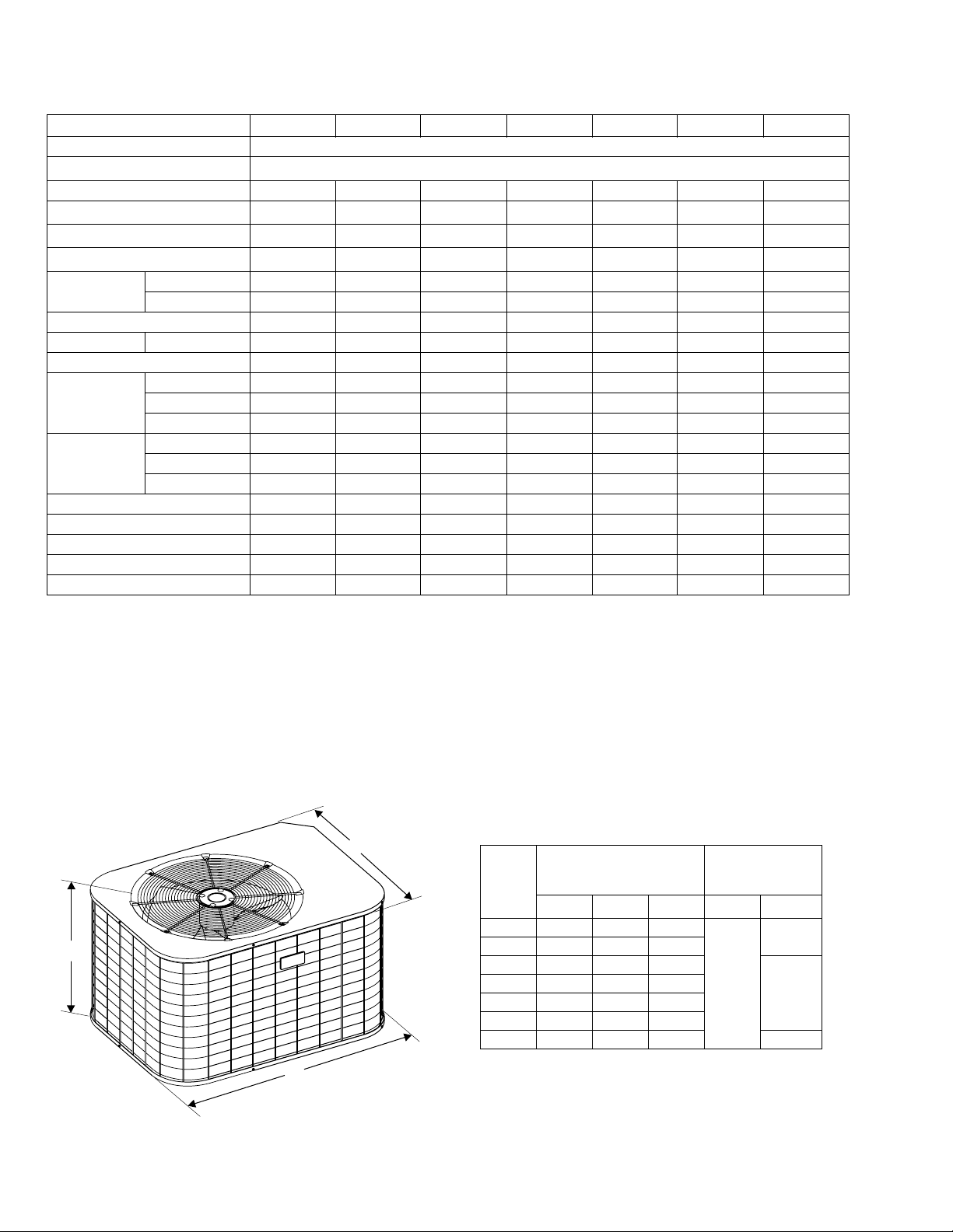
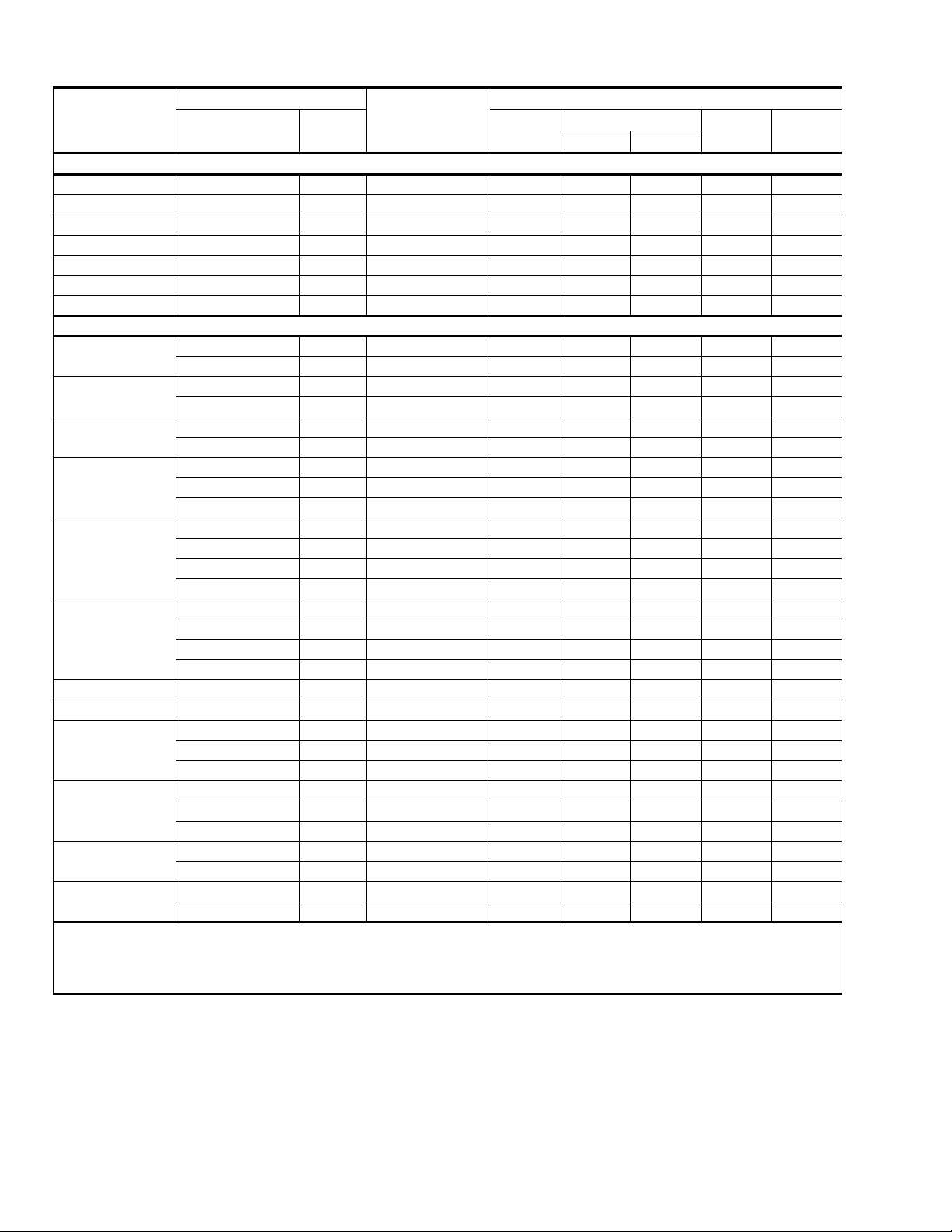
Physical and Electrical Data - 1 Phase
MODEL
Unit Supply Voltage 208-230V, 1φ, 60Hz
Normal Voltage Range
Minimum Circuit Ampacity 9.9 15.0 16.9 19.8 25.0 32.7 37.8
Max. Overcurrent Device Amps
Min. Overcurrent Device Amps
Compressor Type
Compressor
Amps
Crankcase Heater Yes Yes Yes Yes Yes No No
Fan Motor Amps Rated Load 0.5 1.5 1.5 1.5 1.5 1.5 1.5
Fan Diameter Inches 22 22 22 22 22 24 24
Fan Motor
Coil
Liquid Line Set OD (Field Installed) 3/8 3/8 3/8 3/8 3/8 3/8 3/8
Vapor Line Set OD (Field Installed) 3/4 3/4 7/8 7/8 7/8 7/8 1-1/8
Unit Charge (Lbs. - Oz.)
Charge Per Foot, Oz. 0.68 0.68 0.70 0.70 0.70 0.70 0.76
Operating Weight Lbs. 172 184 196 208 208 250 294
1. Rated in accordance with ARI Standard 110, utilization range “A”.
2. Dual element fuses or HACR circuit breaker. Maximum allowable overcurrent protection.
3. Dual element fuses or HACR circuit breaker. Minimum recommended overcurrent protection.
4. All scrolls listed with a superscript “D” are Danfoss scrolls. All scrolls listed with a superscript “C” are Copeland scrolls.
5. The Unit Charge is correct for the outdoor unit, matched indoor coil and 15 feet of refrigerant tubing. For tubing lengths other than 15
feet, add or subtract the amount of refrigerant, using the difference in length multiplied by the per foot value.
1
4
Rated Load 7.5 10.7 12.4 14.6 18.8 25.0 29.1
Locked Rotor 41 44 60 78 78 115 150
Rated HP 1/15 1/4 1/4 1/4 1/4 1/4 1/4
Nominal RPM 850 850 850 850 850 850 850
Nominal CFM 2,000 3,250 3,450 3,500 3,500 3,400 3,500
Face Area Sq. Ft. 15.72 18.34 20.96 23.58 23.58 24.00 27.00
Rows Deep1111122
Fin / Inches 22 22 22 22 22 18 18
5
EABD-F018S EABD-F024S EABD-F030S EABD-F036S EABD-F042S EABD-F048S EABD-F060S
187 to 252
2
3
15 25 25 30 40 50 60
15 20 20 20 30 35 40
Recip Recip Recip Recip Recip
Scroll
D
7 - 1 6 - 6 8 - 7 8 - 7 8 - 7 12 - 8 16 - 7
Scroll
D
All dimensions are in inches. They are subject to change
without notice. Certified dimensions will be provided upon
request.
C
Unit
Model
Dimensions
1
A
(Inches)
B C Liquid Vapor
018 27 37 27
A
024 31 37 27
030 35 37 27
036 39 37 27
042 39 37 27
048 34 43 32
060 38 43 32 7/8”*
B
1. Including Fan Guard.
* Adapter fitting required for 1-1/8” line set.
Refrigerant
Connection
Service Valve Size
3/4”
3/8”
7/8”
2 Unitary Products Group
Page 3
246819-BTG-H-0208
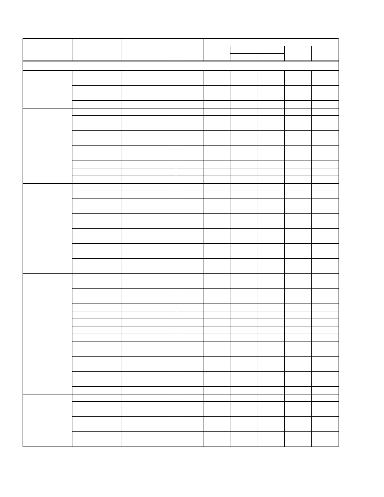
Additional R-22 Charge / Orifice Size for Various Matched Systems - 1 Phase
Outdoor Unit EABD-F018S EABD-F024S EABD-F030S EABD-F036S EABD-F042S EABD-F048S EABD-F060S
Required TXV 1TVM2A1 1TVM2A1 1TVM2A1 1TVM2A1 1TVM2C1 1TVM2C1 1TVM2C1
Factory Charge, lbs-oz 7 - 1 6 - 9 8 - 9 8 - 7 8 - 7 12 - 8 16 - 7
Indoor Coil
FC/MC/PC/UC18A2A 0––––––
FC/MC/PC/UC18B2A 0––––––
FC/MC/PC/UC24A2A –0–––––
FC/MC/PC/UC24B2A –0–––––
FC/MC/PC/UC30A2A –0–––––
FC/MC/PC/UC30B2A –0–––––
FC/MC/PC35B2A ––09–––
FC/MC/PC35C2C ––09–––
FC/MC/PC/UC42B2C ––09–––
FC/MC/PC/UC42C2C ––09–––
FC/MC/PC/UC48C2C – – – 9 14 – –
FC/MC/PC/UC48D2C – – – 9 14 – –
FC/PC/UC60C2C –––––77
FC/MC/PC/UC60D2C –––––77
MC61D2C –––––77
HC18A2A 0––––––
HC30A2A –0–––––
HC36B2A ––0––––
HC42C2C –––9–––
HC60C2C –––––77
HD24A2A –0–––––
HD36B2A ––09–––
HD48C2C – – – – 14 – –
HD60D2C –––––77
AHP18B2A 0––––––
AHP24B2A –0–––––
AHP30B2A ––0––––
AHP36C2A –––9–––
AHP42C2C –––9–––
AHP/SHP48D2C – – – – 14 7 –
AHP/SHP60D2C –––––77
AV24B2A 00–––––
AV36C2A ––09–––
AV/SV48D2C – – – – 14 7 –
AV/SV60D2C ––––––7
FC/MC/PC/UC18A3X 0––––––
FC/MC/PC/UC18B3X 0––––––
FC/MC/PC/UC24A3X –0–––––
FC/MC/PC/UC24B3X –0–––––
FC/MC/PC/UC30A3X –0–––––
FC/MC/PC/UC30B3X –0–––––
FC/MC/PC35B3X ––09–––
FC/MC/PC35X3X ––09–––
FC/MC/PC/UC42B3X ––09–––
FC/MC/PC/UC42X3X ––09–––
FC/MC/PC/UC48C3X – – – 9 14 – –
FC/MC/PC/UC48D3X – – – 9 14 – –
FC/PC/UC60C3X –––––77
FC/MC/PC/UC60D3X –––––77
MC61D3X –––––77
HC18A3X 0––––––
HC30A3X –0–––––
HC36B3X ––0––––
HC42C3X –––9–––
HC60C3X –––––77
For Notes See Page 4.
1,2
Additional Charge, Oz
Unitary Products Group 3
Page 4
246819-BTG-H-0208
Additional R-22 Charge / Orifice Size for Various Matched Systems - 1 Phase (Continued)
Outdoor Unit EABD-F018S EABD-F024S EABD-F030S EABD-F036S EABD-F042S EABD-F048S EABD-F060S
Required TXV 1TVM2A1 1TVM2A1 1TVM2A1 1TVM2A1 1TVM2C1 1TVM2C1 1TVM2C1
Factory Charge, lbs-oz 7 - 1 6 - 9 8 - 9 8 - 7 8 - 7 12 - 8 16 - 7
Indoor Coil
HD24A3X –0–––––
HD36B3X ––09–––
HD48C3X – – – – 14 – –
HD60D3X –––––77
AHP18B3X 0––––––
AHP24B3X –0–––––
AHP30B3X ––0––––
AHP36C3X –––9–––
AHP42C3X –––9–––
AHP/SHP48D3X – – – – 14 7 –
AHP/SHP60D3X –––––77
AV24B3X 00–––––
AV36C3X ––09–––
AV/SV48D3X – – – – 14 7 –
AV/SV60D3X – – – – 14 7 7
F*FP024H06T2A 0 – –––––
F*FP030H06T2A – 0 –––––
F*FP040H06T2A – – 09–––
F*FP042H06T2A – – –9–––
F*FV060H06T2C – – –––77
FOOTNOTES:
* This loose coil match does not achieve 13 SEER.
PROCEDURES:
1. Unit factory charge listed on the unit nameplate includes refrigerant for the condenser, the smallest evaporator and 15 feet of inter-
2. Verify the orifice size and the additional charge required for the specific evaporator coil in the system using the above table.
3. Additional charge for the amount of interconnecting line tubing greater than 15 feet at the rate specified in the table above.
4. Permanently mark the unit nameplate with the total system charge. Total System Charge = Base charge (as shipped) + adder for
5. If the orifice in the evaporator was changed, verify the evaporator nameplate has been marked with the correct orifice/TXV size.
1,2
1. Systems matched with furnace or air handlers not equipped with blower-off delays may require blower Time Delay Kit 2FD06700224.
2. PC coils cannot be used in downflow or horizontal applications. FC coils cannot be used in horizontal applications.
connecting line tubing.
evaporator + adder for line set.
Additional Charge, Oz
4 Unitary Products Group
Page 5
246819-BTG-H-0208
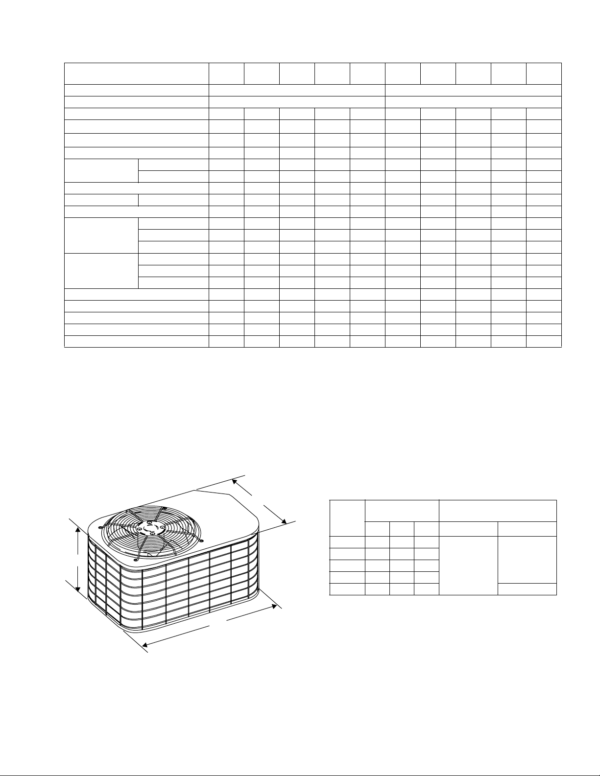
Physical and Electrical Data - 3 Phase
MODEL
Unit Supply Voltage 208-230V, 3φ, 60Hz 460V, 3φ, 60Hz
Normal Voltage Range
Minimum Circuit Ampacity 12.1 14.3 14.4 20.2 23.1 5.6 6.9 7.2 9.5 11.2
Max. Overcurrent Device Amps
Min. Overcurrent Device Amps
Compressor Type Recip Recip Recip Scroll Scroll Recip Recip Recip Scroll Scroll
Compressor Amps
Crankcase Heater Yes Yes Yes No No Yes Yes Yes No No
Fan Motor Amps Rated Load 1.5 1.5 1.5 1.5 1.5 0.7 0.7 0.7 0.7 0.7
Fan Diameter Inches 22 22 22 24 24 22 22 22 24 24
Fan Motor
Coil
Liquid Line Set OD (Field Installed) 3/8 3/8 3/8 3/8 3/8 3/8 3/8 3/8 3/8 3/8
Vapor Line Set OD (Field Installed) 7/8 7/8 7/8 7/8 1-1/8 7/8 7/8 7/8 7/8 1-1/8
Unit Charge (Lbs. - Oz.)
Charge Per Foot, Oz. 0.70 0.70 0.70 0.70 0.76 0.70 0.70 0.70 0.70 0.78
Operating Weight Lbs. 196 208 208 250 294 196 208 208 250 294
1. Rated in accordance with ARI Standard 110, utilization range “A”.
2. Dual element fuses or HACR circuit breaker. Maximum allowable overcurrent protection.
3. Dual element fuses or HACR circuit breaker. Minimum recommended overcurrent protection.
4. The Unit Charge is correct for the outdoor unit, matched indoor coil and 15 feet of refrigerant tubing. For tubing lengths other than
15 feet, add or subtract the amount of refrigerant, using the difference in length multiplied by the per foot value. If line exceeds 25
feet, you may refer to publications software 036-68001-001 for proper line sizing.
1
2
3
Rated Load 8.5 10.2 10.4 15.0 16 3.9 4.9 6.1 6.1 8
Locked Rotor 62 72 71 95 123 30 45 45 45 70
Rated HP 1/4 1/4 1/4 1/4 1/4 1/4 1/4 1/4 1/4 1/4
Nominal RPM 850 850 850 850 850 850 850 850 850 850
Nominal CFM 3450 3500 3500 3400 3500 3450 3500 3500 3400 3500
Face Area Sq. Ft. 20.96 23.58 23.58 24.00 27.00 20.96 23.58 23.58 24.00 27.00
Rows Deep 1112211122
Fin / Inches 22 22 22 18 18 22 22 22 18 18
4
EABDT030S
8 - 7 8 - 7 8 - 7 12 - 8 16 - 7 8 - 7 8 - 7 8 - 7 12 - 8 16 - 7
EABDT036S
20 20 20 35 40 15 15 15 15 15
15 15 15 25 25 15 15 15 15 15
EABDT042S
187 to 252 432 to 532
EABDT048S
EABDT060S
EABD-
W030S
EABD-
W036S
EABDW042S
EABD-
W048S
EABD-
W060S
All dimensions are in inches. They are subject to change without notice. Certified dimensions will be provided upon request.
DIMENSIONS
C
Unit
Model
030 35 37 27
A
036 39 37 27
042 39 37 27
048 34 43 32
060 38 43 32 7/8”*
1. Including Fan Guard.
* Adapter fitting required for 1-1/8” line set.
B
Unitary Products Group 5
Dimensions
(Inches)
1
B C Liquid Vapor
A
Refrigerant Connection
Service Valve Size
3/8”
7/8”
Page 6

246819-BTG-H-0208
Additional R-22 Charge / Orifice Size for Various Matched Systems - 3 Phase
Outdoor Unit EABD-(T,W)030S EABD-(T,W)036S EABD-(T,W)042S EABD-(T,W)048S EABD-(T,W)060S
Required TXV 1TVM2A1 1TVM2A1 1TVM2C1 1TVM2C1 1TVM2C1
Factory Charge, lbs-oz 8 - 9 8 - 7 8 - 7 12 - 8 16 - 9
Indoor Coil
FC/MC/PC/UC35B2C09–––
FC/MC/PC/UC35C2C09–––
FC/MC/PC/UC42B2C09–––
FC/MC/PC/UC42C2C09–––
FC/MC/PC/UC48C2C – 9 14 – –
FC/MC/PC/UC48D2C – 9 14 – –
FC/PC/UC60C2C –––75
FC/MC/PC/UC60D2C–––75
MC61D2C –––75
HC36B2A 0––––
HC42C2C –9–––
HC60C2C –––75
HD36B2A 09–––
HD48C2C – – 14 – –
HD60D2C –––75
AHP30B2A 0––––
AHP36C2A –9–––
AHP42C2C –9–––
AHP/SHP48D2C – – 14 7 –
AHP/SHP60D2C –––75
FC/MC/PC/UC42B3X09–––
FC/MC/PC/UC42X3X09–––
FC/MC/PC/UC48C3X – 9 14 – –
FC/MC/PC/UC48D3X – 9 14 – –
FC/PC/UC60C3X –––75
FC/MC/PC/UC60D3X–––75
MC61D3X –––75
HC36B3X 0––––
HC42C3X –9–––
HC60C3X –––75
HD36B3X 09–––
HD48C3X – – 14 – –
HD60D3X –––75
AHP30B3X 0––––
AHP36C3X –9–––
AHP42C3X –9–––
AHP/SHP48D3X – – 14 7 –
AHP/SHP60D3X –––75
F*FP040H06T2A
F*FP042H06T2A
FOOTNOTES:
PROCEDURES:
1
09–––
–9–––
1. Systems matched with furnace or air handlers not equipped with blower-off delays may require blower Time Delay Kit 2FD06700224.
1. Unit factory charge listed on the unit nameplate includes refrigerant for the condenser, the smallest evaporator and 15 feet of inter-connecting line tubing.
2. Verify the TXV and additional charge required for specific evaporator coil in the system using the above table.
3. Additional charge for the amount of interconnecting line tubing greater than 15 feet at the rate specified in the table above.
4. Permanently mark the unit nameplate with the total system charge. Total System Charge = Base Charge (as shipped) + adder for
evaporator + adder for line set.
Additional Charge, Oz
6 Unitary Products Group
Page 7

246819-BTG-H-0208
COOLING CAPACITY - With Air Handler Coils
UNIT
MODEL
EABD-F018S MA08B 17 FC/MC18B 600 18.0 12.4 13.00 11.00
EABD-F024S
EABD-F030S
EABD-(T,W)030S
EABD-F036S
EABD-(T,W)036S
EABD-F042S
EABD-(T,W)042S
EABD-F048S
EABD-(T,W)048S
EABD-F060S
EABD-(T,W)060S
EABD-F018S MV12B 17 FC/MC18B 600 18.0 12.6 14.00 12.00
EABD-F024S
EABD-F030S
EABD-F036S
EABD-F042S MV16C 21 FC/MC48C 1400 41.0 30.3 13.75 11.00
EABD-F048S
EABD-F060S
For Notes See Page 8
AIR HANDLER
MODEL W
MA08B 17 FC/MC24B 800 23.2 16.8 13.00 11.00
MA08B 17 FC/MC30B 800 23.2 16.8 13.00 11.00
MA12B 17 FC/MC35B 1000 28.4 20.3 13.00 11.00
MA12B 17 FC/MC42B 1000 28.4 20.3 13.00 11.00
MA12B 17 FC/MC35B 1000 28.0 20.0 13.00 11.00
MA12B 17 FC/MC42B 1000 28.0 20.0 13.00 11.00
MA12B 17 FC/MC35B 1200 34.6 25.3 13.00 11.00
MA12B 17 FC/MC42B 1200 34.6 25.3 13.00 11.00
MA14D 24 FC/MC48D 1200 35.0 25.6 13.00 11.00
MA12B 17 FC/MC35B 1200 34.0 24.8 13.00 11.00
MA12B 17 FC/MC42B 1200 34.0 24.8 13.00 11.00
MA14D 24 FC/MC48D 1200 34.4 25.1 13.00 11.00
MA16C 21 FC/MC48C 1400 41.0 30.8 13.00 11.00
MA14D 24 FC/MC48D 1400 41.0 30.8 13.00 11.00
MA16C 21 FC/MC48C 1400 40.0 30.0 13.00 11.00
MA14D 24 FC/MC48D 1400 40.0 30.0 13.00 11.00
MA16C 21 FC60C 1600 46.0 35.4 13.00 11.00
MA20D 21 FC/MC60D 1600 46.0 35.4 13.00 11.00
MA20D 24 MC61D 1600 46.0 35.5 13.00 11.00
MA16C 21 FC60C 1600 45.0 34.6 13.00 11.00
MA20D 21 FC/MC60D 1600 45.0 34.6 13.00 11.00
MA20D 24 MC61D 1600 45.0 34.7 13.00 11.00
MA20D 24 FC/MC60D 1800 55.0 40.7 13.00 11.00
MA20D 24 MC61D 1800 55.5 41.0 13.00 11.00
MA20D 24 FC/MC60D 1800 54.5 40.3 13.00 11.00
MA20D 24 MC61D 1800 55.0 40.6 13.00 11.00
1 PH 13 SEER HP WITH MV - VARIABLE SPEED
MV12B 17 FC/MC24B 800 23.6 16.7 14.00 12.00
MV12B 17 FC/MC30B 800 23.6 16.7 14.00 12.00
MV12B 17 FC/MC35B 1000 29.0 20.1 14.00 12.00
MV16C 21 FC/MC35C 1000 29.0 20.1 14.00 12.00
MV12B 17 FC/MC42B 1000 29.0 20.1 14.00 12.00
MV16C 21 FC/MC42C 1000 29.0 20.1 14.00 12.00
MV12B 21 FC/MC35C 1200 35.2 25.0 13.50 11.00
MV16C 21 FC/MC35C 1200 35.2 25.0 14.00 12.00
MV16C 21 FC/MC42C 1200 35.4 25.2 14.00 12.00
MV16C 21 FC/MC48C 1200 35.4 25.2 14.00 12.00
MV20D 24 FC/MC48D 1200 35.4 25.2 14.00 12.00
MV20D 24 FC/MC60D 1600 46.0 34.6 13.50 11.00
MV20D 24 MC61D 1600 46.5 34.8 13.75 11.00
MV20D 24 FC/MC60D 1800 54.0 39.7 13.25 11.00
MV20D 24 MC61D 1800 55.0 39.9 13.25 11.00
COIL MODEL
1 & 3 PH 13 SEER HP WITH MA
1
RATED
CFM
TOTAL SENS.
COOLING
NET MBH
SEER EER
Unitary Products Group 7
Page 8
246819-BTG-H-0208
COOLING CAPACITY - With Air Handler Coils (Continued)
UNIT
MODEL
MODEL W
COIL MODEL
1
RATED
CFM
TOTAL SENS.
1 PH 13 SEER AC WITH AV / SV - VARIABLE SPEED
EABD-F018S AV24 17 – 600 18.0 12.6 14.00 12.00
EABD-F024S AV24 17 – 800 23.8 16.7 14.00 12.00
EABD-F030S AV36 17 – 1000 29.2 20.1 14.00 12.00
EABD-F036S AV36 21 – 1200 35.0 25.2 14.00 12.00
EABD-F042S AV/SV48 21 – 1400 41.5 30.3 14.00 12.00
EABD-F048S AV/SV48 24 – 1600 46.5 34.8 13.75 11.00
EABD-F060S AV/SV60 24 – 1800 55.0 39.9 13.25 11.00
1 & 3 PH 13 SEER HP WITH AHP / F*FP / F*FV
AIR HANDLER
EABD-F018S
EABD-F024S
EABD-F030S
F*FP024 17 – 600 18.0 11.4 13.00 11.00
AHP18 17 – 600 18.0 11.4 13.00 11.00
F*FP030 17 – 800 23.2 16.4 13.00 11.00
AHP24 17 – 800 23.0 16.4 13.00 11.00
F*FP040 21 – 1000 28.0 19.5 13.00 11.00
AHP30 17 – 1000 28.4 19.5 13.00 11.00
F*FP040 21 – 1000 27.6 19.2 13.00 11.00
EABD-(T,W)030S
AHP30 17 – 1000 28.0 19.2 13.00 11.00
AHP30 17 – 1000 28.0 19.2 13.00 11.00
F*FP040 21 – 1200 34.6 25.4 13.00 11.00
EABD-F036S
F*FP042 21 – 1200 34.6 25.4 13.00 11.00
AHP36 21 – 1200 34.4 25.4 13.00 11.00
AHP42 21 – 1200 34.6 25.3 13.00 11.00
F*FP040 21 – 1200 34.0 24.9 13.00 11.00
EABD-(T,W)036S
F*FP042 21 – 1200 34.0 24.9 13.00 11.00
AHP36 21 – 1200 33.8 24.9 13.00 11.00
AHP42 21 – 1200 34.0 24.8 13.00 11.00
EABD-F042S AHP/SHP48 24 – 1400 41.0 30.7 13.00 11.00
EABD-(T,W)042S AHP/SHP48 24 – 1400 40.0 29.9 13.00 11.00
F*FV060 24 – 1600 46.0 34.6 13.50 11.00
EABD-F048S
AHP/SHP48 24 – 1600 46.0 35.3 13.00 11.00
AHP/SHP60 24 – 1600 46.0 34.6 13.25 11.00
F*FV060 24 – 1600 45.0 33.8 13.50 11.00
EABD-(T,W)048S
AHP/SHP48 24 – 1600 45.0 34.5 13.00 11.00
AHP/SHP60 24 – 1600 45.0 33.8 13.25 11.00
EABD-F060S
EABD-(T,W)060S
Rated in accordance with DOE test procedures (Federal Register 12-27-79 and 3-18-88) and ARI Standards 210/240.
Cooling MBH based on 80°F entering air temperature, 50% RH, and rated air flow.
EER (Energy Efficiency Ratio) is the total cooling output in BTU’s at a 95°F outdoor ambient divided by the total electric power in watt-hours at those conditions.
SEER (Seasonal Energy Efficiency Ratio) is the total cooling output in BTU’s during a normal annual usage period for cooling divided by the total electric power
input in watt-hours during the same period.
F*FV060 24 – 1800 54.0 39.7 13.25 11.00
AHP/SHP60 24 – 1800 55.0 39.7 13.00 11.00
F*FV060 24 – 1800 53.5 39.3 13.25 11.00
AHP/SHP60 24 – 1800 54.5 39.3 13.00 11.00
COOLING
NET MBH
SEER EER
1. MC coils available with a factory installed horizontal drain pan. See price pages for specific model number.
— = Not Applicable.
Go to www.ari.org/aridirectory for the latest additional mat ches.
8 Unitary Products Group
Page 9

COOLING CAPACITY - Upflow, Downflow, and Horizontal Furnaces and Coils
FURNACE**
UNIT MODEL
EABD-F018S
EABD-F024S
EABD-F030S
EABD-(T,W)030S
EABD-F036S
EABD-(T,W)036S
EABD-F042S
EABD-(T,W)042S
EABD-F048S
EABD-(T,W)048S
EABD-F060S
EABD-(T,W)060S
1. Requires a 2FD06700224 Blower Time Delay unless a standard furnace is equipped with one.
** Refer to Quick Selection Chart for specific furnace match-up.
CFM RANGE
(MIN.-MAX.)
450
750
600
1000
800
1200
800
1200
1000
1400
1000
1400
1200
1000
1200
1600
1400
1800
1400
1800
1600
2000
1600
2000
W
14,17 FC/MC/PC/UC18 600 18.0 12.4 13.00 11.00
14 HC18 600 17.8 12.1 13.00 11.00
14,17 FC/MC/PC/UC24 800 23.2 16.7 13.00 11.00
14,17 FC/MC/PC/UC30 800 23.2 16.7 13.00 11.00
14 HC30 760 23.4 16.6 13.00 11.00
– HD24 800 23.2 16.7 13.00 11.00
17,21 FC/MC/PC35 1000 28.4 20.3 13.00 11.00
17,21 FC/MC/PC/UC42 1000 28.4 20.3 13.00 11.00
17 HC36 950 28.0 19.6 13.00 11.00
– HD36 1000 28.6 20.3 13.00 11.00
17,21 FC/MC/PC35 1000 28.0 20.0 13.00 11.00
17,21 FC/MC/PC/UC42 1000 28.0 20.0 13.00 11.00
17 HC36 950 27.6 19.3 13.00 11.00
– HD36 1000 28.2 20.0 13.00 11.00
17,21 FC/MC/PC35 1200 34.6 25.3 13.00 11.00
17,21 FC/MC/PC/UC42 1200 34.6 25.3 13.00 11.00
21,24 FC/MC/PC/UC48 1200 35.0 25.6 13.00 11.00
21 HC42 1140 34.4 24.5 13.00 11.00
– HD36 1200 34.4 25.2 13.00 11.00
17,21 FC/MC/PC35 1200 34.0 24.8 13.00 11.00
17,21 FC/MC/PC/UC42 1200 34.0 24.8 13.00 11.00
21,24 FC/MC/PC/UC48 1200 34.4 25.1 13.00 11.00
21 HC42 1140 33.8 24.0 13.00 11.00
– HD36 1200 33.8 24.7 13.00 11.00
21,24 FC/MC/PC/UC48 1400 41.0 30.8 13.00 11.00
– HD48 1400 40.5 30.3 13.00 11.00
21,24 FC/MC/PC/UC48 1400 40.0 30.0 13.00 11.00
– HD48 1400 39.5 29.5 13.00 11.00
21,24 FC/MC/PC/UC60 1600 45.0 35.4 13.00 11.00
24 MC61 1600 46.0 35.5 13.00 11.00
24 HC60 1520 45.5 34.3 13.00 11.00
– HD60 1600 45.0 34.7 13.00 11.00
21,24 FC/MC/PC/UC60 1600 44.0 34.6 13.00 11.00
24 MC61 1600 45.0 34.7 13.00 11.00
24 HC60 1520 44.5 33.5 13.00 11.00
– HD60 1600 44.0 33.9 13.00 11.00
21,24 FC/MC/PC/UC60 1800 55.0 40.7 13.00 11.00
24 MC61 1800 55.5 41.0 13.00 11.00
24 HC60 1710 54.5 39.7 13.00 11.00
– HD60 1800 54.0 39.9 13.00 11.00
21,24 FC/MC/PC/UC60 1800 54.5 40.3 13.00 11.00
24 MC61 1800 55.0 40.6 13.00 11.00
24 HC60 1710 54.0 39.3 13.00 11.00
– HD60 1800 53.5 39.5 13.00 11.00
COIL
MODEL
RATED
CFM
TOTAL SENS.
COOLING
NET MBH
246819-BTG-H-0208
1
SEER
EER
Unitary Products Group 9
Page 10
246819-BTG-H-0208
COOLING CAPACITY - With Variable Speed Furnaces
UNIT MODEL
EABD-F018S
EABD-F024S
EABD-F030S
EABD-F036S
EABD-F042S
For Notes See Page 11
VARIABLE SPEED
FURNACE MODEL
1 PH 13 SEER HP WITH VARIABLE SPEED FURNACES
(F,L)L8VA12 FC/MC/PC18A 14 600 18.0 12.5 14.00 12.00
FL9VA12 FC/MC/PC18A 14 600 18.0 12.5 14.00 12.00
FL9(C,V)B12 FC/MC/PC18B 17 600 18.0 12.6 14.00 12.00
(F,L)L8VA12 HC18 14 600 18.0 12.5 14.00 12.00
FL9VA12 HC18 14 600 18.0 12.5 14.00 12.00
(F,L)L8VA12 FC/MC/PC24A 14 800 23.2 16.7 14.00 12.00
FL9VA12 FC/MC/PC24A 14 800 23.2 16.7 14.00 12.00
FL9(C,V)B12 FC/MC/PC24B 17 800 23.2 16.6 14.00 12.00
(F,L)L8VA12 FC/MC/PC30A 14 800 23.2 16.7 14.00 12.00
FL9VA12 FC/MC/PC30A 14 800 23.2 16.7 14.00 12.00
FL9(C,V)B12 FC/MC/PC30B 17 800 23.2 17.2 14.00 12.00
(F,L)L8VA12 HC30 14 800 23.2 17.2 14.00 12.00
FL9VA12 HC30 14 800 23.2 16.9 14.00 12.00
(F,L)L8VA12 HD30 – 800 23.2 16.9 14.00 12.00
FL9VA12 HD30 – 800 23.2 16.9 14.00 12.00
(F,L)L8VB16 FC/MC/PC35B 17 1000 29.0 20.4 14.00 12.00
FL9(C,V)B12 FC/MC/PC35B 17 1000 29.0 20.4 14.00 12.00
(F,L)L8VC16 FC/MC/PC35C 21 1000 29.0 20.3 14.00 12.00
FL9(C,V)C16 FC/MC/PC35C 21 1000 29.0 20.4 14.00 12.00
(F,L)L8VB16 FC/MC/PC42B 17 1000 29.0 20.4 14.00 12.00
FL9(C,V)B12 FC/MC/PC42B 17 1000 29.0 20.4 14.00 12.00
(F,L)L8VC16 FC/MC/PC42C 21 1000 29.0 20.3 14.00 12.00
FL9(C,V)C16 FC/MC/PC42C 21 1000 29.0 20.4 14.00 12.00
(F,L)L8VB16 HC36 17 1000 29.0 20.4 14.00 12.00
FL9(C,V)B12 HC36 17 1000 29.0 20.4 14.00 12.00
(F,L)L8VB16 HD36 – 1000 29.0 20.4 14.00 12.00
FL9(C,V)B12 HD36 – 1000 29.0 20.4 14.00 12.00
(F,L)L8VB16 FC/MC/PC42B 17 1200 35.2 25.7 13.50 11.00
FL9(C,V)B12 FC/MC/PC42B 17 1200 35.2 25.7 13.25 11.00
(F,L)L8VC16 FC/MC/PC42C 21 1200 35.2 25.6 13.75 11.00
(F,L)L8VC20 FC/MC/PC42C 21 1200 35.2 25.6 14.00 12.00
FL9(C,V)C16 FC/MC/PC42C 21 1200 35.0 25.5 13.25 11.00
FL9(C,V)C20 FC/MC/PC42C 21 1200 35.0 25.4 13.50 11.00
(F,L)L8VC20 FC/MC/PC48C 21 1200 35.4 25.7 14.00 12.00
FL9(C,V)C16 FC/MC/PC48C 21 1200 35.4 25.7 14.00 12.00
FL9(C,V)C20 FC/MC/PC48C 21 1200 35.4 25.4 14.00 12.00
FL9(C,V)D20 FC/MC/PC48D 24 1200 35.4 25.6 14.00 12.00
(F,L)L8VC20 HC42 21 1200 35.2 25.4 14.00 12.00
FL9(C,V)C16 HC42 21 1200 35.0 25.6 13.25 11.00
FL9(C,V)C20 HC42 21 1200 35.0 25.6 13.50 11.00
(F,L)L8VC20 HD36 – 1200 35.2 25.8 14.00 12.00
FL9(C,V)C16 HD36 – 1200 35.0 25.5 13.25 11.00
FL9(C,V)C20 HD36 – 1200 35.0 25.6 13.50 11.00
(F,L)L8VC20 FC/MC/PC48C 21 1400 41.0 30.9 13.50 11.00
FL9(C,V)C16 FC/MC/PC48C 21 1400 41.0 30.9 13.50 11.00
FL9(C,V)C20 FC/MC/PC48C 21 1400 41.0 30.9 13.50 11.00
FL9(C,V)D20 FC/MC/PC48D 24 1400 41.0 30.9 13.50 11.00
(F,L)L8VC20 HD48 – 1400 40.0 30.2 13.50 11.00
FL9(C,V)C16 HD48 – 1400 40.5 30.6 13.25 11.00
FL9(C,V)C20 HD48 – 1400 40.0 30.1 13.25 11.00
COIL
MODEL
1
COOLING
W
RATED
CFM
NET MBH
TOTAL SENS.
2
SEER EER
10 Unitary Products Group
Page 11

COOLING CAP ACITY - With Variable Speed Furnaces (Continued)
UNIT MODEL
EABD-F048S
EABD-F060S
1. MC coils available with a factory installed horizontal drain pan. See price pages for specific model number.
2. Variable speed furnaces have B.O.D (Blower on Delay) standard.
VARIABLE SPEED
FURNACE MODEL
1 PH 13 SEER HP WITH VARIABLE SPEED FURNACES
FL9(C,V)D20 FC/MC/PC60D 24 1600 46.0 35.5 13.25 11.00
(F,L)L8VC16 FC/PC60C 21 1500 45.5 35.1 13.25 11.00
(F,L)L8VC20 FC/PC60C 21 1600 46.0 35.4 13.25 11.00
FL9(C,V)C16 FC/PC60C 21 1600 46.0 35.5 13.25 11.00
FL9(C,V)C20 FC/PC60C 21 1600 46.0 34.5 13.25 11.00
FL9(C,V)D20 HC60 24 1600 46.0 35.5 13.25 11.00
(F,L)L8VC20 HD60 – 1600 46.0 35.5 13.25 11.00
FL9(C,V)C20 HD60 – 1600 46.0 34.8 13.25 11.00
FL9(C,V)D20 MC61D 24 1600 46.5 35.1 13.25 11.00
FL9(C,V)D20 FC/MC/PC60D 24 1620 54.5 38.6 13.25 11.00
(F,L)L8VC20 FC/PC60C 21 1730 54.5 38.6 13.25 11.00
FL9(C,V)C20 FC/PC60C 21 1620 54.0 39.6 13.10 11.00
FL9(C,V)D20 HC60 24 1620 54.5 38.9 13.25 11.00
(F,L)L8VC20 HD60 – 1620 54.5 38.5 13.25 11.00
FL9(C,V)D20 HD60 – 1620 54.5 38.3 13.25 11.00
FL9(C,V)D20 MC61D 24 1620 54.0 38.9 13.25 11.00
COIL
MODEL
1
W
RATED
CFM
NET MBH
TOTAL SENS.
2
246819-BTG-H-0208
COOLING
SEER EER
Unitary Products Group 11
Page 12

246819-BTG-H-0208
HEATING PERFORMANCE - With Air Handler
UNIT
MODEL*
AIR
HANDLER
COIL
MODEL
1
47°F17°FHSPF
MBH COP KW MBH COP KW
ARI HEATING
1 & 3 PH 13 SEER HP WITH MA
EABD-F018S MA08B FC/MC18B 18.0 3.62 1.46 10.5 2.28 1.35 8.00
EABD-F024S
EABD-F030S
EABD-(T,W)030S
MA08B FC/MC24B 23.03.441.9613.12.301.678.00
MA08B FC/MC30B 23.03.441.9613.12.301.678.00
MA12B FC/MC35B 30.03.662.4816.22.222.148.00
MA12B FC/MC42B 30.03.662.4816.22.222.148.00
MA12B FC/MC35B 29.03.662.3215.73.661.258.00
MA12B FC/MC42B 29.03.662.3215.73.661.258.00
MA12B FC/MC35B 34.43.442.9320.42.502.398.40
EABD-F036S
MA12B FC/MC42B 34.43.442.9320.42.502.398.40
MA14D FC/MC48D 36.03.862.7322.42.782.369.00
MA12B FC/MC35B 34.03.662.7220.23.661.618.00
EABD-(T,W)036S
MA12B FC/MC42B 34.03.662.7220.23.661.618.00
MA14D FC/MC48D 35.03.662.8021.83.661.748.00
EABD-F042S
EABD-(T,W)042S
MA14D FC/MC48D 42.03.623.4025.02.562.868.50
MA16C FC/MC48C 42.03.623.4025.02.562.868.50
MA14D FC/MC48D 41.03.663.2824.43.661.958.00
MA16C FC/MC48C 41.03.663.2824.43.661.958.00
MA16C FC60C 48.03.504.0229.62.343.718.00
EABD-F048S
MA20D FC/MC60D 48.03.504.0229.62.343.718.00
MA20D MC61D 48.03.504.0229.62.343.718.00
MA16C FC60C 47.03.663.7629.03.662.328.00
EABD-(T,W)048S
MA20D FC/MC60D 47.03.663.7629.03.662.328.00
MA20D MC61D 47.03.663.7629.03.662.328.00
EABD-F060S
EABD-(T,W)060S
MA20D FC/MC60D 58.03.524.8335.02.324.428.00
MA20D MC61D 58.03.524.8335.02.324.428.00
MA20D FC/MC60D 57.03.664.5634.43.662.758.00
MA20D MC61D 57.03.664.5634.43.662.758.00
1 PH 13 SEER HP WITH MV - VARIABLE SPEED
EABD-F018S MV12B FC/MC18B 17.5 3.86 1.33 10.0 2.42 1.21 8.40
EABD-F024S
MV12B FC/MC24B 22.23.681.7712.52.461.498.30
MV12B FC/MC30B 22.23.681.7712.52.461.498.30
MV12B FC/MC35B 30.43.842.3215.62.301.998.10
EABD-F030S
MV16C FC/MC35C 30.23.902.2715.52.341.948.20
MV12B FC/MC42B 30.43.842.3215.62.301.998.10
MV16C FC/MC42C 30.23.902.2715.52.341.948.20
MV16C FC/MC35C 32.03.542.6518.52.582.108.50
EABD-F036S
MV16C FC/MC42C 32.03.542.6518.52.582.108.50
MV16C FC/MC48C 35.24.102.5221.62.962.149.00
MV20D FC/MC48D 35.24.102.5221.62.962.149.00
EABD-F042S
EABD-F048S
EABD-F060S
MV16C FC/MC48C 41.53.723.2724.42.642.718.75
MV20D FC/MC48D 41.53.723.2724.42.642.718.75
MV20D FC/MC60D 47.53.583.8929.22.403.568.25
MV20D MC61D 47.53.603.8729.22.403.568.30
MV20D FC/MC60D 57.53.564.7334.62.344.338.15
MV20D MC61D 57.53.584.7134.62.364.308.20
For Notes See Page 13
2
STD
12 Unitary Products Group
Page 13

246819-BTG-H-0208
HEATING PERFORMANCE - With Air Handler (Continued)
UNIT
MODEL*
AIR
HANDLER
COIL
MODEL
1
47°F17°FHSPF
MBH COP KW MBH COP KW
ARI HEATING
1 PH 13 SEER HP WITH AV - VARIABLE SPEED
EABD-F018S
EABD-F024S
EABD-F030S
EABD-F036S
EABD-F042S
EABD-F048S
EABD-F060S
AV24
AV24
AV36
AV36
AV/SV48
AV/SV48
AV/SV60
– 17.63.861.3310.12.421.218.40
– 22.23.681.7712.42.461.498.40
– 30.03.902.2715.52.341.948.25
– 35.44.102.5221.82.962.149.30
– 41.03.723.2724.22.642.718.75
– 47.03.603.8729.02.403.568.20
– 57.03.584.7134.82.364.308.15
1 & 3 PH HP SEER AC WITH AHP / F*FP / F*FV
EABD-F018S
EABD-F024S
EABD-F030S
EABD-(T,W)030S
AHP18 – 18.0 3.66 1.43 10.5 2.30 1.32 8.00
F*FP024 – 17.93.661.4310.42.301.328.00
AHP24 – 23.0 3.44 1.96 13.1 2.30 1.67 8.00
F*FP030 – 23.03.441.9613.12.301.678.00
AHP30 – 29.6 3.66 2.48 16.1 2.22 2.14 8.00
F*FP040 – 30.03.662.4816.22.222.148.00
AHP30 – 28.6 3.66 2.28 15.6 3.66 1.24 8.00
F*FP040 – 29.03.662.3215.73.661.258.00
AHP36 – 33.6 3.44 2.91 22.4 2.50 2.37 8.50
EABD-F036S
AHP42 – 34.4 3.44 2.93 20.4 2.50 2.39 8.40
F*FP040 – 34.23.442.9120.22.502.378.00
F*FP042 – 34.23.442.9120.22.502.378.00
AHP36 – 33.0 3.66 2.64 22.0 3.66 1.76 8.00
EABD-(T,W)036S
AHP42 – 34.0 3.66 2.72 20.2 3.66 1.61 8.00
F*FP040 – 34.03.662.7220.13.661.608.00
F*FP042 – 34.03.662.7220.13.661.608.00
EABD-F042S AHP48 – 42.0 3.56 3.46 25.0 2.52 2.93 8.40
EABD-(T,W)042S AHP48 – 41.0 3.66 3.28 24.4 3.66 1.95 8.00
F*FV060 – 47.53.603.8729.22.403.568.30
EABD-F048S
AHP48 – 48.0 3.44 4.09 29.6 2.30 3.82 8.00
AHP60 – 48.0 3.44 4.09 29.6 2.30 3.82 8.10
F*FV060 – 46.53.663.7228.63.662.288.00
EABD-(T,W)048S
AHP48 – 47.0 3.66 3.76 29.0 3.66 2.32 8.00
AHP60 – 47.0 3.66 3.76 29.0 3.66 2.32 8.00
EABD-F060S
EABD-(T,W)060S
F*FV060 – 57.53.564.7334.62.344.338.15
AHP60 – 58.0 3.46 4.91 35.0 2.28 4.52 8.00
F*FV060 – 56.53.664.5234.03.662.728.00
AHP60 – 57.0 3.66 4.56 34.4 3.66 2.75 8.00
1. Rated CFM same as for cooling.
2. Heating MBH based on ARI standards of 70° DB entering indoor air, 72% RH outdoor air with 25 feet of interconnecting piping and
no supplemental electric heat operation.
CP equals MBH output divided by (total KW input x 3.412).
HSPF (Heating Seasonal Performance Factor) is the total heating output during a normal annual usage period for heating divided by
the total electric power input during the same period.
— = Not Applicable.
2
STD
Unitary Products Group 13
Page 14

246819-BTG-H-0208
HEATING PERFORMANCE - Upflow Furnace Coils
UNIT
MODEL*
EABD-F018S
1
COIL
MODEL
MBH COP KW MBH COP KW STD
47°F17°FHSPF
FC/MC/PC/UC18 18.0 3.62 1.46 10.5 2.28 1.35 8.00
HC18 17.93.601.4610.42.281.348.00
ARI HEATING
FC/MC/PC/UC24 23.0 3.44 1.96 13.1 2.30 1.67 8.00
FC/MC/PC/UC30 23.0 3.44 1.96 13.1 2.30 1.67 8.00
EABD-F024S
HC30 23.03.421.9713.02.281.678.00
HD24 23.03.441.9613.12.301.678.00
FC/MC/PC35 30.03.662.4816.22.222.148.00
FC/MC/PC/UC/42 30.0 3.66 2.48 16.2 2.22 2.14 8.00
EABD-F030S
HC36 30.03.662.4816.12.222.128.00
HD36 30.03.662.4816.22.222.148.00
FC/MC/PC35 29.03.662.3215.73.661.258.00
EABD-(T,W)030S
FC/MC/PC/UC/42 29.0 3.66 2.32 15.7 3.66 1.25 8.00
HC36 29.03.662.3215.63.661.248.00
HD36 29.03.662.3215.73.661.258.00
FC/MC/PC35 34.43.442.9320.42.502.398.40
FC/MC/PC/UC/42 34.4 3.44 2.93 20.4 2.50 2.39 8.40
EABD-F036S
FC/MC/PC/UC/48 36.0 3.86 2.73 22.4 2.78 2.36 9.00
HC42 35.83.862.7222.42.782.369.00
HD36 36.03.862.7322.42.782.369.00
FC/MC/PC35 34.03.662.7220.23.661.618.00
FC/MC/PC/UC/42 34.0 3.66 2.72 20.2 3.66 1.61 8.00
EABD-(T,W)036S
FC/MC/PC/UC/48 35.0 3.66 2.80 21.8 3.66 1.74 8.00
HC42 35.03.662.8021.93.661.758.00
HD36 36.03.662.8822.43.661.798.00
EABD-F042S
EABD-(T,W)042S
FC/MC/PC/UC48 42.0 3.62 3.40 25.0 2.56 2.86 8.50
HD48 41.53.623.3625.02.562.868.50
FC/MC/PC/UC48 41.0 3.66 3.28 24.4 3.66 1.95 8.00
HD48 40.53.663.2424.43.661.958.00
FC/MC/PC/UC60 48.0 3.50 4.02 29.6 2.34 3.71 8.00
EABD-F048S
HC60 48.03.504.0229.62.343.718.00
HD60 48.03.504.0229.62.343.718.00
MC61 48.03.504.0229.62.343.718.00
FC/MC/PC/UC60 47.0 3.66 3.76 29.0 3.66 2.32 8.00
EABD-(T,W)048S
HC60 47.03.663.7629.03.662.328.00
HD60 47.03.663.7629.03.662.328.00
MC61 47.03.663.7629.03.662.328.00
FC/MC/PC/UC60 58.0 3.52 4.83 35.0 2.32 4.42 8.00
EABD-F060S
HC60 57.53.504.8134.82.304.438.00
HD60 58.03.524.8335.02.324.428.00
MC61 58.03.524.8335.02.324.428.00
FC/MC/PC/UC60 57.0 3.66 4.56 34.4 3.66 2.75 8.00
EABD-(T,W)060S
HC60 56.53.664.5234.23.662.738.00
HD60 57.03.664.5634.43.662.758.00
MC61 57.03.664.5634.43.662.758.00
1. Rated CFM same as for cooling.
2. Heating MBH based on ARI standards of 70° DB entering indoor air, 72% RH outdoor air with 25 feet of interconnecting piping and
no supplemental electric heat operation.
CP equals MBH output divided by (total KW input x 3.412).
HSPF (Heating Seasonal Performance Factor) is the total heating output during a normal annual usage period for heating divided by
the total electric power input during the same period.
— = Not Applicable.
2
14 Unitary Products Group
Page 15

HEATING CAPACITY - With Variable Speed Furnaces
UNIT
MODEL
EABD-F018S
EABD-F024S
EABD-F030S
EABD-F036S
For Notes See Page 16.
VARIABLE
SPEED
FURNACE
(F,L)L8VA12 FC/MC/PC18A 17.5 3.88 1.32 10.0 2.42 1.21 8.60
FL9VA12 FC/MC/PC18A 17.6 3.82 1.35 10.1 2.40 1.23 8.40
FL9(C,V)B12 FC/MC/PC18B 17.5 3.86 1.33 10.0 2.42 1.21 8.60
FL9VA12 HC18 17.63.821.3510.12.401.238.40
(F,L)L8VA12 HC18 17.53.881.3210.02.421.218.60
(F,L)L8VA12 FC/MC/PC24A 22.4 3.60 1.82 12.6 2.40 1.54 8.30
FL9VA12 FC/MC/PC24A 22.4 3.60 1.82 12.6 2.40 1.54 8.30
FL9(C,V)B12 FC/MC/PC24B 22.4 3.60 1.82 12.6 2.40 1.54 8.30
(F,L)L8VA12 FC/MC/PC30A 22.4 3.60 1.82 12.6 2.40 1.54 8.30
FL9VA12 FC/MC/PC30A 22.4 3.60 1.82 12.6 2.40 1.54 8.30
FL9(C,V)B12 FC/MC/PC30B 22.4 3.60 1.82 12.6 2.40 1.54 8.30
FL9VA12 HC30 23.03.421.9713.02.281.678.00
(F,L)L8VA12 HC30 23.03.421.9713.02.281.678.00
(F,L)L8VB16 FC/MC/PC35B 29.6 3.84 2.32 15.6 2.32 1.97 8.20
FL9(C,V)B12 FC/MC/PC35B 29.6 3.76 2.38 15.8 2.28 2.03 8.10
(F,L)L8VC20 FC/MC/PC35C 29.6 3.86 2.29 15.6 2.32 1.96 8.20
FL9(C,V)C16 FC/MC/PC35C 29.6 3.82 2.33 15.8 2.30 1.99 8.10
(F,L)L8VB16 FC/MC/PC42B 29.6 3.84 2.32 15.6 2.32 1.97 8.20
FL9(C,V)B12 FC/MC/PC42B 29.6 3.76 2.38 15.8 2.28 2.03 8.10
(F,L)L8VC20 FC/MC/PC42C 29.6 3.86 2.29 15.6 2.32 1.96 8.20
FL9(C,V)C16 FC/MC/PC42C 29.6 3.82 2.33 15.8 2.30 1.99 8.10
(F,L)L8VB16 HC36 29.63.862.2315.62.301.918.20
(F,L)L8VC16 HC36 29.63.882.2815.82.341.948.10
(F,L)L8VC16 HD36 29.63.882.2815.62.341.948.20
FL9(C,V)C16 HD36 29.63.822.3315.82.301.998.10
(F,L)L8VB16 FC/MC/PC35B 33.2 3.52 2.66 21.6 2.56 2.13 8.50
FL9(C,V)B12 FC/MC/PC35B 33.2 3.56 2.63 21.6 2.58 2.10 8.50
(F,L)L8VC16 FC/MC/PC35C 33.2 3.52 2.66 21.6 2.56 2.13 8.50
(F,L)L8VC20 FC/MC/PC35C 33.2 3.56 2.63 21.6 2.58 2.10 8.50
FL9(C,V)C16 FC/MC/PC35C 33.4 3.42 2.78 21.8 2.48 2.24 8.50
FL9(C,V)C20 FC/MC/PC35C 33.4 3.52 2.66 21.8 2.56 2.13 8.50
(F,L)L8VB16 FC/MC/PC42B 33.2 3.52 2.66 21.6 2.56 2.13 8.50
FL9(C,V)B12 FC/MC/PC42B 33.2 3.56 2.63 21.6 2.58 2.10 8.50
(F,L)L8VC16 FC/MC/PC42C 33.2 3.52 2.66 21.6 2.56 2.13 8.50
(F,L)L8VC20 FC/MC/PC42C 33.2 3.56 2.63 21.6 2.58 2.10 8.50
FL9(C,V)C16 FC/MC/PC42C 33.4 3.42 2.78 21.8 2.48 2.24 8.50
FL9(C,V)C20 FC/MC/PC42C 33.4 3.52 2.66 21.8 2.56 2.13 8.50
(F,L)L8VC20 FC/MC/PC48C 35.2 4.08 2.53 21.6 2.94 2.15 9.00
FL9(C,V)C16 FC/MC/PC48C 35.4 4.04 2.57 21.8 2.92 2.19 9.00
FL9(C,V)C20 FC/MC/PC48C 35.4 4.06 2.55 21.8 2.92 2.19 9.00
FL9(C,V)D20 FC/MC/PC48D 35.4 4.06 2.55 21.8 2.92 2.19 9.00
(F,L)L8VC20 HC42 34.24.002.4521.62.882.088.50
FL9(C,V)C16 HC42 34.44.002.4521.82.882.088.50
FL9(C,V)C20 HC42 34.43.822.5921.82.762.218.50
(F,L)L8VC20 HD36 34.64.082.4721.62.942.098.50
FL9(C,V)C16 HD36 34.64.042.4221.82.922.058.50
FL9(C,V)C20 HD36 34.64.022.4321.82.902.068.50
COIL
MODEL
1
246819-BTG-H-0208
ARI HEATING
47°F17°FHSPF
MBH COP KW MBH COP KW STD
2
Unitary Products Group 15
Page 16

246819-BTG-H-0208
HEATING CAPACITY - With Variable Speed Furnaces (Conti nued)
UNIT
MODEL
VARIABLE
SPEED
FURNACE
COIL
MODEL
1
47°F17°FHSPF
MBH COP KW MBH COP KW STD
ARI HEATING
(F,L)L8VC20 FC/MC/PC48C 41.53.703.2924.62.622.758.75
FL9(C,V)C16 FC/MC/PC48C 41.53.703.2924.62.602.778.75
FL9(C,V)C20 FC/MC/PC48C 41.03.763.1924.22.662.678.75
EABD-F042S
FL9(C,V)D20 FC/MC/PC48D 41.03.803.1624.22.682.658.75
(F,L)L8VC20 HD48 41.53.723.2724.62.642.718.75
FL9(C,V)C16 HD48 41.53.703.2924.42.602.778.75
FL9(C,V)C20 HD48 41.53.703.2924.42.622.758.75
FL9(C,V)D20 FC/MC/PC60D 47.53.543.9329.42.363.658.20
(F,L)L8VC16 FC/PC60C 47.53.503.9829.42.343.688.10
(F,L)L8VC20 FC/PC60C 47.53.543.9329.42.363.658.20
FL9(C,V)C16 FC/PC60C 47.03.503.9329.62.343.718.15
EABD-F048S
FL9(C,V)C20 FC/PC60C 47.53.523.9529.62.363.678.20
FL9(C,V)C20 HC60 47.53.523.9529.42.363.678.20
(F,L)L8VC20 HD60 47.53.543.9329.42.363.658.20
FL9(C,V)C20 HD60 47.53.523.9529.62.363.678.20
FL9(C,V)D20 MC61D 47.53.563.9129.42.363.658.20
FL9(C,V)D20 FC/MC/PC60D 56.03.564.6134.02.344.268.15
(F,L)L8VC20 FC/PC60C 57.53.544.7634.62.324.378.10
FL9(C,V)C20 FC/PC60C 57.03.524.8334.22.324.328.10
EABD-F060S
FL9(C,V)D20 HC60 56.03.564.6534.02.324.298.15
(F,L)L8VC20 HD60 56.03.544.7634.02.324.348.15
FL9(C,V)D20 HD60 56.03.564.6534.02.344.268.15
FL9(C,V)D20 MC61D 56.03.564.6134.02.344.268.15
1. Rated CFM same as for cooling.
2. Heating MBH based on ARI standards of 70° DB entering indoor air, 72% RH out door air with 25 feet of interconnecting piping and
no supplemental electric heat operation.
CP equals MBH output divided by (total KW input x 3.412).
HSPF (Heating Seasonal Performance Factor) is the total heating output during a normal annual usage period for heating divided by
the total electric power input during the same period.
— = Not Applicable.
2
16 Unitary Products Group
Page 17

246819-BTG-H-0208
S
/
ACCESSORIES
Refer to Price Manual for specific model numbers.
Start Assist Kit (2SA067*)
Blower Time Delay - Available to increase efficiency when
installed. Installs on indoor section and maintains blower for
approximately one minute after cooling thermostat has been
satisfied.
Hard Start Kits - Provides required starting torque for use
with Thermal Expansion Valve Kit.
Low Temperature Cutout (2LT06700224) - Prevents heat
pump operation below -10°F ambient temperature.
Compressor Blanket - Designed to further reduce the normal operating sound.
Add-on Fossil Fuel Control - Interface contro ls for use with
gas, oil furnaces and the heat pump system are available.
Thermal Expansion Valve Kit - 1TVM700 Series TXV kit
used to improve system performance.
Outdoor Thermostat (2TD06700124) - Provides additional
staging of supplemental electric heat.
INSTALLATION CLEARANCES
MINIMUM 18” SERVICE ACCESS
60” OVERHEAD
CLEARANCE
CLEARANCE ON ONE SIDE
WEATHERPROOF
DISCONNECT
SWITCH
Room Thermostats - A wide selection of matching thermostats is available to provide features required for any installation.
2H/1C, manual changeover electronic non-programmable
thermostat.
3H/2C, non-programmable digital thermostat.
3H/2C, auto/manual changeover, electronic programmable,
7-day, hardwire thermostat.
* For the most current accessory information, refer to the
price book or consult factory.
SOUND POWER RATINGS
UNIT MODEL
Cooling Heating
018 73 72
024 75 76
030 74 76
036 76 77
042 77 78
048 78 78
060 79 79
* Rated in accordance with ARI 270-95 Standards.
THERMOSTAT
TO FURNACE OR
AIR HANDLER
TERMINAL BLOCK
NEC CLASS 1 WIRING
NEC CLASS 2 WIRING
(dBA)*
10” CLEARANCE
COIL AREA
NOTE: ALL OUTDOOR WIRING
MUST BE WEATHERPROOF.
TYPICAL FIELD WIRING
JUMPER TERMINALS E AND W TOHEAT
ON FIRST STAGE DURING EMERGENCY HEAT.
TERMINAL NOT USED ON ALL THERMOSTATS.
TO INDOOR COIL
SEAL OPENING(S) WITH
PERMAGUM OR EQUIVALENT
CONTROL ACCESS PANEL
ALL FIELD WIRING TO BE IN ACCORDANCE WITH ELECTRIC CODE (NEC) AND/OR LOCAL CODE
THERMOSTAT INDOOR UNIT
DEFROST
CONTROL
R
B or C
Y
O
W
L or X
G
1
2
FIELD
T
INSTALLED
2
E
JUMPER
POWER WIRING
24V CONTROL WIRING
(NEC CLASS 2)
3
CHECK THE LOW VOLTAGE TERMINAL BLOCK ON THE INDOOR UNIT FOR THE ACTUAL ARRANGEMENT OF THE TERMINALS.
4
CONNECT POWER WIRING TO TERMINAL BLOCK 3TB ON UNITS WITHOUT ELECTRIC HEAT OR CIRCUIT BREAKER.
5
GRAY FOR USE WITH OPTIONAL OUTDOOR THERMOSTAT KITS.
R
C
Y
O
W2
G
W1
BK
DEHUMIDIFICATION CONTROL CONNECTION
(Humidistat* Jumper must be removed)
CIRCUIT
BREAKER***
GND.
LUG
RED
BLK
YEL
ORG
BRN
PUR
WHT
5
GRY
R
C
CONTACTOR
Y
O
W
X/L
W1
CC
66
T2
T1
M
L2
L1
POWER WIRING
208/230-1-60
230-1-50
GND.
SCREW
Unitary Products Group 17
Page 18

246819-BTG-H-0208
COOLING PERFORMANCE DATA
OUTDOOR UNIT MODEL NO. EABD-F018S
INDOOR COIL MODEL NO. FC/MC/PC/UC18
CONDENSER
ENTERING AIR
TEMPERATURE
65
75
85
95
105
115
125
NOTE: ALL CAPACITIES ARE NET (KBTUH) WITH INDOOR FAN HEAT ALREADY DEDUCTED AT 1250 BTUH/1000 CFM.
ID CFM 450 600 750
ID DB (°F) 80 80 75 80 80 80 80 75 80 80 80 80 75 80 80
ID WB (°F) 57 62 62 67 72 57 62 62 67 72 57 62 62 67 72
T.C. 16.8 19.2 19.5 21.9 24.5 19.0 20.7 20.8 23.1 25.8 21.2 22.3 22.1 24.3 27.1
S.C. 16.3 14.4 12.7 12.8 10.8 18.4 16.9 14.7 14.6 12.3 20.6 19.5 16.8 16.4 13.8
K.W. 1.1 1.1 1.1 1.1 1.1 1.1 1.1 1.1 1.1 1.1 1.1 1.1 1.1 1.1 1.1
T.C. 16.1 18.1 18.3 20.6 23.2 18.1 19.5 19.4 21.8 24.3 20.1 20.9 20.6 23.0 25.4
S.C. 15.6 13.9 12.1 12.3 10.3 17.6 16.3 14.1 14.0 11.7 19.5 18.8 16.0 15.8 13.0
K.W. 1.2 1.2 1.2 1.2 1.2 1.2 1.2 1.2 1.2 1.2 1.2 1.2 1.2 1.2 1.3
T.C. 15.4 17.1 17.0 19.2 21.8 17.2 18.3 18.1 20.4 22.7 19.0 19.6 19.2 21.6 23.6
S.C. 14.9 13.4 11.5 11.7 9.8 16.7 15.7 13.4 13.5 11.0 18.5 18.1 15.3 15.3 12.2
K.W. 1.2 1.3 1.3 1.3 1.3 1.3 1.3 1.3 1.3 1.3 1.3 1.3 1.3 1.3 1.4
T.C. 14.8 16.0 15.8 17.9 20.4 16.3 17.1 16.8 19.1 21.2 17.9 18.3 17.7 20.3 21.9
S.C. 14.2 12.9 10.9 11.1 9.3 15.8 15.1 12.7 12.9 10.4 17.5 17.4 14.6 14.7 11.4
K.W. 1.3 1.3 1.3 1.4 1.4 1.4 1.4 1.4 1.4 1.4 1.4 1.4 1.4 1.4 1.5
T.C. 14.0 14.9 14.7 16.8 19.1 15.4 16.0 15.6 17.8 19.7 16.9 17.0 16.5 18.7 20.4
S.C. 13.5 12.5 10.4 10.7 8.8 15.0 14.5 12.2 12.4 9.9 16.4 16.6 14.0 14.1 10.9
K.W. 1.4 1.4 1.4 1.5 1.5 1.5 1.5 1.5 1.5 1.5 1.5 1.5 1.5 1.5 1.6
T.C. 13.3 13.9 13.7 15.7 17.8 14.5 14.9 14.5 16.4 18.4 15.8 15.8 15.3 17.2 19.0
S.C. 12.8 12.0 9.9 10.2 8.3 14.1 13.9 11.7 11.8 9.4 15.4 15.8 13.4 13.4 10.5
K.W. 1.5 1.5 1.5 1.6 1.6 1.5 1.6 1.5 1.6 1.6 1.6 1.6 1.6 1.6 1.7
T.C. 12.5 12.9 12.7 14.6 16.5 13.7 13.7 13.4 15.1 17.0 14.8 14.5 14.1 15.7 17.5
S.C. 12.0 11.6 9.4 9.8 7.8 13.2 13.3 11.1 11.3 8.9 14.4 15.1 12.8 12.8 10.0
K.W. 1.6 1.6 1.6 1.7 1.7 1.6 1.6 1.6 1.7 1.7 1.7 1.7 1.7 1.7 1.8
Multipliers for determining the performance with other indoor sections.
NOTE: For dry bulb temperatures different than those listed (between 73-87 F), sensible capacity increases by 1060 BTUH per 1000 CFM per degree above the
listed temperature and decreases by 1060 BTUH per 1000 CFM per degree below the listed temperature.
Air Handler Coil
MA08B FC/MC18B 1.00 1.00 1.00
AHP18 – 1.00 0.92 1.00
F*FP024 – 1.00 0.92 1.00
MV12B FC/MC18B 1.02 1.02 0.98
AV24 – 1.02 1.02 0.98
– HC18 0.99 0.98 0.99
T.C. S.C. KW
Variable Speed
Furnace
(F,L)L8VA12 FC/MC/PC18A 1.02 1.01 0.97
FL9VA12 FC/MC/PC18A 1.02 1.01 0.97
FL9(C,V)B12 FC/MC/PC18B 1.03 1.02 0.98
(F,L)L8VA12 HC18 1.02 1.01 0.97
FL9VA12 HC18 1.02 1.01 0.97
Coil
T.C. S.C. KW
18 Unitary Products Group
Page 19

246819-BTG-H-0208
COOLING PERFORMANCE DATA
OUTDOOR UNIT MODEL NO. EABD-F024S
INDOOR COIL MODEL NO. FC/MC/PC/UC24
CONDENSER
ENTERING AIR
TEMPERATURE
65
75
85
95
105
115
125
NOTE: ALL CAPACITIES ARE NET (KBTUH) WITH INDOOR FAN HEAT ALREADY DEDUCTED AT 1250 BTUH/1000 CFM.
ID CFM 600 800 1000
ID DB (°F) 80 80 75 80 80 80 80 75 80 80 80 80 75 80 80
ID WB (°F) 57 62 62 67 72 57 62 62 67 72 57 62 62 67 72
T.C. 21.1 25.4 23.3 29.6 29.1 23.5 27.6 25.0 29.9 29.8 25.9 29.8 26.7 30.2 30.4
S.C. 21.1 18.5 15.7 17.0 13.6 23.5 23.0 19.1 19.9 14.3 25.9 27.5 22.4 22.7 15.1
K.W. 1.3 1.4 1.4 1.4 1.3 1.4 1.4 1.4 1.4 1.3 1.4 1.4 1.3 1.4 1.3
T.C. 20.0 22.7 21.9 25.6 27.5 22.3 25.0 23.7 26.9 28.0 24.5 27.3 25.4 28.3 28.4
S.C. 20.0 18.0 15.1 16.1 13.0 22.3 21.8 18.0 18.7 14.2 24.5 25.5 21.0 21.2 15.4
K.W. 1.5 1.5 1.5 1.5 1.5 1.5 1.5 1.5 1.5 1.5 1.5 1.5 1.5 1.5 1.5
T.C. 19.0 20.0 20.5 21.6 26.0 21.1 22.3 22.3 24.0 27.0 23.2 24.7 24.2 26.4 28.1
S.C. 19.0 17.6 14.5 15.2 12.4 21.1 20.5 17.0 17.5 14.1 23.2 23.5 19.5 19.7 15.8
K.W. 1.6 1.6 1.6 1.6 1.7 1.6 1.6 1.6 1.6 1.7 1.6 1.6 1.7 1.7 1.7
T.C. 17.9 17.2 19.1 17.6 24.4 19.9 20.3 20.8 21.1 25.2 21.8 23.5 22.5 24.5 26.0
S.C. 17.9 17.1 13.9 14.3 11.8 19.9 19.7 16.2 16.8 13.5 21.8 22.2 18.6 19.2 15.1
K.W. 1.7 1.7 1.7 1.8 1.8 1.8 1.7 1.8 1.8 1.8 1.8 1.8 1.8 1.8 1.8
T.C. 16.9 16.8 17.6 17.4 22.5 18.7 19.5 19.2 20.1 23.2 20.5 22.2 20.7 22.7 23.8
S.C. 16.9 16.2 13.0 13.7 11.3 18.7 18.5 15.4 16.2 12.9 20.5 20.9 17.8 18.7 14.4
K.W. 1.8 1.8 1.8 1.9 2.0 1.9 1.9 1.9 1.9 2.0 1.9 1.9 1.9 1.9 2.0
T.C. 16.0 16.4 16.2 17.3 20.7 17.6 18.7 17.6 19.1 21.2 19.2 21.0 19.1 20.9 21.7
S.C. 16.0 15.3 12.2 13.2 10.8 17.6 17.5 14.6 15.7 12.3 19.2 19.6 17.0 18.3 13.8
K.W. 2.0 2.0 1.9 2.0 2.1 2.0 2.0 2.0 2.1 2.1 2.1 2.1 2.0 2.1 2.2
T.C. 15.0 16.0 14.8 17.1 18.9 16.4 17.9 16.1 18.1 19.2 17.9 19.7 17.4 19.2 19.6
S.C. 15.0 14.5 11.5 12.6 10.2 16.4 16.4 13.8 15.2 11.7 17.9 18.3 16.2 17.8 13.1
K.W. 2.1 2.1 2.1 2.2 2.3 2.1 2.1 2.1 2.2 2.3 2.2 2.2 2.2 2.2 2.3
Multipliers for determining the performance with other indoor sections.
NOTE: For dry bulb temperatures different than those listed (between 73-87 F), sensible capacity increases by 1060 BTUH per 1000 CFM per degree above the
listed temperature and decreases by 1060 BTUH per 1000 CFM per degree below the listed temperature.
Air Handler Coil
MA08B FC/MC24B 1.00 1.01 1.00
MA08B FC/MC30B 1.00 1.01 1.00
AHP24 – 0.99 0.98 0.99
F*FP030 – 1.00 0.98 1.00
MV12B FC/MC24B 1.02 1.00 0.97
MV12B FC/MC30B 1.02 1.00 0.97
AV24 – 1.02 1.00 0.97
– FC/MC/PC/UC30 1.00 1.00 1.00
– HC30 1.01 0.99 1.01
– HD24 1.00 1.00 1.00
T.C. S.C. KW
Variable Speed
Furnace
(F,L)L8VA12 FC/MC/PC24A 1.00 1.00 0.96
FL9VA12 FC/MC/PC24A 1.00 1.00 0.96
FL9(C,V)B12 FC/MC/PC24B 1.00 0.99 0.96
(F,L)L8VA12 FC/MC/PC30A 1.00 1.00 0.96
FL9VA12 FC/MC/PC30A 1.00 1.00 0.96
FL9(C,V)B12 FC/MC/PC30B 1.00 1.03 0.96
(F,L)L8VA12 HC30 1.00 1.03 0.96
FL9VA12 HC30 1.00 1.01 0.96
(F,L)L8VA12 HD30 1.00 1.01 0.96
FL9VA12 HD30 1.00 1.01 0.96
Coil
T.C. S.C. KW
Unitary Products Group 19
Page 20

246819-BTG-H-0208
COOLING PERFORMANCE DATA
OUTDOOR UNIT MODEL NO. EABD-F030S, EABD-(T,W)030S**
INDOOR COIL MODEL NO. FC/MC/PC35
CONDENSER
ENTERING AIR
TEMPERATURE
65
75
85
95
105
115
125
NOTE: ALL CAPACITIES ARE NET (KBTUH) WITH INDOOR FAN HEAT ALREADY DEDUCTED AT 1250 BTUH/1000 CFM.
** For three-phase, decrease T.C. by 1.0 and S.C. by 0.7.
ID CFM 800 1000 1200
ID DB (°F) 80 80 75 80 80 80 80 75 80 80 80 80 75 80 80
ID WB (°F) 57 62 62 67 72 57 62 62 67 72 57 62 62 67 72
T.C. 28.5 31.9 31.9 34.8 34.4 30.7 32.7 34.5 34.2 33.7 32.9 33.5 37.2 33.6 33.9
S.C. 28.4 26.0 22.0 21.8 16.6 30.6 27.9 25.7 21.2 16.9 32.9 29.8 29.3 20.7 17.3
K.W. 1.8 1.9 1.9 1.9 1.9 1.9 1.9 1.9 1.9 1.9 1.9 1.9 1.9 1.9 1.9
T.C. 27.0 29.7 29.6 32.7 33.8 29.1 30.6 31.6 32.6 33.4 31.2 31.5 33.6 32.4 33.0
S.C. 26.9 25.1 21.2 21.1 16.5 29.0 27.2 24.4 21.6 17.2 31.1 29.4 27.5 22.1 17.9
K.W. 2.0 2.0 2.0 2.0 2.0 2.0 2.0 2.0 2.0 2.1 2.0 2.0 2.0 2.0 2.1
T.C. 25.4 27.6 27.2 30.7 33.2 27.4 28.5 28.6 31.0 33.2 29.4 29.5 30.0 31.2 33.1
S.C. 25.4 24.1 20.4 20.4 16.5 27.4 26.6 23.1 22.0 17.5 29.4 29.0 25.8 23.6 18.5
K.W. 2.1 2.2 2.2 2.2 2.2 2.2 2.2 2.2 2.2 2.3 2.2 2.2 2.2 2.2 2.3
T.C. 23.9 25.5 24.8 28.6 32.6 25.8 26.5 25.6 29.3 32.9 27.7 27.5 26.5 30.0 33.2
S.C. 23.9 23.2 19.6 19.7 16.4 25.7 25.9 21.8 22.4 17.8 27.6 28.6 24.0 25.0 19.1
K.W. 2.3 2.3 2.3 2.4 2.4 2.3 2.3 2.3 2.4 2.4 2.4 2.4 2.4 2.4 2.5
T.C. 22.5 23.6 22.9 26.2 29.8 24.1 24.6 23.8 26.8 30.1 25.7 25.5 24.6 27.3 30.3
S.C. 22.4 22.1 18.6 18.9 15.4 24.0 24.2 20.9 21.4 16.8 25.6 26.4 23.2 23.9 18.2
K.W. 2.5 2.5 2.5 2.5 2.6 2.5 2.5 2.5 2.6 2.6 2.6 2.6 2.5 2.6 2.6
T.C. 21.0 21.8 21.0 23.9 27.1 22.4 22.7 21.9 24.3 27.3 23.8 23.6 22.9 24.7 27.6
S.C. 21.0 21.0 17.6 18.2 14.5 22.3 22.6 20.1 20.5 15.9 23.7 24.2 22.5 22.8 17.2
K.W. 2.6 2.6 2.6 2.7 2.8 2.7 2.7 2.6 2.7 2.8 2.7 2.7 2.7 2.8 2.8
T.C. 19.6 19.9 19.1 21.5 24.3 20.7 20.8 20.1 21.8 24.5 21.8 21.7 21.1 22.1 24.8
S.C. 19.5 19.9 16.7 17.4 13.6 20.6 20.9 19.2 19.5 14.9 21.7 22.0 21.7 21.7 16.3
K.W. 2.8 2.8 2.8 2.9 3.0 2.9 2.9 2.8 2.9 3.0 2.9 2.9 2.8 2.9 3.0
Multipliers for determining the performance with other indoor sections.
NOTE: For dry bulb temperatures different than those listed (between 73-87 F), sensible capacity increases by 1060 BTUH per 1000 CFM per degree above the
listed temperature and decreases by 1060 BTUH per 1000 CFM per degree below the listed temperature.
Air Handler Coil
MA12B FC/MC35B 1.00 1.00 1.00
MA12B FC/MC42B 1.00 1.00 1.00
AHP30 – 1.00 0.97 1.00
F*FP040 – 0.99 0.97 0.99
MV12B* FC/MC35B 1.02 1.00 0.98
MV12B* FC/MC42B 1.02 1.00 0.98
MV16C* FC/MC35C 1.02 1.00 0.98
MV16C* FC/MC42C 1.02 1.00 0.98
AV36* – 1.02 1.00 0.98
– FC/MC/PC/UC42 1.00 1.00 1.00
– HC36 0.99 0.97 0.99
– HD36 1.01 1.00 1.01
* = Single-phase outdoor units only.
T.C. S.C. KW
Variable Speed
Furnace *
(F,L)L8VB16 FC/MC/PC35B 1.02 1.01 0.98
FL9(C,V)B12 FC/MC/PC35B 1.02 1.01 0.98
(F,L)L8VC16 FC/MC/PC35C 1.02 1.00 0.98
FL9(C,V)C16 FC/MC/PC35C 1.02 1.01 0.98
(F,L)L8VB16 FC/MC/PC42B 1.02 1.01 0.98
FL9(C,V)B12 FC/MC/PC42B 1.02 1.01 0.98
(F,L)L8VC16 FC/MC/PC42C 1.02 1.00 0.98
FL9(C,V)C16 FC/MC/PC42C 1.02 1.01 0.98
(F,L)L8VB16 HC36 1.02 1.01 0.98
FL9(C,V)B12 HC36 1.02 1.01 0.98
(F,L)L8VB16 HD36 1.02 1.01 0.98
FL9(C,V)B12 HD36 1.02 1.01 0.98
* = Single-phase outdoor units only.
Coil
T.C. S.C. KW
20 Unitary Products Group
Page 21

COOLING PERFORMANCE DATA
OUTDOOR UNIT MODEL NO. EABD-F036S, EABD-(T,W)036S**
INDOOR COIL MODEL NO. FC/MC/PC/UC48
CONDENSER
ENTERING AIR
TEMPERATURE
65
75
85
95
105
115
125
NOTE: ALL CAPACITIES ARE NET (KBTUH) WITH INDOOR FAN HEAT ALREADY DEDUCTED AT 1250 BTUH/1000 CFM.
** For three-phase, decrease T.C. by 1.0 and S.C. by 0.7.
ID CFM 1000 1200 1400
ID DB (°F) 80 80 75 80 80 80 80 75 80 80 80 80 75 80 80
ID WB (°F) 57 62 62 67 72 57 62 62 67 72 57 62 62 67 72
T.C. 35.0 37.8 37.5 41.8 46.7 37.1 39.1 38.7 43.0 47.4 39.1 40.4 39.9 44.2 48.1
S.C. 33.9 31.5 26.9 26.8 22.0 36.0 34.7 29.4 29.0 23.8 38.1 37.9 31.8 31.3 25.5
K.W. 1.9 1.9 1.9 1.9 1.9 1.9 1.9 1.9 1.9 1.9 1.9 1.9 1.9 1.9 1.9
T.C. 33.5 35.8 35.6 39.6 44.3 35.4 37.0 36.8 40.7 45.2 37.4 38.2 37.9 41.8 46.0
S.C. 32.4 30.5 26.0 26.0 21.2 34.4 33.5 28.4 28.2 22.9 36.4 36.5 30.8 30.5 24.6
K.W. 2.1 2.1 2.1 2.1 2.1 2.1 2.1 2.1 2.1 2.1 2.1 2.1 2.1 2.1 2.2
T.C. 32.0 33.8 33.8 37.4 41.9 33.8 34.9 34.9 38.4 42.9 35.6 36.0 36.0 39.4 43.8
S.C. 31.0 29.5 25.1 25.1 20.3 32.8 32.3 27.5 27.4 22.0 34.7 35.1 29.8 29.8 23.7
K.W. 2.3 2.3 2.3 2.3 2.4 2.3 2.3 2.3 2.3 2.4 2.3 2.3 2.3 2.3 2.4
T.C. 30.5 31.8 31.9 35.1 39.6 32.1 32.8 33.0 36.1 40.6 33.8 33.8 34.1 37.0 41.7
S.C. 29.5 28.4 24.3 24.2 19.5 31.2 31.1 26.6 26.6 21.2 33.0 33.7 28.8 29.0 22.8
K.W. 2.4 2.5 2.5 2.5 2.6 2.5 2.5 2.5 2.5 2.6 2.5 2.5 2.5 2.5 2.6
T.C. 29.0 29.9 29.8 32.9 36.9 30.5 30.8 30.8 33.7 37.8 31.9 31.7 31.7 34.5 38.7
S.C. 28.1 27.5 23.4 23.3 18.6 29.6 29.7 25.7 25.7 20.2 31.2 31.9 28.0 28.0 21.8
K.W. 2.7 2.7 2.7 2.7 2.8 2.7 2.7 2.7 2.7 2.8 2.7 2.7 2.7 2.8 2.8
T.C. 27.7 28.0 27.9 30.7 34.2 28.9 28.9 28.6 31.3 35.0 30.1 29.8 29.3 32.0 35.8
S.C. 26.8 26.6 22.6 22.4 17.7 28.1 28.4 24.9 24.7 19.2 29.4 30.2 27.1 27.0 20.8
K.W. 2.9 2.9 2.8 2.9 3.0 2.9 2.9 2.9 3.0 3.0 3.0 2.9 2.9 3.0 3.1
T.C. 26.3 26.1 25.9 28.5 31.6 27.3 27.0 26.4 29.0 32.3 28.3 27.8 27.0 29.5 32.9
S.C. 25.5 25.7 21.8 21.5 16.8 26.6 27.1 24.0 23.8 18.3 27.6 28.4 26.3 26.0 19.8
K.W. 3.1 3.1 3.0 3.1 3.2 3.1 3.1 3.1 3.2 3.3 3.2 3.2 3.1 3.2 3.3
246819-BTG-H-0208
Multipliers for determining the performance with other indoor sections
NOTE: For dry bulb temperatures different than those listed (between 73-87 F), sensible capacity increases by 1060 BTUH per 1000 CFM per degree above the
listed temperature and decreases by 1060 BTUH per 1000 CFM per degree below the listed temperature.
Air Handler Coil
MA12B FC/MC35B 0.99 0.99 0.99
MA12B FC/MC42B 0.99 0.99 0.99
MA16C FC/MC35C 0.99 0.99 0.99
MA16C FC/MC42C 0.99 0.99 0.99
MA14D FC/MC48D 1.00 1.00 1.00
AHP36 – 0.98 0.99 0.98
F*FP040 – 0.99 0.99 0.99
F*FP042 – 0.99 0.99 0.99
MV16C* FC/MC35C 1.01 0.98 0.97
MV16C* FC/MC42C 1.01 0.98 0.97
MV16C* FC/MC48C 1.01 0.98 0.97
MV20D* FC/MC48D 1.01 0.98 0.97
AV36* – 1.01 0.98 0.97
– FC/MC/PC/35 0.99 0.99 0.99
– FC/MC/PC/UC42 0.99 0.99 0.99
– HC42 0.98 0.96 0.98
– HD36 0.98 0.98 0.98
* = Single-phase outdoor units only.
T.C. S.C. KW
Variable Speed
Furnace *
(F,L)L8VB16 FC/MC/PC35B 1.01 1.00 0.96
FL9(C,V)B12 FC/MC/PC35B 1.01 1.00 0.96
(F,L)L8VC16 FC/MC/PC35C 1.01 1.00 0.96
(F,L)L8VC20 FC/MC/PC35C 1.01 1.00 0.96
FL9(C,V)C16 FC/MC/PC35C 1.00 1.00 1.00
FL9(C,V)C20 FC/MC/PC35C 1.00 0.99 0.96
(F,L)L8VB16 FC/MC/PC42B 1.01 1.00 0.96
FL9(C,V)B12 FC/MC/PC42B 1.01 1.00 0.96
(F,L)L8VC16 FC/MC/PC42C 1.01 1.00 0.96
(F,L)L8VC20 FC/MC/PC42C 1.01 1.00 0.96
FL9(C,V)C16 FC/MC/PC42C 1.00 1.00 1.00
FL9(C,V)C20 FC/MC/PC42C 1.00 0.99 0.96
(F,L)L8VC20 FC/MC/PC48C 1.01 1.00 0.97
FL9(C,V)C16 FC/MC/PC48C 1.01 1.00 0.97
FL9(C,V)C20 FC/MC/PC48C 1.01 0.99 0.97
FL9(C,V)D20 FC/MC/PC48D 1.01 1.00 0.97
(F,L)L8VC20 HC42 1.01 0.99 0.96
FL9(C,V)C16 HC42 1.00 1.00 1.00
FL9(C,V)C20 HC42 1.00 1.00 0.96
(F,L)L8VC20 HD36 1.01 1.01 0.96
FL9(C,V)C16 HD36 1.00 1.00 1.00
FL9(C,V)C20 HD36 1.00 1.00 0.96
* = Single-phase outdoor units only.
Coil
T.C. S.C. KW
Unitary Products Group 21
Page 22

246819-BTG-H-0208
COOLING PERFORMANCE DATA
OUTDOOR UNIT MODEL NO. EABD-F042S, EABD-(T,W)042S**
INDOOR COIL MODEL NO. FC/MC/PC/UC48
CONDENSER
ENTERING AIR
TEMPERATURE
65
75
85
95
105
115
125
NOTE: ALL CAPACITIES ARE NET (KBTUH) WITH INDOOR FAN HEAT ALREADY DEDUCTED AT 1250 BTUH/1000 CFM.
** For three-phase, decrease T.C. by 1.0 and S.C. by 0.7.
ID CFM 1200 1400 1600
ID DB (°F) 80 80 75 80 80 80 80 75 80 80 80 80 75 80 80
ID WB (°F) 57 62 62 67 72 57 62 62 67 72 57 62 62 67 72
T.C. 38.3 43.6 41.6 46.5 49.4 40.5 44.8 42.8 47.6 50.2 42.7 46.1 44.0 48.7 50.9
S.C. 38.3 36.8 30.3 31.3 24.1 40.5 39.8 32.7 33.6 25.5 42.7 42.9 35.1 35.8 27.0
K.W. 2.4 2.4 2.4 2.4 2.4 2.4 2.4 2.4 2.4 2.5 2.4 2.4 2.4 2.4 2.5
T.C. 37.0 41.4 39.7 44.3 47.0 39.0 42.8 40.8 45.3 47.4 41.0 44.3 41.9 46.3 47.9
S.C. 37.0 35.8 29.5 30.3 23.7 39.0 38.7 31.9 32.6 25.2 41.0 41.5 34.3 34.9 26.7
K.W. 2.6 2.6 2.6 2.6 2.7 2.6 2.6 2.6 2.7 2.7 2.6 2.6 2.6 2.7 2.7
T.C. 35.6 39.3 37.9 42.1 44.6 37.4 40.9 38.8 43.1 44.7 39.3 42.4 39.7 44.0 44.8
S.C. 35.6 34.8 28.8 29.3 23.4 37.4 37.5 31.1 31.6 24.9 39.3 40.1 33.4 34.0 26.5
K.W. 2.8 2.8 2.8 2.9 2.9 2.8 2.9 2.8 2.9 2.9 2.9 2.9 2.8 2.9 3.0
T.C. 34.2 37.2 36.0 40.0 42.2 35.9 38.9 36.8 41.0 42.0 37.6 40.5 37.6 41.6 41.8
S.C. 34.2 33.8 28.0 28.3 23.0 35.9 36.3 30.3 30.8 24.6 37.6 38.8 32.6 33.0 26.3
K.W. 3.0 3.1 3.0 3.1 3.2 3.1 3.1 3.0 3.1 3.2 3.1 3.1 3.1 3.2 3.2
T.C. 32.4 35.2 33.6 37.3 39.4 34.2 36.8 34.3 38.0 39.4 36.1 38.4 35.1 38.7 39.4
S.C. 32.4 32.2 26.7 27.1 21.7 34.2 34.3 28.9 29.4 23.3 35.8 36.4 31.2 31.6 24.9
K.W. 3.3 3.3 3.2 3.3 3.4 3.3 3.3 3.3 3.4 3.5 3.4 3.4 3.3 3.4 3.5
T.C. 30.6 33.2 31.2 34.7 36.7 32.6 34.7 32.0 35.4 36.9 34.6 36.3 32.7 36.0 37.1
S.C. 30.6 30.6 25.5 26.0 20.5 32.3 32.3 27.6 28.1 22.0 33.7 34.0 29.8 30.2 23.6
K.W. 3.5 3.5 3.5 3.6 3.7 3.5 3.6 3.5 3.6 3.7 3.6 3.6 3.5 3.6 3.7
T.C. 28.8 31.2 28.8 32.1 33.9 31.0 32.7 29.6 32.7 34.3 33.1 34.2 30.3 33.3 34.7
S.C. 28.8 29.1 24.3 24.8 19.2 30.3 30.4 26.3 26.8 20.7 31.7 31.7 28.4 28.9 22.2
K.W. 3.7 3.7 3.7 3.8 4.0 3.8 3.8 3.7 3.8 4.0 3.8 3.8 3.7 3.9 4.0
Multipliers for determining the performance with other indoor sections.
NOTE: For dry bulb temperatures different than those listed (between 73-87 F), sensible capacity increases by 1060 BTUH per 1000 CFM per degree above the
listed temperature and decreases by 1060 BTUH per 1000 CFM per degree below the listed temperature.
Air Handler Coil
MA14D FC/MC48D 1.00 1.00 1.00
MA16C FC/MC48C 1.00 1.00 1.00
AHP/SHP48 – 1.00 1.00 1.00
MV16C* FC/MC48C 1.00 0.98 1.00
MV20D* FC/MC48D 1.01 0.99 0.97
AV/SV48* – 1.01 0.99 0.97
– HD48 0.99 0.98 0.99
* = Single-phase outdoor units only.
T.C. S.C. KW
Variable Speed
Furnace *
(F,L)L8VC20 FC/MC/PC48C 1.00 1.00 1.00
FL9(C,V)C16 FC/MC/PC48C 1.00 1.00 1.00
FL9(C,V)C20 FC/MC/PC48C 1.00 1.00 1.00
FL9(C,V)D20 FC/MC/PC48D 1.00 1.00 1.00
(F,L)L8VC20 HD48 0.98 0.98 0.98
FL9(C,V)C16 HD48 0.99 0.99 0.99
FL9(C,V)C20 HD48 0.98 0.98 0.98
* = Single-phase outdoor units only.
Coil
T.C. S.C. KW
22 Unitary Products Group
Page 23

COOLING PERFORMANCE DATA
OUTDOOR UNIT MODEL NO. EABD-F048S, EABD-(T,W)048S**
INDOOR COIL MODEL NO. FC/MC/PC/UC60
CONDENSER
ENTERING AIR
TEMPERATURE
65
75
85
95
105
115
125
NOTE: ALL CAPACITIES ARE NET (KBTUH) WITH INDOOR FAN HEAT ALREADY DEDUCTED AT 1250 BTUH/1000 CFM.
** For three-phase, decrease T.C. by 1.0 and S.C. by 0.7.
ID CFM 1400 1600 1800
ID DB (°F) 80 80 75 80 80 80 80 75 80 80 80 80 75 80 80
ID WB (°F) 57 62 62 67 72 57 62 62 67 72 57 62 62 67 72
T.C. 43.2 47.1 45.4 49.6 51.0 46.2 48.0 45.8 49.7 51.3 49.2 48.8 46.2 49.7 51.6
S.C. 42.7 41.7 34.8 34.3 26.0 43.8 43.3 37.1 36.6 27.7 44.8 44.8 39.4 38.8 29.5
K.W. 2.4 2.4 2.4 2.4 2.4 2.4 2.4 2.4 2.4 2.4 2.4 2.4 2.4 2.4 2.4
T.C. 43.1 45.5 43.5 47.8 49.9 45.7 46.6 44.0 48.2 50.2 48.3 47.7 44.5 48.6 50.5
S.C. 41.4 40.6 33.9 33.7 25.8 42.6 42.2 36.2 36.0 27.4 43.8 43.7 38.5 38.2 29.0
K.W. 2.7 2.7 2.7 2.7 2.7 2.7 2.7 2.7 2.7 2.7 2.7 2.7 2.7 2.7 2.7
T.C. 42.9 43.8 41.6 46.1 48.9 45.2 45.2 42.2 46.8 49.1 47.4 46.5 42.8 47.4 49.3
S.C. 40.1 39.5 33.1 33.1 25.6 41.5 41.0 35.3 35.4 27.1 42.8 42.6 37.5 37.7 28.6
K.W. 3.0 3.0 3.0 3.0 3.0 3.0 3.0 3.0 3.0 3.0 3.0 3.0 3.0 3.0 3.0
T.C. 42.8 42.1 39.7 44.3 47.9 44.7 43.8 40.4 46.0 48.0 46.5 45.4 41.1 46.3 48.2
S.C. 38.9 38.4 32.2 32.5 25.4 40.4 39.9 34.4 35.4 26.8 41.9 41.4 36.6 37.2 28.1
K.W. 3.3 3.3 3.3 3.3 3.3 3.3 3.3 3.3 3.4 3.4 3.3 3.3 3.3 3.3 3.3
T.C. 40.5 40.2 37.6 42.1 45.0 42.6 41.8 38.2 42.9 45.4 44.7 43.4 38.8 43.7 45.7
S.C. 37.1 36.7 31.2 31.7 24.5 38.5 38.2 33.2 34.0 25.9 40.0 39.6 35.2 36.3 27.3
K.W. 3.7 3.7 3.7 3.7 3.7 3.7 3.7 3.7 3.7 3.7 3.7 3.7 3.7 3.7 3.7
T.C. 38.2 38.3 35.5 40.0 42.2 40.6 39.9 36.0 40.6 42.8 43.0 41.4 36.6 41.2 43.3
S.C. 35.4 35.1 30.3 30.9 23.5 36.8 36.5 32.1 33.2 25.0 38.1 37.8 33.9 35.5 26.5
K.W. 4.1 4.1 4.1 4.1 4.1 4.2 4.1 4.1 4.1 4.1 4.2 4.1 4.1 4.1 4.1
T.C. 35.9 36.5 33.4 37.9 39.4 38.6 37.9 33.9 38.3 40.2 41.3 39.4 34.4 38.8 40.9
S.C. 33.7 33.5 29.4 30.2 22.6 35.0 34.8 31.0 32.4 24.1 36.3 36.1 32.6 34.7 25.7
K.W. 4.6 4.5 4.5 4.5 4.5 4.6 4.5 4.5 4.5 4.6 4.6 4.5 4.5 4.5 4.6
246819-BTG-H-0208
Multipliers for determining the performance with other indoor sections.
NOTE: For dry bulb temperatures different than those listed (between 73-87 F), sensible capacity increases by 1060 BTUH per 1000 CFM per degree above the
listed temperature and decreases by 1060 BTUH per 1000 CFM per degree below the listed temperature
Air Handler Coil
MA16C FC60C 1.00 1.00 1.00
MA20D FC/MC60D 1.00 1.00 1.00
MA20D MC61D 1.00 1.00 1.00
AHP/SHP48 – 1.00 1.00 1.00
AHP/SHP60 – 1.00 0.98 1.00
F*FV060* – 1.00 0.98 0.92
MV20D* FC/MC60D 1.00 0.98 1.00
MV20D* MC61D 1.01 0.98 1.01
AV/SV48* – 1.01 0.98 1.01
– HC60 0.99 0.97 0.99
– HD60 0.98 0.98 0.98
– MC61 1.00 1.00 1.00
* = Single-phase outdoor units only.
T.C. S.C. KW
Variable Speed
Furnace *
FL9(C,V)D20 FC/MC/PC60D 1.00 1.00 1.00
(F,L)L8VC16 FC/PC60C 0.99 0.99 0.99
(F,L)L8VC20 FC/PC60C 1.00 1.00 1.00
FL9(C,V)C16 FC/PC60C 1.00 1.00 1.00
FL9(C,V)C20 FC/PC60C 1.00 0.97 1.00
FL9(C,V)D20 HC60 1.00 1.00 1.00
(F,L)L8VC20 HD60 1.00 1.00 1.00
FL9(C,V)C20 HD60 1.00 0.98 1.00
FL9(C,V)D20 MC61D 1.01 0.99 1.01
* = Single-phase outdoor units only.
Coil
T.C. S.C. KW
Unitary Products Group 23
Page 24

246819-BTG-H-0208
COOLING PERFORMANCE DATA
OUTDOOR UNIT MODEL NO. EABD-F060S, EABD-(T,W)060S**
INDOOR COIL MODEL NO. FC/MC/PC/UC60
CONDENSER
ENTERING AIR
TEMPERATURE
65
75
85
95
105
115
125
NOTE: ALL CAPACITIES ARE NET (KBTUH) WITH INDOOR FAN HEAT ALREADY DEDUCTED AT 1250 BTUH/1000 CFM.
** For three-phase, decrease T.C. by 1.0 and S.C. by 0.7.
ID CFM 1600 1800 2000
ID DB (°F) 80 80 75 80 80 80 80 75 80 80 80 80 75 80 80
ID WB (°F) 57 62 62 67 72 57 62 62 67 72 57 62 62 67 72
T.C. 47.8 51.8 54.4 58.7 65.2 49.3 52.9 55.5 60.2 66.6 50.8 54.1 56.6 61.7 68.0
S.C. 47.8 47.1 41.0 40.0 31.0 49.3 50.2 44.0 43.0 32.6 50.8 53.4 46.9 46.0 34.3
K.W. 2.9 2.9 2.9 2.9 2.9 2.9 2.9 2.9 2.9 3.0 2.9 2.9 2.9 2.9 3.0
T.C. 47.0 50.3 52.6 57.1 63.0 48.7 51.4 53.7 58.5 64.3 50.4 52.5 54.8 59.8 65.6
S.C. 47.0 46.5 40.2 39.4 30.6 48.7 49.6 43.2 42.4 32.3 50.4 52.5 46.1 45.3 33.9
K.W. 3.3 3.3 3.3 3.3 3.4 3.3 3.3 3.3 3.3 3.4 3.3 3.3 3.3 3.3 3.4
T.C. 46.1 48.8 50.8 55.6 60.9 48.1 49.8 51.8 56.7 62.1 50.0 50.8 52.9 57.9 63.3
S.C. 46.1 45.9 39.4 38.9 30.3 48.1 49.0 42.4 41.7 31.9 50.0 50.8 45.3 44.6 33.6
K.W. 3.7 3.7 3.7 3.7 3.8 3.7 3.7 3.7 3.8 3.8 3.7 3.7 3.7 3.8 3.8
T.C. 45.3 47.3 48.9 54.0 58.7 47.4 48.2 50.0 55.0 59.8 49.6 49.1 51.1 55.9 60.9
S.C. 45.3 45.2 38.6 38.3 29.9 47.4 48.2 41.6 41.1 31.6 49.6 49.1 44.6 43.9 33.2
K.W. 4.1 4.1 4.1 4.2 4.2 4.1 4.1 4.1 4.2 4.2 4.1 4.2 4.1 4.2 4.2
T.C. 43.1 44.3 45.5 50.3 55.9 45.1 45.2 46.4 51.2 56.9 47.1 46.1 47.3 52.0 57.9
S.C. 43.1 43.1 36.8 36.5 28.6 45.1 45.2 39.5 39.2 30.3 47.1 46.1 42.3 42.0 31.9
K.W. 4.6 4.7 4.7 4.7 4.8 4.7 4.7 4.7 4.7 4.8 4.7 4.7 4.7 4.8 4.8
T.C. 40.9 41.4 42.3 46.8 53.1 42.8 42.3 43.0 47.5 54.0 44.7 43.2 43.7 48.2 55.0
S.C. 40.9 41.1 35.0 34.8 27.3 42.8 42.3 37.6 37.4 29.0 44.7 43.2 40.2 40.1 30.7
K.W. 5.2 5.3 5.2 5.3 5.4 5.2 5.3 5.3 5.3 5.4 5.2 5.3 5.3 5.3 5.4
T.C. 38.8 38.6 39.0 43.2 50.3 40.6 39.4 39.5 43.8 51.2 42.3 40.2 40.0 44.4 52.1
S.C. 38.8 38.6 33.2 33.1 26.0 40.6 39.4 35.6 35.7 27.7 42.3 40.2 38.0 38.2 29.4
K.W. 5.7 5.8 5.8 5.9 5.9 5.8 5.8 5.8 5.9 6.0 5.8 5.9 5.8 5.9 6.0
Multipliers for determining the performance with other indoor sections.
NOTE: For dry bulb temperatures different than those listed (between 73-87 F), sensible capacity increases by 1060 BTUH per 1000 CFM per degree above the
listed temperature and decreases by 1060 BTUH per 1000 CFM per degree below the listed temperature.
Air Handler Coil
MA20D FC/MC60D 1.00 1.00 1.00
MA20D MC61D 1.01 1.01 1.01
AHP/SHP60 – 1.00 0.98 1.00
F*FV060* – 0.98 0.98 0.98
MV20D* FC/MC60D 0.98 0.98 0.98
MV20D* MC61D 1.00 0.98 1.00
AV/SV60* – 1.00 0.98 1.00
– HC60 0.99 0.98 0.99
– HD60 0.98 0.98 0.98
– MC61 1.01 1.01 1.01
* = Single-phase outdoor units only.
T.C. S.C. KW
Variable Speed
Furnace *
FL9(C,V)D20 FC/MC/PC60D 0.99 0.95 0.99
(F,L)L8VC20 FC/PC60C 0.99 0.95 0.99
FL9(C,V)C20 FC/PC60C 0.98 0.97 0.98
FL9(C,V)D20 HC60 0.99 0.95 0.99
(F,L)L8VC20 HD60 0.99 0.94 0.99
FL9(C,V)D20 HD60 0.99 0.94 0.99
FL9(C,V)D20 MC61D 0.98 0.96 0.98
* = Single-phase outdoor units only.
Coil
T.C. S.C. KW
24 Unitary Products Group
Page 25

HEATING PERFORMANCE DATA
CONDENSING UNIT MODEL NO EABD-F018S
EVAPORATOR COIL MODEL NO FC/MC/PC/UC18
AIR TEMP.
ENTERING
OUTDOOR UNIT
60
47
40
30
17
10
NOTE: ALL CAPACITIES ARE NET (KBTUH) WITH INDOOR FAN HEAT ALREADY DEDUCTED AT 1250 BTUH/1000 CFM.
AIR TEMP.
ENTERING
INDOOR COIL
60 20.9 1.5 4.1 21.7 0.7 8.8 22.5 1 .4 4.6
70 19.9 1.5 3.8 20.7 1.1 6.3 21.6 1 .5 4.3
80 18.8 1.6 3.5 19.7 1.6 3.7 20.6 1 .5 4.0
60 17.4 1.3 3.8 18.4 1.3 4.1 19.3 1 .3 4.4
70 16.3 1.4 3.5 17.3 1.0 5.6 18.3 1 .3 4.1
80 15.2 1.4 3.1 16.3 0.7 7.0 17.3 1 .4 3.7
60 15.5 1.3 3.6 16.4 1.2 3.9 17.3 1 .2 4.2
70 14.5 1.3 3.2 15.3 1.3 3.5 16.0 1 .3 3.8
80 13.4 1.3 2.9 14.1 1.3 3.1 14.8 1 .3 3.3
60 13.2 1.2 3.2 13.8 1.2 3.4 14.3 1 .2 3.6
70 12.1 1.2 2.9 12.7 1.2 3.1 13.4 1 .2 3.3
80 10.9 1.3 2.5 11.7 1.2 2.8 12.5 1 .2 3.0
60 9.6 1.1 2.5 10.0 1.1 2.6 10.4 1.1 2.8
70 8.7 1.2 2.2 9.0 1.1 2.3 9.3 1.1 2.4
80 7.8 1.2 1.9 8.0 1.2 2.0 8.2 1.2 2.1
60 8.4 1.2 2.1 8.9 1.1 2.3 9.5 1.1 2.5
70 7.5 1.2 1.9 8.0 1.1 2.1 8.5 1.1 2.2
80 6.5 1.2 1.6 7.0 1.2 1.8 7.5 1.1 1.9
MBTUH KW C.O.P. MBTUH KW C.O.P. MBTUH KW C.O.P.
450 600 750
ID CFM
246819-BTG-H-0208
Multipliers for determining the performance with other indoor sections.
Air Handler Coil
MA08B FC/MC18B 1.00 1.00 1.00
AHP18 – 1.00 0.99 0.98
F*FP024 – 0.99 0.99 0.98
MV12B FC/MC18B 0.97 0.94 0.91
AV24 – 0.97 0.94 0.91
– HC18 0.99 1.01 1.00
T.C. S.C. KW
Variable Speed
Furnace *
(F,L)L8VA12 FC/MC/PC18A 0.97 0.93 0.91
FL9VA12 FC/MC/PC18A 0.98 0.95 0.93
FL9(C,V)B12 FC/MC/PC18B 0.97 0.94 0.91
(F,L)L8VA12 HC18 0.98 0.95 0.93
FL9VA12 HC18 0.97 0.93 0.91
Coil
T.C. S.C. KW
Unitary Products Group 25
Page 26

246819-BTG-H-0208
HEATING PERFORMANCE DATA
CONDENSING UNIT MODEL NO EABD-F024S
EVAPORATOR COIL MODEL NO FC/MC/PC/UC24
AIR TEMP.
ENTERING
OUTDOOR UNIT
60
47
40
30
17
10
ALL CAPACITIES ARE NET WITH INDOOR FAN HEAT ALREADY DEDUCTED AT 1250 BTUH/1000 CFM.
NOTE:
AIR TEMP.
ENTERING
INDOOR COIL
60 26.5 2.1 3.7 21.7 0.7 8.8 25.5 1.9 3.9
70 25.6 2.1 3.5 20.7 1.1 6.3 25.4 2.0 3.7
80 24.6 2.2 3.3 19.7 1.6 3.7 25.2 2.1 3.5
60 23.4 1.8 3.7 18.4 1.3 4.1 22.4 1.7 3.8
70 22.3 1.9 3.5 17.3 1.0 5.6 22.3 1.8 3.6
80 21.1 1.9 3.2 16.3 0.7 7.0 22.2 1.9 3.5
60 20.4 1.7 3.5 16.4 1.2 3.9 20.7 1.6 3.7
70 19.3 1.8 3.2 15.3 1.3 3.5 20.4 1.7 3.5
80 18.2 1.8 2.9 14.1 1.3 3.1 20.2 1.8 3.4
60 18.8 1.6 3.4 13.8 1.2 3.4 19.0 1.5 3.6
70 16.9 1.6 3.0 12.7 1.2 3.1 17.8 1.6 3.3
80 15.0 1.7 2.6 11.7 1.2 2.8 16.6 1.6 3.0
60 13.3 1.5 2.6 10.0 1.1 2.6 15.3 1.4 3.1
70 11.4 1.5 2.2 9.0 1.1 2.3 13.0 1.5 2.6
80 9.5 1.6 1.8 8.0 1.2 2.0 10.8 1.5 2.0
60 12.0 1.5 2.4 8.9 1.1 2.3 11.8 1.4 2.5
70 9.6 1.5 1.9 8.0 1.1 2.1 10.0 1.5 2.0
80 7.2 1.6 1.4 7.0 1.2 1.8 8.2 1.5 1.6
MBTUH KW C.O.P. MBTUH KW C.O.P. MBTUH KW C.O.P.
600 800 1000
ID CFM
Multipliers for determining the performance with other indoor sections.
Air Handler Coil
MA08B FC/MC24B 1.00 1.00 1.00
MA08B FC/MC30B 1.00 1.00 1.00
AHP24 – 1.00 1.00 1.00
F*FP030 – 1.00 1.00 1.00
MV12B FC/MC24B 0.97 0.93 0.90
MV12B FC/MC30B 0.97 0.93 0.90
AV24 – 0.97 0.93 0.90
– FC/MC/PC/UC30 1.00 1.00 1.00
– HC30 1.00 1.01 1.01
– HD24 1.00 1.00 1.00
MBH KW COP
Variable Speed
Furnace
(F,L)L8VA12 FC/MC/PC24A 0.97 0.96 0.93
FL9VA12 FC/MC/PC24A 0.97 0.96 0.93
FL9(C,V)B12 FC/MC/PC24B 0.97 0.96 0.93
(F,L)L8VA12 FC/MC/PC30A 0.97 0.96 0.93
FL9VA12 FC/MC/PC30A 0.97 0.96 0.93
FL9(C,V)B12 FC/MC/PC30B 0.97 0.96 0.93
(F,L)L8VA12 HC30 1.00 1.01 1.01
FL9VA12 HC30 1.00 1.01 1.01
(F,L)L8VA12 HD30 0.97 0.96 0.93
FL9VA12 HD30 0.97 0.96 0.93
Coil
MBH KW COP
26 Unitary Products Group
Page 27

HEATING PERFORMANCE DATA
CONDENSING UNIT MODEL NO EABD-F030S, EABD-(T,W)030S**
EVAPORATOR COIL MODEL NO FC/MC/PC35
AIR TEMP.
ENTERING
OUTDOOR UNIT
60
47
40
30
17
10
NOTE: ALL CAPACITIES ARE NET (KBTUH) WITH INDOOR FAN HEAT ALREADY DEDUCTED AT 1250 BTUH/1000 CFM.
** For three-phase, decrease T.C. by 1.0 and S.C. by 0.7.
AIR TEMP.
ENTERING
INDOOR COIL
60 33.3 2.4 4.1 32.4 1.2 8.1 31.6 2 .9 3.1
70 32.2 2.4 3.9 31.9 1.8 5.9 31.5 2 .7 3.5
80 31.1 2.5 3.6 31.3 2.5 3.7 31.4 2 .4 3.8
60 29.2 2.1 4.1 28.8 2.1 4.1 28.4 2 .0 4.1
70 28.0 2.2 3.8 27.9 1.6 5.6 27.8 2 .1 3.9
80 26.7 2.2 3.5 27.0 1.1 7.1 27.3 2 .2 3.7
60 25.9 2.0 3.8 26.1 1.9 3.9 26.2 1 .9 4.0
70 24.6 2.1 3.5 25.0 2.0 3.6 25.5 2 .0 3.8
80 23.2 2.1 3.2 24.0 2.1 3.4 24.8 2 .1 3.5
60 22.9 1.9 3.6 22.8 1.8 3.7 22.7 1 .8 3.7
70 21.2 1.9 3.3 21.5 1.9 3.3 21.8 1 .9 3.4
80 19.6 2.0 2.9 20.3 2.0 3.0 20.9 1 .9 3.2
60 17.1 1.7 2.9 17.2 1.7 2.9 17.4 1 .7 3.0
70 15.1 1.8 2.5 15.6 1.8 2.6 16.1 1 .8 2.7
80 13.2 1.9 2.0 14.0 1.9 2.2 14.7 1 .9 2.3
60 14.9 1.7 2.5 14.9 1.7 2.6 14.9 1 .7 2.6
70 12.9 1.8 2.1 13.2 1.8 2.2 13.4 1 .8 2.2
80 10.9 1.8 1.8 11.4 1.8 1.8 11.9 1 .8 1.9
MBTUH KW C.O.P. MBTUH KW C.O.P. MBTUH KW C.O.P.
800 1000 1200
ID CFM
246819-BTG-H-0208
Multipliers for determining the performance with other indoor sections.
Air Handler Coil
MA12B FC/MC35B 1.00 1.00 1.00
MA12B FC/MC42B 1.00 1.00 1.00
AHP30 – 0.99 1.00 1.00
F*FP040 – 1.00 1.00 1.00
MV12B* FC/MC35B 1.01 0.95 0.93
MV16C* FC/MC35C 1.01 0.94 0.91
MV12B* FC/MC42B 1.01 0.95 0.93
MV16C* FC/MC42C 1.01 0.94 0.91
AV36* – 1.01 0.95 0.93
– FC/MC/PC/UC42 1.00 1.00 1.00
– HC36 1.00 1.00 1.00
– HD36 1.00 1.00 1.00
* = Single-phase outdoor units only.
T.C. S.C. KW
Variable Speed
Furnace *
(F,L)L8VB16 FC/MC/PC35B 0.99 0.95 0.93
FL9(C,V)B12 FC/MC/PC35B 0.99 0.97 0.96
(F,L)L8VC16 FC/MC/PC35C 0.99 0.95 0.92
FL9(C,V)C16 FC/MC/PC35C 0.99 0.96 0.94
(F,L)L8VB16 FC/MC/PC42B 0.99 0.95 0.93
FL9(C,V)B12 FC/MC/PC42B 0.99 0.97 0.96
(F,L)L8VC16 FC/MC/PC42C 0.99 0.95 0.92
FL9(C,V)C16 FC/MC/PC42C 0.99 0.96 0.94
(F,L)L8VB16 HC36 0.99 0.95 0.90
FL9(C,V)B12 HC36 0.99 0.94 0.92
(F,L)L8VB16 HD36 0.99 0.94 0.92
FL9(C,V)B12 HD36 0.99 0.96 0.94
* = Single-phase outdoor units only.
Coil
T.C. S.C. KW
Unitary Products Group 27
Page 28

246819-BTG-H-0208
HEATING PERFORMANCE DATA
CONDENSING UNIT MODEL NO EABD-F036S, EABD-(T,W)036S**
EVAPORATOR COIL MODEL NO FC/MC/PC/UC48
AIR TEMP.
ENTERING
OUTDOOR UNIT
60
47
40
30
17
10
NOTE: ALL CAPACITIES ARE NET (KBTUH) WITH INDOOR FAN HEAT ALREADY DEDUCTED AT 1250 BTUH/1000 CFM.
** For three-phase, decrease T.C. by 1.0 and S.C. by 0.7.
AIR TEMP.
ENTERING
INDOOR COIL
60 41.6 2.4 5.0 42.2 2.3 5.3 42.7 2.2 5.6
70 40.1 2.6 4.5 40.8 2.5 4.8 41.5 2.4 5.1
80 38.6 2.8 4.1 39.5 2.7 4.3 40.4 2.6 4.6
60 35.3 2.3 4.6 35.5 2.2 4.8 35.7 2.1 4.9
70 33.8 2.4 4.2 34.3 2.3 4.3 34.8 2.3 4.5
80 32.4 2.5 3.7 33.1 2.5 3.9 33.8 2.4 4.1
60 31.4 2.2 4.2 31.4 2.1 4.4 31.5 2.0 4.5
70 30.2 2.3 3.9 30.6 2.2 4.0 31.0 2.2 4.2
80 29.1 2.4 3.5 29.8 2.4 3.7 30.4 2.3 3.8
60 27.4 2.0 3.9 27.3 2.0 4.0 27.3 2.0 4.1
70 26.1 2.1 3.6 26.4 2.1 3.7 26.7 2.1 3.8
80 24.9 2.2 3.3 25.5 2.2 3.4 26.1 2.2 3.5
60 21.4 1.9 3.4 21.5 1.8 3.4 21.7 1.8 3.5
70 19.9 1.9 3.0 20.2 1.9 3.1 20.6 1.9 3.2
80 18.4 2.0 2.7 18.9 2.0 2.8 19.4 2.0 2.9
60 17.9 1.8 3.0 17.8 1.7 3.0 17.7 1.7 3.0
70 16.8 1.8 2.7 17.0 1.8 2.8 17.2 1.8 2.9
80 15.7 1.8 2.5 16.1 1.8 2.6 16.6 1.8 2.7
MBTUH KW C.O.P. MBTUH KW C.O.P. MBTUH KW C.O.P.
1000 1200 1400
ID CFM
Multipliers for determining the performance with other indoor sections.
Air Handler Coil
MA12B FC/MC35B 0.96 1.12 1.07
MA12B FC/MC42B 0.96 1.12 1.07
MA14D FC/MC48D 1.00 1.00 1.00
AHP36 – 0.93 1.12 1.07
F*FP040 – 0.95 1.12 1.07
F*FP042 – 0.95 1.12 1.07
MV16C* FC/MC35C 0.89 1.09 0.97
MV16C* FC/MC42C 0.89 1.09 0.97
MV16C* FC/MC48C 0.98 0.94 0.92
MV20D* FC/MC48D 0.98 0.94 0.92
AV36* – 0.98 0.94 0.92
– FC/MC/PC/UC42 0.96 1.12 1.07
– HC42 0.99 1.00 0.99
– HD36 1.00 1.00 1.00
* = Single-phase outdoor units only.
T.C. S.C. KW
Variable Speed
Furnace *
(F,L)L8VB16 FC/MC/PC35B 0.92 1.10 0.97
FL9(C,V)B12 FC/MC/PC35B 0.92 1.08 0.96
(F,L)L8VC16 FC/MC/PC35C 0.92 1.10 0.97
(F,L)L8VC20 FC/MC/PC35C 0.92 1.08 0.96
FL9(C,V)C16 FC/MC/PC35C 0.93 1.13 1.02
FL9(C,V)C20 FC/MC/PC35C 0.93 1.10 0.97
(F,L)L8VB16 FC/MC/PC42B 0.92 1.10 0.97
FL9(C,V)B12 FC/MC/PC42B 0.92 1.08 0.96
(F,L)L8VC16 FC/MC/PC42C 0.92 1.10 0.97
(F,L)L8VC20 FC/MC/PC42C 0.92 1.08 0.96
FL9(C,V)C16 FC/MC/PC42C 0.93 1.13 1.02
FL9(C,V)C20 FC/MC/PC42C 0.93 1.10 0.97
(F,L)L8VC20 FC/MC/PC48C 0.98 0.95 0.93
FL9(C,V)C16 FC/MC/PC48C 0.98 0.96 0.94
FL9(C,V)C20 FC/MC/PC48C 0.98 0.95 0.93
FL9(C,V)D20 FC/MC/PC48D 0.98 0.95 0.93
(F,L)L8VC20 HC42 0.95 0.97 0.90
FL9(C,V)C16 HC42 0.96 0.97 0.90
FL9(C,V)C20 HC42 0.96 1.01 0.95
(F,L)L8VC20 HD36 0.96 0.95 0.90
FL9(C,V)C16 HD36 0.96 0.96 0.89
FL9(C,V)C20 HD36 0.96 0.96 0.89
* = Single-phase outdoor units only.
Coil
T.C. S.C. KW
28 Unitary Products Group
Page 29

HEATING PERFORMANCE DATA
CONDENSING UNIT MODEL NO EABD-F042S, EABD-(T,W)042S**
EVAPORATOR COIL MODEL NO FC/MC/PC/UC48
AIR TEMP.
ENTERING
OUTDOOR UNIT
60
47
40
30
17
10
NOTE: ALL CAPACITIES ARE NET (KBTUH) WITH INDOOR FAN HEAT ALREADY DEDUCTED AT 1250 BTUH/1000 CFM.
** For three-phase, decrease T.C. by 1.0 and S.C. by 0.7.
AIR TEMP.
ENTERING
INDOOR COIL
60 51.7 3.1 4.3 52.6 3.0 4.4 53.4 2 .9 4.5
70 49.6 3.2 3.9 50.4 3.2 4.0 51.3 3 .1 4.1
80 47.4 3.4 3.6 48.3 3.3 3.7 49.2 3 .3 3.8
60 40.4 2.8 3.6 42.2 2.7 3.8 44.0 2 .7 4.0
70 39.7 3.0 3.4 42.0 2.9 3.6 42.5 2 .8 3.6
80 39.1 3.1 3.2 40.1 3.1 3.3 41.1 3 .0 3.4
60 38.4 2.7 3.6 39.1 2.6 3.7 39.8 2 .6 3.7
70 35.7 2.8 3.3 36.9 2.7 3.3 38.1 2 .7 3.4
80 33.1 2.9 2.9 34.8 2.9 3.0 36.5 2 .9 3.1
60 33.5 2.5 3.3 33.4 2.5 3.3 33.3 2 .4 3.3
70 31.0 2.6 3.0 31.7 2.6 3.0 32.3 2 .5 3.0
80 28.6 2.7 2.7 30.0 2.7 2.8 31.3 2 .7 2.8
60 27.1 2.3 2.9 27.4 2.3 2.9 27.7 2 .3 2.9
70 25.2 2.4 2.6 25.0 2.4 2.6 26.4 2 .4 2.6
80 23.3 2.5 2.4 24.1 2.5 2.4 25.0 2 .4 2.4
60 24.1 2.2 2.7 24.3 2.2 2.7 24.6 2 .1 2.6
70 22.6 2.3 2.5 22.9 2.2 2.4 23.2 2 .2 2.4
80 21.2 2.3 2.2 21.5 2.3 2.2 21.9 2 .3 2.2
MBTUH KW C.O.P. MBTUH KW C.O.P. MBTUH KW C.O.P.
1200 1400 1600
ID CFM
246819-BTG-H-0208
Multipliers for determining the performance with other indoor sections.
Air Handler Coil
MA14D FC/MC48D 1.00 1.00 1.00
MA16C FC/MC48C 1.00 1.00 1.00
AHP/SHP48 – 1.00 1.02 1.02
MV16C* FC/MC48C 0.99 0.97 0.96
MV20D* FC/MC48D 0.99 0.97 0.96
AV/SV48* – 0.99 0.97 0.96
– HD48 0.99 1.00 0.99
* = Single-phase outdoor units only.
T.C. S.C. KW
Variable Speed
Furnace *
(F,L)L8VC20 FC/MC/PC48C 0.99 0.98 0.97
FL9(C,V)C16 FC/MC/PC48C 0.99 0.98 0.97
FL9(C,V)C20 FC/MC/PC48C 0.98 0.96 0.94
FL9(C,V)D20 FC/MC/PC48D 0.98 0.95 0.93
(F,L)L8VC20 HD48 0.99 0.97 0.96
FL9(C,V)C16 HD48 0.99 0.98 0.97
FL9(C,V)C20 HD48 0.99 0.98 0.97
* = Single-phase outdoor units only.
Coil
T.C. S.C. KW
Unitary Products Group 29
Page 30

246819-BTG-H-0208
HEATING PERFORMANCE DATA
CONDENSING UNIT MODEL NO EABD-F048S, EABD-(T,W)048S**
EVAPORATOR COIL MODEL NO FC/MC/PC/UC60
AIR TEMP.
ENTERING
OUTDOOR UNIT
60
47
40
30
17
10
NOTE: ALL CAPACITIES ARE NET (KBTUH) WITH INDOOR FAN HEAT ALREADY DEDUCTED AT 1250 BTUH/1000 CFM.
** For three-phase, decrease T.C. by 1.0 and S.C. by 0.7.
AIR TEMP.
ENTERING
INDOOR COIL
60 55.2 3.3 4.9 54.7 3.2 5.0 54.2 3.1 5.1
70 54.7 3.7 4.3 54.3 3.6 4.4 53.9 3.5 4.5
80 54.1 4.1 3.9 53.9 3.9 4.1 53.6 3.8 4.1
60 46.9 3.2 4.3 46.6 3.1 4.5 45.2 2.9 4.6
70 46.8 4.0 3.4 46.0 3.9 3.5 45.2 3.3 4.0
80 45.7 3.8 3.2 45.4 4.0 3.3 45.2 3.7 3.6
60 42.4 3.0 4.1 42.0 2.9 4.2 41.7 2.8 4.4
70 41.2 3.4 3.6 41.5 3.3 3.7 41.8 3.2 3.8
80 40.0 3.7 3.2 41.0 3.6 3.3 41.9 3.5 3.5
60 36.6 2.9 3.7 36.3 2.8 3.8 36.0 2.8 3.8
70 35.7 3.3 3.2 35.7 3.2 3.3 35.7 3.1 3.4
80 34.8 3.7 2.8 35.1 3.6 2.9 35.3 3.5 3.0
60 30.2 2.8 3.1 30.1 2.7 3.3 30.1 2.7 3.3
70 29.8 4.0 2.2 29.8 3.7 2.3 29.8 2.2 2.9
80 29.7 3.8 2.0 29.5 3.8 2.1 29.4 2.0 2.5
60 27.3 2.8 2.9 27.0 2.7 2.9 26.6 2.6 3.0
70 27.0 3.1 2.6 26.8 3.0 2.6 26.5 3.0 2.6
80 26.7 3.4 2.3 26.6 3.4 2.3 26.5 3.3 2.4
MBTUH KW C.O.P. MBTUH KW C.O.P. MBTUH KW C.O.P.
1400 1600 1800
ID CFM
Multipliers for determining the performance with other indoor sections.
Air Handler Coil
MA16C FC60C 1.00 1.00 1.00
MA20D FC/MC60D 1.00 1.00 1.00
MA20D MC61D 1.00 1.00 1.00
AHP/SHP48 – 1.00 1.02 1.02
AHP/SHP60 – 1.00 1.02 1.02
F*FV060* – 0.99 0.97 0.96
MV20D* FC/MC60D 0.99 0.98 0.97
MV20D* MC61D 0.99 0.97 0.96
AV/SV48* – 0.99 0.98 0.97
– HC60 1.00 1.00 1.00
– HD60 1.00 1.00 1.00
– MC61 1.00 1.00 1.00
* = Single-phase outdoor units only.
T.C. S.C. KW
Variable Speed
Furnace *
FL9(C,V)D20 FC/MC/PC60D 0.99 0.99 0.98
(F,L)L8VC16 FC/PC60C 0.99 1.00 0.99
(F,L)L8VC20 FC/PC60C 0.99 0.99 0.98
FL9(C,V)C16 FC/PC60C 0.98 1.00 0.98
FL9(C,V)C20 FC/PC60C 0.99 0.99 0.98
FL9(C,V)D20 HC60 0.99 0.99 0.98
(F,L)L8VC20 HD60 0.99 0.99 0.98
FL9(C,V)C20 HD60 0.99 0.99 0.98
FL9(C,V)D20 MC61D 0.99 0.98 0.97
* = Single-phase outdoor units only.
Coil
T.C. S.C. KW
30 Unitary Products Group
Page 31

HEATING PERFORMANCE DATA
CONDENSING UNIT MODEL NO EABD-F060S, EABD-(T,W)060S**
EVAPORATOR COIL MODEL NO FC/MC/PC/UC60
AIR TEMP.
ENTERING
OUTDOOR UNIT
60
47
40
30
17
10
NOTE: ALL CAPACITIES ARE NET (KBTUH) WITH INDOOR FAN HEAT ALREADY DEDUCTED AT 1250 BTUH/1000 CFM.
** For three-phase, decrease T.C. by 1.0 and S.C. by 0.7.
AIR TEMP.
ENTERING
INDOOR COIL
60 72.1 4.4 4.3 72.8 4.1 4.5 73.6 3 .9 4.6
70 71.0 4.9 3.8 71.8 4.7 3.9 72.5 4 .4 4.1
80 69.9 5.5 3.4 70.7 5.3 3.5 71.4 5 .0 3.7
60 60.0 4.1 3.8 60.7 3.9 3.9 61.4 3 .7 4.1
70 57.2 4.6 3.2 58.0 4.2 3.5 60.3 4 .2 3.6
80 58.5 5.2 3.0 57.8 5.0 3.0 59.1 4 .7 3.2
60 48.4 3.9 3.2 50.7 3.8 3.3 53.1 3 .7 3.5
70 48.8 4.4 2.9 51.0 4.3 3.0 53.2 4 .2 3.2
80 49.3 5.0 2.6 51.3 4.8 2.8 53.3 4 .6 2.9
60 44.4 3.7 3.1 42.0 3.5 2.9 39.7 3 .4 2.8
70 43.9 4.2 2.7 43.3 4.1 2.7 42.8 3 .9 2.7
80 43.4 4.8 2.4 44.6 4.6 2.5 45.8 4 .5 2.6
60 37.4 3.5 2.7 36.2 3.5 2.6 35.0 3 .4 2.5
70 34.9 3.9 2.3 35.0 3.8 2.3 36.2 3 .8 2.3
80 32.4 4.3 1.9 34.9 4.3 2.1 37.4 4 .2 2.2
60 29.0 3.6 2.0 30.1 3.4 2.2 31.2 3 .3 2.3
70 30.6 4.0 2.0 31.1 3.9 2.0 31.7 3 .9 2.0
80 32.1 4.4 1.9 32.2 4.4 1.9 32.2 4 .4 1.8
MBTUH KW C.O.P. MBTUH KW C.O.P. MBTUH KW C.O.P.
1600 1800 2000
ID CFM
246819-BTG-H-0208
Multipliers for determining the performance with other indoor sections.
Air Handler Coil
MA20D FC/MC60D 1.00 1.00 1.00
MA20D MC61D 1.00 1.00 1.00
AHP/SHP60 – 1.00 1.02 1.02
F*FV060* – 0.99 0.99 0.98
MV20D* FC/MC60D 0.99 0.99 0.98
MV20D* MC61D 0.99 0.98 0.97
AV/SV60* – 0.99 0.99 0.98
– HC60 0.99 1.01 1.00
– HD60 1.00 1.00 1.00
– MC61 1.00 1.00 1.00
* = Single-phase outdoor units only.
T.C. S.C. KW
Variable Speed
Furnace *
FL9(C,V)D20 FC/MC/PC60D 0.97 0.99 0.95
(F,L)L8VC20 FC/PC60C 0.99 0.99 0.99
FL9(C,V)C20 FC/PC60C 0.98 1.00 1.00
FL9(C,V)D20 HC60 0.97 0.99 0.96
(F,L)L8VC20 HD60 0.97 0.99 0.99
FL9(C,V)D20 HD60 0.97 0.99 0.96
FL9(C,V)D20 MC61D 0.97 0.99 0.95
* = Single-phase outdoor units only.
Coil
T.C. S.C. KW
Unitary Products Group 31
Page 32

NOTES
Subject to change without notice. Printed in U.S.A. 246819-BTG-H-0208
Copyright © by Unitary Products Group. 2008. All rights reserved. Supersedes: 246819-BTG-G-0607
Unitary 5005 Norman
Product York OK
Group Drive 73069
 Loading...