

Page 1
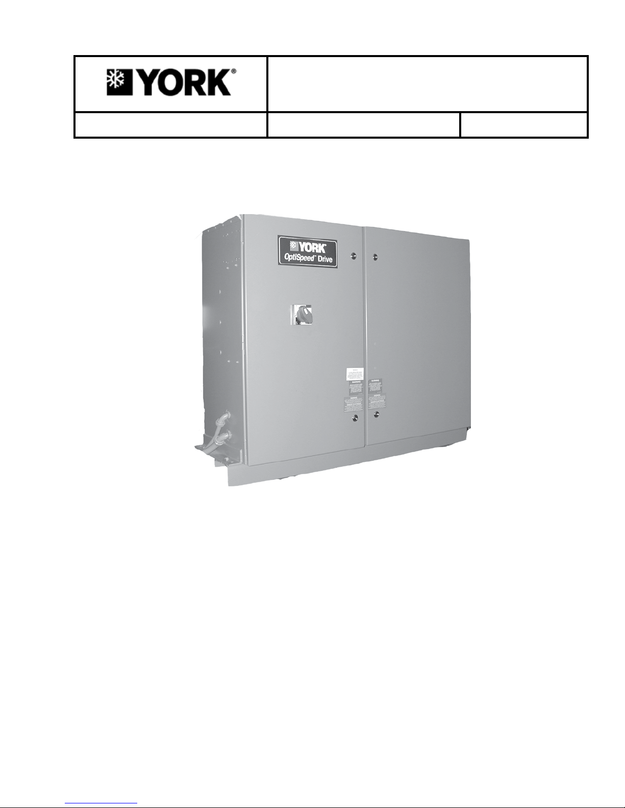
LIQUID COOLED OPTISPEED™
COMPRESSOR SPEED DRIVE
OPERATION MANUAL Supersedes: 160.00-O4 (415) Form 160.00-O4 (1217)
MODELS VSD 270, 292, 351, 385, 419, 424, 503, 608, 658, AND 704
MODELS LVD 270, 292, 351, 385, 419, 424, 503, 608, 658, 704, AND 900
00633VIP
VSD MODELS LVD MODELS
270 HP – 60 HZ, 400 VAC 270 HP – 60 HZ, 380 VAC 658 HP – 50 HZ, 400 VAC
292 HP – 50 HZ, 400 VAC 270 HP – 60 HZ, 400 VAC 704 HP – 50 HZ, 415 VAC
292 HP – 50 HZ, 415 VAC 292 HP – 50 HZ, 400 VAC 900 HP – 50 HZ, 400 VAC
351 HP – 60 HZ, 460 VAC 292 HP – 50 HZ, 415 VAC 900 HP – 50 HZ, 415 VAC
385 HP – 60 HZ, 400 VAC 351 HP – 60 HZ, 460 VAC
419 HP – 50 HZ, 400 VAC 385 HP – 60 HZ, 380 VAC
419 HP – 50 HZ, 415 VAC 385 HP – 60 HZ, 400 VAC
424 HP – 60 HZ, 575 VAC 419 HP – 50 HZ, 400 VAC
503 HP – 60 HZ, 460 VAC 419 HP – 50 HZ, 415 VAC
608 HP – 60 HZ, 575 VAC 424 HP – 60 HZ, 575 VAC
658 HP – 50 HZ, 400 VAC 503 HP – 60HZ, 460 VAC
704 HP – 50 HZ, 415 VAC 608 HP – 60HZ, 575 VAC
Issue Date:
December 19, 2017
Page 2
FORM 160.00-O4
ISSUE DATE: 12/19/2017
IMPORTANT!
READ BEFORE PROCEEDING!
GENERAL SAFETY GUIDELINES
This equipment is a relatively complicated apparatus.
During rigging, installation, operation, maintenance,
or service, individuals may be exposed to certain components or conditions including, but not limited to:
heavy objects, refrigerants, materials under pressure,
rotating components, and both high and low voltage.
Each of these items has the potential, if misused or
handled improperly, to cause bodily injury or death. It
is the obligation and responsibility of rigging, installation, and operating/service personnel to identify and
recognize these inherent hazards, protect themselves,
and proceed safely in completing their tasks. Failure
to comply with any of these requirements could result
in serious damage to the equipment and the property in
which it is situated, as well as severe personal injury or
death to themselves and people at the site.
This document is intended for use by owner-authorized
rigging, installation, and operating/service personnel. It
is expected that these individuals possess independent
training that will enable them to perform their assigned
tasks properly and safely. It is essential that, prior to
performing any task on this equipment, this individual
shall have read and understood the on-product labels,
this document and any referenced materials. This individual shall also be familiar with and comply with
all applicable industry and governmental standards and
regulations pertaining to the task in question.
SAFETY SYMBOLS
The following symbols are used in this document to alert the reader to specific situations:
Indicates a possible hazardous situation
which will result in death or serious injury
if proper care is not taken.
Identies a hazard which could lead to
damage to the machine, damage to other
equipment and/or environmental pollution if proper care is not taken or instructions and are not followed.
Indicates a potentially hazardous situation which will result in possible injuries
or damage to equipment if proper care is
not taken.
External wiring, unless specied as an optional connection in the manufacturer’s product line, is not
to be connected inside the control cabinet. Devices such as relays, switches, transducers and controls
and any external wiring must not be installed inside the micro panel. All wiring must be in accor-
dance with Johnson Controls’ published specications and must be performed only by a qualied
electrician. Johnson Controls will NOT be responsible for damage/problems resulting from improper
connections to the controls or application of improper control signals. Failure to follow this warn-
ing will void the manufacturer’s warranty and cause serious damage to property or personal injury.
2
Highlights additional information useful
to the technician in completing the work
being performed properly.
JOHNSON CONTROLS
Page 3
CHANGEABILITY OF THIS DOCUMENT
FORM 160.00-O4
ISSUE DATE: 12/19/2017
In complying with Johnson Controls’ policy for continuous product improvement, the information contained in this document is subject to change without
notice. Johnson Controls makes no commitment to
update or provide current information automatically
regarding the applicability of these documents, rigging, lifting, and operating/service personnel should
verify whether the equipment has been modified and
if current literature is available from the owner of the
equipment prior to performing any work on the chiller.
to the manual or product owner. Updated manuals, if
applicable, can be obtained by contacting the nearest
CHANGE BARS
Johnson Controls Service office or accessing the Johnson Controls QuickLIT website at http://cgproducts.
johnsoncontrols.com.
Revisions made to this document are indicated with a
line along the left or right hand column in the area the
revision was made. These revisions are to technical inIt is the responsibility of rigging, lifting, and operating/
service personnel to verify the applicability of these
formation and any other changes in spelling, grammar
or formatting are not included.
documents to the equipment. If there is any question
ASSOCIATED LITERATURE
MANUAL DESCRIPTION FORM NUMBER
Operation Manual (Unit) Model YT, (Centrifugal) 160.55-O1
Operation Manual (Unit) Model YK, (Centrifugal) 160.54-O1
Operation Manual (Control Panel) Model YT, (Centrifugal) 160.55-O1
Operation Manual (Control Panel) Model YK, (Centrifugal) 160.54-O1
Service Manual (Control Panel) Model YT, (Centrifugal) 160.55-M1
Service Manual (Control Panel) Model YK, (Centrifugal) 160.54-M1
Wiring Diagram (Control Panel) Model YT, (Centrifugal) 160.55-PW2
Wiring Diagram (Control Panel) Model YT, (Centrifugal) Model YK, (Centrifugal) 160.54-PW8
Wiring Field Connections (Variable Speed Drive) Model YT, (Centrifugal) 160.55-PW5
Wiring Field Connections (Variable Speed Drive) Model YK, (Centrifugal) 160.54-PW5
Service Manual (Control Panel) Model VSD (Variable Speed Drive) 160.00-M4
Renewal Parts (Variable Speed Drive)
160.00-RP4
(LIB-B01A-RPB-EN)
JOHNSON CONTROLS
3
Page 4
FORM 160.00-O4
ISSUE DATE: 12/19/2017
NOMENCLATURE
W
VSD351_RKFT- 46
Voltage Rating: 40= 400VAC, 60Hz
46= 460VAC, 60Hz
50= 400VAC, 50Hz
58= 575VAC, 60Hz
68= 415VAC, 50Hz
Optional 519: Filter-Installed (FT) or Not (_)
Chiller Type: YK (K), YT (T)
Retrot Package (R), Factory Package (_)
Horsepower Rating: 270, 292, 351, 385, 419, 424, 503, 608
Type of Drive
(W) Asia, (_) Global Design
OPTISPEED™ MODEL PART NUMBERS
The X in the part number below indicates which type of communications is used between the Micropanel and the
OSCD: 1 = YORK Protocol, 7 = MODBUS Protocol, 8 = MODBUS with CPC, W = Asia (W in the 4th position
taking place of the first hyphen in the part number)
TABLE 1 - VSD PART NUMBERS AND DESCRIPTIONS
PART NUMBER
60 HZ 50 HZ
270 HP
400 VAC
292 HP
400 VAC
MODEL
VSD270T-40 371-02767-X21 Factory Pack, YT Base Model
VSD270K-40 371-02767-X22 Factory Pack, YK Base Model
VSD270TFT-40 371-02767-X25 Factory Pack, YT Filter Model
VSD270KFT-40 371-02767-X26 Factory Pack, YK Filter Model
VSD270RT-40 371-02767-X31 Retrot, YT Base Model
VSD270RK-40 371-02767-X32 Retrot, YK Base Model
VSD270RTFT-40 371-02767-X35 Retrot, YT Filter Model
VSD270RKFT-40 371-02767-X36 Retrot, YK Filter Model
VSD292T-50 371-03700-X01 Factory Pack, YT Base Model
VSD292K-50 371-03700-X02 Factory Pack, YK Base Model
VSD292TFT-50 371-03700-X05 Factory Pack, YT Filter Model
VSD292KFT-50 371-03700-X06 Factory Pack, YK Filter Model
VSD292RT-50 371-03700-X11 Retrot, YT Base Model
VSD292RK-50 371-03700-X12 Retrot, YK Base Model
VSD292RTFT-50 371-03700-X15 Retrot, YT Filter Model
VSD292RKFT-50 371-03700-X16 Retrot, YK Filter Model
W-VSD292K-50 371W06040-X02 Factory Pack, YK Base Model
W-VSD292KFT-50 371W06040-X06 Factory Pack, YK Filter Model
DESCRIPTION
4
JOHNSON CONTROLS
Page 5
TABLE 1 - VSD PART NUMBERS AND DESCRIPTIONS (CONT'D)
FORM 160.00-O4
ISSUE DATE: 12/19/2017
292 HP
415 VAC
351 HP
460 VAC
385 HP
400 VAC
419 HP
400 VAC
MODEL
PART NUMBER
60 HZ 50 HZ
DESCRIPTION
VSD292T-68 371-03700-X21 Factory Pack, YT Base Model
VSD292K-68 371-03700-X22 Factory Pack, YK Base Model
VSD292TFT-68 371-03700-X25 Factory Pack, YT Filter Model
VSD292KFT-68 371-03700-X26 Factory Pack, YK Filter Model
VSD292RT-68 371-03700-X31 Retrot, YT Base Model
VSD292RK-68 371-03700-X32 Retrot, YK Base Model
VSD292RTFT-68 371-03700-X35 Retrot, YT Filter Model
VSD292RKFT-68 371-03700-X36 Retrot, YK Filter Model
W-VSD292K-68 371W06040-X22 Factory Pack, YK Base Model
W-VSD292KFT-68 371W06040-X26 Factory Pack, YK Filter Model
VSD351T-46 371-02767-X01 Factory Pack, YT Base Model
VSD351K-46 371-02767-X02 Factory Pack, YK Base Model
VSD351TFT-46 371-02767-X05 Factory Pack, YT Filter Model
VSD351TFK-46 371-02767-X06 Factory Pack, YK Filter Model
VSD351RT-46 371-02767-X11 Retrot, YT Base Model
VSD351RK-46 371-02767-X12 Retrot, YK Base Model
VSD351RTFT-46 371-02767-X15 Retrot, YT Filter Model
VSD351RTFK-46 371-02767-X16 Retrot, YK Filter Model
VSD385T-40 371-03789-X21 Factory Pack, YT Base Model
VSD385K-40 371-03789-X22 Factory Pack, YK Base Model
VSD385TFT-40 371-03789-X23 Factory Pack, YT Filter Model
VSD385KFT-40 371-03789-X24 Factory Pack, YK Filter Model
VSD385RT-40 371-03789-X31 Retrot, YT Base Model
VSD385RK-40 371-03789-X32 Retrot, YK Base Model
VSD385RTFT-40 371-03789-X33 Retrot, YT Filter Model
VSD385RKFT-40 371-03789-X34 Retrot, YK Filter Model
VSD419T-50 371-03789-X05 Factory Pack, YT Base Model
VSD419K-50 371-03789-X06 Factory Pack, YK Base Model
VSD419TFT-50 371-03789-X07 Factory Pack, YT Filter Model
VSD419KFT-50 371-03789-X08 Factory Pack, YK Filter Model
VSD419RT-50 371-03789-X15 Retrot, YT Base Model
VSD419RK-50 371-03789-X16 Retrot, YK Base Model
VSD419RTFT-50 371-03789-X17 Retrot, YT Filter Model
VSD419RKFT-50 371-03789-X18 Retrot, YK Filter Model
W-VSD419K-50 371W06431-X06 Factory Pack, YK Base Model
W-VSD419KFT-50 371W06431-X08 Factory Pack, YK Filter Model
W-VSD419T-50 371-05395-X05 Factory Pack, YT Base Model
W-VSD419K-50 371-05395-X06 Factory Pack, YK Base Model
W-VSD419TFT-50 371-05395-X07 Factory Pack, YT Filter Model
W-VSD419KFT-50 371-05395-X08 Factory Pack, YK Filter Model
W-VSD419RT-50 371-05395-X15 Retrot, YT Base Model
W-VSD419RK-50 371-05395-X16 Retrot, YK Base Model
W-VSD419RTFT-50 371-05395-X17 Retrot, YT Filter Model
W-VSD419RKFT-50 371-05395-X18 Retrot, YK Filter Model
JOHNSON CONTROLS
5
Page 6
FORM 160.00-O4
ISSUE DATE: 12/19/2017
TABLE 1 - VSD PART NUMBERS AND DESCRIPTIONS (CONT'D)
419 HP
415 VAC
424 HP
575 VAC
503 HP
460 VAC
608 HP
575 VAC
658 HP
400 VAC
704 HP
415 VAC
MODEL
PART NUMBER
60 HZ 50 HZ
DESCRIPTION
VSD419T-68 371-03789-X25 Factory Pack, YT Base Model
VSD419K-68 371-03789-X26 Factory Pack, YK Base Model
VSD419TFT-68 371-03789-X27 Factory Pack, YT Filter Model
VSD419KFT-68 371-03789-X28 Factory Pack, YK Filter Model
VSD419RT-68 371-03789-X35 Retrot, YT Base Model
VSD419RK-68 371-03789-X36 Retrot, YK Base Model
VSD419RTFT-68 371-03789-X37 Retrot, YT Filter Model
VSD419RKFT-68 371-03789-X38 Retrot, YK Filter Model
W-VSD419K-68 371W06431-X26 Factory Pack, YK Base Model
W-VSD419KFT-68 371W06431-X28 Factory Pack, YK Filter Model
VSD424T-58 371-04881-X01 Factory Pack, YT Base Model
VSD424K-58 371-04881-X02 Factory Pack, YK Base Model
VSD424TFT-58 371-04881-X03 Factory Pack, YT Filter Model
VSD424TFK-58 371-04881-X04 Factory Pack, YK Filter Model
VSD424RT-58 371-04881-X11 Retrot, YT Base Model
VSD424RK-58 371-04881-X12 Retrot, YK Base Model
VSD424RTFT-58 371-04881-X13 Retrot, YT Filter Model
VSD424RTFK-58 371-04881-X14 Retrot, YK Filter Model
VSD503T-46 371-03789-X01 Factory Pack, YT Base Model
VSD503K-46 371-03789-X02 Factory Pack, YK Base Model
VSD503TFT-46 371-03789-X03 Factory Pack, YT Filter Model
VSD503TFK-46 371-03789-X04 Factory Pack, YK Filter Model
VSD503RT-46 371-03789-X11 Retrot, YT Base Model
VSD503RK-46 371-03789-X12 Retrot, YK Base Model
VSD503RTFT-46 371-03789-X13 Retrot, YT Filter Model
VSD503RTFK-46 371-03789-X14 Retrot, YK Filter Model
VSD424T-58 371-04563-X01 Factory Pack, YT Base Model
VSD424K-58 371-04563-X02 Factory Pack, YK Base Model
VSD424TFT-58 371-04563-X03 Factory Pack, YT Filter Model
VSD424TFK-58 371-04563-X04 Factory Pack, YK Filter Model
VSD424RT-58 371-04563-X11 Retrot, YT Base Model
VSD424RK-58 371-04563-X12 Retrot, YK Base Model
VSD424RTFT-58 371-04563-X13 Retrot, YT Filter Model
VSD424RTFK-58 371-04563-X14 Retrot, YK Filter Model
W-VSD658K-50 371W06212-X02 Factory Pack, YK Base Model
W-VSD658KFT-50 371W06212-X04 Factory Pack, YK Filter Model
W-VSD704K-68 371W06212-X22 Factory Pack, YK Base Model
W-VSD704KFT-68 371W06212-X24 Factory Pack, YK Filter Model
6
JOHNSON CONTROLS
Page 7

FORM 160.00-O4
ISSUE DATE: 12/19/2017
NOMENCLATURE
LVD 0503 G R N01 K C 30 B 06 L Z - 46 A
I II III IV V VI VII VIII IX X XI XII XIII XIV
I - Drive Type
LVD
(historical models)
VSD
TM
HYP
II - Horsepower and Amp Rating
(4 digits fixed length)
III - Design Center/Source
G = Global Design
W = Asia Design
T = Toshiba
B = Benshaw
IV - VSD Mounting Method
X = Unit Mount (Factory Pack)
R = Remote Mount (Floor Standing)
V - Enclosure Type Rating
N01 = NEMA 1
N04 = NEMA4
N3R = NEMA 3R
I33 = IP33
*** = Not yet defined
VIII - Liquid DWP
15 = 150 PSIG
30 = 300 PSIG
* = Not yet defined
IX - Input Connection
D = Disconnect Switch
B = Circuit Breaker
T = Terminal Block
* = Not yet defined
X - Input Connection Rating
04 = 400A
06 = 600A
08 = 800A
10 = 1000A
12 = 1200A
00 = None (terminal block)
* = Not yet defined
XI - Code Agency Approval
L = cUL/cETL
C = CE
G =GB
Q = Special
X = None
VI - Chiller Type
H = YMC2 (YH)
K = YK
T = YT
VII - Chiller Cooling Method/VSD Cooling
Medium
C = Condenser liquid cooled / water
E = Evaporator liquid cooled / water
D = Condenser liquid cooled / glycol
F = Evaporator liquid cooled / glycol
B = Air cooled / glycol
A = Air cooled / air
R = Refrigerant / refrigerant
* = Not yet defined
JOHNSON CONTROLS
XII - Harmonic Mitigation
F = Filter Model
Z = Base Model
A = Active Front End Model
XIII - Input Voltage/Frequency
(Per M-527)
40 = 380/400V 60Hz
50 = 380/400V 50Hz
42 = 400V 60Hz
46 = 460V 60Hz
68 = 415V 50Hz
58 = 575V 60Hz
XIV - Product Mod Level Suffix
A = Mod Level "A"
B = Mod Level "B"
7
Page 8
FORM 160.00-O4
ISSUE DATE: 12/19/2017
OPTISPEED™ MODEL PART NUMBERS (CONT'D)
The X in the part number below indicates which type of communications is used between the Micropanel and the
OSCD: 1 = YORK Protocol, 7 = MODBUS Protocol, 8 = MODBUS w/ CPC, W = Asia (4th position taking place
of the first hyphen in the part number)
TABLE 2 - LVD PART NUMBERS AND DESCRIPTIONS
MODEL NUMBER PART NUMBER DESCRIPTION
270 HP – 60 HZ, 380 – 400 VAC LVD0270GXN01KC30B04LZ-40A 371-06976-X22 Factory Pack, YK Chiller
270 HP – 60 HZ, 400 VAC LVD0270GXN01KC30B04LZ-42A 371-06976-X46
292 HP – 50 HZ, 400 VAC LVD0292WXI22KC30B04GZ-50A 371W06640-X02 Factory Pack, YK Chiller
292 HP – 50 HZ, 380 – 400 VAC LVD0292GXN01KC30B04LZ-50A 371-06976-X06 Factory Pack, YK Chiller
292 HP – 50 HZ, 415 VAC LVD0292WXI22KC30B04GZ-68A 371W06640-X22 Factory Pack, YK Chiller
292 HP – 50 HZ, 415 VAC LVD0292GXN01KC30B04LZ-68A 371-06976-X26 Factory Pack, YK Chiller
351 HP – 60 HZ, 460 VAC LVD0315GXN01KC30B04LZ-46A 371-06976-X02 Factory Pack, YK Chiller
385 HP – 60 HZ, 380 – 400 VAC LVD0385GXN01KC30B06LZ-40A 371-06697-X22 Factory Pack, YK Chiller
385 HP – 60 HZ, 400 VAC LVD0385GXN01KC30B06LZ-42A 371-06697-X46 Factory Pack, YK Chiller
419 HP – 50 HZ, 380 – 400 VAC LVD0419GXN01KC30B06LZ-50A 371-06697-X06 Factory Pack, YK Chiller
419 HP – 50 HZ, 400 VAC LVD0419WXI22KC30B06GZ-50A 371W06642-X06 Factory Pack, YK Chiller
419 HP – 50 HZ, 415 VAC LVD0419WXI22KC30B06GZ-68A 371W06642-X26 Factory Pack, YK Chiller
Factory Pack, YK Chiller
(Saudi)
419 HP – 50 HZ, 415 VAC LVD0419GXN01KC30B06LZ-68A 371-06697-X26 Factory Pack, YK Chiller
424 HP – 60 HZ, 575 VAC LVD0424GXN01KC30B04LZ-58A 371-06976-X42 Factory Pack, YK Chiller
503 HP – 60 HZ, 460 VAC LVD0503GXN01KC30B06LZ-46A 371-06697-X02 Factory Pack, YK Chiller
608 HP – 60 HZ, 575 VAC LVD0608GXN01KC30B06LZ-58A 371-06697-X42 Factory Pack, YK Chiller
658 HP – 50 HZ, 400 VAC LVD0658WXI22KC30B10GZ-50A 371W06644-X02 Factory Pack, YK Chiller
704 HP – 50 HZ, 415 VAC LVD0704WXI22KC30B10GZ-68A 371W06644-X22 Factory Pack, YK Chiller
900 HP – 50 HZ, 400 VAC LVD0900WXI22KC30B12GZ-50A 371W06646-X02 Factory Pack, YK Chiller
900 HP – 50 HZ, 415 VAC LVD0900WXI22KC30B12GZ-68A 371W06646-X22 Factory Pack, YK Chiller
8
JOHNSON CONTROLS
Page 9

FORM 160.00-O4
ISSUE DATE: 12/19/2017
TABLE OF CONTENTS
GENERAL INFORMATION .................................................................................................................................... 11
Optispeed/Harmonic Filter Component Overview ......................................................................................... 11
OptiSpeed Compressor Drive 270, 292, 351 and 424 Hp .................................................................... 11
OptiSpeed Compressor Drive 385, 419, 503, 608, 658 704 and 900 Hp ............................................. 12
Harmonic Filter Option .........................................................................................................................12
Differences for the VSD and LVD model numbers: ........................................................................................13
Differences for the VSD and LVD model drives: .............................................................................................13
Optispeed Compressor Drive Control System Overview ..............................................................................13
The Control Center before 2005 ............................................................................................................13
The Control Center beginning in 2005 ..................................................................................................14
OptiSpeed and Optional Harmonic Filter Logic Control Boards ........................................................... 14
Microcomputer Control Panel VSD Related Keypad Functions ...........................................................14
OptiView Control Panel VSD Functions ...............................................................................................15
VSD Adaptive Capacity Control ...................................................................................................................... 15
Setpoint Requirements ......................................................................................................................... 15
Stability Requirements .........................................................................................................................15
Full Open Vane Operation .................................................................................................................... 15
Effects of Surge .................................................................................................................................... 15
Drive Not Reducing Speed ................................................................................................................... 16
Stability Limit Adjustment ..................................................................................................................... 16
Surge Margin Adjustment ..................................................................................................................... 16
Safety Shutdowns ..........................................................................................................................................24
General Information ..............................................................................................................................24
Motor or Starter – Current Imbalance ....................................................................................................24
VSD - 105 % Motor Current Overload ................................................................................................... 24
VSD - High Converter Heatsink Temperature .......................................................................................24
VSD - High Inverter Baseplate Temperature (270, 292, 351 and 424 Hp drives) .................................24
VSD - High Phase (X) Inverter Baseplate Temperature (385, 419, 503 and 608 Hp drives) ................25
VSD - High Phase (X) Inverter Baseplate Temperature (658, 704 and 900 Hp drives) ........................25
VSD - Precharge Lockout ......................................................................................................................25
Harmonic Filter - High Baseplate Temperature .....................................................................................25
Harmonic Filter - High Total Demand Distortion ....................................................................................25
Cycling Shutdowns ......................................................................................................................................... 26
General Information ...............................................................................................................................26
VSD - DC Bus Voltage Imbalance .........................................................................................................26
VSD - High DC Bus Voltage ..................................................................................................................26
VSD - High Internal Ambient Temperature ............................................................................................ 26
VSD - High Phase A (or B, C) Instantaneous Current ........................................................................... 27
VSD - Initialization Failed ......................................................................................................................27
VSD - Invalid Current Scale Selection ...................................................................................................27
VSD - Logic Board Power Supply .........................................................................................................27
VSD - Logic Board Processor ...............................................................................................................27
VSD - Low Converter Heatsink Temperature ........................................................................................27
VSD - Low DC Bus Voltage ...................................................................................................................27
VSD - Low Inverter Baseplate Temperature .......................................................................................... 28
VSD - Phase A (or B, C) Gate Driver .....................................................................................................28
VSD - Precharge - DC Bus Voltage Imbalance .....................................................................................28
VSD - Precharge - Low DC Bus Voltage ...............................................................................................28
VSD - Run Signal ..................................................................................................................................28
VSD - Serial Communications ............................................................................................................... 28
JOHNSON CONTROLS
9
Page 10

FORM 160.00-O4
ISSUE DATE: 12/19/2017
TABLE OF CONTENTS (CONT'D)
VSD - Single Phase Input Power ..........................................................................................................28
VSD - Stop Contacts Open ...................................................................................................................28
Harmonic Filter - 110 % Input Current Overload ................................................................................... 29
Harmonic Filter - DC Bus Voltage Imbalance ........................................................................................29
Harmonic Filter - DC Current Transformer 1(or 2) .................................................................................29
Harmonic Filter - High DC Bus Voltage .................................................................................................29
Harmonic Filter - High Phase A (or B, C) Current ..................................................................................29
Harmonic Filter - Board Or Communications ........................................................................................29
Harmonic Filter - Logic Board Power Supply ........................................................................................30
Harmonic Filter - Low DC Bus Voltage ..................................................................................................30
Harmonic Filter - Phase Locked Loop ................................................................................................... 30
Harmonic Filter - Precharge - Low DC Bus Voltage ..............................................................................30
Harmonic Filter - Run Signal .................................................................................................................30
Warning Messages .........................................................................................................................................31
General Information ...............................................................................................................................31
Warning - Vanes Uncalibrated - Fixed Speed .......................................................................................31
Warning - Harmonic Filter - Data Loss ..................................................................................................31
Warning - Harmonic Filter - Operation Inhibited ....................................................................................31
VSD Frequently Asked Questions ................................................................................................................. 32
Temperature ...................................................................................................................................................35
LIST OF FIGURES
FIGURE 1 - OptiSpeed™ System Architecture
(MODEL VSD 351 shown similar to 270, 292, 424 Models) ................................................................17
FIGURE 2 - OPTISPEED™ SYSTEM ARCHITECTURE
(MODEL LVD 419 SHOWN, SIMILAR TO 385, 503, 608, 658, 704, AND 900 MODELS) .................. 19
FIGURE 3 - OPTISPEEDTM SYStem architecture
(MODEL LVD 419 SHOWN, SIMILAR TO 385, 503, 608, 658, 704, AND 900 MODELS) .................. 19
FIGURE 4 - OPTISPEEd
TM
System architecture (MODEL VSD 503 with HARMONIC FILTER SHOWN,
SIMILAR TO 385, 419, 608 MODELS) ................................................................................................20
FIGURE 5 - VSD Logic Board (Located on Panel Door) .........................................................................................22
FIGURE 6 - SCR Trigger Board ..............................................................................................................................22
FIGURE 7 - DC BUS Isolator Board ........................................................................................................................23
FIGURE 8 - Gate driver board and power module ..................................................................................................23
LIST OF TABLES
TABLE 1 - VSD Part Numbers And Descriptions ......................................................................................................4
TABLE 2 - LVD Part Numbers And Descriptions ....................................................................................................... 8
TABLE 3 - Safety Shutdowns ..................................................................................................................................24
TABLE 4 - Cycling Shutdown Message ..................................................................................................................26
TABLE 5 - Warning Messages ................................................................................................................................31
TABLE 6 - SI Metric Conversion .............................................................................................................................35
10
JOHNSON CONTROLS
Page 11
GENERAL INFORMATION
FORM 160.00-O4
ISSUE DATE: 12/19/2017
This instruction is to be used in conjunction with the
Operation Instructions for YORK Centrifugal chillers
furnished with an optional OptiSpeed™ Compressor
Drive (OSCD).
OPTISPEED/HARMONIC FILTER COMPONENT
OVERVIEW
OptiSpeed Compressor Drive 270, 292, 351
and 424 Hp
The YORK® OptiSpeed Compressor Drive (OSCD) is
a liquid cooled, transistorized, PWM inverter in a highly integrated package. This package is small enough
to mount directly onto the chiller motor, and small
enough to be applied in many retrofit chiller applications. The power section of the drive is composed of
four major blocks: an AC to DC rectifier section with
an integrated pre-charge circuit, a DC bus filter section, a three phase DC to AC inverter section and an
output suppression network.
An electronic circuit breaker with ground fault sensing connects the AC line to an AC line inductor and
then to the DC converter. The line inductor will limit
the amount of fault current so that the electronic circuit
breaker is sufficient for protecting the OSCD. Input
fuses to the OSCD are no longer needed. The following description of operation is specific for the 351 Hp
OSCD unless otherwise noted.
The AC to DC converter uses 3 Silicon Controlled
Rectifiers (SCR’s) and 3 diodes. One SCR and one diode are contained in each module. Three modules are
required to converter the 3 phase input AC voltage into
DC voltage. The modules are mounted on the bottom
of the liquid cooled heatsink. The use of the SCR’s in
the converter permits pre-charge of the DC bus capacitors when the chiller enters the prelube cycle, and it
also provides a fast disconnect from the AC line when
the chiller enters the coastdown cycle. At this time, the
OSCD is turned off, the SCR’s in the converter are no
longer turned on and remain in a turned off condition
until the next pre-charge cycle. The DC bus capacitors
will start to discharge through the bleeder resistors.
When the chiller enters the prelube cycle, the OSCD is
commanded to pre-charge and the SCR’s are gradually
turned on to slowly charge the DC bus capacitors. This
is called the pre-charge period, which last for 20-seconds. At this time the SCR’s are fully turned on. The
SCR Trigger board provides the turn on commands for
the SCR’s. The OSCD Logic board provides the command to the SCR trigger board when to precharge.
Although many of these parts are similar
to the parts used in previous Variable
Speed Drive (VSD) designs, these parts
are only compatible with drives having the
base part numbers included on the cover
of this form. Failure to use the correct
parts may cause major damage to these
and other components in the drive. For
example, the VSD logic board 031-02077000 used in this drive is not compatible
with 031-01433-000 logic board used in
previous designs. A new VSD logic board
was designed in 2006. The part number
of the new board is 031-02506-002. The
part number of the new board for the
575 VAC application is 031-02506-003.
The software is not interchangeable between the 575 VAC version and all other
applications. Also the software is not
interchangeable between the 031-01433,
031-02077, or the 031-02506 boards.
The DC Bus filter section of the drive consists of one
basic component, a series of electrolytic filter capacitors. The capacitors provide a large energy reservoir
for use by the DC to AC inverter section of the OSCD.
The capacitors are contained in the OSCD Power Unit.
“Bleeder” resistors are mounted on the side of the
Power Unit to provide a discharge path for the stored
energy in the capacitors.
The DC to AC inverter section of the OSCD serves
to convert the DC voltage to AC voltage at the proper
magnitude and frequency as commanded by the OSCD
Logic board. The inverter section is actually composed
of one power unit. This power unit contains one very
fast switching transistor module mounted on the same
liquid cooled heatsink as the converter modules, the
DC Bus capacitors, and an OSCD Gate Driver board.
The gate driver board provides the turn on and turn off
commands to the output transistors. The OptiSpeed
Compressor Drive Logic board determines when the
turn on and turn off commands should occur. The gate
driver board is mounted directly on top of the transistor
module, and it is held in place with mounting screws
and soldered to the transistor module.
JOHNSON CONTROLS
11
Page 12

FORM 160.00-O4
ISSUE DATE: 12/19/2017
The OSCD output suppression network is composed
of a series of capacitors and resistors. The job of the
suppressor network is to increase the time it takes for
the output voltage to switch as seen by the motor, and
reduce the peak voltage applied to the motor windings.
This network protects the compressor motor from problems commonly associated with PWM motor drives.
Other sensors and boards are used to provide safe operation of the OptiSpeed Compressor Drive. The transistor module and heatsink have thermistors mounted on
them to provide temperature information to the OSCD
logic board. These sensors protect the OSCD from over
temperature conditions. A Bus Voltage Isolator board is
used to ensure that the DC bus capacitors are properly
charged. Three output current transformers protect the
OSCD and motor from over current conditions.
OptiSpeed Compressor Drive 385, 419, 503,
608, 658 704 and 900 Hp
The 385, 419, 503, 608, 658, 704 and 900 Hp OSCD’s
function in the same manner as the 270, 292, 351 and
424 Hp and have the same basic components. The
power requirements of these higher horse power drives
require more capacitors in the DC Bus and 3 output
transistor sections are needed. One section is used for
each output phase. Each transistor module within the
output transistor section contains a thermistor, which is
connected to the OSCD logic board. The transistor gate
driver board is mounted on top of the transistor section
in the same manner as the lower horsepower model,
but it only contains 2 transistor drivers. The modules
and the boards are not interchangeable between the
270, 292, 351 and 424, and 419, 503, 608, 658, 704
and 900 Hp drives.
Harmonic Filter Option
The VSD model of OptiSpeed Compressor Drive
(OSCD) system may also include an optional harmonic filter and high frequency trap designed to meet the
IEEE Std 519, “IEEE Recommended Practices and Requirements for Harmonic Control in Electrical Power
Systems”. The harmonic filter is offered as a means
to improve the input current waveform drawn by the
OSCD from the AC line, thus reducing the possibility of causing electrical interference with other sensitive electronic equipment connected to the same power
source. An additional benefit of the optional harmonic
filter is that it will correct the system power factor to
nearly unity.
The power section of the Harmonic Filter is composed
of three major blocks: a pre-charge section, a three
phase inductor and a Filter Power Unit.
The pre-charge section contains pre-charge resistors, a
pre-charge contactor and a supply contactor. The precharge network serves two purposes, to slowly charge
the DC bus capacitors associated with the Filter Power
Unit, and to provide a means of disconnecting the filter power unit from the AC line. When the chiller is
turned off, both contactors are de-energized and the filter power unit is disconnected from the AC line. When
the chiller starts to run, the pre-charge resistors are
switched into the circuit via the precharge contactor for
a fixed time period of 5 seconds. This permits the filter capacitors in the filter power unit to slowly charge.
After the 5-second time period, the supply contactor is
energized and the pre-charge contactor is de-energized,
permitting the filter power unit to completely charge.
Three power fuses connect the filter power components to the AC line. Very fast semiconductor power
fuses are utilized to ensure that the transistor module
does not rupture if a catastrophic failure were to occur
on the DC bus of the filter power unit.
The three phase inductor provides some impedance for
the filter to “work against”. It effectively limits the rate
of change in current at the input to the filter to a reasonable level.
The Filter Power Unit is the most complicated power
component in the optional filter. Its purpose is to generate the harmonic currents required by the OSCD’s
AC-to-DC converter so that these harmonic currents
are not drawn from the AC line. The Filter Power Unit
is identical to the OSCD's Power Unit in the 351 Hp
drive, except for 2 less capacitors in the filter capacitor
“bank”, and a smaller transistor module and modified
gate driver board. The Harmonic Filter Gate Driver
board provides turn on and turn off commands as determined by the Harmonic Filter Logic board. “Bleeder”
resistors are mounted on the side of the Filter Power
Unit to provide a discharge path for the DC bus capacitors.
Other sensors and boards are used to provide safe operation of the harmonic filter. The transistor module
contains a temperature sensor that provides temperature information back to the Filter Logic Board. This
sensor protects the filter transistor module from over
temperature conditions. A Bus Isolator board is used to
ensure that the DC bus capacitors are properly charged
and that the voltage is balanced. Two output current
12
JOHNSON CONTROLS
Page 13

FORM 160.00-O4
ISSUE DATE: 12/19/2017
sensors are used to protect the filter against an over
current or an overload condition. Input current transformers sense the input current drawn by the OSCD’s
AC to DC converter. The Line Voltage Isolation board
provides AC line voltage information to the Harmonic
Filter Logic board. This information is used to determine the proper bus voltage value.
The “trap” filter is standard on all OSCD's that contain
an optional Harmonic Filter. The “trap” filter is composed of a series of capacitors, inductors, and resistors.
The “trap” filter is used to reduce the effects of the
PWM switching frequency of the filter.
DIFFERENCES FOR THE VSD AND LVD
MODEL NUMBERS:
Within the drive model number nomenclature there are
2 different letters for the design center of the drive. A
‘G’ for the design center is a drive that is designed to
the UL and CE requirements. A ‘W’ for the design center is a drive that is designed to standards that govern
products built for the Asia market. The way the drive
functions, protects itself, and the motor are the same
for both designs. The ‘W’ design takes advantage of
local components, and local manufacturing. The cooling system is the area where most of the changes occur
and only effect the 50 Hz application. The ‘W’ design
solves the problem of reduce cooling because of 50
Hz power by using a large cooling fan and a different
cooling pump. The cooling fan and pump require a 230
VAC 50 Hz source. This higher power source allows
the fan and pump to provide the same amount of cooling as the 60 Hz application. The 230 VAC source is
provided by an additional voltage tap from the control
transformer. This new transformer provides the voltage
required for the 230 VAC and 120 VAC components.
DIFFERENCES FOR THE VSD AND LVD
MODEL DRIVES:
The VSD model drives are designed so that the harmonic filter system can be included in the drive enclosure. The VSD model also contains the control wiring,
additional cooling capacity, and pre-charge resistors for
the harmonic filter system, regardless if the harmonic
filter system is installed or not. This process allowed
for an easier method to retrofit the harmonic filter system later if the customer desired. The LVD model does
not contain any support for the harmonic filter system.
The enclosure size is reduced, and the harmonic filter
cannot be added as an option later. The function of the
drive is identical between the 2 designs.
OPTISPEED COMPRESSOR DRIVE CONTROL
SYSTEM OVERVIEW
The OSCD control system can be connected to a Microcomputer Control Center or to an OptiView Control
Center. Regardless of which control center is used each
component performs the same function.
The OSCD control system is composed of various
components located within both the Control Center
and the OSCD. Thus integrating the Control Center
with the OSCD. The OSCD system utilizes various
microprocessors, which are linked together through a
network of communications links.
The Control Center before 2005
The Control Center contains two boards that act upon
OSCD related information, the Microboard and the
Adaptive Capacity Control board (ACC). The ACC
board performs two major functions in the OSCD control system - (1) to act as a gateway for information
flow between the Control Center and the OSCD. (2) To
determine the optimum operating speed for maximum
chiller system efficiency.
The ACC board acts as an information gateway for all
data flowing between the OSCD and the Control Center. The ACC board has a communication link to the
OSCD logic board, and one communication link from
the optional Harmonic Filter logic board. Once the
ACC board receives the information, the information
is then passed onto the Control Center via a software
communication link. The Microcomputer Control Center communicates in a parallel fashion via two ribbon
cables connecting the ACC board to the Microboard.
The OptiView™ Control Center communicates
through communications port via a bi-directional serial
port via a three wire cable connecting the ACC board
to the Microboard.
In order to achieve the most efficient operation of a centrifugal compressor, the speed of the compressor must
be reduced to match the “lift” or “head” of the load.
This “lift” or “head” is determined by the evaporator
and condenser refrigerant pressures. However, if the
compressor speed is reduced too much, the refrigerant
gas will flow backwards through the compressor wheel
causing the compressor to “surge”, an undesirable and
extremely inefficient operating condition. Thus there
exists one particular optimum operating speed (on the
“edge” of surge) for a given head, which provides the
optimum system efficiency.
JOHNSON CONTROLS
13
Page 14

FORM 160.00-O4
ISSUE DATE: 12/19/2017
The compressor’s inlet guide vanes, which are used
in fixed speed applications to control the amount of
refrigerant gas flowing through the compressor, are
controlled together with the compressor speed on an
OSCD chiller system to obtain the required chilled liquid temperature while simultaneously requiring minimum power from the AC line.
The ACC board automatically generates its own
“Adaptive” three-dimensional surge surface map while
the chiller system is in operation. This “Adaptive” operation is accomplished through the use of a patented
surge detection algorithm. The novel surge detection
system utilizes pressure information obtained from the
chiller’s two pressure transducers or the OSCD’s instantaneous power output to determine if the system
is in “surge”. Thus the adaptive system permits construction of a customized compressor map for each individual chiller system. Benefits of this new adaptive
system include: (1) a customized compressor map for
each chiller which eliminates inefficient operation due
to the safety margin built into the previous designs to
compensate for compressor manufacturing tolerances
(2) the ability to update the system’s surge surface as
the unit ages and (3) automatic updating of the compressor map if changes in refrigerant are implemented
at a later date.
OptiSpeed and Optional Harmonic Filter Logic
Control Boards
Within the enclosure of the VSD model drive, the
OSCD logic board and optional Harmonic Filter logic board are interconnected via a 16-position ribbon
cable. This cable provides power for the Filter logic
board and a method of communications between the
two boards.
The OSCD Logic board performs numerous functions,
control of the OSCD’s cooling fans and pumps, when
to pre-charge the bus capacitors, and generates the
PWM.
The OSCD Logic board also determines shutdown
conditions by monitoring the three phases of motor
current, heatsink temperature, baseplate temperature,
internal ambient temperature, and the DC bus voltage.
The optional Harmonic Filter logic board determines
when to precharge the harmonic filter power unit, when
to switch the transistors in the harmonic filter power
unit, and collects data to determine power calculations.
This board also uses this data to determine shutdown
conditions.
Microcomputer Control Panel VSD Related
Keypad Functions
The Control Center beginning in 2005
A major change in the control system took place in
2005. Several redesigns took place in the OptiView
panel and the OSCD. The redesign replaced microprocessors that were becoming obsolete. This was a
time to take advantage of new components that were
now available. An additional communications port was
added so that the communications between the microboard and the OSCD logic board was faster. In the
changes to the microboard the function of the Adaptive
Capacity Board was placed into the microboard, and
the ACC board was longer needed in new production.
The new microboard is also compatible with the older
designs microboards used in the OptiView panel. The
new OSCD logic also added this new communication
port, but also retained all of the functions required to
still communicate with the ACC board.
Refer to 160.00-M4 for related keypad functions.
Some of the displayed data in this form is different
from the 160.00-M1. Under the Options Key – the
following changes will be displayed:
VSD PHASE A INVERTER HEATSINK TEMP = ___°F.
VSD PHASE B INVERTER HEATSINK TEMP = ___°F.
VSD PHASE C INVERTER HEATSINK TEMP = ___°F.
These three temperature values are replaced with:
VSD BASEPLATE TEMP = ___°F
For the 270, 292, 351 and 424 Hp drives. The 385, 419,
503, 608, 658, 704 and 900 Hp drives will display 3
phases of Baseplate temperature. When the Filter is
present the following data will change.
FILTER HEATSINK TEMP = ___°F.
This temperature data will now be called.
FILTER BASEPLATE TEMP = ___°F.
14
JOHNSON CONTROLS
Page 15

FORM 160.00-O4
ISSUE DATE: 12/19/2017
The names for the above data were changed because
the temperature sensor is now inside the transistor
module instead of the chill plate where the transistor
modules are mounted. This new sensor gives a better
indication of true temperature of the power electronics.
OptiView Control Panel VSD Functions
Refer to the specific OptiView™ Control Panel service
book for detailed information. All of the OSCD related
information is contained under the Motor and Compressor Screens.
VSD ADAPTIVE CAPACITY CONTROL
The YORK® OptiSpeed™ Compressor Drive utilizes
a different approach to speed reduction compared to
earlier variable speed products. There is no longer a
pre-programmed surge map – the YORK® adaptive
system experiments with the speed and vanes to find
the optimum speed for any given condition. It does not
always encounter a “Surge” in the process, but when
it does, the Adaptive Capacity Control (ACC) stores
into memory, the conditions surrounding the Surge,
and therefore remembers to avoid the stored operating
point anytime in the future.
Early versions of the ACC software required that the
drive always start and run up to full speed. ACC software starting with version C.ACC.01.04 applies a new
slow ramp up of the drive speed. This new software
lowers the peak current demand from the drive during
start up, saves additional energy, and reduces the possibility of the chiller running in a stall condition.
The new software will ramp the drive speed up to 30
Hz quickly, and then takes 5 minutes to ramp up to 60
Hz. During this slow ramp up period the vanes will
open to meet the cooling demand. If the leaving chilled
liquid temperature is within +0.5 or lower of the leaving chilled liquid temperature setpoint, then the drive
speed will stop increasing speed and start to search for
a surge map point. On extremely hot days the chiller
may surge during the slow ramp period. The new software has a method to limit the surging. If 2 surges were
to occur during the slow ramp period, then the speed of
the drive will increase to 60 Hz.
Now that the ACC function is provided by the microboard in the OptiView panel future control changes
will be covered by the operation manual for the chiller
model of interest. All versions of software require that
two conditions be met for speed reduction to occur.
These two conditions are:
Setpoint Requirements
The leaving chilled liquid temperature must be
within +0.5 °F or lower from the leaving chilled
liquid temperature setpoint. A programmable value is now available through the OptiView panel
on software versions C.OPT.01.21.307 for the YK
chiller. This programmable value is not available
on the YT chiller. Speed reduction will not occur
until the leaving chilled liquid temperature reaches this range.
Stability Requirements
The leaving chilled liquid temperature must be
stable. Lack of stability will be indicative of the
vanes hunting, the leaving chilled liquid temperature varying, and the green LED on the ACC will
be on. Once the above conditions are met, the ACC
may begin to lower the speed of the compressor
motor 1/10 of a hertz at a time. As the ACC lowers
the speed, the leaving chilled liquid temperature
will begin to creep up. As this occurs, the control center will begin to open the vanes slightly,
just enough to maintain the leaving chilled liquid
temperature within +/- 0.5°F of the leaving chilled
liquid temperature setpoint. The ACC will continue to lower speed, with the leaving chilled liquid
temperature control in turn driving the vanes to
a more open position. This process will continue
until one of three following situations occur. This
setting is no longer available after software version C.OPT.01.21.307 for the YK chiller.
Full Open Vane Operation
Once the vanes reach the full open position, the ACC
knows it can no longer reduce speed and maintain the
leaving chilled liquid temperature setpoint. The ACC
will maintain operation at this point, with the vanes full
open, and the speed at the last point reached when the
vanes hit 100%. If there is an increase in load while at
this point, the ACC will increase speed until the vanes
are closed to 95% of open. The ACC will then be allowed to continue to reduce speed again.
Effects of Surge
If in the process of reducing speed and opening vanes
the compressor should surge, the ACC will boost the
speed up by 0.8 Hz. The ACC will store in memory a
value that represents the ratio of condenser pressure to
evaporator pressure, the vane position, and the speed of
the drive. The ratio of condenser pressure to evaporator
pressure is displayed as Delta P/P on the Control Panel.
JOHNSON CONTROLS
15
Page 16

FORM 160.00-O4
ISSUE DATE: 12/19/2017
The ACC will then know not to reduce speed this low
again, if the same delta pressure, and the vane position conditions are encounter again in the future. As
the chiller encounters various conditions, which result
in surge, it will store more points, and eventually this
storing of points creates a “Surge Map”. Surge may be
detected in two ways, by monitoring the pressure differential across the compressor, or by monitoring the
compressor motor current. Either detection will light
the Red LED on the ACC, indicating a surge was detected. The chiller may surge 6 to 8 times before the
ACC can raise the speed enough to get the chiller back
out of surge. Each surge is counted on the surge counter, which may be viewed on the control center. This
surge counter will always display the total number of
surges encountered by the chiller as determined by the
ACC. Surging which occurs at fixed speed will increment the surge counter as well, but only surges that
occur when speed reduction is possible are recorded in
the surge map.
Drive Not Reducing Speed
The ACC may begin the process of reducing speed, but
may stop speed reduction if instability is encountered.
This is the same instability discussed as one of the two
conditions which must be met to begin reducing speed
initially (See “Stability Requirements”). Once the system again becomes unstable, no additional speed reduction can occur.
• Rapid changes to chilled or condenser liquid ow.
• Valves on air-handler coils closing rapidly causing changes in heat-load.
• Extremely short chilled liquid loop.
• Parallel chiller with poor control is causing temperature variations.
• Parallel Chiller with poor control of chilled or
condenser water ows.
• Improper evaporator refrigerant level.
If you experience a problem with an OSCD not reducing speed at all, make certain the system is not
in manual speed control, or locked into fixed speed.
Either situation will cause the chiller to maintain full
speed. If the OSCD is reducing speed, but not running
as slow as you expect it should, it is likely because it is
either in an unstable condition, or running just above
a mapped surge point. As described above, the chiller must achieve stability, which is evidenced by the
Green LED being extinguished, before speed reduction will commence. Instability will cause the Green
LED to be illuminated.
Stability Limit Adjustment
Stability Limit Adjustment allows the system to properly function with larger amounts of temperature instability. Consult YORK Service to make this adjustment.
The most common causes for instability are:
• High Condenser liquid temperature.
• Dirty Condenser tubes.
• Chillers with very light loads.
Surge Margin Adjustment
Surge Margin Adjustment allows the Service Technician to increase the speed of the drive for all mapped
surge points. This parameter is rarely used, and it decreases the efficiency of the OSCD chiller system.
16
JOHNSON CONTROLS
Page 17
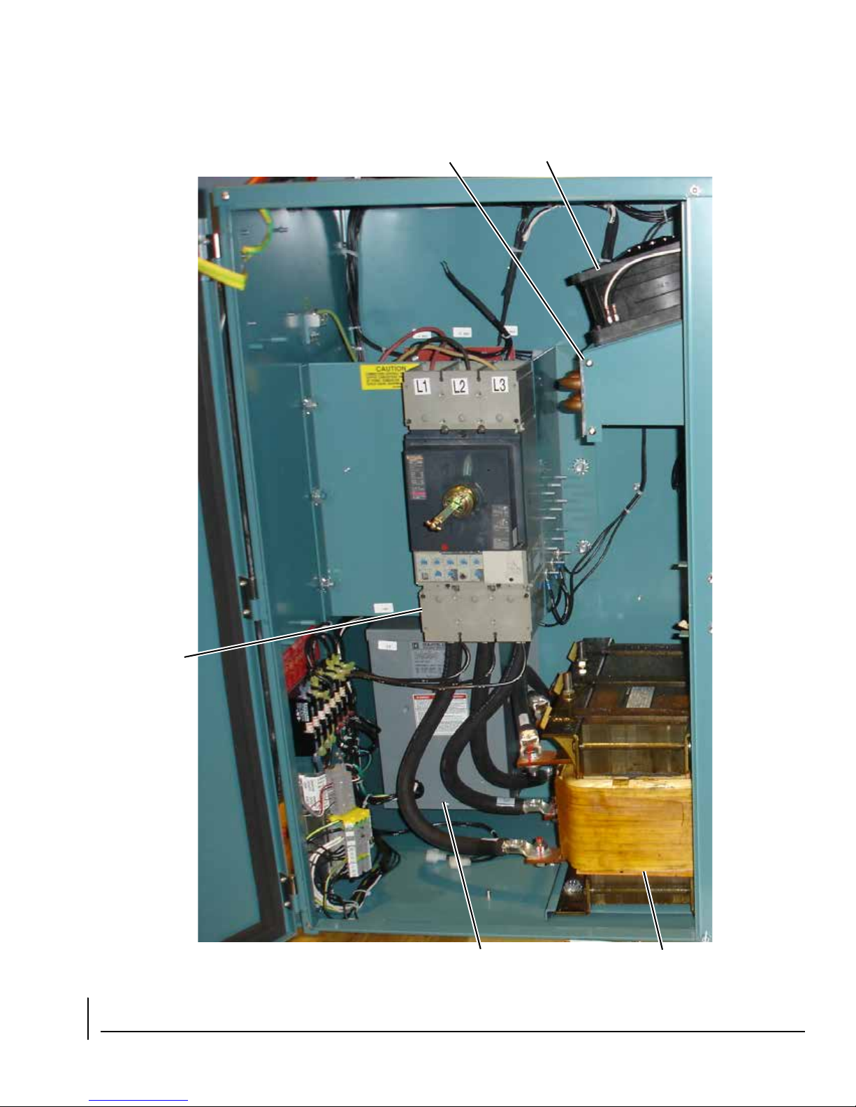
FORM 160.00-O4
ISSUE DATE: 12/19/2017
COOLING
COIL
COOLING
FANS
INPUT
BREAKER
CONTROL
TRANSFORMER
FIGURE 1 - OPTISPEED™ SYSTEM ARCHITECTURE
(MODEL VSD 351 SHOWN SIMILAR TO 270, 292, 424 MODELS)
INDUCTOR
LD13164
JOHNSON CONTROLS
17
Page 18
FORM 160.00-O4
ISSUE DATE: 12/19/2017
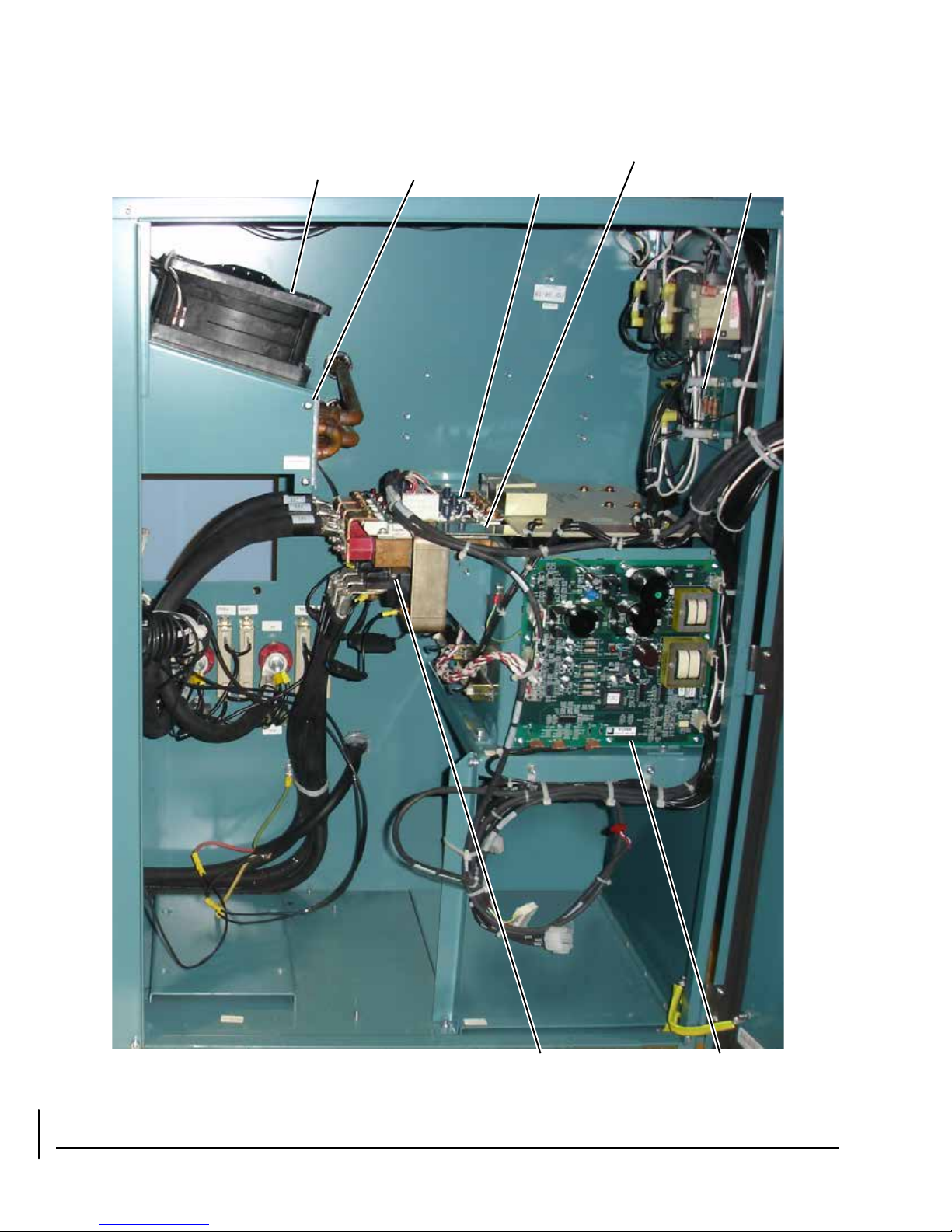
COOLING
FANS
COOLING
COIL
GATE
DRIVER
BOARD
IGBT DC BUS
ISOLATOR
BOARD
FIGURE 1 - OPTISPEED™ SYSTEM ARCHITECTURE
(MODEL VSD 351 SHOWN SIMILAR TO 270, 292, 424 MODELS) (CONT'D)
18
SCR/DIODE
MODULE
SCR
TRIGGER
BOARD
JOHNSON CONTROLS
LD13165
Page 19
FORM 160.00-O4
ISSUE DATE: 12/19/2017
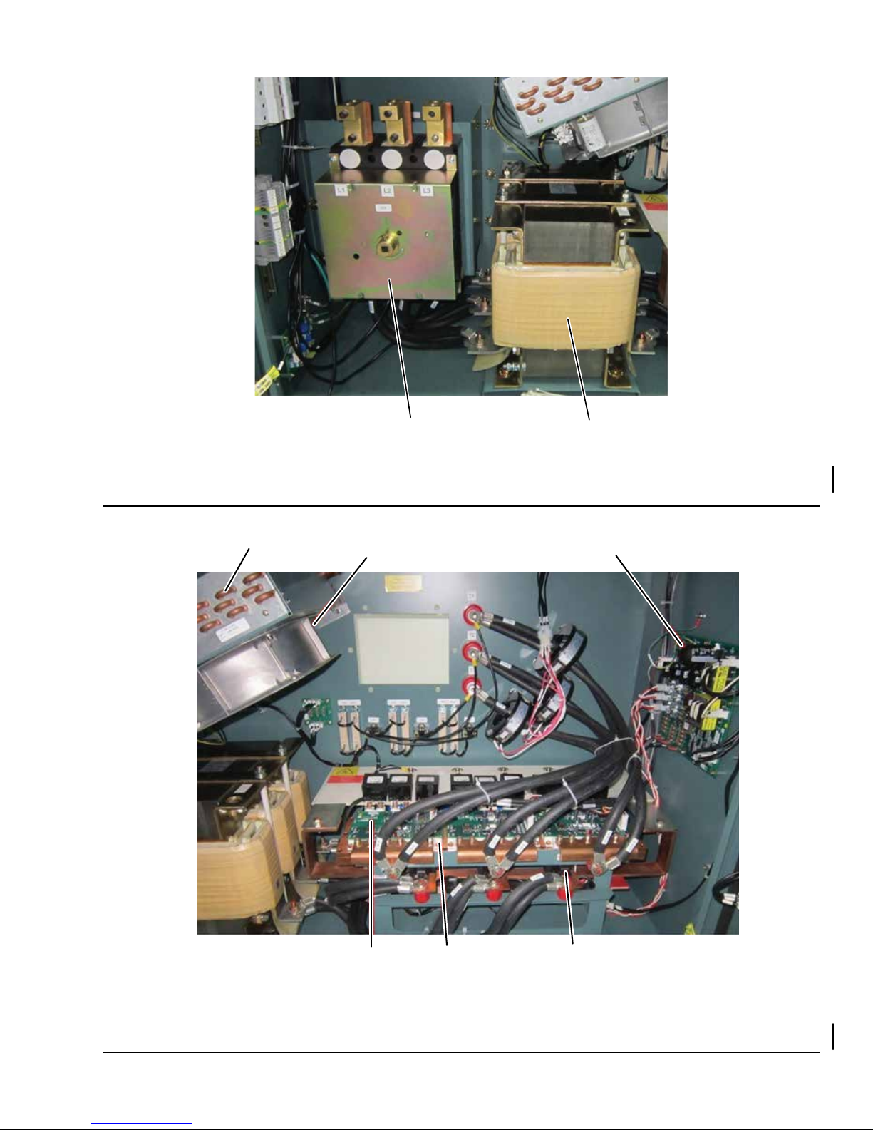
INPUT BREAKER
INDUCTOR
LD19198
FIGURE 2 - OPTISPEED™ SYSTEM ARCHITECTURE
(MODEL LVD 419 SHOWN, SIMILAR TO 385, 503, 608, 658, 704, AND 900 MODELS)
COOLING COIL
COOLING FAN
SCR TRIGGER BOARD
FIGURE 3 - OPTISPEEDTM SYSTEM ARCHITECTURE
(MODEL LVD 419 SHOWN, SIMILAR TO 385, 503, 608, 658, 704, AND 900 MODELS)
JOHNSON CONTROLS
GATE DRIVER
BOARD
IGBT
MODULE
SCR/DIODE
MODULE
LD19199
19
Page 20
FORM 160.00-O4
LD23371
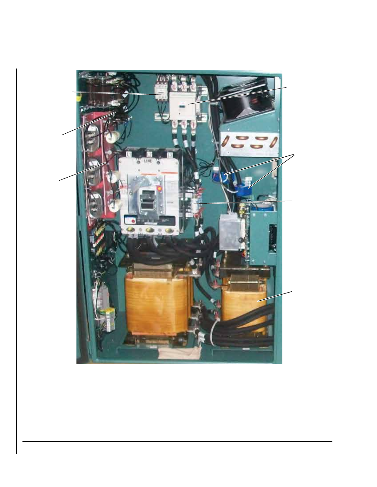
FILTER
INDUCTOR
FILTER
ISSUES
DCCT’S
FILTER
SUPPLY
CONTRACTOR
FILTER
PRE-CHARGE
CONTRACTOR
FILTER
PRE-CHARGE
RESISTORS
FILTER
TRAP ASSEMBLY
ISSUE DATE: 12/19/2017
FIGURE 4 - OPTISPEED
TM
SYSTEM ARCHITECTURE (MODEL VSD 503 WITH HARMONIC FILTER SHOWN,
SIMILAR TO 385, 419, 608 MODELS)
20
JOHNSON CONTROLS
Page 21
FORM 160.00-O4
ISSUE DATE: 12/19/2017
LINE VOLTAGE
ISOLATION
BOARD
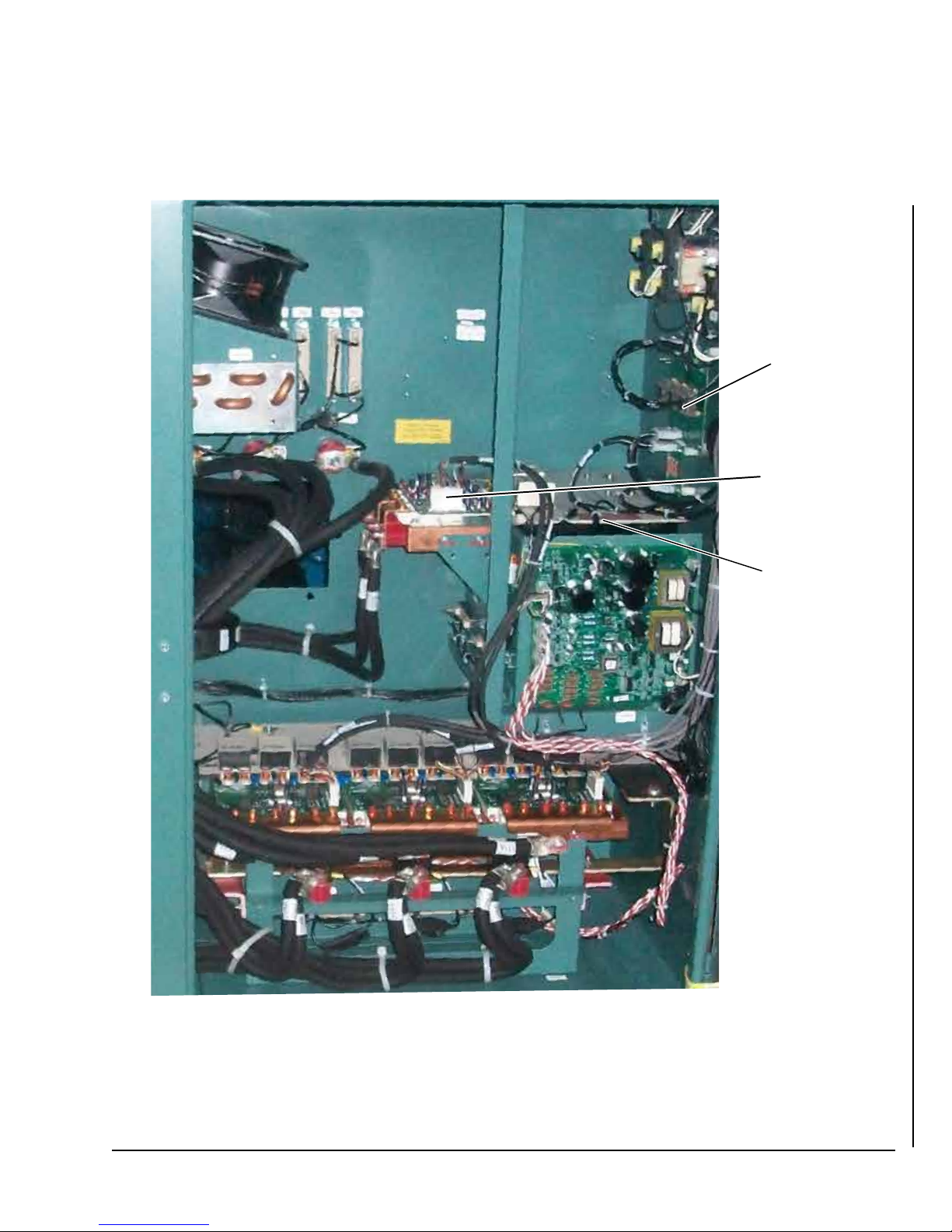
FILTER POWER
MODULE
LD23372
FILTER POWER
UNIT
FIGURE 4 - OPTISPEEDTM SYSTEM ARCHITECTURE (MODEL VSD 503 WITH HARMONIC FILTER SHOWN,
SIMILAR TO 385, 419, 608 MODELS) (CONT'D)
JOHNSON CONTROLS
21
Page 22
FORM 160.00-O4
ISSUE DATE: 12/19/2017
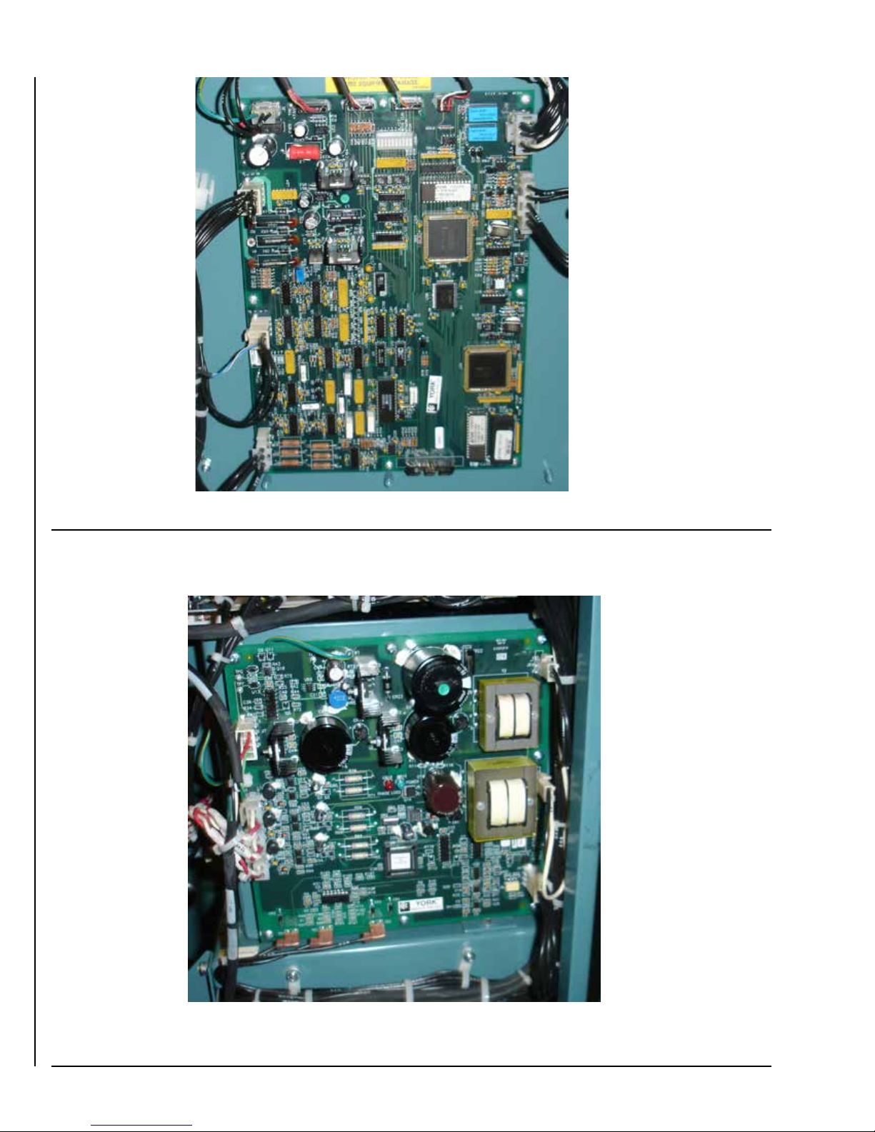
FIGURE 5 - VSD LOGIC BOARD (LOCATED ON PANEL DOOR)
LD13165
FIGURE 6 - SCR TRIGGER BOARD
22
LD13166
JOHNSON CONTROLS
Page 23
FORM 160.00-O4
ISSUE DATE: 12/19/2017
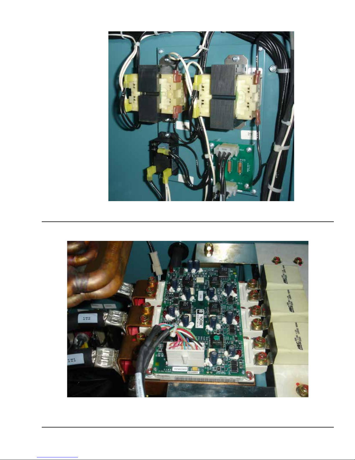
FIGURE 7 - DC BUS ISOLATOR BOARD
LD13167
FIGURE 8 - GATE DRIVER BOARD AND POWER MODULE
JOHNSON CONTROLS
LD13168
23
Page 24
FORM 160.00-O4
ISSUE DATE: 12/19/2017
SAFETY SHUTDOWNS
General Information
The Shutdowns are organized in alphabetical order
based on the OptiView™ Control Center messages.
The Microcomputer Control Center messages are also
included under these headings.
Whenever a Safety Shutdown is generated by the
OSCD or Harmonic Filter Logic Board, a series of
events will occur.
• If the chiller is not running at the time of the shutdown, the OSCD Logic Board will not turn on the
gate drivers.
• The K1 relay on the OSCD logic board will deenergize to indicate to the Control Center that the
OSCD has shutdown. The K1 relay will remain
de-energized until the cause of the shutdown has
been corrected.
• If the chiller is running at the time of the shutdown, the Control Center will start a coastdown
period (150 seconds for centrifugal chillers or
shorter for those chillers that contain the optional
“Quick Start” feature).
• The message “VSD Shutdown - Requesting Fault
Data”...will be displayed when the Control Center
is requesting the fault data from the OSCD.
• The OSCD or Harmonic Filter Logic Board will
send a shutdown code via the communications
link to the Control Center. The Micro Board will
interpret the shutdown code and display a shutdown message on the display of the Control Center.
After the coastdown period has timed out, the chiller
may be restarted if the shutdown is no longer active.
Place the Compressor Switch in the Stop/Reset position, and then into the Start position and release. The
chiller will start if no faults are active.
TABLE 3 - SAFETY SHUTDOWNS
MESSAGE DESCRIPTION
Motor or Starter – Current
Imbalance
MOTOR OR STARTER – CURRENT
IMBALANCE
VSD - 105 % Motor Current
Overload
105% MOTOR CURRENT OVERLOAD
VSD - High Converter
Heatsink Temperature
HIGH CONVERTER HEATSINK TEMP
VSD - High Inverter Baseplate
Temperature (270, 292, 351
and 424 Hp drives)
HIGH INVERTER BASEPLATE
TEMPERATURE FLT
The OSCD logic board generates this shutdown. This shutdown will become active
when the highest of the three motor currents exceeds 80% of the programmed
FLA. After these conditions are met, if any one phase of motor current exceeds
30% of the average current for 45 seconds, a Safety shutdown will be activated.
The OSCD logic board generates this shutdown by reading the current from the
3 output current transformers. The shutdown is generated when the OSCD logic
board has detected that the highest of the three output phase currents has exceeded 105% of the programmed 100% full load amps (FLA) value for more than
40 seconds. This shutdown requires a manual reset via the Reset push-button on
the OSCD logic board.
A thermistor sensor is located of the copper chill plate of the OSCD Power Unit. If
at anytime this thermistor detects a temperature of 170°F (76°C) or higher a shutdown will occur. The cooling fans and coolant pump on the OSCD will continue to
run after the shutdown until the thermistor temperature has dropped below 160°F
(71°C). This shutdown requires a manual reset via the Reset push-button on the
OSCD logic board.
A thermistor sensor is located inside the transistor module on the OSCD power
unit. If at anytime this thermistor detects a temperature of 175°F (79°C) or higher a
shutdown will occur. The cooling fans and coolant pump on the OSCD will continue to run after the shutdown until the thermistor temperature has dropped below
165°F (74°C). This shutdown requires a manual reset via the Reset push-button on
the OSCD logic board.
24
JOHNSON CONTROLS
Page 25
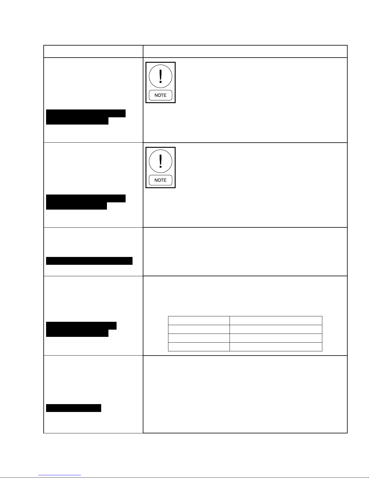
TABLE 3 - SAFETY SHUTDOWNS (CONT'D)
MESSAGE DESCRIPTION
FORM 160.00-O4
ISSUE DATE: 12/19/2017
VSD - High Phase (X) Inverter
Baseplate Temperature (385,
419, 503 and 608 Hp drives)
HIGH PHASE (X) BASEPLATE
TEMPERATURE FAULT
VSD - High Phase (X) Inverter
Baseplate Temperature (658,
704 and 900 Hp drives)
HIGH PHASE (X) BASEPLATE
TEMPERATURE FAULT
VSD - Precharge Lockout
PRE-CHARGE FAULT LOCKOUT
The X will indicate
the phase that the
high temperature
has occurred.
The X will indicate
the phase that the
high temperature
has occurred.
If the OSCD fails to meet the pre-charge criteria (refer to pre-charge faults), the
pre-charge circuit will wait for a period of 10 seconds before another pre-charge
attempt. The unit’s cooling fans and coolant pump shall remain energized during
this time period. Following this 10-second period, the pre-charge shall again be
initiated. The unit shall attempt to meet the pre-charge criteria three consecutive
times before the OCSD will shutdown, lockout, and display this message.
A thermistor sensor is located inside the
transistor module on the OSCD power unit.
If at anytime this thermistor detects a
temperature of 175°F (79°C) or higher a
shutdown will occur. The cooling fans and
coolant pump on the OSCD will continue to
run after the shutdown until the thermistor
temperature has dropped below 165°F
(74°C). This shutdown requires a manual
reset via the Reset push-button on the
OSCD logic board.
A thermistor sensor is located inside the
transistor module on the OSCD power unit.
If at anytime this thermistor detects a
temperature of 196°F (91.1°C) or higher a
shutdown will occur. The cooling fans and
coolant pump on the OSCD will continue to
run after the shutdown until the thermistor
temperature has dropped below 165°F
(74°C). This shutdown requires a manual
reset via the Reset push-button on the
OSCD logic board.
Harmonic Filter - High
Baseplate Temperature
HIGH FILTER BASEPLATE
TEMPERATURE FAULT
Harmonic Filter - High Total
Demand Distortion
FLTR HIGH TDD FLT
A thermistor sensor is located inside the transistor module on the harmonic lter
power unit. If at anytime this thermistor detects a temperature higher then the
threshold value a shutdown will occur. Refer to the chart below for the shutdown
threshold values. A manual reset is required by pressing the “Overtemp Reset”
pushbutton located on the Filter Logic board.
DRIVE HP RATING THRESHOLD SHUTDOWN VALUE
270/292/351 175° F (79° C)
385/419/424/503/608 190° F (88° C)
658/704 194° F (90° C)
The control center determines this shutdown by using data supplied from the
harmonic lter logic board. This shutdown indicates that the lter is not operating
correctly or the input current to the OSCD/lter system is not sinusoidal. This shut-
down will occur if the Total Demand Distortion (TDD) in any one phase exceeds
25% continuously for 45 seconds. TDD is an acronym for Total Demand Distortion,
a term dened by the IEEE Std 519-1992 standard as “the total root - sum - square
harmonic current distortion, in percent of the maximum demand load current (15
or 30 min demand)”. The harmonic lter option was designed to provide an input
current TDD level of 8% or less for the OSCD system. A standard OSCD less the
optional lter typically has an input current TDD level on the order of 28 - 30%.
JOHNSON CONTROLS
25
Page 26
FORM 160.00-O4
ISSUE DATE: 12/19/2017
CYCLING SHUTDOWNS
General Information
The Shutdowns are organized in alphabetical order
based on the OptiView Control Center Panel messages.
The Microcomputer Control Panel messages are also
included under these headings.
Whenever the OSCD or Harmonic Filter Logic Board
generates a Cycling Shutdown a series of events will
occur.
• If the chiller is not running at the time of the shutdown, the OSCD Logic Board will not turn on the
output transistors.
• The K1 relay on the OSCD logic board will deenergize. This action will indicate to the Control
Center that the OSCD has shutdown. The K1 relay will remain de-energized until the cause of the
shutdown has been corrected.
• If the chiller is running at the time of the shutdown, the Control Center will start a coastdown
period ( 150 seconds for centrifugal chillers ).
• The message “VSD Shutdown - Requesting Fault
Data”...will be displayed when the Control Center
is requesting the fault data from the OSCD.
• The OSCD or Harmonic Filter Logic Board will
send a shutdown code to the Control Center. The
Micro Board will interpret the shutdown code,
and display a shutdown message on the display of
the Control Center.
After the coastdown period has timed out, the chiller
will automatically restart if the shutdown is no longer
active. Leave the Compressor Switch in the Run position. The chiller will start if no faults are active.
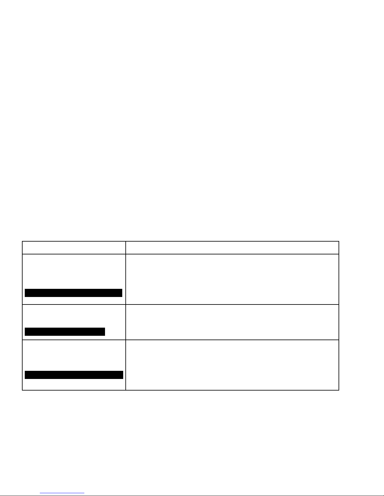
TABLE 4 - CYCLING SHUTDOWN MESSAGE
MESSAGE DESCRIPTION
VSD - DC Bus Voltage
Imbalance
BUS VOLTAGE IMBALANCE FAULT
VSD - High DC Bus Voltage
BUS OVER-VOLTAGE FAULT
VSD - High Internal Ambient
Temperature
HIGH AMBIENT TEMPERATURE FLT
The DC link is ltered by many large capacitors, which are rated for 450 VDC. These
capacitors are connected in series to achieve a 900 VDC capability for the DC link.
It is important that the voltage is shared equally between the 2 sets of series capaci-
tors. Each set of capacitors must share approximately ½ of the total DC link voltage.
If the difference in the voltage between the 2 sets of capacitors is greater than ± 88
VDC then this shutdown will occur.
The DC bus voltage is continuously monitored and a shutdown will occur if the DC
bus voltage exceeds 745 VDC (for 400 VAC & 460 VAC units) or 909 VDC (for 575
VAC units). This shutdown will protect the capacitors from a voltage that exceeds
their rating.
The ambient temperature of the OSCD is monitored by a temperature sensor
mounted on the OSCD logic board. The high ambient trip threshold is 145°F (63°C)
for all HP units except 424 HP which has a trip threshold of 153°F (67°C). If this
fault occurs, the fans and coolant pump will remain on until the internal ambient
temperature has fallen to 137°F (58°C) for all HP units except 424 HP which will
run the fans and coolant pump until the internal ambient has fallen to 145°F (63°C).
26
JOHNSON CONTROLS
Page 27
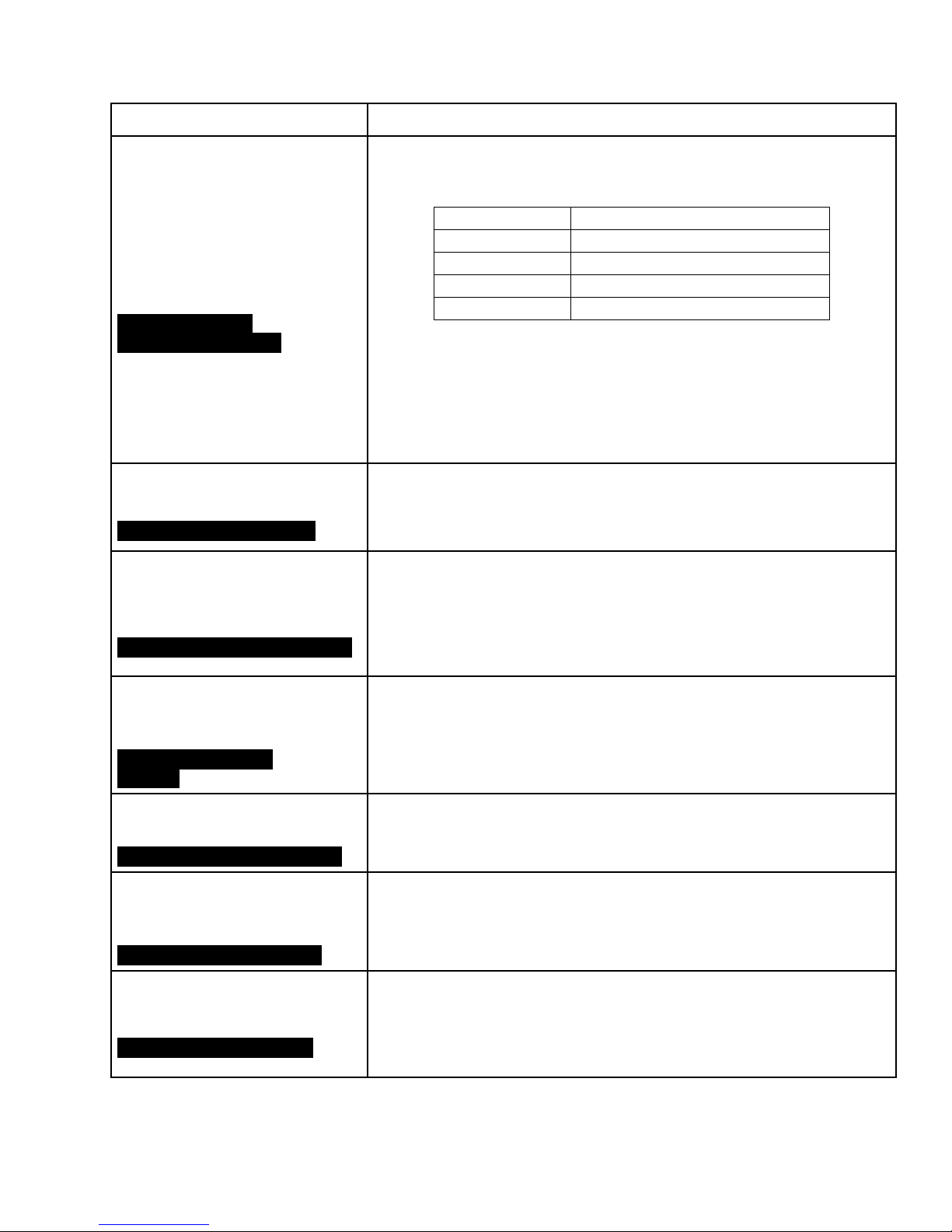
TABLE 4 - CYCLING SHUTDOWN MESSAGE (CONT'D)
MESSAGE DESCRIPTION
This shutdown is generated by the OSCD logic board. If any one phase of motor
current as measured by the Output Current Transformers exceeds a threshold.
Refer to the chart below for the shutdown threshold value.
DRIVE HP RATING THRESHOLD SHUTDOWN VALUE
270/292/351/424 771 AMPS PEAK
VSD - High Phase A (or B, C)
Instantaneous Current
PHASE A (OR B, C)
OVERCURRENT FAULT
If an Instantaneous Current Fault occurs but the chiller restarts and runs without a
problem, the cause may be attributed to a voltage sag on the utility power feeding
the OSCD that is in excess of the specied dip voltage rating for this product. This
is especially true if the chiller was running at, or near, full load. If there is a sudden
dip in line voltage, the current to the motor will increase. The chiller vanes cannot
close quickly enough to correct for this sudden increase in current and the chiller
will trip on this fault.
385/419/503/608 1200 AMPS PEAK
658/704 1890 AMPS PEAK
900 2750 AMPS PEAK
FORM 160.00-O4
ISSUE DATE: 12/19/2017
VSD - Initialization Failed
VSD INITIALIZATION FAILED
VSD - Invalid Current Scale
Selection
INVALID CURRENT SCALE FAULT
VSD - Logic Board Power
Supply
MAIN BOARD POWER
SUPPLY
VSD - Logic Board Processor
PWM COMMUNICATIONS FAULT
VSD - Low Converter
Heatsink Temperature
LOW CONV HEATSINK TEMP.
At power-up, the OSCD logic board will go through a process called initialization. At
this time, memory locations are cleared, jumper positions are checked, and communications links are established between the OSCD logic board, and the Control
Center.
The J1 connector on the OSCD logic board contains jumpers along with wires from
the output CTs. The jumpers congure the OSCD logic board to the HP rating of
the OSCD being used in this application in order to properly scale the output cur-
rent. If the jumper conguration is found by the logic board to be invalid, the system
will be shut down and the above message will be generated. The proper jumper
conguration is shown on the wiring label for the OSCD.
This shutdown is generated by the OSCD logic board, and it indicates that one of
the low voltage power supplies for the OSCD logic board has dropped below their
allowable operating limits. The power supplies for the logic boards are derived from
the secondary of the 120 to 24 VAC transformer which in turn is derived from the
480 to 120 VAC control transformer.
This shutdown is generated by the OSCD logic board. If a communications
problem occurs between the two microprocessors on the OSCD logic board this
shutdown will occur.
A thermistor sensor is located on the SCR/Diode block side of the copper chill plate
on the OSCD Power Unit. Anytime this thermistor detects a temperature of 37°F
(3°C) or lower a shutdown will occur.
VSD - Low DC Bus Voltage
LOW DC BUS VOLTAGE FLT
JOHNSON CONTROLS
If the line voltage were to quickly drop the current seen by the motor could exceed
it’s rating. The low bus voltage shutdown will prevent this from happening. The
shutdown is generated when the DC link voltage drops below 500 VDC for 460
VAC input voltage, 414 VDC for 380, 400, and 415 VAC input voltage or 600 VDC
for 575 VAC input voltage.
27
Page 28
FORM 160.00-O4
ISSUE DATE: 12/19/2017
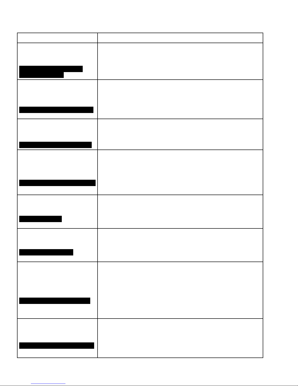
TABLE 4 - CYCLING SHUTDOWN MESSAGE (CONT'D)
MESSAGE DESCRIPTION
VSD - Low Inverter Baseplate
Temperature
LOW INVERTER BASEPLATE
TEMPERATURE FLT
A thermistor sensor is located inside the transistor module(s) on the OSCD power
unit. Anytime this thermistor detects a temperature of 37°F (3°C) or lower a shutdown will occur.
VSD - Phase A (or B, C) Gate
Driver
PHASE A (B, C) GATE DRIVER FLT
VSD - Precharge - DC Bus
Voltage Imbalance
PRECHARGE BUS V IMBALANCE
VSD - Precharge - Low DC
Bus Voltage
PRECHARGE LOW VOLTAGE FAULT
VSD - Run Signal
RUN RELAY FAULT
A second level of overcurrent current protection exists on the OSCD gate driver
board. The collector-to-emitter voltage of each transistor module is checked while
the device is turned on. This is called the collector-to-emitter saturation voltage. If
the voltage across the transistor module is greater than a set threshold, the transistor module is turned off. This fault can also be caused if the transistor is not being
turned on when it should.
The denition for this fault is identical to “ VSD - DC Bus Voltage Imbalance” except
that the fault has occurred during the precharge period, which begins during prelube. Refer to “ VSD - DC Bus Voltage Imbalance” shutdown for possible problems.
This fault has two different timing events. First, the DC Bus voltage must be equal
to or greater than 50 VDC for 460 VAC input voltage, 41 VDC for 380, 400 and
415 VAC input voltage, or 60 VDC for 575 VAC input voltage, 4 seconds after
pre-charge has begun. Second, the DC Bus voltage must be equal to or greater
than 500 VDC for 460 VAC input voltage, 414 VDC for 380, 400 and 415 VAC input
voltage or 600 VDC for 575 VAC input voltage, 20 seconds after pre-charge has
begun.
Two run signals are generated by the Control Center, one via hardware and the
second via the communications link. Upon receipt of either of the two run signals
by the OSCD logic board, a 5-second timer will begin. If the missing run signal is
not received within the 5-second window the OSCD logic board will shut down and
the Control Center will display the shutdown message.
VSD - Serial Communications
SERIAL RECEIVE FAULT
VSD - Single Phase Input
Power
SINGLE PHASE POWER SUPPLY
VSD - Stop Contacts Open
INVERTER INITIATED STOP FAULT
28
This message is generated when communications between the micro board and
the ACC board, or the ACC board and OSCD logic board is disrupted for a least 22
seconds. If the optional Harmonic Filter is installed then the fault can be generated
when the communications between the OSCD logic board and the Harmonic Filter
logic board, or the Harmonic Filter logic board and the ACC board is disrupted.
This shutdown is generated by the SCR Trigger board and relayed to the OSCD
logic board to initiate a system shutdown. The single phase control uses circuitry to
detect the loss of any one of the three input phases. The trigger board will detect
the loss of a phase within one half line cycle of the phase loss. An LED on the SCR
Trigger board will indicate that the board is detecting the fault, and not a wiring
problem between the trigger board and the OSCD logic board. This message is
also displayed every time power to the OSCD is restored, or if the input power
dips to a very low level. Usually it indicates that someone has opened the circuit
breaker.
Whenever the OSCD initiates a fault, it rst opens the fault relay on the OSCD
logic board. When the relay opens a message is sent to the ACC board, detailing
the cause of the fault. If this circuit ever opens without receiving an accompanying
cause for the fault over the communication link (within 11 communication tries, approximately 22 seconds) this message will be displayed. This fault may be replaced
with a Serial Communications fault if the serial link has failed.
JOHNSON CONTROLS
Page 29
TABLE 4 - CYCLING SHUTDOWN MESSAGE (CONT'D)
MESSAGE DESCRIPTION
The three phases of RMS lter current are measured by the output DCCTs’. This
information is sent to the harmonic lter logic board. If any one phase of lter cur-
Harmonic Filter - 110 % Input
Current Overload
FLTR OVERLOAD FLT
Harmonic Filter - DC Bus
Voltage Imbalance
FLTR BUS V IMBALANCE FLT
rent exceeds a threshold for 40 seconds a shutdown will occur. Refer to the chart
below for the shutdown threshold value.
DRIVE HP RATING THRESHOLD SHUTDOWN VALUE
270/292/351/424 128 AMPS RMS
385/419/503/608 176 AMPS RMS
658/704 277 AMPS RMS
The DC link is ltered by many large capacitors. These capacitors are connected
in series to achieve a higher DC link voltage then can be supported by a signal
capacitor. It is important that the voltage is shared equally between the two sets of
series capacitors. Each set of capacitors must share approximately 1/2 of the total
DC link voltage. The harmonic lter logic board then measures the voltage of the 2
sets of the bus capacitors. If at anytime while the harmonic lter is running that the
difference in the voltage between the 2 sets of capacitors is greater than 50 VDC
(for 380 through 460 VAC input voltage) 65 VDC (for 575 VAC input voltage), then
a shutdown will occur.
FORM 160.00-O4
ISSUE DATE: 12/19/2017
Harmonic Filter - DC Current
Transformer 1(or 2)
FILTER DCCT 1 (OR 2)
ERROR
Harmonic Filter - High DC
Bus Voltage
FLTR BUS OVER-VOLTAGE FLT
Harmonic Filter - High Phase
A (or B, C) Current
FLTR PHASE A (B, C)
OVERCURRENT
During initialization, with no current owing through the Direct Current Current
Transducers (DCCT’s), the DCCT’s output voltages are measured and compared
with a preset limit in the harmonic lter logic board. If the measured values exceed
the preset limits, the DCCT’s are presumed to be bad and this shutdown will be
generated.
The harmonic lter logic board continuously monitors the harmonic lter DC link
voltage if the level of the DC link voltage exceeds a range of 822 to 900 VDC (for
380 through 460 VAC input voltage) or 999 to 1099 VDC (for 575 VAC input volt-
age) this shutdown is initiated. Keep in mind that the harmonic lter has its own
DC Link as part of the harmonic lter power unit. The harmonic lter DC Link is not
connected in any way with the drive’s DC Link.
The output current of the harmonic lter is read by the Direct Current-Current
Transducer (DCCT). This current information is sent to the harmonic lter logic
board where it is compared against a threshold. If the output current of the har-
monic lter power unit is greater than the threshold, then the harmonic lter will turn
off for 5-6 line cycles. After that time the lter operation will resume. If the harmonic
lter operation is stopped 3 times within a period of 60 line cycles, then the lter
and VSD power units are shut down and this message is generated.
DRIVE HP RATING THRESHOLD SHUTDOWN VALUE
270/292/351/424 378 ± 59 AMPS Pk
385/419/503/608 523 ± 84 AMPS Pk
658/704 782 ± 118 AMPS Pk
Harmonic Filter
Communications
IEEE-519 FILTER FAULT
JOHNSON CONTROLS
This shutdown states that the hardware on the harmonic lter logic board is indicating a fault, but the software on the harmonic lter logic board does not state why.
The harmonic lter logic board signals a fault condition to the OSCD logic board
but does not respond to a software request for fault information.
29
Page 30
FORM 160.00-O4
ISSUE DATE: 12/19/2017
TABLE 4 - CYCLING SHUTDOWN MESSAGE (CONT'D)
MESSAGE DESCRIPTION
Harmonic Filter - Logic Board
Power Supply
FLTR POWER SUPPLY FLT
Harmonic Filter - Low DC Bus
Voltage
FLTR LOW BUS VOLTAGE FLT
Harmonic Filter - Phase
Locked Loop
FLTR PHASE LOCK LOOP FLT
This shutdown indicates that one of the low voltage power supplies on the harmon-
ic lter logic board have dropped below their permissible operating voltage range.
The harmonic lter logic board receives its power from the OSCD logic board. The
power supplies for the OSCD logic board are in turn derived from the secondary of
the 120 to 24 VAC transformer.
The harmonic lter dynamically generates its own lter DC link voltage by the interaction of the harmonic lter inductor and switching its transistors. This DC level is
actually higher than the level obtained by simply rectifying the input line voltage.
The DC link voltage is always higher on
the harmonic lter power unit then on the
OSCD VSD power unit.
Thus the harmonic lter actually performs a voltage “boost” function. This is necessary in order to permit current to ow into the AC line from the harmonic lter when
the AC line is at its peak level. This particular shutdown and its accompanying message are generated when the harmonic lter’s DC link voltage drops to a level less
than 80 VDC (for 380 through 460 VAC input voltage) and 110 VDC (for 575 VAC
input voltage) below the harmonic lter DC link voltage setpoint.
This shutdown indicates that a circuit called a “phase locked loop” on the harmonic
lter logic board has lost synchronization with the incoming power line for a period
of time.
Harmonic Filter - Precharge Low DC Bus Voltage
FLTR PCHARGE LOW BUS V FLT
Harmonic Filter - Run Signal
FLTR RUN RELAY FLT
Two minimum voltage thresholds must be met in order to complete the precharge
cycle. The rst occurs 1/10th of a second after pre-charge is initiated and the other
occurs 5 seconds after precharge is initiated. See table below for specic values.
NOMINAL INPUT
VOLTAGE VALUE
380-460 VAC 41 VDC 425 VDC
575 VAC 60 VDC 630 VDC
When a digital run command is received at the harmonic lter logic board from the
OSCD logic board, a 1/10 second timer is started. A redundant run command must
also occur on the communication link from the OSCD logic board before the timer
expires or the OSCD will be shut down.
1ST MINIMUM VOLT-
AGE VALUE
2ND MINIMUM
VOLTAGE VALUE
30
JOHNSON CONTROLS
Page 31
WARNING MESSAGES
General Information
A WARNING message will indicate that the operation
of the OptiSpeed Compressor Drive or the Harmonic
Filter is affected in some manner but the OptiSpeed
Compressor Drive is still functioning.
TABLE 5 - WARNING MESSAGES
WARNING DESCRIPTION
This message is displayed when the Pre-Rotation Vanes are not calibrated or
Warning - Vanes
Uncalibrated - Fixed Speed
have failed to calibrate, and the OptiSpeed Compressor Drive is enabled. Under
this condition the OSCD will run at a constant maximum speed. This message will
no longer appear after a successful calibration.
FORM 160.00-O4
ISSUE DATE: 12/19/2017
Warning - Harmonic Filter Data Loss
FILTER - DATA LOSS
Warning - Harmonic Filter Operation Inhibited
FILTER - OPERATION
INHIBITED
This message is displayed if the communications link between the OSCD logic,
and the harmonic lter logic, or the ACC boards are interrupted for at least a period of 20 seconds. This message can also occur as a background message when
the chiller is running. When this message is displayed all harmonic lter related
values are replaced with X’s. If communications is re-established, the message
will disappear, and normal values will again be displayed.
This message is displayed when the function of the Harmonic Filter is inhibited
at the Control Center. This message is no longer displayed when the function of
the Harmonic Filter is enabled at the Control Center. The function of the harmonic
lter can only be inhibited or turned on when the chiller is not running.
JOHNSON CONTROLS
31
Page 32

FORM 160.00-O4
ISSUE DATE: 12/19/2017
VSD FREQUENTLY ASKED QUESTIONS
Why doesn’t the measured input amps of the OSCD
agree with the rated FLA?
The input current to the OSCD may be considerably
lower, compared to the output current. This is due to
the power factor at the input to the OSCD being greater
than .95, and nearly unity when the Harmonic Filter
option is included. Chiller FLA must be measured at
the motor terminals, where the power factor is the normal motor power factor. Use a true RMS reading meter
to make these measurements.
Is a Condenser Water Strainer used with the shell
and tube heat exchanger?
Since the shell and tube heat exchanger can be cleaned
with a rifle brush, no extra precautions are needed to
keep the heat exchanger cleaned. No strainer is provided with this OSCD. The intent is to have the heat
exchanger cleaned annually. Gaskets are available (refer to the service parts list).
What is the timing of the Anti-Recycle when an
OSCD is applied?
The anti-recycle time is much quicker with an OSCD
than with a starter. The reason is the elimination of
inrush current on start-up. The OptiSpeed compressor drive slowly accelerates the compressor motor so
that the motor does not consume more than 100% of
the motor’s nameplate full load amps. The anti-recycle time is five (5) starts in succession, followed by a
ten minute wait. After ten minutes, the OSCD can be
started five more successive starts. This is permitted
on OSCD units only, due to the low current draw and
reduced motor heating during startup.
Should the customer install isolation between the
Power Conduits and the OptiSpeed Compressor
Drive?
We no longer require a section of non-metallic conduit
at the entrance and exit of the OSCD as we did on previous products. If any customer or installer wishes to
continue to follow this practice, we have no objections
as long as the OSCD is properly grounded.
When is a Booster Pump required on a Retrofit OptiSpeed Compressor Drive?
Detailed information is supplied in Form 160.05-N4. In
general, the OSCD requires 8 ft of head for proper water flow to the OSCD heat exchanger. If this amount of
head is not available, then a booster pump is required.
Can I apply an OptiSpeed Compressor Drive to a
generator?
Yes, the OSCD can be applied to a generator. No modifications are required for a generator application. We
have several OSCD installations running on generator
power without difficulty. It is necessary that the generator’s output voltage and frequency be maintained
within the specified range for that particular OSCD.
This is usually not a problem for most generators, since
motor current at startup is limited to less than 1X the
Full Load Amps (FLA).
My chiller will not slow down, why?
The OSCD will not reduce the motor speed until the
leaving chilled water temperature is below 0.5 degree
from setpoint. Once in this window, the speed still cannot be reduced until the operation is deemed to be stable, based upon the vanes are not continually moving
open and closed to maintain temperature. This hunting
effect is normally due to one of the following:
• Chilled water and Condenser water ows are not
at design GPMs. The rate of change in ow maybe
too fast for the chiller to be determined as stable.
• Return water temperature is varying due to 3-way
valves or other system conguration, and the
chiller is simply following changes in load.
• Vane stroke is too large. Remove the sensitivity
jumper in the Micro Computer Control Center, or
program a lower sensitivity on the OptiView Control Center. Also, check the vane motor to see that
the fullest possible stroke is being utilized. Moving the vane motor arm pivot point closer to center, and extending the degrees of travel by adjusting the internal end stops, will reduce the amount
of vane action for the same period of operation.
32
JOHNSON CONTROLS
Page 33

FORM 160.00-O4
ISSUE DATE: 12/19/2017
• Verify that the condenser is clean.
• Verify that the liquid level control is working
properly, and maintaining a refrigerant level in
the condenser.
• Ensure that the condenser water temperature is
proper for the load on the chiller. In many cases,
the condenser water temperature is still at 85°F.
Failure to reduce speed may also be due to the system
having been placed in Manual Speed when in VSD
Service Mode.
Do I have a problem with my coolant? The pink
color is no longer visible?
The coolant normally has a pink or rose color when
new. After several months of operation, this color may
dissipate, and the coolant may appear almost colorless.
The lack of the color in the coolant does not necessarily
indicate a problem. Most colorless samples test above
1000 PPM nitrite, which is normal. There is no need to
flush the system unless you find the coolant becoming
opaque or cloudy. In this case we suggest you obtain a
sample for analysis, then flush the system with coolant
and install fresh coolant. The coolant must be changed
every year regardless of color or test results. The coolant is required to be changed every year.
JOHNSON CONTROLS
33
Page 34

FORM 160.00-O4
ISSUE DATE: 12/19/2017
THIS PAGE INTENTIONALLY LEFT BLANK
34
JOHNSON CONTROLS
Page 35
ISSUE DATE: 12/19/2017
The following factors can be used to convert from
English to the most common SI Metric values.
TABLE 6 - SI METRIC CONVERSION
MEASUREMENT MULTIPLY ENGLISH UNIT BY FACTOR TO OBTAIN METRIC UNIT
Capacity Tons Refrigerant Effect (ton) 3.516 Kilowatts (kW)
Power Horsepower 0.7457 Kilowatts (kW)
Flow Rate Gallons / Minute (gpm) 0.0631 Liters / Second (l/s)
Feet (ft) 0.3048 Meters (m)
Length
Inches (in) 25.4 Millimeters (mm)
Weight Pounds (lbs) 0.4536 Kilograms (kg)
Velocity Feet / Second (fps) 0.3048 Meters / Second (m/s)
Feet of Water (ft) 2.989 Kilopascals (kPa)
Pressure Drop
Pounds / Square Inch (psi) 6.895 Kilopascals (kPa)
FORM 160.00-O4
TEMPERATURE
To convert degrees Fahrenheit (°F) to degrees Celsius
(°C), subtract 32° and multiply by 5/9 or 0.5556.
Example: (45.0°F - 32°) x 0.5556 = 7.22°C
To convert a temperature range (i.e., a range of 10°F)
from Fahrenheit to Celsius, multiply by 5/9 or 0.5556.
Example: 10.0°F range x 0.5556 = 5.6 °C range
JOHNSON CONTROLS
35
Page 36

5000 Renaissance Drive, New Freedom, Pennsylvania USA 17349 800-861-1001 Subject to change without notice. Printed in USA
Copyright © by Johnson Controls 2017 www.johnsoncontrols.com ALL RIGHTS RESERVED
Form 160.00-O4 (1217)
Issue Date: December 19, 2017
Supersedes: 160.00-O4 (415)
 Loading...