

Page 1
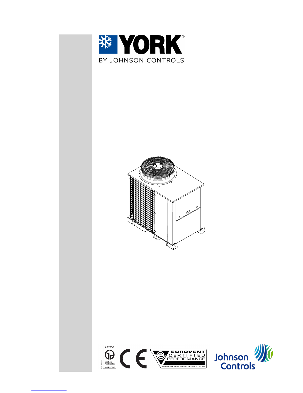
LARGE SPLIT AIR ‑ AIR VITALITY
SERIES Air Conditioners
Quick installation guide
Ref.: N-40341_EN 0112
Page 2
Index
1 Quick installation guide............................................................................................................1
1.1 Safety instructions....................................................................................................................2
1.2 Icons used in this document.....................................................................................................2
1.3 Instructions for storage, transport, loading and unloading of the unit......................................3
1.3.1 Hoisting points..........................................................................................................................3
1.3.2 Centre of gravity of the unit......................................................................................................4
1.3.3 Disposal of packaging..............................................................................................................4
1.4 Measurements, clearances and accesses...............................................................................5
1.4.1 Minimum clearance..................................................................................................................5
1.4.2 General dimensions, VIR 25A..................................................................................................6
1.4.3 General dimensions, VIR 40A..................................................................................................7
1.4.4 General dimensions, VIR 45A, VIR 60A...................................................................................8
1.4.5 General dimensions, VIR 75A, VIR 90A...................................................................................9
1.4.6 General dimensions and accesses (VAC-VAH 20A/25A/30A models)..................................10
1.4.7 General dimensions and accesses (VAC-VAH 40A/45A/60A models)..................................11
1.4.8 General dimensions and accesses (VAC-VAH 75A/90A models)..........................................12
1.5 Instructions for installation and connection of the unit...........................................................13
1.5.1 Characteristics of the location................................................................................................13
1.5.2 Characteristics of the facility where the unit will be installed..................................................13
1.5.3 Specifications for the foundation or anchoring of the unit......................................................14
1.5.4 Unit refrigerant connection.....................................................................................................14
1.5.5 Connection and preparation of the various connections........................................................18
1.6 Instructions for starting up the unit.........................................................................................22
1.6.1 Electrical checks.....................................................................................................................22
1.7 Unblocking the unit safely in case of breakdown...................................................................23
2 Unit installation data...............................................................................................................24
2.1 List of tests for unit start-up....................................................................................................25
2.2 Start-up data..........................................................................................................................26
Index
i
Page 3

1
Quick installation guide
Page 4
1.1 Safety instructions
This document contains the necessary information for the safe and efficient transportation, assembly
and installation of the air conditioning unit. This guarantees the condition of the unit and its operating
safety.
Only an authorised company may assemble the air conditioning unit.
A T T E N T I O N
Only authorised companies with the appropriate technical resources and suitably trained personnel may
install the air conditioning unit.
C A U T I O N
The specialists responsible for installing the air conditioning unit must make sure they have all of the
information and knowledge required to correctly install, test and deliver the unit. Johnson Controls Inc.
shall not be considered responsible for any damage caused by installation of the unit that is no consistent
with that described in this document or others specifically provided with the unit.
During regular equipment installation, the fitter must pay special attention to certain situations in order
to prevent injuries or damage to the unit.
Situations that could jeopardise the safety of the fitter or that of others nearby or that could put the unit
itself at risk are clearly indicated in this manual.
A series of special symbols are used to clearly identify these situations.
Pay careful attention to these symbols and to the messages following them, as your safety and the safety
of others depends on it.
1.2 Icons used in this document
D A N G E R
• The text following this symbol contains information and instructions relating directly to your safety
and physical wellbeing.
• Not taking these instructions into account could lead to serious, very serious or even fatal injuries to
you and others in the proximities of the unit.
Information can also be found on safe procedures during unit handling. This will help reduce the risk of
accidents.
C A U T I O N
• The text following this symbol contains information and instructions relating directly to your safety
and physical wellbeing.
• Not taking these instructions into account could lead to minor injuries to you and others in the
proximities of the unit.
• Not taking these instructions into account could lead to unit damage.
Information can also be found on safe procedures during unit handling. This will help reduce the risk of
accidents.
N O T E
• The text following this symbol contains information or instructions that may be of use or that is worthy
of a more thorough explanation.
• Instructions regarding inspections to be made on unit parts or systems may also be included.
1
Quick installation guide
1.1 Safety instructions
2
Page 5
1.3 Instructions for storage, transport, loading and unloading of
the unit
C A U T I O N
Outdoor units must be moved and stored vertically to prevent oil from leaking from the compressor.
Delivery inspection
The unit should be carefully inspected for visible damage or abnormalities as soon as it is received.
Any abnormalities or damage to the unit should be communicated to both the transportation and
insurance company in writing.
Storage instructions
The unit should be stored in a place suitable to the purpose (warehouse or similar), protected from the
weather, water, humidity and dust.
Cover the unit with a canvas of a suitable size.
The unit should be appropriately protected from knocks and dust, ensuring the protective parts it was
supplied with remain in place. Where these are not in place, establish the necessary protections and/or
barriers to keep vehicles or fork-lift trucks away.
Transport, loading and unloading of the unit
The units should only be handled by personnel from the company responsible for their installation.
Transport of the unit should be in such a manner that no damage is caused by faulty or inadequate
mooring to the bed or body of the vehicle.
Where necessary, protect all of the edges of the unit against knocks and scratches and moor it to the
bed or body of the vehicle using suitable textile belts or slings to keep it perfectly still.
Loading and unloading the unit from a truck or trailer should be on flat, solid ground using an appropriate
crane with sufficient capacity.
1.3.1 Hoisting points
The points designed for hoisting the unit are located on the beams on its base.
Before hoisting the unit, check that the cables or slings are firmly hooked to these points and make sure
the crane and the cables or slings are capable of lifting the weight.
Place spacers at the top of the unit to prevent the cables or slings from touching it.
Attach guide ropes so that the unit does not rotate freely.
The cables or slings should be long enough to form an angle of over 45º to the horizontal plane. Hoist
the unit keeping it in a horizontal position.
D A N G E R
There should not be onlookers within a radius of 10 m of the unit when it is being hoisted.
Quick installation guide
1
Instructions for storage, transport, loading and unloading of the unit 1.3
3
Page 6
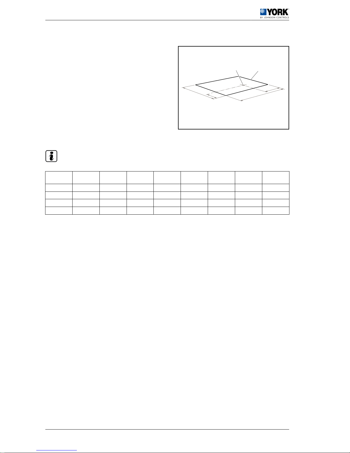
1.3.2 Centre of gravity of the unit
2. Centre of gravity.
3. End of the outdoor coil.
Centre of gravity values table
N O T E
All measurements in mm.
Models
VAC-
VAH 20A
VAC-
VAH 25A
VAC-
VAH 30A
VAC-
VAH 40A
VAC-
VAH 45A
VAC-
VAH 60A
VAC-
VAH 75A
VAC-
VAH 90A
A 441 441 441 813.5 813.5 813.5 813.5 813.5
B 500 500 500 510 510 510 785 785
C 1354 1354 1354 1453 1453 1453 2099 2099
D 882 882 882 1627 1627 1627 1627 1627
1.3.3 Disposal of packaging
The packaging is recyclable. Dispose of it in the appropriate place or take it to an appropriate collection
centre. Respect the regulations in force for this type of waste in the country where the unit is being
installed.
Packaging remains must be correctly disposed of. Improper disposal of packaging generates
environmental problems that affect human life.
A
B
C
D
1
2
1
Quick installation guide
1.3 Instructions for storage, transport, loading and unloading of the unit
4
Page 7
1.4 Measurements, clearances and accesses
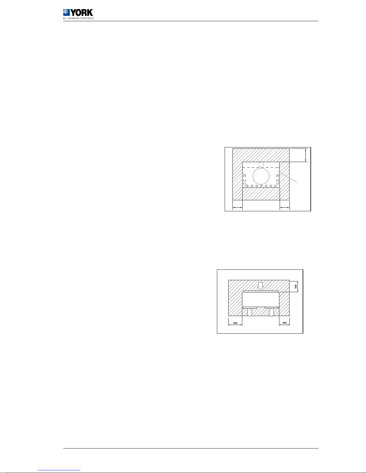
1.4.1 Minimum clearance
When installing each unit, clearances should be left for:
1. Intake and discharge of air from the outdoor unit.
2. Connection of drain and electricity pipes.
3. Air ducts.
4. Maintenance servicing.
5. Power supply connections.
VAC ‑ VAH unit
VIR unit
600
800
600
1
Quick installation guide
1
Measurements, clearances and accesses 1.4
5
Page 8
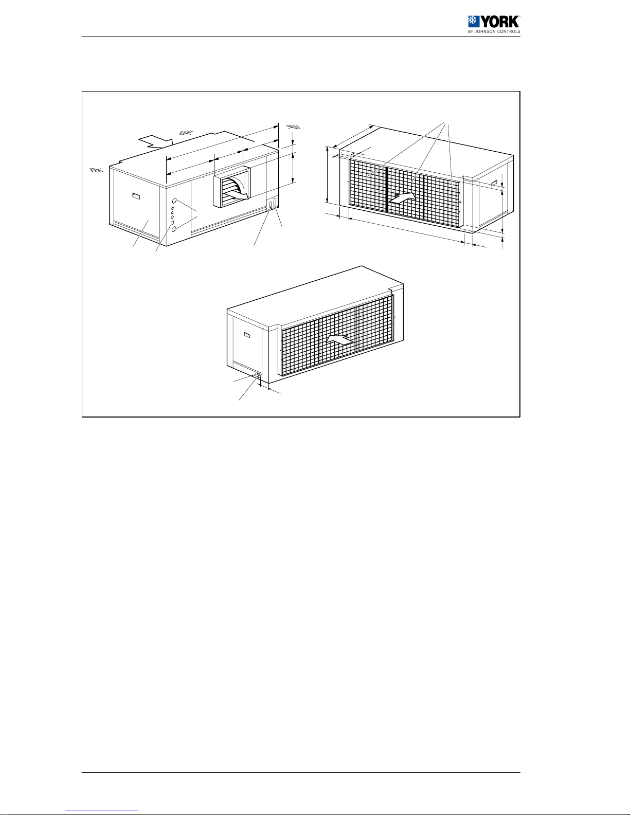
1.4.2 General dimensions, VIR 25A
1363
403
480
480
592
347
40
792
30
21
40
32
520
1094
140
129
B
A
A
5
4
1
2
3
6
164
30
7
A. Minimum clearance 600 mm
B. Minimum clearance 800 mm
1. Gas connection 1 ‑ 1/8”
2. Liquid connection 1/2”
3. Hot water coil accessory connections
4. Electrical connections
5. Motor access panel
6. Filters
7. Drain pipe (outer diameter 28,5 mm)
1 Quick installation guide
1.4 Measurements, clearances and accesses
6
Page 9
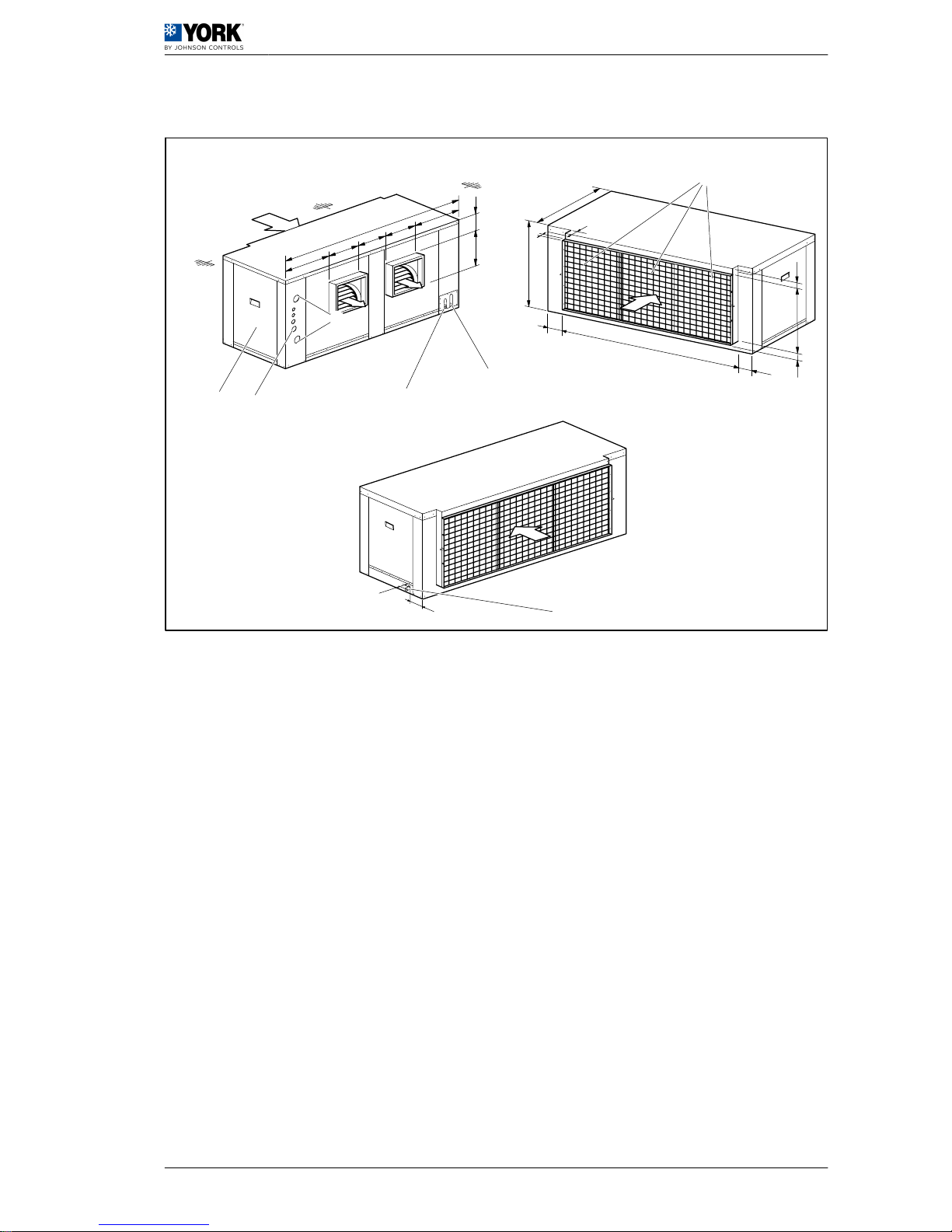
1.4.3 General dimensions, VIR 40A
30
164
7
B
A
A
347
79
1745
442
442
316
229
316
5
4
1
2
3
792
30
21
1337
196
212
665
593
40 32
6
A. Minimum clearance 600 mm
B. Minimum clearance 800 mm
1. Gas connection 1 ‑ 1/8”
2. Liquid connection 5/8”
3. Hot water coil accessory connections
4. Electrical connections
5. Motor access panel
6. Filters
7. Drain pipe (outer diameter 28,5 mm)
Quick installation guide 1
Measurements, clearances and accesses 1.4
7
Page 10
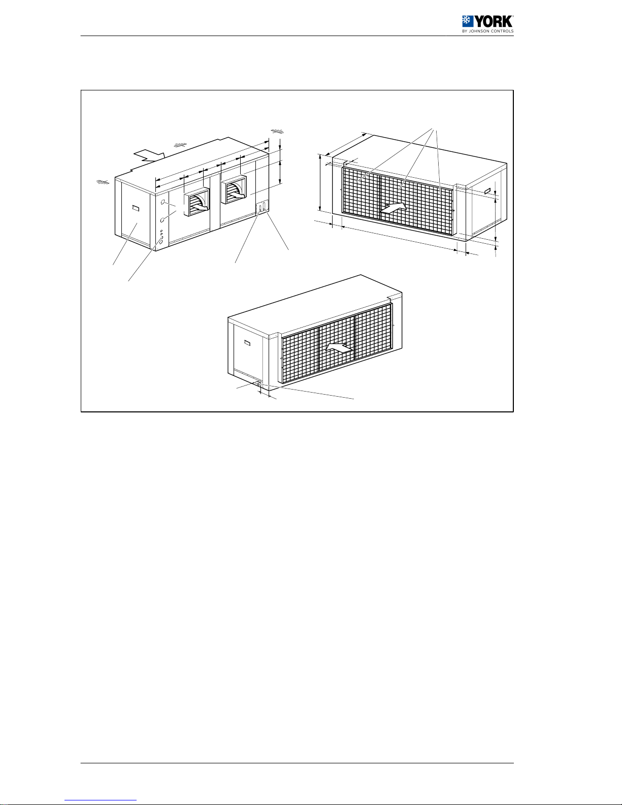
1.4.4 General dimensions, VIR 45A, VIR 60A
30
164
7
2245
567
567
401
309
401
347
79
5
4
1
2
B
A
A
3
6
779
30
21
1920
112
213
764
692
40 32
A. Minimum clearance 600 mm
B. Minimum clearance 800 mm
1. Gas connection 1 ‑ 1/8” (x2)
2. Liquid connection 1/2” (45A), 5/8” (60A) (x2)
3. Hot water coil accessory connections
4. Electrical connections
5. Motor access panel
6. Filters
7. Drain pipe (outer diameter 28,5 mm)
1 Quick installation guide
1.4 Measurements, clearances and accesses
8
Page 11
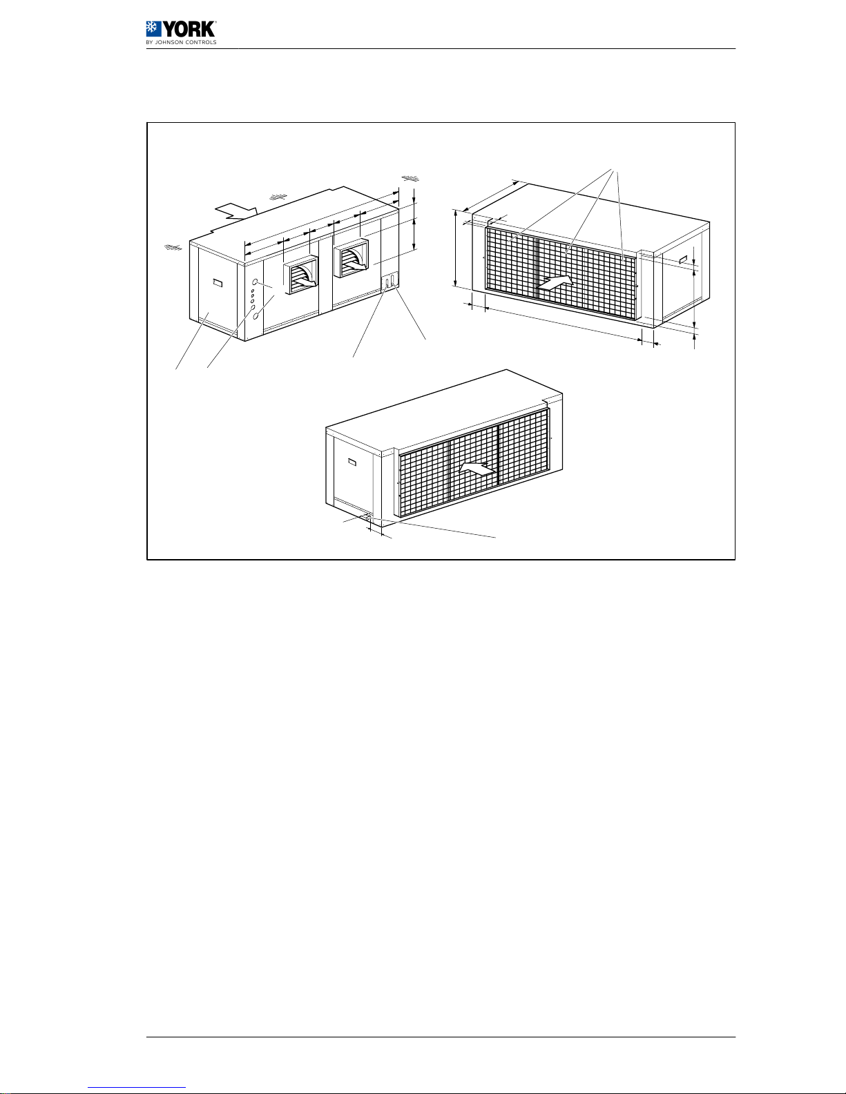
1.4.5 General dimensions, VIR 75A, VIR 90A
898
30
21
2196
202
260
838
766
40 32
2658
663
663
478
376
478
409
79
5
4
1
2
B
A
A
3
30
204
7
6
A. Minimum clearance 600 mm
B. Minimum clearance 800 mm
1. Gas connection 1 ‑ 3/8” (x2)
2. Liquid connection 7/8” (x2)
3. Hot water coil accessory connections
4. Electrical connections
5. Motor access panel
6. Filters
7. Drain pipe (outer diameter 28,5 mm)
Quick installation guide 1
Measurements, clearances and accesses 1.4
9
Page 12
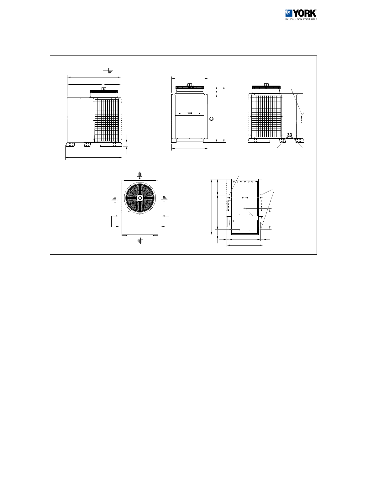
1.4.6 General dimensions and accesses (VAC-VAH 20A/25A/30A models)
1311
891
420
1354
877
200
1
600
600
600
1000
760
882
61
1000
882
A
B
61
1354
840
383
2
3
= =
3
3
D
132
95
C
500
1. Electrical connections B. Liquid pipe diameter
2. Centre of gravity VAC-VAH 20A/25A: 1/2”
3. Ø 14 support points VAC-VAH 30A: 5/8”
Weight per support point
C
.
VAC-VAH 20A: 1030
VAC-VAH 20A/25A: VAC-VAH 25A: 1030
VAC-VAH 30A: VAC-VAH 30A: 1182
A. Gas pipe diameter
D
.
VAC-VAH 20A: 1230
VAC-VAH 20A/25A: 1-1/8” VAC-VAH 25A: 1230
VAC-VAH 30A: 1-1/8” VAC-VAH 30A: 1382
1 Quick installation guide
1.4 Measurements, clearances and accesses
10
Page 13
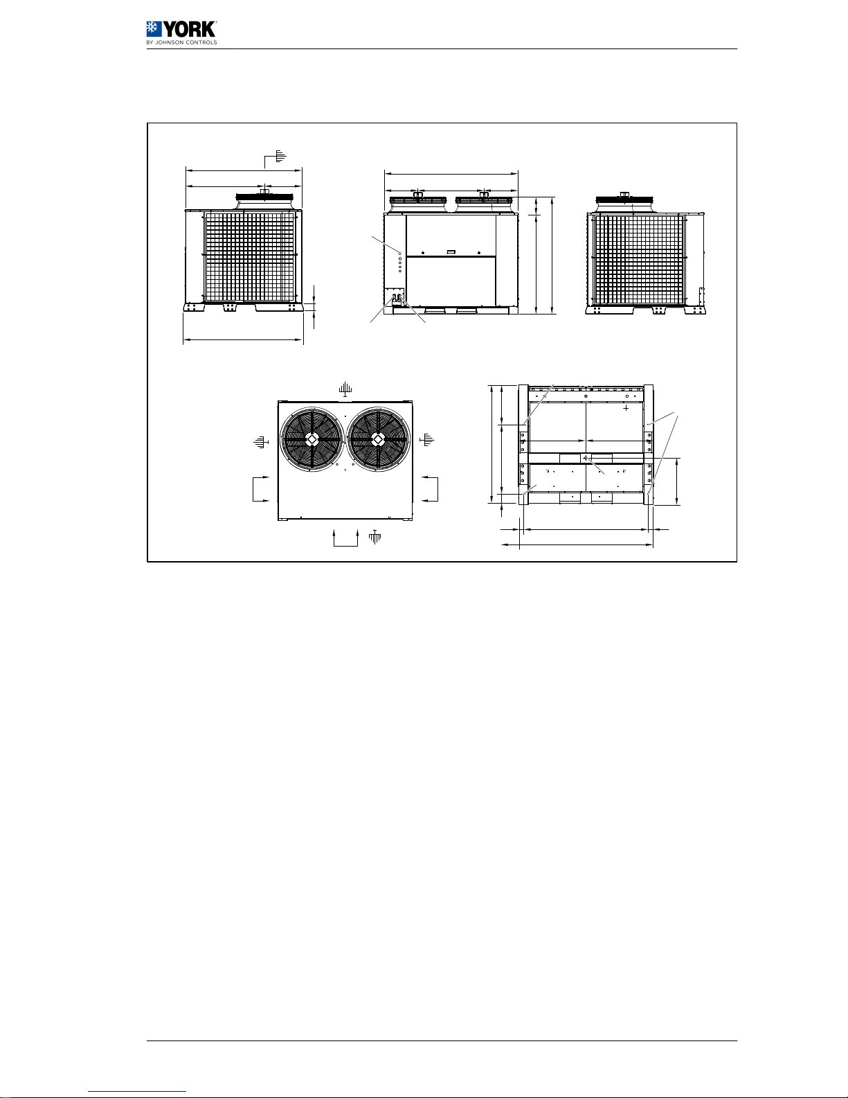
1.4.7 General dimensions and accesses (VAC-VAH 40A/45A/60A models)
1411
961
450
1453
95
800
414
413
1627
200
1
600
600
600
1000
1523
1627
52
52
1453
840
483
510
B
A
130
1000
D
C
2
3
= =
3
3
1. Electrical connections B. Liquid pipe diameter
2. Centre of gravity VAC-VAH 40A: 5/8”
3. Ø 14 support points VAC-VAH 45A: 2x 1/2”
Weight per support point VAC-VAH 60A: 2x 5/8”
VAC-VAH 40A: C. VAC 40A, 45A, 60A 1178
VAC-VAH 45A: VAH 40A 1178
VAC-VAH 60A: VAH 45A, 60A 1229
A. Gas pipe diameter D. VAC 40A, 45A, 60A 1378
VAC-VAH 40A: 1-1/8” VAH 40A 1378
VAC-VAH 45A: 2x 1-1/8” VAH 45A, 60A 1429
VAC-VAH 60A: 2x 1-1/8”
Quick installation guide 1
Measurements, clearances and accesses 1.4
11
Page 14
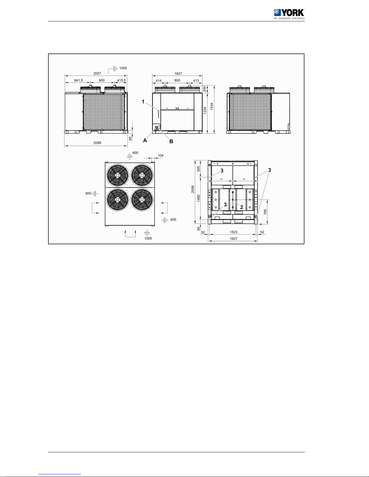
1.4.8 General dimensions and accesses (VAC-VAH 75A/90A models)
1. Electrical connections A. Gas pipe diameter
2. Centre of gravity VAC-VAH 75A/90A: 2x 1-3/8”
3. Ø 14 support points B. Liquid pipe diameter
Weight per support point VAC-VAH 75A/90A: 2x 7/8”
VAC-VAH 75A/90A:
1 Quick installation guide
1.4 Measurements, clearances and accesses
12
Page 15
1.5 Instructions for installation and connection of the unit
1.5.1 Characteristics of the location
Location of VIR 25A to 90A indoor units
Locate the indoor unit as close as possible to outdoor walls for easier installation, maintenance and
drainage. Make sure the ceiling fastening where the unit is located will withstand its weight.
The unit must be installed completely horizontally or sloping slightly towards the drain side.
Location of VAC/VAH 20A to 90A outdoor units
The location of the unit must be studied to ensure a completely satisfactory installation. To do so, the
environmental conditions of the area where the unit is to be installed must be taken into account.
Furthermore, the normal weather conditions should be instrumental in determining the best position of
the unit and the hoods, screens or covers required to ensure its correct working order.
If possible, in warm zones like the southern Europe, the unit should be located on the north or east side
of the building or property.
The location chosen for the unit must provide the condenser with an unlimited air supply.
As well as the technical data given in this document and any others that are applicable, please bear in
mind that the unit has been designed for outdoors installation only.
Where the unit is to be installed at ground level, refer to section
Specifications for the foundation or
anchoring of the unit, see on page 14
.
Where the unit is to be installed on the roof of a building or property, make sure that the roof structure
can support the weight of the unit plus that of any optional equipment and/or accessories to be fitted.
Special instructions for locations where there is regular snowfall or with ambient temperatures of close
to 0ºC or less
In areas where there is regular or sporadic snowfall, the unit must be elevated above the ground or roof
where it is installed. The height should be enough to prevent the unit, the condenser and evaporator air
inlets and the access to the unit panels from becoming blocked by accumulated snow.
Protection against ice
In areas where the temperature can drop below 0ºC, there must be some kind of additional protection to
prevent the water in the condensate drain pipe from freezing.
Use a wire heating element in the drain trap as well as in the drain, where applicable.
In heat pumps, also use cord resistors in the outdoor coil tray to prevent any ice from accumulating.
Special instruction for locations with high ambient temperatures
In areas where the ambient temperature is over 43ºC, the unit must not be located in direct sunlight and,
therefore a specific sunshade will be required.
The installation of a special sunshade over the unit must not affect the air flow required by the unit to
work correctly. See
Minimum clearance, see on page 5
.
1.5.2 Characteristics of the facility where the unit will be installed
Indoor unit air ducts
The air duct installation where the unit is to be installed must be formed by a closed return duct system.
The additional installation of economisers or outdoor air intakes is not excluded.
To reduce operating noise, the supply and return air duct connections on the unit must be made using
flexible joints.
The supply and return air duct systems must be designed for the air flow requirements of the installation.
The ducts should not be sized based on the supply and return air connection sizes of the unit.
Quick installation guide
1
Instructions for installation and connection of the unit 1.5
13
Page 16
Hatches should be installed on each discharge duct bypass and where access is planned for cleaning
and replacement of filters.
1.5.3 Specifications for the foundation or anchoring of the unit
Where the unit is to be installed at ground level, the characteristics of the ground it will sit on must be
taken into account.
Characteristics, such as acceptable surface firmness, must be suitable for the foundation the unit
requires.
1.5.4 Unit refrigerant connection
The indoor and outdoor units are connected by coolant pipes that form a sealed coolant circuit.
Pipes to be used
C A U T I O N
Do not leave compressors or dehydrator filters exposed.
Use K or L-type cooling quality copper pipes, S/ASTMB88.
The pipes must be sealed and insulated until they are connected to the units.
The pipe insulation must be made of a suitable material with a minimum thickness of 8 mm to avoid
condensation and minimum temperature loss due to radiation.
Connection pipe installation
D A N G E R
Do not carry out work outdoors in the event of adverse weather conditions
C A U T I O N
Do not use stripping products on Cu ‑ Cu joints.
Use rods with a low melting point and a minimum silver content of 5% when welding the pipes. During
this process, there must be a current of dry nitrogen inside the pipe to prevent rust and scale from forming
that would damage the welding and, therefore, affect the watertightness of the circuit.
N O T E
• The connection pipes between units must be as short as possible.
• No drain traps are necessary where connecting piping specifications are met.
1
Quick installation guide
1.5 Instructions for installation and connection of the unit
14
Page 17
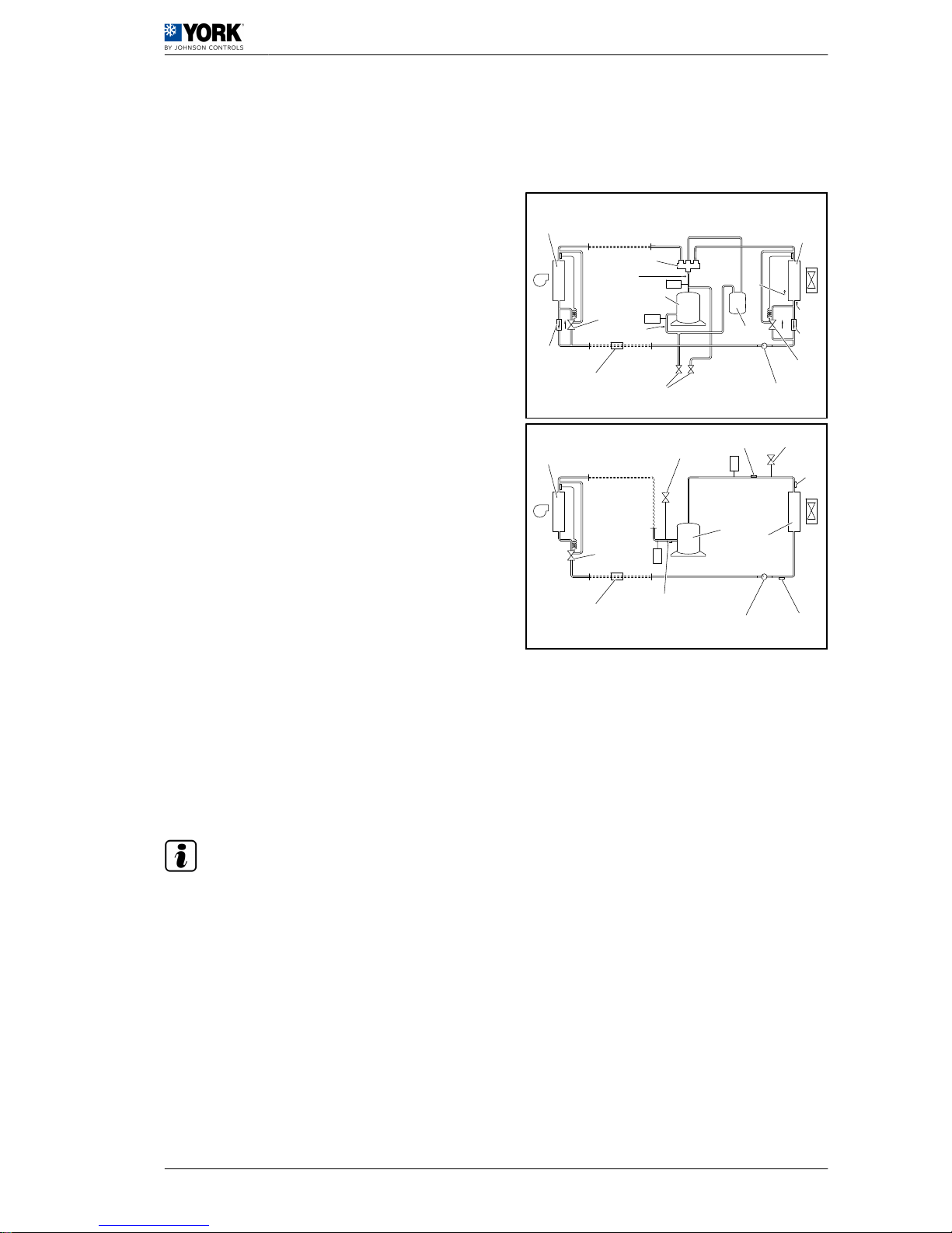
Cooling layout
The coolant pipes must be connected to the units using pipe flaring.
As indicated in the diagram, a dehydrator filter must be fitted (one or two, depending on model) on the
liquid pipe of the installation.
1. Indoor coil
2. Check valve
3. Expansion valve
4. Service valve
5. Suction accumulator
6. Liquid sight glass
7. Expansion valve
8. Check valve
9. Liquid probe
10.Outdoor air probe
11.Outdoor coil
12.4-way reversing valve.
13.Discharge probe
14.Compressor
15.Suction probe
16.Dehydrator filter (obligatory in the installation)
Vacuum and dehydrating
The presence of air and dampness in the cooling circuit must be completely eliminated to avoid:
• Damage to the compressor and other parts of the cooling circuit.
• A drop in unit performance.
• Capillary blocking due to freezing.
• Unwanted high pressure increases.
• Increased electricity consumption.
N O T E
Prior to the vacuum process, nitrogen gas can be swept through the system to remove most of the
dampness and other contaminants in the cooling circuit. The vacuum should be broken on several
occasions using nitrogen to ensure dampness is eliminated.
The vacuum is ensure in each cooling circuit as follows:
LP
HP
1
2
3
4
5
6
7
8
9
10
11
12
13
14
15
16
VAH
LP
HP
1
3
6
9
11
10
4
13
14
15
16
VAC
4
Quick installation guide
1
Instructions for installation and connection of the unit 1.5
15
Page 18
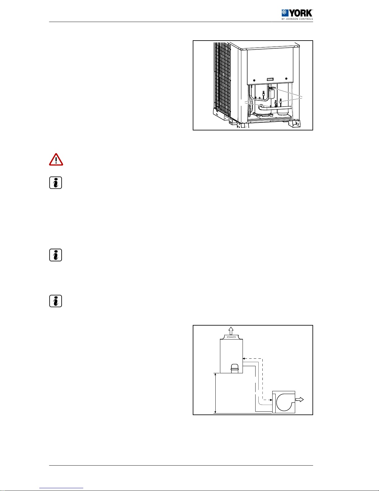
1. Connect the vacuum pump to the service valves
-1- on the installation and connect the service
manometers to the valve stems (¼” valves) -2- in
the circuit.
2. Open the stopcocks on the service valves and the
vacuum pump.
3. Activate the vacuum pump.
4. Vacuum to at least 50 microns.
5. Detect leaks.
Coolant charge
D A N G E R
Due to its characteristics, R-410A coolant must only be handled by qualified personnel.
N O T E
The unit is not supplied charged
The refrigerant charge is calculated for a 7,5 m length of piping. In installations with longer (or shorter)
lengths, add (reduce) coolant as indicated in the table below.
In installations with connection piping in excess of 25 m in length, 30 g of oil must be added for every
additional metre.
Follow the instructions below to add or charge coolant to the cooling pipes:
N O T E
The coolant charge must be weight-controlled using scales. The coolant must be charged in liquid phase
to ensure the components forming it are inserted in the correct proportions.
1. Connect the coolant cylinder to the low pressure or gas intake.
2. Open the stopcocks and allow the coolant to enter the pipes.
N O T E
Once the coolant has been correctly charged, the subcooling temperature (at the expansion valve inlet)
must be approximately 1 ºC and the overheating temperature between 5 and 10 ºC.
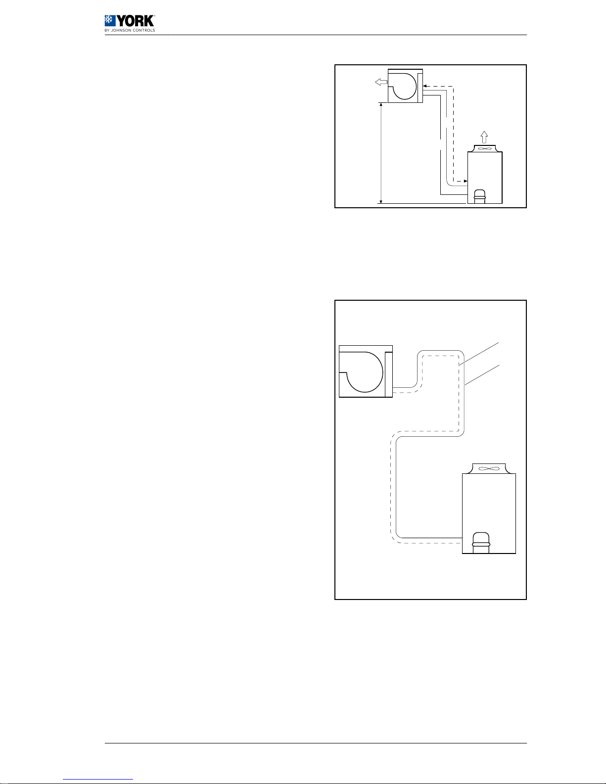
A Liquid cooling line.
B Gas cooling line.
H Vertical distance between units (max. 30 m).
L
Total pipe length (vertical + horizontal sec‐
tions). Laid and in one direction.
1 Outdoor unit.
2 Indoor unit.
1
2
H
A
B
L
1
2
1 Quick installation guide
1.5 Instructions for installation and connection of the unit
16
Page 19
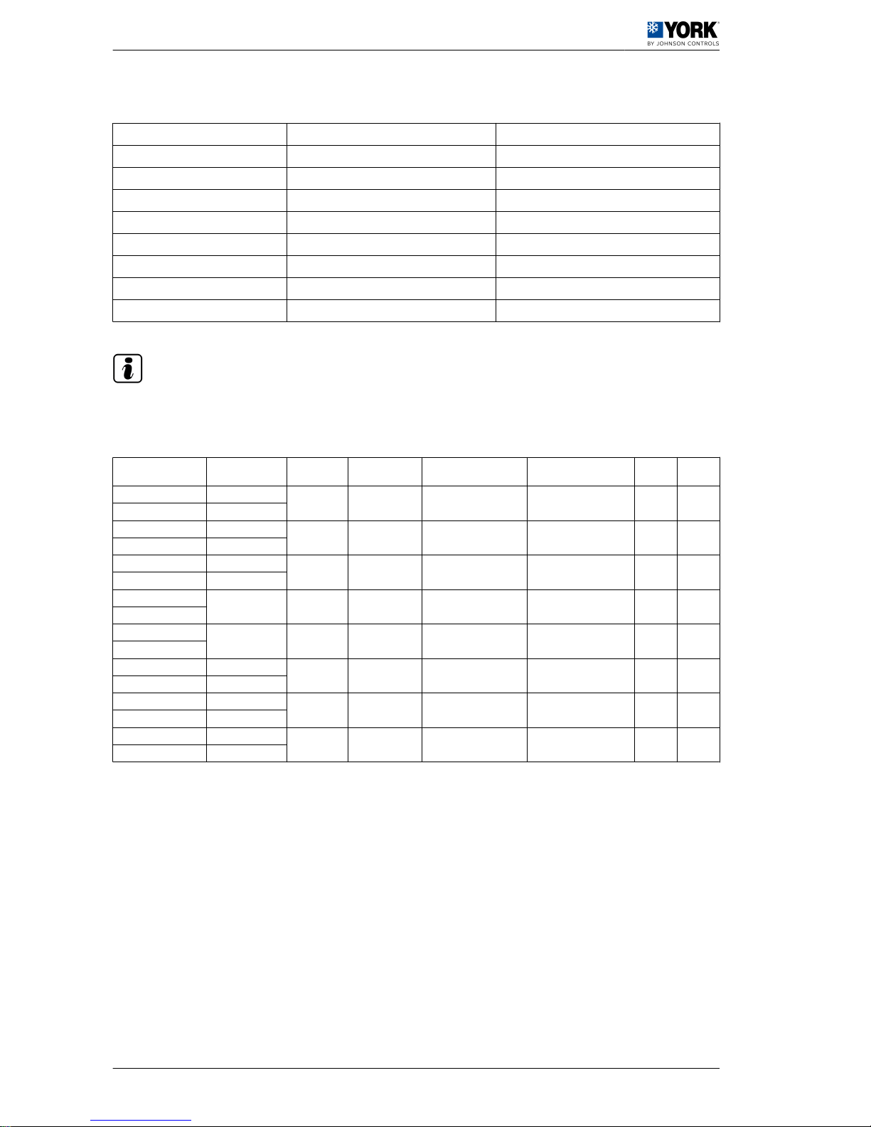
A Liquid cooling line.
B Gas cooling line.
H Vertical distance between units (max. 30 m).
L
Total pipe length (vertical + horizontal sec‐
tions). Laid and in one direction.
1 Outdoor unit.
2 Indoor unit.
Maximum length L: this is the sum of the lengths of all straight horizontal and vertical sections in one
direction, whether they hold liquid or gas.
Maximum equivalent length LE: this is the sum of the lengths of all straight horizontal and vertical sections
in one direction, whether they hold liquid or gas, plus the equivalent length of the accessories, basically
elbow joints and bends.
CALCULATION EXAMPLE
1 Outdoor unit.
2 Indoor unit.
3 ½” liquid pipe.
4 1 ⅛” gas pipe.
A, B, C, D Elbow joints (4)
E Bends (2)
L = 2 + 3 +3 + 6 + 4 + 7 + 6 = 31
31 < 50 is therefore correct
To calculate the equivalent length of the
interconnection piping and as for the charge loss
calculation, use the data of one of the liquid lines, i.e.
½” outer diameter. As can be seen in the diagram,
there are four elbow joints with an equivalent length
of 0,5 m according to the table and two 0,4 m bends
according to the table, to check that the equivalent
length of piping does not exceed the accepted
maximum:
LE = 2 + 3 + 3 + 6 + 4 + 7 + 6 + 4·(0,5) + 2·(0,4) = 33,8 m
33,8 < 60 is therefore correct.
A
B
H
L
1
2
1
2
2 m
3 m
3 m
6 m
4 m
7 m
6 m
A
B C
D
E
F
3
4
Quick installation guide
1
Instructions for installation and connection of the unit 1.5
17
Page 20
EQUIVALENT LENGTH ACCESSORIES IN METRES
Outer pipe diameter Short elbow joint radius 90º bend (Long radius)
3/8" 0,30 0,20
1/2" 0,40 0,30
5/8" 0,50 0,40
3/4" 0,50 0,40
7/8" 0,60 0,50
1 ⅛" 0,70 0,60
1 ⅜" 1,00 0,70
1 ⅝" 1,20 0,80
N O T E
The 45º elbow joints and bends (used in drain traps, for example) have half the equivalent length of the
90º bends.
Coolant charge according to piping diameter
Model
Rated R-410A
charge (kg)
No. of cir‐
cuits
Gas line diame‐
ter
Liquid line diameter Additional charge (g./m) L (m) LE (m)
VAC 20A / VIR 25A 12
1
1 - 1/8"
(28,5 mm)
1/2" (12,7 mm) 112 50
1
60
VAH 20A / VIR 25A 12
VAC 25A / VIR 25A 12,5
1
1 - 1/8"
(28,5 mm)
1/2" (12,7 mm) 112 50
1
60
VAH 25A / VIR 25A 12,5
VAC 30A / VIR 40A 12,5
1
1 - 1/8"
(28,5 mm)
5/8" (15,87 mm) 170 50 60
VAH 30A / VIR 40A 12,5
VAC 40A / VIR 40A
13,5 1
1 - 1/8"
(28,5 mm)
5/8" (15,87 mm) 170 50 60
VAH 40A / VIR 40A
VAC 45A / VIR 45A
11x2 2
1 - 1/8"
(28,5 mm)
1/2" (12,7 mm) 112 50 60
VAH 45A / VIR 45A
VAC 60A / VIR 60A 12,5x2
2
1 - 1/8"
(28,5 mm)
5/8" (15,87 mm) 170 50 60
VAH 60A / VIR 60A 12x2
VAC 75A / VIR 75A 15,5x2
2 1 ‑ 3/8" (35 mm) 7/8" (22 mm) 333 50 60
VAH 75A / VIR 75A 15,5x2
VAC 90A / VIR 90A 15x2
2 1 ‑ 3/8" (35 mm) 7/8" (22 mm) 333 50 60
VAH 90A / VIR 90A 15x2
L: maximum length on straight connection pipe sections.
LE: maximum equivalent length of unit connection pipes.
1
: As of a total sum of 20 metres in length on straight connection pipe sections (horizontal and vertical) between units, a suction accumulator of at
least 7 litres must be fitted on the gas line.
1.5.5 Connection and preparation of the various connections
Electricity. Power and control
POWER LINE
Power must be supplied to the unit through a specific power supply line with an exclusive power control
and differential breaker, installed in line with national and local regulations.
1
Quick installation guide
1.5 Instructions for installation and connection of the unit
18
Page 21
N O T E
For further information on this subject, always keep the current regulations for the country where the unit
is being installed at hand.
Make sure that the electricity supply line has enough capacity to power the unit. Its length, the cable
diameter and their protection (cover or jacket) should be appropriate for the unit.
Use a multimeter to check that the supply voltage
remains within the accepted limits.
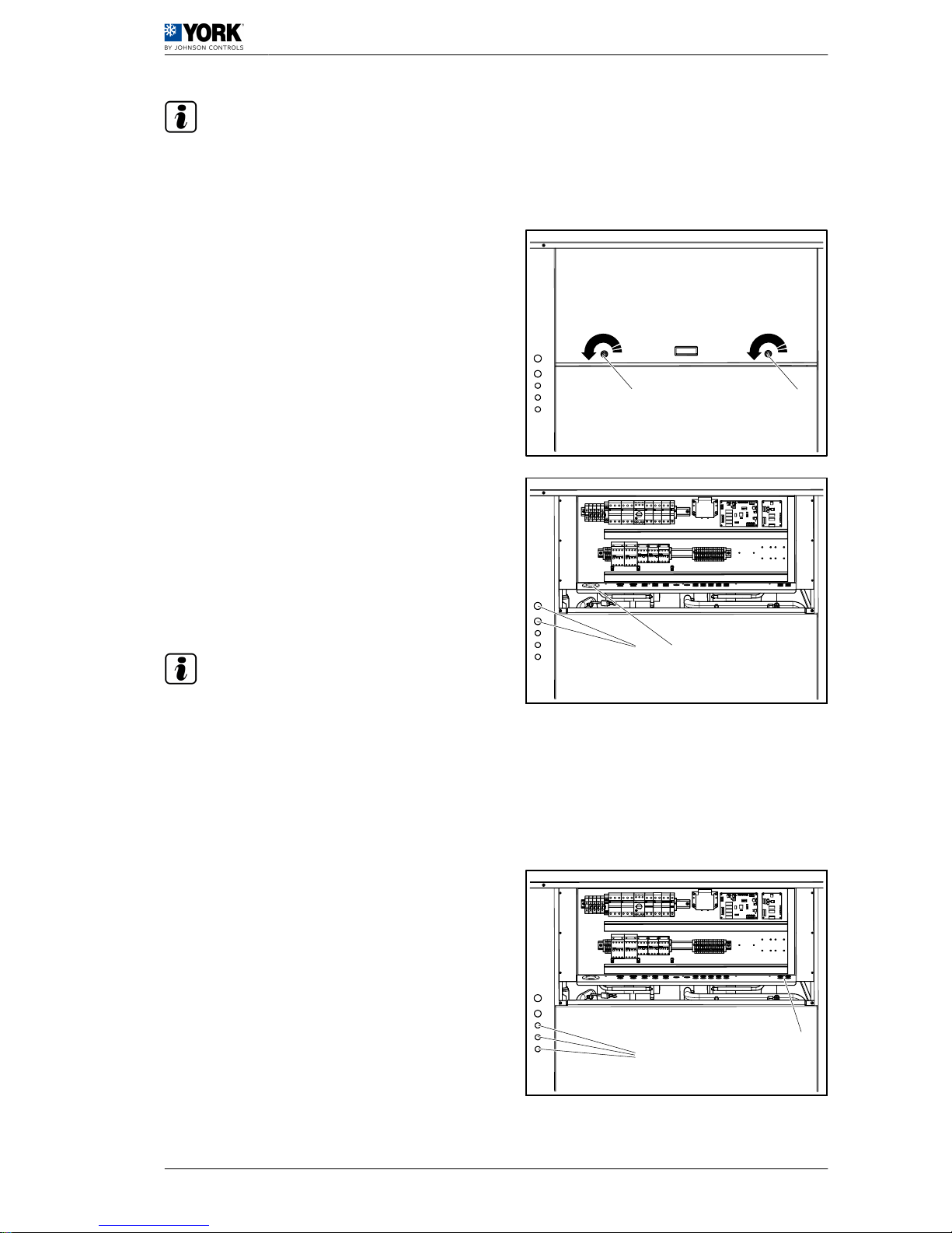
To install the power cable, loosen the closures -1- by
1/4 turn and remove the electrical board panel.
Press the appropriate openings on the edge of the unit
-1- until they are released.
Fit packing glands to fit the cable and pull the cable
through to the inside of the electrical panel through
the grommets in the tray -2-.
Connect the cable to the input connections indicated
and firmly tighten the securing bolts. Also consult the
Wiring Diagrams.
N O T E
The complete wiring diagram for the unit is attached
to the inside of the electrical panel.
The electrical panel is fitted with a phase detector to ensure the electrical connection follows the
sequence of phases R-S-T. Where the connection does not respect this sequence, the electronic control
circuit remains disconnected and the unit will not start.
To correct the phase sequence, change the position of two of the three unit power cables on the input
terminals.
CONTROL LINE
Passing the power and control cables through the
front of the unit.
Press the appropriate openings on the edge of the unit
-1- until they are released.
Fit packing glands to fit the cable and pull the cable
through to the inside of the electrical panel through
the grommets in the tray -2-.
Connect the cable to the terminals indicated and
firmly tighten the securing bolts. Also consult the
wiring diagrams for the unit and
Wiring diagrams, see
on page 21
.
1
1
2
1
2
1
Quick installation guide
1
Instructions for installation and connection of the unit 1.5
19
Page 22
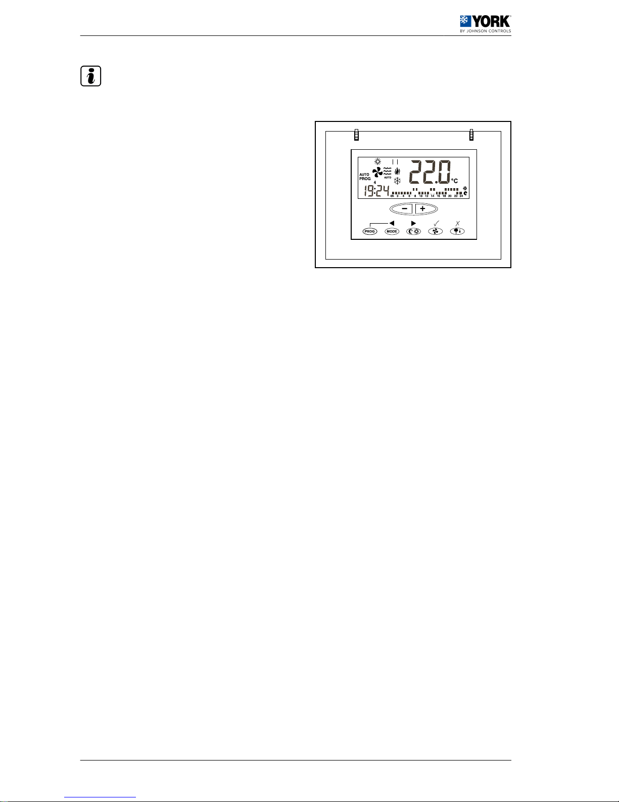
N O T E
The complete wiring diagram for the unit is attached to the inside of the electrical panel.
THERMOSTAT CONNECTION
The outdoor unit and the thermostat are connected by
means of a 10-pin x 0,22 mm2 shielded
communication cable. Connect the cable to the
terminals indicated and firmly tighten the securing
bolts. Also consult the wiring diagrams for the unit and
Wiring diagrams, see on page 21
.
1
Quick installation guide
1.5 Instructions for installation and connection of the unit
20
Page 23
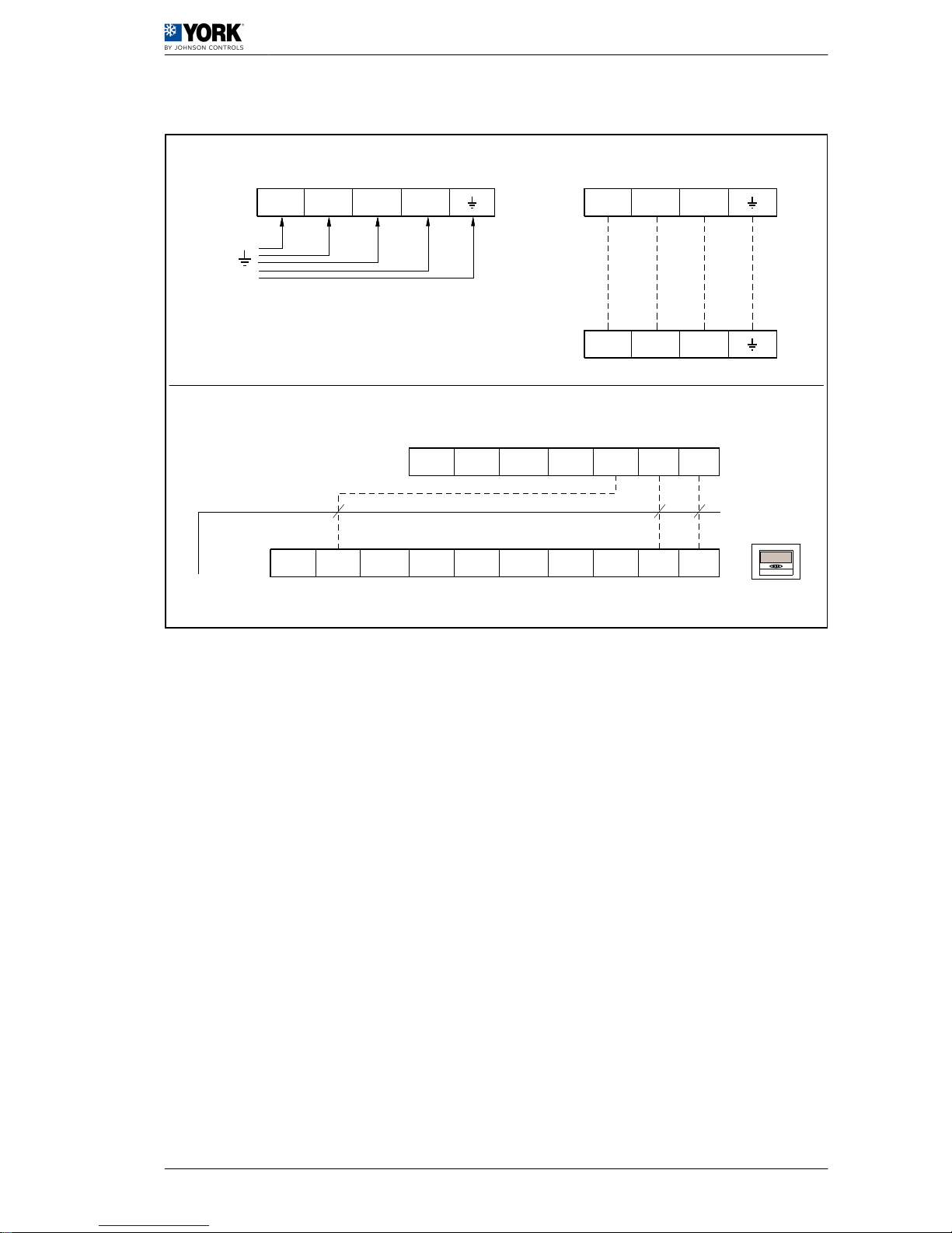
Wiring diagrams
G
Y2
O/B
Y1 G X1 B R
W
O/B
Y1X1 B RX2 Y2AL
G
F
E
1
2
L1 L2 L3
N 2 4 6
U1 V1 W1
D
C
B
A
1. Power connection
2. Thermostat connection
A. Main power supply
B. Outdoor unit
C. Contactor
D. Indoor fan motor (star connection)
E. Outdoor unit terminal strip
F. DPC-1 thermostat
G. 10-pin shielded communications cable x 0,22 mm
2
Condensates. Insulation and/or protection of ducts
Condensates should be released by means of a specific installation in line with local or national
regulations.
Quick installation guide
1
Instructions for installation and connection of the unit 1.5
21
Page 24
N O T E
For further information on this subject, always keep the current regulations for the country where the unit
is being installed at hand.
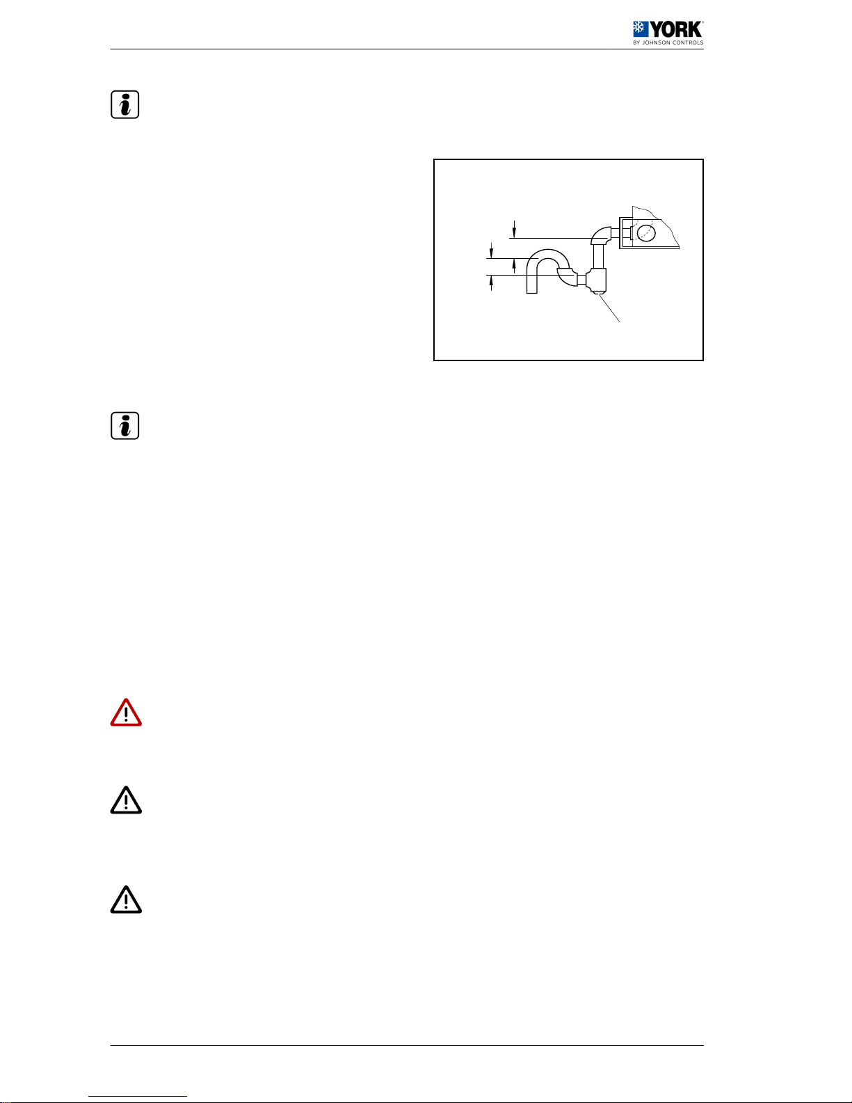
Install a drain trap on the exhaust outlet of the unit.
The drain trap must have an access register -1- to
facilitate emptying and cleaning when necessary.
Lay the condensate drain pipe from the connection at the bottom of the unit to a nearby drain.
N O T E
• The condensate drain pipe should be at a minimum gradient of 2% (2 cm of drop for each metre in
length).
• The condensate drain pipe must be correctly insulated.
Protection against ice
In areas where the temperature can be 0ºC or less, there should be some kind of additional protection
to prevent the water contained in the condensate drain pipe from freezing.
An heating element (wire heater) should be installed in the drain trap and in the condensate drain pipe.
For units with heat pumps, heating elements must also be installed in the outdoor coil tray to prevent
possible ice accumulation.
1.6 Instructions for starting up the unit
1.6.1 Electrical checks
D A N G E R
• All side panels except for that of the electrical box, must be fitted, closed and secured with their
corresponding locks before turning the general switch on the unit.
• The unit has a remote control, which means that the fan turbine may start unexpectedly.
C A U T I O N
Loose connection terminals produce overheating of cables and terminals. The unit will work incorrectly
and there is a risk of fire.
Check that the cables are firmly secured to their connection terminals.
C A U T I O N
Do not start the unit until all installation work has been completed.
Initial connection of the unit
Once all of the planned accessories are installed, and before starting the unit, its general switch on the
installation must be turned on.
50 mm
75 mm
1
1
Quick installation guide
1.6 Instructions for starting up the unit
22
Page 25
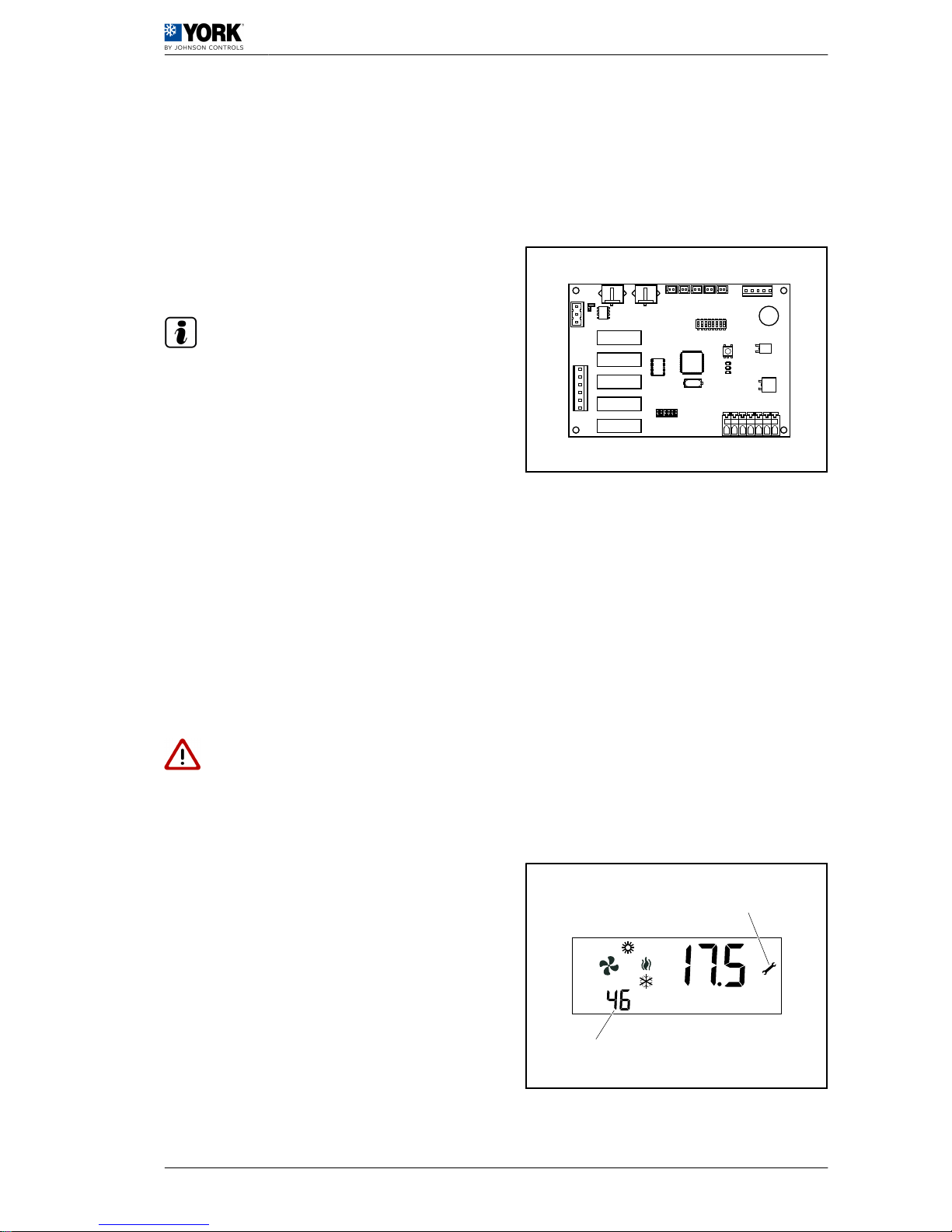
Press the "Test" button for two seconds so that the unit recognises the installed accessories. When the
recognition process is complete, the red pilot light switches off.
YKN2 Open control board
The unit control software is in the YKN2 Open control board. The control algorithm can be configured or
changed by:
• The position of the micro-switches.
• The connection of accessories detected by the board.
The control board indicates the faults detected by
means of the red V3 LED on the board or the fault
codes indicated on the DPC-1 thermostat.
N O T E
For further information, see the technical information
on the YKN2 Open control board.
Rotational direction of Scroll compressors
The Scroll compressors and the fans only operate correctly if they rotate in the correct direction. All of
the motors and compressors in the unit are connected so that they rotate correctly.
If the compressors are not connected correctly and are rotating in the wrong direction:
• The compressor will not compress.
• Operating noise will be abnormal.
• Electricity consumption (A) will be low.
• They overheat.
1.7 Unblocking the unit safely in case of breakdown
D A N G E R
• All side panels except for that of the electrical box, must be fitted, closed and secured with their
corresponding locks before turning the general switch on the unit.
• The unit has a remote control, which means that the fan turbine may start unexpectedly.
To unlock the unit, see "Restarting the HVAC unit in case of fault" in the User Manual.
If the thermostat display keeps showing the pilot light
-1- and any fault code -2- or if the air conditioning unit
does not start, contact a Johnson Controls Inc.
Authorised Technical Assistance Service.
Y2 O/B Y1 G X1 B R
AUTO
AUTO
ºC
1
2
Quick installation guide
1
Unblocking the unit safely in case of breakdown 1.7
23
Page 26

2
Unit installation data
Page 27
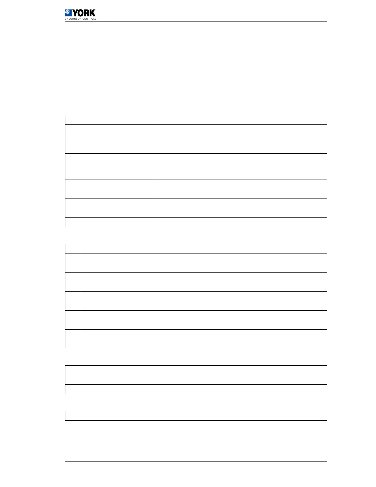
Please complete the following data to register the full details of the installation and the start-up inspection.
Complete the blank fields or mark the appropriate box, as applicable.
2.1 List of tests for unit start-up
Please complete the following forms to register the full details of the installation and the start-up
inspection.
Complete the blank fields or mark the appropriate box, as applicable.
Company performing installation:
Company performing installation:
Installing technician:
Name / project number:
Location of the unit:
Address of the unit location:
Person in charge of the building or
property where the unit is installed:
Installation work start date:
Unit model number:
Unit serial number:
Plate and version:
Thermostat, model and version:
General inspection of the unit
Visual appearance
Levelling of the unit
Check the unit for transport, loading and unloading damage
Unit installed with sufficient clearance
Check the circuit for the presence of oil (large coolant leaks).
Terminals and connections correctly secured in the control panel and accessories
Air filters installed
Condensate drain pipe and drain trap installed correctly
Thermostat and connection cabling installed correctly
Air duct installation complete and correct
Accessories and planned options installed (if applicable)
Inspection of the air supply fan
Drive belt and pulleys aligned and correctly fastened
Drive belt tension correctly adjusted
Verification of direction of rotation
Inspection of compressors
Verification that direction of rotation is correct
Unit installation data 2
List of tests for unit start-up 2.1
25
Page 28
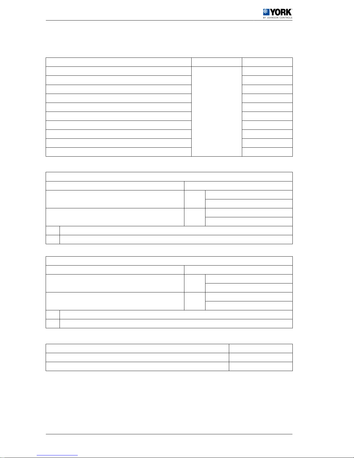
2.2 Start-up data
Electrical data
Rating plate Actual
Power supply
Check specifica‐
tions in the Installa‐
tion Manual
Control voltage
Fan consumption (A)
Consumption of condenser fan 1 (A)
Consumption of condenser fan 2 (A)
Consumption of compressor 1 (A)
Consumption of compressor 2 (A)
Consumption of supply fan (A)
Heating element 1 (Optional)
Heating element 2 (Optional)
Cool and heat modes
Cooling circuit. Compressor 1
Mode Value
Subcooling (min. 8 K, max. 18 K) °C
Liquid pressure: _____ bar
Liquid temperature: _____ °C
Overheating (min. 4 K, max. 10 K) °C
Suction pressure: _____ bar
Suction temperature: _____ °C
Complete liquid line checked in sight glass
Correct oil level checked in sight glass
Cooling circuit. Compressor 2
Mode Value
Subcooling (min. 8 K, max. 18 K) °C
Liquid pressure: _____ bar
Liquid temperature: _____ °C
Overheating (min. 4 K, max. 10 K) °C
Suction pressure: _____ bar
Suction temperature: _____ °C
Complete liquid line checked in sight glass
Correct oil level checked in sight glass
Air flow rate values
m3/h
Design
Measured
2 Unit installation data
2.2 Start-up data
26
Page 29
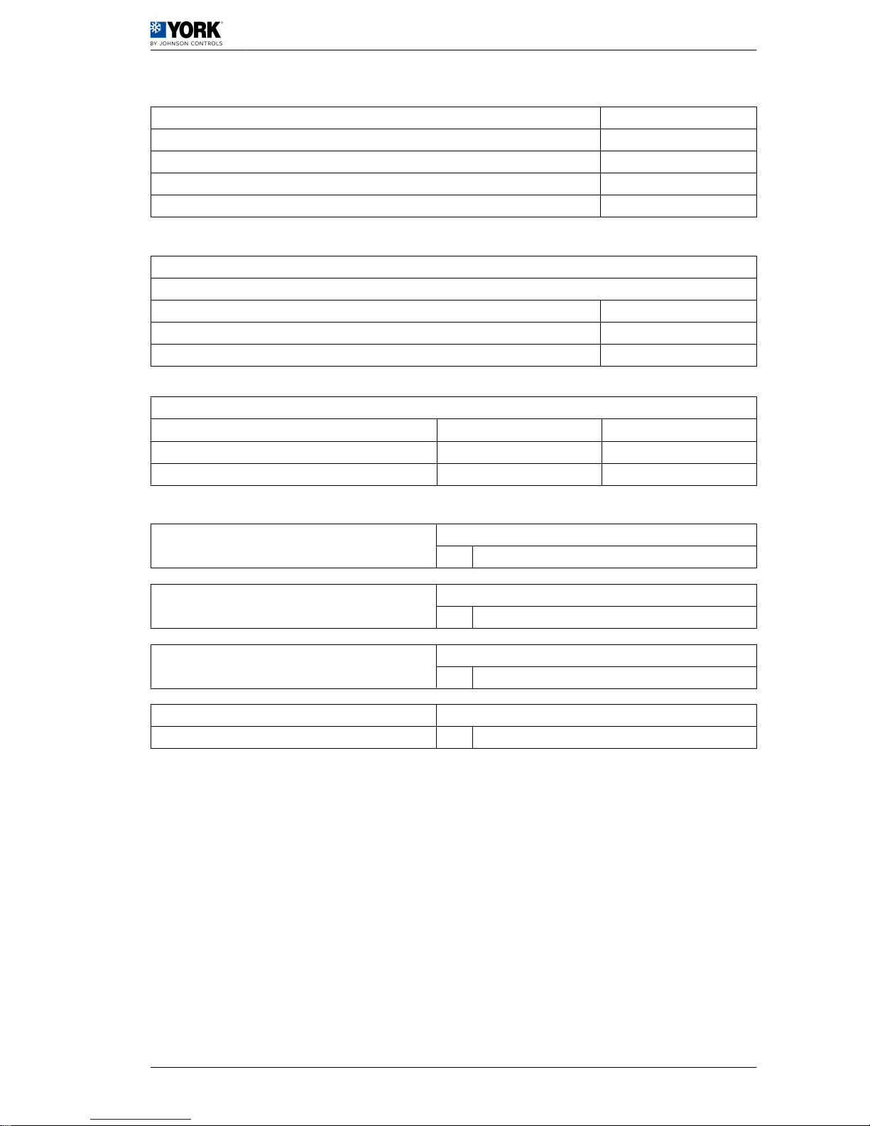
Air temperature
Mode (cool or heat): Temperature (°C)
Outdoor air:
Supply air:
Return air:
Indoor air mix (if economiser is fitted):
Options
Heating mode (hot water coil)
Air temperature
Capacity: _____ (kW) Temperature (°C)
Supply air (at 100 %)
Return air
Hydraulic circuit
Temperature (°C) Pressure (bar)
Water inlet
Water outlet
Others
Outdoor fan 1
Type or model
Surge protection adjusted
Outdoor fan 2
Type or model
Surge protection adjusted
Indoor fan
Type or model
Surge protection adjusted
Belts Type or model
Economiser Minimum outdoor air setting
Unit installation data 2
Start-up data 2.2
27
Page 30
Notes and observations
Notes and observations:
____________________________________________________________________________________
____________________________________________________________________________________
____________________________________________________________________________________
____________________________________________________________________________________
____________________________________________________________________________________
____________________________________________________________________________________
____________________________________________________________________________________
____________________________________________________________________________________
____________________________________________________________________________________
____________________________________________________________________________________
____________________________________________________________________________________
____________________________________________________________________________________
____________________________________________________________________________________
Installed by:
Name
Date and signature
2 Unit installation data
2.2 Start-up data
28
 Loading...