

Page 1
TM
Packaged Roof top
Air Conditioning Units
FORM 100.50-EG3 (802)
Meets ASHRAE 90.1 - 2001
Efficiency Requirements
00566VIP
ASHRAE
90.1
COMPLIANT
50 THROUGH 100 TONS
R-407C and R-22
400VAC/3PH/50Hz
Page 2
Introduction
The eco2 packaged rooftop – Designed to meet the demands of the market for today and tomorrow.
Better Economy...
Reduce Energy Consumption
• High-efficiency eco2 rooftop units are optimized for
both R-22 and HFC-407C refrigerant, and are the
first environmentally responsible rooftop units that
meet the ASHRAE 90.1-2001 ef ficiency standards.
• Multiple steps of capacity-control offer superior of fdesign energy performance, while maintaining better control of occupant comfort.
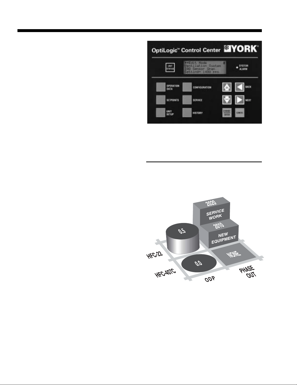
• The OptiLogic
more than the proper amount of ventilation air is
utilized, avoiding the energy cost of conditioning
excess air.
TM
Control Center ensures that no
LD07431
The OptiLogicTM Control Center uses microprocessor logic to optimize operation of the eco2 rooftop unit.
Better Ecology...
Air Quality Features for the Indoor Environment
• A double-sloped stainless steel design ensures that
all condensate is voided from the drain pan. The drain
pan is also visible and accessible for the periodic inspection and cleaning required by IAQ standards.
• Double-wall construction of the roof, floor, doors,
and walls prevents insulation fiber from entering
the supply air. The inner liner also facilitates periodic cleaning of the unit to prevent harmful buildup of bacteria or contaminants.
• The OptiLogicTM Control Center uses microprocessor logic to analyze and optimize ventilation decisions.
• A true airflow-measurement station can be supplied,
to ensure the proper ventilation at all supply-air
volumes.
• An available sensor can monitor the CO2 level within
the building and adjust the ventilation rate on demand, to maintain the air quality at a healthy level.
HFC-407C Refrigerant
for the Global Environment
LD07430
2
YORK INTERNATIONAL
Page 3

TABLE OF CONTENTS
FORM 100.50-EG3 (802)
Introduction.............................................................2
Features and Benefits ............................................4
Nomenclature .........................................................7
Application Data .....................................................8
Physical Data........................................................12
Cooling Performance Data ...................................16
Heating Performance Data – Gas/Electric Heat ...36
Supply Fan Data................................................... 37
Component Static Pressure Drop s .......................40
Gas Heat Pressure Drops ....................................44
Electric Heat Pressure Drops ...............................46
Exhaust Fan Data.................................................48
Component Static Pressure Drop s .......................50
Electrical Data ......................................................52
Controls................................................................54
Power Wiring........................................................60
Field Control Wiring..............................................63
General Arrangement Drawings ...........................64
Curb Layout Drawing ............................................69
Power/Control Entry Drawing................................70
Guide Specifications.............................................71
TABLES
1 Physical Data ................................................. 12
2 Cooling Performance Data – 50 Ton Model....16
3 Cooling Performance Data – 55 Ton Model....18
4 Cooling Performance Data – 60 Ton Model....20
5 Cooling Performance Data – 65 Ton Model....22
6 Cooling Performance Data – 70 Ton Model....24
7 Cooling Performance Data – 75 Ton Model....26
8 Cooling Performance Data – 80 Ton Model....28
9 Cooling Performance Data – 85 Ton Model....30
10 Cooling Performance Data – 90 Ton Model....32
11 Cooling Performance Data – 95 Ton Model....34
12 Gas Heat Performance Data..........................36
13 Electric Heat Performance Data.....................36
14 50 Through 65 T on Supply Fan Data..............37
15 70 Through 85 T on Supply Fan Data..............38
16 90 Through 95 T on Supply Fan Data..............39
17 Component Static Pressure Drops ................. 40
18 Gas Heat Pressure Drops..............................44
19 Electric Heat Pressure Drops.........................46
20 60 Through 65 T on Exhaust Fan Data............48
21 70 Through 85 T on Exhaust Fan Data............49
22 90 Through 95 T on Exhaust Fan Data............49
23 Component Static Pressure Drop s................. 50
24 Compressor Data........................................... 52
25 Supply and Exhaust Fan Motor
Electrical Data................................................ 53
26 Condenser Fan Motors ..................................53
27 Control Transformer....................................... 53
28 Electric Heat...................................................53
29 General Arrangement – 50-65 Ton Models
(Bottom Supply/Bottom Return) ....................... 64
30 General Arrangement – 50-65 Ton Models
(Side Supply/Front Return) ..............................65
31 General Arrangement – 70-95 T on Models
(Bottom Supply/Bottom Return).......................66
32 General Arrangement – 70-95 Ton Models
(Side Supply/Front Return).............................67
33 General Arrangement – 70-95 T on
Optional Side Return......................................68
34 Curb Layout Dimensions................................69
35 Power/Control Dimensions.............................70
FIGURES
1 Single-Point Power Supply Wiring.................. 60
2 Single-Point Power Supply Wiring with
Non-Fused Disconnect .................................. 61
3 Dual-Point Power Supply Wiring ....................62
4 Field Control Wiring .......................................63
5 Gen. Agmt. Dwg. – 50-65 Ton Models
(Bottom Supply/Bottom Return) ...................... 64
6 Gen. Agmt. Dwg. – 50-65 T on Models
(Side Supply/Front Return) ..............................65
7 Gen. Agmt. Dwg. – 70-95 T on Models
(Bottom Supply/Bottom Return) ...................... 66
8 Gen. Agmt. Dwg. – 70-95 Ton Models
(Side Supply/Front Return) ..............................67
9 Gen. Agmt. Dwg. – 70-95 Ton Models
(Optional Side Return) ...................................68
10 Curb Layout Drawing ..................................... 69
1 1 Power/Control Entry Drawing –
50-95 Ton Model ............................................70
YORK INTERNATIONAL
3
Page 4

Features and Benefits
QUALITY ROOFTOP UNIT DESIGNED T O TODA Y’S
STANDARDS
Ecological and Economical Design
• First packaged RTU that meets ASHRAE 90.1-2001
with both R-22 and R-407C Refrigerants.
• Cooling and Heating – Superior operating performance provides lower operating costs. Smaller steps
of cooling capacity provide tighter control of building
environment and occupant comfort while optimizing
energy efficiency .
• Indoor Air Quality (IAQ) – Outside air economizer
provides energy savings in free cooling mode, and
can provide a healthier and more comfortable building environment by introducing fresh outside air into
the building as needed. Indoor Air Quality (IAQ) requirements for building ventilation and comfort are
controlled through the microprocessor control panel.
Optional air flow measurement provides an accurate
means of tracking air quality and alerting the occupants or building owner to unhealthy situations.
• Premium Efficiency – Premium-efficiency motors
are available for optimum energy efficiency. All motors used on the eco2 packaged rooftop air conditioner meet U.S. EP ACT 1992 minimum requirements.
• VFDs Standard on V A V Units – V ariable-frequencydrives provide the HVAC designer with a high-efficiency, quiet and more reliable means of variable air
volume control from a packaged rooftop. On larger
rooftops, ASHRAE 90.1-1999 st andard specifies part
load efficiency requirements that make VFDs the
cost-effective solution for meeting the standard.
VFDs can save the owner up to 40% of the energy
costs compared to inlet guide vanes offered on competitive units by reducing the power requirement.
VFDs use fewer parts, which leads to more reliability . Also, with fewer moving parts, and the reduction
of speed in the fan, the VFD operates at significantly
quieter operation than the inlet guide vane which
restricts a high volume of airflow, which can actually
increase noise at part load conditions.
Additionally, the YORK VFD includes DC link reactors as standard that have harmonic filtration comparable to an AC line reactor. VFDs also provide the
added benefit of soft-starting the supply fan, which
helps to minimize demand charges associated with
inrush currents.
• Network Connectivity with BACnet, LON or Roof-
Link Interface – Through optional communications
protocols, the eco2 rooftop unit can communicate to
any building automation system. There are four options available: BACnet Internet Protocol (Ethernet),
BACnet MSTP (RS485), LON or a generic RoofLink
BAS interface, depending on the type of building
automation system. Without network communications, the eco2 is designed to operate in stand-alone
mode, or via contact closures for basic control.
• Professional Appearance – A high quality powder
coat paint finish is applied to the galvanized steel
2
exterior of the eco
unit to protect it from aggressive
environments helping to maintain a factory-quality
appearance for years.
• FlexSys Underfloor Air System Configuration –
the eco
2
rooftop is the first packaged rooftop product
with designs specifically for use with the YORK FlexSys underfloor air system. Ask your local YORK
representative for more information.
Indoor Air Quality (IAQ)
• Double-Sloped Stainless Steel Drain Pan – This
double-sloped inclined stainless steel drain pan facilitates removal of evaporator condensate. Sloped
in two directions, this drain pan swiftly drains any
condensate from the unit. Best of all, the drain pan
is accessible for periodic cleaning required by IAQ
standards.
• Smart Ventilation – YORK maintains the leadership role in IAQ products with adaptive ventilation
control. The OptiLogic
TM
controls provide continuous
monitoring of air quality and take action by opening
the outside air dampers, bringing in the right amount
of fresh air before air impurities reach uncomfortable
or even dangerous levels.
• Air Flow Measurement – Precise measurement
of ventilation air flow is possible using an air flow
measurement station which can be installed in the
economizer section. Proper ventilation air flow is
required to ensure sufficient fresh air is in the building. A myriad of air flow measurement options are
available from minimum air flow to high-accuracy
full air flow capabilities. The complete system is designed as an integrated component of the
OptiLogicTM control system to ensure optimum system performance.
• Double Wall Construction – Rigid double-wall construction throughout provides ease of cleaning and
protects against insulation fiber entrainment in the
breathable air. Double-wall construction also helps
improve the acoustical characteristics of the air handling unit.
• Enhanced Filtration – The eco2 unit gives designers the flexibility to meet various IAQ requirements
with a full range of rigid and throwaway filter options
at various efficiency levels.
• Demand Ventilation – Control of the economizer
is available to maintain a desired ventilation level
based on a 0-10VDC input from a sensor . A factorysupplied CO2 sensor is available for installation in
the occupied space.
4
YORK INTERNATIONAL
Page 5

FORM 100.50-EG3 (802)
Reliable Cooling and Heating Technology
• Reliable, efficient, trouble-free operation is the true
measure of a packaged rooftop’s value. That’ s why
YORK eco2 Packaged Rooftop Air Conditioners use
established scroll-compressor technology to deliver
dependable, economical performance in a wide
range of applications. With the eco
2
Packaged
Rooftop, you get the latest generation of compressor enhancements added to the scroll’s inherent
strengths. The simplicity of a hermetic scroll compressor allows the use of fewer moving parts to
minimize breakdown. YORK also employs the latest sealing technology to avoid metal-to-metal contact. Axial sealing is accomplished with floating tip
seals, while radial sealing utilizes a microcushion
of oil. The result: a maintenance-free compressor
providing minimum wear and maximum runtime.
• Gas Furnace – The eco2 rooftop gas furnace is an
induced-draft gas furnace designed for high efficiency and reliability. The furnace uses an aluminized steel tubular heat exchanger and operates
at temperatures sufficient to prevent acidic exhaust
gases from condensing in the heat exchanger at
low fire rates, unlike drum and tube style furnaces
that generate condensation formation.
Gas heat units are U.L./C.U.L. listed and are tested
to ANSI standard Z21.47. Multiple modules provide redundancy not available in single power
burner applications.
Serviceability
• Filter Maintenance Alarm – An optional filter maintenance alarm indicates when a filter becomes dirty
and requires replacement or cleaning.
Install with Ease and Safety
• Factory Run-T ested – Each unit is subjected to a
series of quality assurance checks as well as an
automated quality control process before being runtested. Fans and drives are balanced at the factory
during testing. The factory run-test ensures safe,
proper operation when the unit is installed and reduces installation and commissioning time.
• Single-Point Power Connection – Single-point
power connection reduces installation time by providing a single-point for incoming power, including
the optional convenience outlet. All incoming power
is connected in one location, reducing the cost of
distributed power wiring.
• Rain Hoods Rotate Into Place – No bulky , field- in-
stalled rain hoods here. eco2 rain hoods ship rotated
inside the unit. Once on the job, the installer merely
rotates the hood upward, caulks and fastens it in place
with sheet metal screws – an easy , one-person job.
• Factory-mounted and Wired Controls – All control points within the unit are factory-installed, wired
and tested.
• Non-Fused Disconnect – An optional factory-installed non-fused disconnect switch simplifies unit
installation and serviceability by eliminating the need
for a separate disconnect switch. Check local codes
for acceptability .
• OptiLogicTM – Fully-integrated factory-packaged
controls are standard on every unit and include a
display unit with a 4x20 character LCD display.
OptiLogicTM continually monitors all control setpoints
and configurations. If a unit sensor fails, the controller indicates an alarm. If desired, YORK service
can provide remote monitoring and automatically
schedule a service technician to make the repair
and maintain your comfort.
• Access Doors – Full-sized access doors provide
easy access into the unit for routine maintenance
and inspection.
• Suction & Discharge Service Valves – Oversized
service valves to provide isolation and quick reclamation and charging of system refrigerant are available to minimize downtime and simplify the service
and repair task.
• Convenience Outlet – For maintenance tasks requiring power tools, an optional 110V GFCI power
supply can power lights, drills or any other power
hand tool needed.
YORK INTERNATIONAL
Design Flexibility
• Low Ambient Operation – Head-pressure control
is accomplished via a VFD motor controller rather
than an inefficient and noisy condenser fan damper.
By varying the speed of the condenser fan, better
control and quieter operation is obtained during the
cooler weather. Low ambient controls are available
on all systems offering higher mechanical cooling
capacity at low ambient conditions than competitive units.
• Hot Gas Bypass – Optional on constant volume units,
hot gas bypass reduces the cycling of compressors
which helps prolong the life of the equipment.
• Duct Air Openings – Horizontal connections are
available on select configurations, offering more
flexibility for duct layout and improving sound transmission characteristics.
• Compressor Sound Blankets – For applications
in sound-sensitive areas, compressor sound blankets are available to reduce sound emitted from
the rooftop unit.
5
Page 6
Features and Benefits (continued)
• Fan Spring Isolators – One-inch spring isolation
is used to prevent vibration transmission from the
rooftop unit’s supply fan to the building. Two-inch
spring isolation is also available.
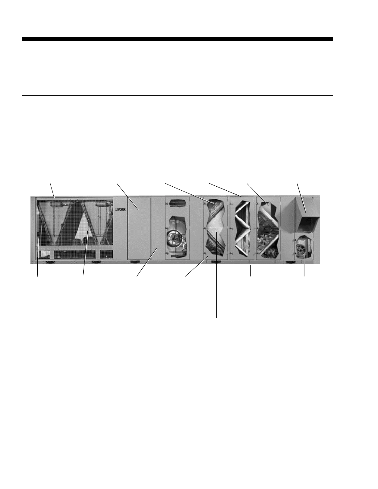
DISTRIBUTOR
OPTIONAL
REPLACEABLE
CORE FILTER
DRIERS
OPTIONAL
HORIZONTAL
SUPPL Y AIR
OPENINGS
TUBES
PROTECTED
IN PLASTIC
SLEEVES
• Harsh Environments – A variety of coil coating and
materials are available as well as hail guards to protect coils from weather damage.
ANGLED OR
RIGID FLAT
FILTER
SECTION
OPTIONAL
AIRFLOW
MEASUREMENT
STATION
RAINHOODS TO
PREVENT
MOISTURE
FROM ENTERING
THE UNIT
FACTORYINSTALLED
OPTILOGIC
ROOFTOP
UNIT
CONTROLLER
V-BANKED
CONDENSER
COILS TO
PROTECT
FROM HAIL
DAMAGE
COMPLETE
DOUBLE-WALL
CONSTRUCTION
OF WALLS,
FLOORS,
CEILING,
AND PANELS
DOUBLE-SLOPED
STAINLESS STEEL
IAQ DRAIN
PAN AND
INTERMEDIATE
DRAIN PAN
ANGLED
EVAPORATOR
COIL FOR
LOWER
FACE
VELOCITIES
DOORS ON BOTH
SIDES OF UNIT
AND TIE BACKS
FOR UNIT
SERVICING
CENTRIFUGAL
FAN POWERED
EXHAUST
00567VIP
6
YORK INTERNATIONAL
Page 7

FORM 100.50-EG3 (802)
NOMENCLATURE
BASIC MODEL NUMBER
1 2 3 4 5 6 7 8 9 10 11 12 13 14 15 16
BASE PRODUCT TYPE NOMINAL CAP ACITY APPLICATION REFRIGERANT VOLTAGE DUCT LOCA TIONS DESIGN SPECIAL
Y 0 5 0 B 45 B A
P055 C L X
: YORK
: Packaged
Rooftop
A065 B
: Air-Cooled
L075 C S
: Scroll
: 50-ton
: 55-ton
: 60-ton
060 RS
: 65-ton
: 70-ton
070 R
: 75-ton
: 80-ton
080 N
: 85-ton
085 G
: 90-ton
090 E
: 95-ton
095 C
: Cooling Only
: Natural Gas Heat
: Natural Gas Heat SS HX
: Electric Heat
: Constant Volume
V
: VAV, VFD
F
: FlexSys
: R-407C
: R-22
: 400 / 3 / 50
: Bottom Supply
: Left Supply
: Right Supply
: Bottom Return
: Front Return
: Side Return
: Rev. Level A
: Special
: Std. Product
YORK INTERNATIONAL
7
Page 8

Application Data
LOCATION
Of the many factors that can affect the acoustical characteristics of a rooftop installation, one of the most important is the unit location. Ideally , the rooftop unit should
be installed away from sound-sensitive areas, such as
conference rooms, auditoriums and executive offices.
Possible locations could be above storage areas, hallways, mechanical or utility rooms, or bathrooms.
The eco
door installation. When selecting a site for installation,
be guided by the following conditions:
• Unit must be installed on a level surface.
• For the outdoor location of the unit, select a place
• Also avoid locations beneath windows or between
• Optional condenser coil protection should be used
• The unit should be installed on a roof that is struc-
• Location of unit(s) should also be away from build-
• Be sure the supporting structures will not obstruct
• Proper service clearance space of 6-feet around
RIGGING
2
air conditioning units are designed for out-
having a minimum sun exposure and an adequate
supply of fresh air for the condenser.
structures.
for seashore locations or other harsh environments.
turally strong enough to support the weight of the
unit with a minimum of deflection. It is recommended that the unit(s) be installed not more than
15 feet from a main support beam to provide proper
structural support and to minimize the transmission
of sound and vibration. Ideally, the center of gravity should be located over a structural support or
building column.
ing flue stacks or exhaust ventilators to prevent possible reintroduction of contaminated air through the
outside air intakes.
the duct, gas or wiring connections.
the perimeter of the unit, 8-feet on one side for coil
servicing, and 12-feet to any adjacent units is required to eliminate cross contamination of exhaust
and outdoor air, and for maintenance tasks such
as coil pull and cleaning. No obstructions should
be above the condensing unit section.
Spreader bars must be used by cranes to prevent damage to the unit casing. All lifting lugs must be used when
lifting the rooftop unit. Fork lifts will damage the roof top
unit and are not recommended.
Care must be taken to keep the unit in the upright position during rigging and to prevent damage to the watertight seams in the unit casing. Avoid unnecessary jarring or rough handling.
Ground Level Locations
It is important that the units be installed on a substantial base that will not settle, causing strain on the refrigerant lines and sheet metal and resulting in possible
leaks. A one-piece concrete slab with footers extended
below the frost line is highly recommended. Additionally , the slab should be isolated from the main building
foundation to prevent noise and vibration transmission
to the building structure.
For ground level installations, precautions should be
taken to protect the unit from tampering by , or injury to,
unauthorized persons. Erecting a fence around the unit
is common practice.
ECONOMIZER
The economizer section is used for ventilation of the
conditioned space to maintain indoor air quality, and
also to reduce energy consumption by using outdoor
air cooling in lieu of mechanical cooling. If outdoor air
is appropriate for cooling, but not sufficient for the cooling demand, mechanical cooling will stage on as necessary until the cooling load is met.
Dual (comparative or differential) enthalpy operation is
the most accurate and efficient means of economizer
operation. The OptiLogicTM control monitors the return
and outside air energy content, and selects the lower of
the two for operation.
V AV SUPPLY AIR PRESSURE CONTROL
Traditional packaged rooftop systems use inlet guide
vanes (IGVs) for duct static pressure control. These control supply duct pressure by modulating dampers (introduc ing losses and inefficiencies) on the inlet of the fan,
open and closed. YORK’s variable frequency drives
(VFDs) offer superior fan speed control and quieter,
energy efficient operation.
Proper rigging and handling of the equipment is mandatory during unloading and setting it into position to
retain warranty status.
8
YORK INTERNATIONAL
Page 9

FORM 100.50-EG3 (802)
For V AV applications, the YORK eco2 unit uses a VFD
to modulate fan speed and maintain a constant duct
static pressure. VFDs offer superior control over the
operation of the unit at part load, and offer the additional benefits of quieter and more efficient operation
when compared to IGV.
HARSH ENVIRONMENTS – CONDENSER AND
EV APORATOR COIL PROTECTION
For harsh environmental conditions such as seashore
applications, YORK offers three types of coil protection: copper fin material, black fin and Technicoat coatings. YORK recommends that for corrosive environments that copper fins be used to protect the evaporator and/or condenser coils. In areas where chemicals
that can corrode copper are present, such as ammonia, YORK recommends that the black fin or Technicoat
coating be used for maximum protection.
Copper Fin Condenser Coil
Copper fins can be used instead of aluminum for additional corrosion protection, however it is not suitable
for areas that are subject to acid rain or exposed to
ammonia.
Pre-Coated Condenser Fins
Black fin coating (yellow fin for evaporator fins) is precoated application epoxy on aluminum fin stock to guard
from corrosive agents and insulate against galvanic potential. It is used for mild seashore or industrial locations. This can provide corrosion resistance comparable
to copper fin coils in typical seashore locations.
Post-Coated Condenser Fins
T echnicoat (a post-coated application of epoxy) can be
used for seashore and other corrosive applications with
the exception of strong alkaloides, oxidizers, wet bromide, chlorine and fluorine in concentrations greater
than 100 ppm.
Any of the above suitable options should be selected
based on the particular project design parameters and
related environmental factors. The application should
be further reviewed and approved by the consulting engineer or owner based on their knowledge of the job
site conditions.
BUILDING EXHAUST SYSTEMS
Building exhaust systems are often necessary when
economizers are used to bring in outdoor air. Without
proper building exhaust, the building may become overpressurized. The exhaust system maintains the proper
building pressure by expelling the appropriate amount
of air from the building. Exhaust systems are typically
designed to exhaust approximately 10% less air than
what is entering the building. This provides a slight positive pressure in the building.
100% modulating exhaust with building static
pressure sensing and control
The 100% exhaust system can be configured with either control actuated dampers or VFDs for modulating
control. The unit controller monitors the building pressure using a differential pressure transducer and maintains the required building static pressure by modulating the exhaust control. If the building has other means
of exhaust or building pressure is not important, on/off
or barometric control may be used.
Powered exhaust with fan on/off control
The 100% exhaust system can be configured for on/off
operation eliminating the expense of the damper actuators or VFDs. This exhaust system can be controlled
by either the outside air damper position, or a building
static pressure sensor.
Barometric exhaust
Barometric exhaust can be used when smaller amounts
of air at low static pressure variations within the building or other means of building exhaust are employed.
Barometric exhaust is commonly used where there are
only small fluctuations in building pressure or where
building static pressure control is not necessary .
ROOF CURB
YORK offers optional roof curbs designed specifically
for the eco
2
footprint. These curbs come disassembled
and require field assembly and installation. For bottom
supply and return openings, the curbs have matching
connections to ease installation. A pipe chase that
matches the rooftop unit pipe chase is also included in
the curb footprint for through-the-curb utility connections.
YORK INTERNATIONAL
9
Page 10

Application Data (continued)
The curb should be located according to the location
recommendations above, and properly sealed to prevent moisture and air leakage into and out of the duct
system. Flexible collars should be used when connecting the duct work to prevent unit noise transmission
and vibration into the building.
Duct work should be supported independently of the
unit.
ACOUSTICAL CONSIDERA TIONS
The eco
competitive units by using flexible fan connections, fan
spring isolators, double-wall construction, and lower
speed and horsepower fans. For VAV applications,
VFDs are used instead of inlet guide vanes. Additional
sound attenuation can be obtained using compressor
sound blankets and field-supplied sound attenuators
when necessary.
Even with these equipment design features, the acoustical characteristics of the entire installation must never
be overlooked. Additional steps for the acoustical characteristics of a rooftop installation should be addressed
during the design phase of a project to avoid costly alterations after the installation of the equipment. During
the design phase of a project, the designing engineer
should consider, at a minimum, the imp act of the equipment location, rooftop installation, building structure, and
duct work.
2
unit is designed for lower sound levels than
Select Unit:
1. Determine the internal static pressure drop of the
cabinet by referencing Table 17.
Wet evaporator coil 0.58
Bottom return opening 0.15
Two-inch pleated filters 0.12
Mod. econ. dampers 0.56
Total 1.41 IWG
2. Determine the total static pressure by adding the
internal to the external static pressure.
TSP = 1.41 IWG + 2.25 IWG = 3.66 IWG total static pressure
3. Determine the BHP of the supply fan from Table 15
using the supply air flow and total static pressure.
From the table, we interpolate to get 26.3 BHP at
724 rpm.
4. Determine the motor heat gain of supply air flow by
first calculating the motor energy and converting it
into Btuh.
Motor Energy
Motor kW = BHP x .746/efficiency
Motor kW = 26.3 x 0.746/0.94
Motor kW = 20.9 kW
SELECTION PROCEDURE
Given:
Total Cooling Load 920 mbh
Sensible Heat 610 mbh
Required Heating Capacity 875 mbh
Design Cooling Ambient Temp. 95°F
Indoor Air Temperature 80°F db/67°F wb
Supply Air Flow 24,000 cfm
External Static Pressure 2.25 in. w.c.
Electrical Service 460V/3ph/60 Hz
Unit Configuration/Options: 0-100% modulating economizer, barometric relief, premium ef ficiency supply fan
motor and VFD, and two-inch pleated filters, bottom
supply, bottom return.
10
Motor Heat Rejection (MHR)
MHR = 2545 x BHP/efficiency
MHR = 2545 x 26.3/0.94
MHR = 71.2 mbh
5. Calculate actual required tot al cooling capacity by
adding specified cooling capacity to motor heat
rejection.
Required T ot al Cooling Capacity
920 mbh + 71.3 mbh = 991 mbh
Required Sensible Cooling Capacity
610 mbh + 71.3 mbh = 681 mbh
YORK INTERNATIONAL
Page 11

FORM 100.50-EG3 (802)
6. Required total and sensible capacities are 991 mbh
and 681 mbh, respectively . The total capacity is 82.6
tons, therefore a model YP AL085 is selected. Use
the Cooling Performance Data in Table 9. Locate
the table with the correct ambient air temperature.
Next, trace the 80°F entering air dry bulb temperature to match the 24,000 cfm and 67°F entering
wet bulb temperature condition. The resulting conditions are, from the table, 996.5 mbh total cooling
capacity and 688.9 mbh sensible cooling capacity .
7. The high heat option for the YPAL085 provides
900 mbh of heat capacity with an input of 1,125
mbh. This is sufficient for the 875 mbh heating
requirement.
8. Determine net cooling and heating capacities if
required.
Net Cooling Capacity (NCC)
mbh = 996.5 mbh – 71.3 mbh
mbh = 925 mbh
Net Sensible Heat Capacity (NSHC)
mbh = 688.9 mbh - 71.3 mbh
mbh = 618 mbh
Net Heating Capacity (NHC)*
mbh = 875 mbh + 71.3 mbh
mbh = 946 mbh
* Note, net heating capacity is approximate because this example
uses the bhp calculated based on a wet evaporator coil (for
cooling mode).
YORK INTERNATIONAL
11
Page 12

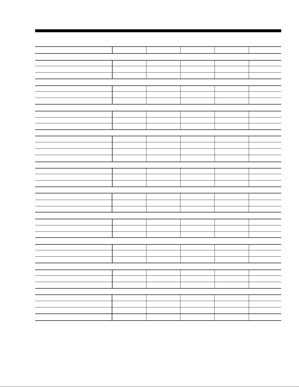
Physical Data
T ABLE 1 – PHYSICAL DATA – MODELS 50-70
MODEL SIZE 050 055 060 065 070
GENERAL DATA
Length (cm) w/o Hood 874 874 874 874 1140
Width (cm) w/o Hood 234 234 234 234 234
Height (cm) 208 208 208 208 208
Operating Weights (Kg) (Base Unit, No Options)
Cooling Only (Rigging & R407C) 3701 3797 3934 4029 5799
Option Weights (Kg)
Power Exhaust (Blower, Motor, Fan Skid & Mod Damper) 284 284 284 284 341
Power Exhaust (Blower, Motor, Fan Dkid, VFD & Baro Damper) 287 287 287 287 332
100% AMS (Measurement Station & Mounting) 50 50 50 50 57
25/75% AMS (Measurement Station & Mounting) 59 59 59 59 66
Min. AMS (Measurement Station & Mounting) 18 18 18 18 20
Barometric Only 16 16 16 16 20
375 MBH Gas Heat 73 73 73 73 73
750 MBH Gas Heat 147 147 147 147 147
1125 MBH Gas Heat n/a n/a n/a n/a 220
40 kW 195 195 195 195 204
80 kW 222 222 222 222 231
108 kW 204 204 204 204 213
150 kW 213 213 213 213 222
200 kW 222 222 222 222 231
250 kW 231 231 231 231 240
Condenser Wire Guard 15 15 15 15 18
Copper Condenser Coils (additional) 280 280 360 360 280
Copper Evaporator Coils (additional) 119 145 181 227 127
Roof Curb Weights (Kg)
14" Full Perimeter Roof Curb 374 374 374 374 463
14" Open Condenser Roof Curb 252 252 252 252 262
Compressor Data
Quantity/Size (Nominal HP) 4x13 4x13 4x15 4x15 4x10, 2x13
Type Scroll Scroll Scroll Scroll Scroll
Capacity Steps (%) 4x25 4x25 4x25 4x25 4x15, 2x20
Supply Fan and Drive
Quantity 1 1 1 1 1
Type FC FC FC FC FC
Size 25-22 25-22 25-22 25-22 28-25
Motor Size Range (Min. to Max. HP) 7.5-40 7.5-40 7.5-40 7.5-40 7.5-60
Air Flow Range (Min. to Max. m3/hr) 16,988-38,228 16,988-38,228 23785-45875 23785-45875 23785-54,367
Static Pressure Range (Min. to Max. ESP) 0-995 Pa 0-995 Pa 0-995 Pa 0-995 Pa 0-995 Pa
Exhaust Fan
Quantity 2 2 2 2 2
Type FC FC FC FC FC
Size 15-15 15-15 15-15 15-15 18-18
Motor Size Range (Min. to Max. HP) 5-20 5-20 5-20 5-20 10-20
Air Flow Range (Min. to Max. m3/hr) 0-33980 0-33980 0-33980 0-33980 0-33980
Static Pressure Range (Min. to Max. ESP) 0-498 Pa 0-498 Pa 0-498 Pa 0-498 Pa 0-498 Pa
12
YORK INTERNATIONAL
Page 13
FORM 100.50-EG3 (802)
T ABLE 1 – PHYSICAL DATA – MODELS 50-70 (CONT’D)
MODEL SIZE 050 055 060 065 070
Evaporator Coil
Size (Square Meters) 5 5 5 5 5
Number of Rows/Fins per cm 1 1 1 1 1
Tube Diameter (cm) /Surface 5/4 /enhanced 5/4 /enhanced 5/4 /enhanced 5/4 /enhanced 5/4 /enhanced
Condenser Coil (Aluminum Fins)
Size (Square Meters) 11 11 11 11 182
Number of Rows/Fins per cm 1 1 0 0 0
Tube Diameter (cm) 1 1 1 1 1
Condenser Coil (Copper Fins - Opt)
Size (square meters) 11 11 11 11 17
Number of rows/fins per cm 1 1 0 0 0
Tube Diameter 1 1 1 1 1
Condenser Fans
Quantity 4 4 4 4 6
Type Prop. Prop. Prop. Prop. Prop.
Diameter (Meters) 1 1 1 1 1
Power (Hp Each) 2 2 2 2 2
Filters - 5.08cm Throwaway
Quantity 8 / 12 8 / 12 8 / 12 8 / 12 10 / 15
Size (Length x Width) (Meters) .6x.4 / .6x.5 .6x.4 / .6x.5 .6x.4 / .6x.5 .6x.4 / .6x.5 .6x.4 / .6x.5
Total Filter Face Area (Square Meters) 6 6 6 6 7
Filters - 5.08cm Cleanable
Quantity 8 / 12 8 / 12 8 / 12 8 / 12 10 / 15
Size (Length x Width) (Meters) .6x.4 / .6x.5 .6x.4 / .6x.5 .6x.4 / .6x.5 .6x.4 / .6x.5 .6x.4 / .6x.5
Total Filter Face Area (Square Meters) 6 6 6 6 7
Filters - 5.08cm Pleated (30% Efficient)
Quantity 8 / 12 8 / 12 8 / 12 8 / 12 10 / 15
Size (Length x Width) (Meters) .6x.4 / .6x.5 .6x.4 / .6x.5 .6x.4 / .6x.5 .6x.4 / .6x.5 .6x.4 / .6x.5
Total Filter Face Area (Square Meters) 6 6 6 6 7
Filters -30.48cm Rigid 65%, 5.08cm 30% Prefilter
Quantity 1 / 4 / 9 1 / 4 / 9 1 / 4 / 9 1 / 4 / 9 2 / 8 / 9
Size (Length x Width) (Meters) .4x.5 /.6x.4 /.6x.5 .4x.5 /.6x.4 /.6x.5 .4x.5 /.6x.4 /.6x.5 .4x.5 /.6x.4 /.6x.5 .4x.5 /.6x.4 /.6x.5
Total Filter Face Area (Square Meters) 1 1 1 1 1
Filters -30.48cm Rigid 95%, 5.08cm 30% Prefilter
Quantity 1 / 4 / 9 1 / 4 / 9 1 / 4 / 9 1 / 4 / 9 2 / 8 / 9
Size (Length x Width) (Meters) .4x.5 /.6x.4 /.6x.5 .4x.5 /.6x.4 /.6x.5 .4x.5 /.6x.4 /.6x.5 .4x.5 /.6x.4 /.6x.5 .4x.5 /.6x.4 /.6x.5
Total Filter Face Area (Square Meters) 1 1 1 1 1
Filters - 5.08cm Carbon (30% Efficient)
Quantity 1 / 4 / 9 1 / 4 / 9 1 / 4 / 9 1 / 4 / 9 10 / 15
Size (Length x Width) (Meters) .4x.5 /.6x.4 /.6x.5 .4x.5 /.6x.4 /.6x.5 .4x.5 /.6x.4 /.6x.5 .4x.5 /.6x.4 /.6x.5 .6x.4 / .6x.5
Total Filter Face Area (Square Meters) 1 1 1 1 2
Minimum OA Temp. for Mech. Cig. 45 45 45 45 45
YORK INTERNATIONAL
13
Page 14
Physical Data (continued)
T ABLE 1 – PHYSICAL DATA – MODELS 75-95
MODEL SIZE 075 080 085 090 095
GENERAL DATA
Length (cm) w/o Hood 1140 1140 1140 1240 1240
Width (cm) w/o Hood 234 234 234 234 234
Height (cm) 208 208 208 234 234
Operating Weights (Kg) (Base Unit, No Options)
Cooling Only (Rigging & R407C) 5897 5994 6092 6496 6594
Option Weights (Kg)
Power Exhaust (Blower, Motor, Fan Skid & Mod Damper) 341 341 341 347 347
Power Exhaust (Blower, Motor, Fan Skid, VFD & Baro Damper) 332 332 332 337 337
100% AMS (Measurement Station & Mounting) 57 57 57 64 64
25/75% AMS (Measurement Station & Mounting) 66 66 66 73 73
Min. AMS (Measurement Station & Mounting) 20 20 20 23 23
Barometric Only 20 20 20 25 25
375 MBH Gas Heat 73 73 73 73 73
750 MBH Gas Heat 147 147 147 147 147
1125 MBH Gas Heat 220 220 220 220 220
40 kW 204 204 204 222 222
80 kW 231 231 231 249 249
108 kW 213 213 213 231 231
150 kW 222 222 222 240 240
200 kW 231 231 231 249 249
250 kW 240 240 240 259 259
Condenser Wire Guard 18 18 18 20 20
Copper Condenser Coils (Additional) 280 480 480 540 540
Copper Evaporator Coils (Additional) 209 127 209 209 263
Roof Curb Weights (Kg)
14" Full Perimeter Roof Curb 463 463 463 472 472
14" Open Condenser Roof Curb 262 262 262 279 279
Compressor Data
Quantity/Size (Nominal Hp) 4x10, 2x13 6x13 6x13 2x13, 4x15 2x13, 4x15
Type Scroll Scroll Scroll Scroll Scroll
Capacity Steps (%) 4x15, 2x20 6x16 6x16 4x18, 2x15 4x18, 2x15
Supply Fan and Drive
Quantity 1 1 1 1 1
Type FC FC FC FC FC
Size 28-25 28-25 28-25 28-28 28-28
Motor Size Range (Min. to Max. Hp) 7.5-60 7.5-60 7.5-60 7.5-60 7.5-60
Air Flow Range (Min. to Max. m3/hr) 23785-54,367 23785-54,367 30582-61164 30582-61164 30582-61164
Static Pressure Range (Min. to Max. ESP) 0-995 Pa 0-995 Pa 0-995 Pa 0-995 Pa 0-995 Pa
Exhaust Fan
Quantity 2 2 2 2 2
Type FC FC FC FC FC
Size 18-18 18-18 18-18 18-18 18-18
Motor Size Range (Min. to Max. HP) 10-20 10-20 10-20 10-20 10-20
Air Flow Range (Min. to Max. m3/hr) 0-33980 0-33980 0-33980 0-33980 0-33980
Static Pressure Range (Min. to Max. ESP) 0-498 Pa 0-498 Pa 0-498 Pa 0-498 Pa 0-498 Pa
14
YORK INTERNATIONAL
Page 15

FORM 100.50-EG3 (802)
T ABLE 1 – PHYSICAL DATA – MODELS 75-95 (CONT’D)
MODEL SIZE 075 080 085 090 095
Evaporator Coil
Size (Square Meters) 5 5 5 5 5
Number of Rows/Fins per cm 1 1 1 1 1
Tube Diameter (cm) /Surface 5/4 /enhanced 5/4 /enhanced 5/4 /enhanced 5/4 /enhanced 5/4 /enhanced
Condenser Coil (Aluminum Fins)
Size (Square Meters) 17 17 17 17 17
Number of Rows/Fins per cm 0 0 0 0 0
Tube Diameter (cm) 1 1 1 1 1
Condenser Coil (Copper Fins - Opt)
Size (Square Meters) 17 17 17 17 17
Number of Rows/Fins per cm 0 0 0 0 0
Tube Diameter 1 1 1 1 1
Condenser Fans
Quantity 6 6 6 6 6
Type Prop. Prop. Prop. Prop. Prop.
Diameter (Meters) 1 1 1 1 1
Power (Hp Each) 2 2 2 2 2
Filters - 5.08cm Throwaway
Quantity 10 / 15 10 / 15 10 / 15 12 / 18 12 / 18
Size (Length x Width) (Meters) 6x.4 / .6x.5 .6x.4 / .6x.5 .6x.4 / .6x.5 .6x.4 / .6x.5 .6x.4 / .6x.5
Total Filter Face Area (Square Meters) 7 7 7 9 9
Filters - 5.08cm Cleanable
Quantity 10 / 15 10 / 15 10 / 15 12 / 18 12 / 18
Size (Length x Width) (Meters) .6x.4 / .6x.5 .6x.4 / .6x.5 .6x.4 / .6x.5 .6x.4 / .6x.5 .6x.4 / .6x.5
Total Filter Face Area (Square Meters) 7 7 7 9 9
Filters - 5.08cm Pleated (30% Efficient)
Quantity 10 / 15 10 / 15 10 / 15 12 / 18 12 / 18
Size (Length x Width) (Meters) .6x.4 / .6x.5 .6x.4 / .6x.5 .6x.4 / .6x.5 .6x.4 / .6x.5 .6x.4 / .6x.5
Total Filter Face Area (Square Meters) 7 7 7 9 9
Filters -30.48cm Rigid 65%, 5.08cm 30% Prefilter
Quantity 2 / 8 / 9 2 / 8 / 9 2 / 8 / 9 8 / 12 8 / 12
Size (Length x Width) (Meters) .4x.5 /.6x.4 /.6x.5 .4x.5 /.6x.4 /.6x.5 .4x.5 /.6x.4 /.6x.5 .6x.4 / .6x.5 .6x.4 / .6x.5
Total Filter Face Area (Square Meters) 1 1 1 2 2
Filters -30.48cm Rigid 95%, 5.08cm 30% Prefilter
Quantity 2 / 8 / 9 2 / 8 / 9 2 / 8 / 9 8 / 12 8 / 12
Size (Length x Width) (Meters) .4x.5 /.6x.4 /.6x.5 .4x.5 /.6x.4 /.6x.5 .4x.5 /.6x.4 /.6x.5 .6x.4 / .6x.5 .6x.4 / .6x.5
Total Filter Face Area (Square Meters) 1 1 1 2 2
Filters - 5.08cm Carbon (30% Efficient)
Quantity 10 / 15 10 / 15 10 / 15 12 / 18 12 / 18
Size (Length x Width) (Meters) .6x.4 / .6x.5 .6x.4 / .6x.5 .6x.4 / .6x.5 .6x.4 / .6x.5 .6x.4 / .6x.5
Total Filter Face Area (Square Meters) 2 2 2 2 2
Minimum OA Temp. for Mech. Cig. 45 45 45 45 45
YORK INTERNATIONAL
15
Page 16

Cooling Performance Data – 50 Ton Model
T ABLE 2 – COOLING PERFORMANCE DA TA* – 50 TON MODEL
29.4°C AIR ON CONDENSER COIL
CAPACITY (kW) AT ENTERING DRY BULB (°C)
m3/hr
22653 19 179 162 175 148 173 134 173 121 171 108 170 96
25485 19 180 165 175 150 173 135 173 122 172 109 171 97
29733 19 181 168 176 152 175 138 174 124 173 110 172 97
31148 19 186 184 181 163 180 147 179 130 178 115 176 100
ENTERING
WB (°C) CAP SHC CAP SHC CAP SHC CAP SHC CAP SHC CAP SHC
22 189 141 188 125 187 111 186 99 186 86 – –
17 179 179 170 172 164 169 160 156 156 143 157 125
22 190 143 189 126 188 112 187 100 187 8 6 – –
17 180 180 172 174 166 168 161 153 157 140 158 122
22 191 146 190 128 189 113 188 101 187 8 7 – –
17 181 181 173 176 167 164 162 150 158 137 159 119
22 196 156 193 134 193 119 192 104 191 8 9 – –
17 189 189 181 183 175 179 167 158 165 144 164 126
32 30 28 27 25 23
* Rated performance is at sea level. Cooling capacities are gross cooling capacity.
35°C AIR ON CONDENSER COIL
CAPACITY (kW) AT ENTERING DRY BULB (°C)
m3/hr
22653 19 173 159 170 146 167 131 167 118 165 107 164 93
25485 19 174 162 171 148 168 133 168 119 166 107 165 94
29733 19 175 165 171 150 169 135 169 120 167 107 166 94
31148 19 182 182 175 159 174 144 173 128 171 109 170 9 7
* Rated performance is at sea level. Cooling capacities are gross cooling capacity.
ENTERING
WB (°C) CAP SHC CAP SHC CAP SHC CAP SHC CAP SHC CAP SHC
22 182 138 181 121 180 108 180 96 179 83
17 173 173 166 167 159 150 156 140 153 128 153 114
22 183 140 182 123 181 109 180 97 180 84 – –
17 175 175 167 169 160 152 157 142 154 130 154 115
22 184 143 183 124 182 110 181 97 180 84 – –
17 177 177 169 171 162 155 158 144 155 132 155 117
22 188 153 187 132 186 116 185 101 184 8 7 – –
17 184 184 176 178 169 169 162 153 159 140 159 125
32 30 28 27 25 23
16
YORK INTERNATIONAL
Page 17

FORM 100.50-EG3 (802)
T ABLE 2 – COOLING PERFORMANCE DATA* – 50 TON MODEL (CONT’D)
40.5°C AIR ON CONDENSER COIL
CAPACITY (kW) AT ENTERING DRY BULB (°C)
m3/hr
22653 19 164 154 162 142 160 128 160 114 160 102 159 90
25485 19 165 156 163 144 161 130 161 115 161 103 160 90
29733 19 167 160 164 146 162 132 162 117 162 104 161 91
31148 19 175 177 169 157 167 141 166 125 165 109 164 9 4
ENTERING
WB (°C) CAP SHC CAP SHC CAP SHC CAP SHC CAP SHC CAP SHC
22 175 136 175 119 174 105 173 93 173 80 – –
17 168 168 161 163 150 147 150 135 148 126 147 111
22 176 138 176 120 174 106 174 94 173 81 – –
17 169 169 162 164 152 149 151 137 149 127 148 113
22 177 140 176 122 175 108 175 95 174 81 – –
17 171 171 164 166 154 152 152 140 150 129 149 114
22 181 149 180 129 179 113 178 98 177 83 – –
17 179 179 171 173 163 164 155 151 153 137 152 120
32 30 28 27 25 23
* Rated performance is at sea level. Cooling capacities are gross cooling capacity.
46.1°C AIR ON CONDENSER COIL
CAP ACITY (kW) AT ENTERING DRY BULB (°C)
m3/hr
22653 19 159 153 155 138 154 126 152 112 151 99 151 87
25485 19 160 156 156 140 154 127 153 113 152 100 151 87
29733 19 162 158 157 142 155 129 154 114 153 101 152 88
31148 19 169 172 160 151 160 137 159 121 158 106 156 9 1
* Rated performance is at sea level. Cooling capacities are gross cooling capacity.
ENTERING
WB (°C) CAP SHC CAP SHC CAP SHC CAP SHC CAP SHC CAP SHC
22 168 133 167 115 165 101 164 90 163 78
17 161 161 154 156 145 147 142 132 140 123 139 109
22 169 135 168 116 166 102 165 90 164 78 – –
17 163 163 155 157 147 149 143 135 140 124 139 110
22 170 137 169 118 167 104 166 91 165 79 – –
17 165 165 157 158 149 151 144 138 142 126 140 111
22 174 147 172 125 171 109 170 95 169 80 – –
17 172 172 163 165 157 160 150 150 146 134 145 118
32 30 28 27 25 23
YORK INTERNATIONAL
17
Page 18

Cooling Performance Data – 55 Ton Model
T ABLE 3 – COOLING PERFORMANCE DA TA* – 55 TON MODEL
29.4°C AIR ON CONDENSER COIL
CAPACITY (kW) AT ENTERING DRY BULB (°C)
m3/hr
20388 19 185 167 181 153 181 139 182 125 180 113 178 100
27184 19 192 186 186 166 186 150 186 134 185 119 183 104
32706 19 202 2 11 193 183 193 164 192 145 192 127 190 109
33980 19 204 213 194 185 193 166 193 147 193 128 191 110
ENTERING
WB (°C) CAP SHC CAP SHC CAP SHC CAP SHC CAP SHC CAP SHC
22 197 148 197 130 196 116 195 103 194 8 9 – –
17 183 183 175 178 166 171 167 147 166 136 166 123
22 202 159 201 138 201 123 200 107 198 92 – –
17 193 193 185 187 177 174 173 159 171 146 171 131
22 209 175 207 150 207 132 206 113 204 96 – –
17 206 206 197 199 190 195 180 176 178 159 177 141
22 210 177 208 151 208 133 206 114 205 96 – –
17 208 208 199 201 192 197 181 178 179 161 178 143
32 30 28 27 25 23
* Rated performance is at sea level. Cooling capacities are gross cooling capacity.
35°C AIR ON CONDENSER COIL
CAP ACITY (kW) AT ENTERING DRY BULB (°C)
m3/hr
20388 19 178 162 175 150 175 136 175 122 174 113 173 97
27184 19 186 182 180 162 179 147 179 131 178 113 177 101
32706 19 197 205 187 178 186 162 185 143 184 122 183 106
33980 19 198 207 187 180 187 164 186 144 185 123 184 107
* Rated performance is at sea level. Cooling capacities are gross cooling capacity.
ENTERING
WB (°C) CAP SHC CAP SHC CAP SHC CAP SHC CAP SHC CAP SHC
22 190 145 190 126 189 113 189 100 187 8 7 – –
17 178 178 171 173 163 167 162 145 161 133 160 119
22 195 156 194 135 193 120 193 107 192 89 – –
17 188 188 180 182 172 170 167 156 165 143 165 128
22 201 171 200 148 199 129 198 129 197 92 – –
17 200 200 192 194 184 189 173 171 171 157 171 140
22 202 173 201 149 200 130 199 132 198 92 – –
17 202 202 193 196 185 190 174 173 172 158 172 142
32 30 28 27 25 23
18
YORK INTERNATIONAL
Page 19
FORM 100.50-EG3 (802)
T ABLE 3 – COOLING PERFORMANCE DATA* – 55 TON MODEL (CONT’D)
40.5°C AIR ON CONDENSER COIL
CAP ACITY (kW) AT ENTERING DRY BULB (°C)
m3/hr
20388 19 166 159 164 144 162 130 161 116 161 104 161 91
27184 19 175 174 169 157 168 141 167 125 165 111 165 96
32706 19 191 200 181 176 180 159 179 140 175 121 177 104
33980 19 194 202 183 179 181 161 181 142 177 123 178 105
ENTERING
WB (°C) CAP SHC CAP SHC CAP SHC CAP SHC CAP SHC CAP SHC
22 177 139 175 120 174 106 173 94 172 80 – –
17 166 166 160 162 152 151 149 137 147 127 146 113
22 182 150 181 130 180 115 180 105 178 84 – –
17 177 177 170 172 162 164 156 153 154 137 153 121
22 193 166 193 144 193 127 191 128 190 90 – –
17 195 195 186 188 179 184 167 174 165 153 164 135
22 195 168 194 146 194 128 193 131 192 91 – –
17 197 197 188 190 182 187 169 176 167 156 166 137
32 30 28 27 25 23
* Rated performance is at sea level. Cooling capacities are gross cooling capacity.
46.1°C AIR ON CONDENSER COIL
CAP ACITY (kW) AT ENTERING DRY BULB (°C)
m3/hr
20388 19 166 158 164 144 161 130 161 115 161 104 160 91
27184 19 173 173 166 154 165 140 165 124 164 110 164 95
32706 19 184 192 170 169 171 154 171 136 169 118 168 100
33980 19 185 193 171 171 172 156 172 137 170 119 169 101
* Rated performance is at sea level. Cooling capacities are gross cooling capacity.
ENTERING
WB (°C) CAP SHC CAP SHC CAP SHC CAP SHC CAP SHC CAP SHC
22 177 139 175 119 174 106 173 94 172 80 – –
17 166 166 160 162 152 151 149 137 147 126 146 113
22 181 150 179 129 178 113 177 98 176 83 – –
17 175 175 166 168 160 162 155 152 152 136 151 121
22 185 165 185 141 183 122 184 105 181 87 – –
17 187 187 175 176 172 177 164 172 158 150 157 131
22 186 167 185 143 184 123 185 106 182 87 – –
17 189 189 176 178 173 178 165 173 159 151 158 133
32 30 28 27 25 23
YORK INTERNATIONAL
19
Page 20

Cooling Performance Data – 60 Ton Model
T ABLE 4 – COOLING PERFORMANCE DA TA* – 60 TON MODEL
29.4°C AIR ON CONDENSER COIL
CAPACITY (kW) AT ENTERING DRY BULB (°C)
m3/hr
23786 19 213 199 205 177 205 147 204 144 204 129 202 113
30582 19 224 225 213 199 213 173 212 160 212 141 210 121
35679 19 232 242 219 215 219 195 218 171 217 149 215 126
38228 19 234 244 221 219 220 201 219 174 219 151 216 127
ENTERING
WB (°C) CAP SHC CAP SHC CAP SHC CAP SHC CAP SHC CAP SHC
22 224 170 223 150 222 119 221 117 219 101 – –
17 209 209 200 203 196 169 189 175 186 160 187 139
22 232 192 229 165 229 138 228 125 226 106 – –
17 225 225 215 218 208 202 198 192 196 180 195 170
22 238 208 234 176 233 156 232 131 231 110 – –
17 237 237 226 228 217 224 204 205 203 199 201 195
22 239 213 235 178 234 161 233 133 232 111 – –
17 239 239 229 231 220 226 206 208 205 204 203 202
32 30 28 27 25 23
* Rated performance is at sea level. Cooling capacities are gross cooling capacity.
35°C AIR ON CONDENSER COIL
CAP ACITY (kW) AT ENTERING DRY BULB (°C)
m3/hr
23786 19 208 186 199 160 198 154 197 141 196 127 195 110
30582 19 218 216 210 182 206 173 205 156 203 133 202 117
35679 19 225 235 218 210 212 191 210 167 208 142 207 123
38228 19 227 236 221 217 213 196 211 170 209 144 208 124
* Rated performance is at sea level. Cooling capacities are gross cooling capacity.
ENTERING
WB (°C) CAP SHC CAP SHC CAP SHC CAP SHC CAP SHC CAP SHC
22 216 167 214 146 213 126 213 113 2 11 98 – –
17 204 204 195 197 188 179 184 168 182 153 183 135
22 223 188 221 162 220 139 219 122 218 103 – –
17 219 219 209 211 201 199 192 187 187 179 184 169
22 229 204 226 174 225 151 223 129 222 107 – –
17 229 229 219 222 210 216 198 201 191 198 185 192
22 230 208 227 177 226 155 225 130 223 108 – –
17 232 232 222 224 213 219 199 205 192 202 186 195
32 30 28 27 25 23
20
YORK INTERNATIONAL
Page 21

FORM 100.50-EG3 (802)
T ABLE 4 – COOLING PERFORMANCE DATA* – 60 TON MODEL (CONT’D)
40.5°C AIR ON CONDENSER COIL
CAP ACITY (kW) AT ENTERING DRY BULB (°C)
m3/hr
23786 19 200 187 190 171 190 154 190 137 189 122 188 106
30582 19 210 208 198 188 197 172 197 152 195 133 194 11 4
35679 19 218 227 204 209 203 185 201 163 199 141 198 11 9
38228 19 220 229 206 217 204 189 202 166 200 144 199 121
ENTERING
WB (°C) CAP SHC CAP SHC CAP SHC CAP SHC CAP SHC CAP SHC
22 208 165 206 143 205 126 205 110 204 94 – –
17 197 197 189 191 179 179 177 163 175 150 175 133
22 213 182 212 158 211 139 210 119 209 99 – –
17 211 211 202 205 193 197 185 183 180 166 181 147
22 217 195 217 168 216 148 214 125 213 103 – –
17 222 222 212 214 204 209 190 197 183 178 185 157
22 218 198 218 171 217 150 215 127 214 104 – –
17 224 224 214 217 206 212 192 200 184 181 186 159
32 30 28 27 25 23
* Rated performance is at sea level. Cooling capacities are gross cooling capacity.
46.1°C AIR ON CONDENSER COIL
CAP ACITY (kW) AT ENTERING DRY BULB (°C)
m3/hr
23786 19 187 187 182 169 182 150 181 134 179 118 178 103
30582 19 200 206 190 187 188 168 188 149 186 130 185 11 0
35679 19 210 219 195 200 193 180 193 159 191 138 190 11 5
38228 19 213 222 197 204 194 184 194 162 192 140 191 11 7
* Rated performance is at sea level. Cooling capacities are gross cooling capacity.
ENTERING
WB (°C) CAP SHC CAP SHC CAP SHC CAP SHC CAP SHC CAP SHC
22 199 160 197 138 195 121 194 106 192 91 ––
17 190 190 181 183 172 174 167 160 165 147 165 131
22 203 177 203 154 202 134 200 115 199 96 ––
17 204 204 192 194 186 190 179 182 173 162 173 144
22 206 190 207 166 206 143 205 121 204 100 ––
17 214 214 200 202 197 202 188 196 178 173 178 154
22 207 193 208 169 208 145 206 123 205 100 ––
17 216 216 202 204 199 205 190 199 179 176 180 156
32 30 28 27 25 23
YORK INTERNATIONAL
21
Page 22
Cooling Performance Data – 65 Ton Model
T ABLE 5 – COOLING PERFORMANCE DA TA* – 65 TON MODEL
29.4°C AIR ON CONDENSER COIL
CAPACITY (kW) AT ENTERING DRY BULB (°C)
m3/hr
23786 19 215 196 209 179 208 162 208 146 207 130 206 114
30582 19 225 226 217 201 217 182 216 161 215 142 214 122
35679 19 234 244 223 216 222 194 221 171 220 149 218 128
38228 19 236 246 224 219 223 197 222 173 221 151 220 129
* Rated performance is at sea level. Cooling capacities are gross cooling capacity.
ENTERING
WB (°C) CAP SHC CAP SHC CAP SHC CAP SHC CAP SHC CAP SHC
22 226 172 226 150 225 134 224 118 223 102 – –
17 211 211 202 205 193 186 194 172 192 159 192 143
22 235 193 233 166 232 147 231 127 230 108 – –
17 227 227 218 220 209 210 202 193 200 176 199 157
22 240 206 238 177 237 155 236 133 234 111 – –
17 238 238 227 224 219 215 208 196 205 177 204 155
22 241 210 239 180 238 157 237 134 236 112 – –
17 240 240 230 213 222 194 209 173 206 154 205 132
32 30 28 27 25 23
35°C AIR ON CONDENSER COIL
CAP ACITY (kW) AT ENTERING DRY BULB (°C)
m3/hr
23786 19 210 193 201 175 201 159 201 142 200 127 199 111
30582 19 218 220 209 197 209 178 208 157 207 138 206 119
35679 19 227 237 214 212 214 190 212 167 211 146 210 124
38228 19 229 239 216 215 215 193 214 170 212 148 211 125
* Rated performance is at sea level. Cooling capacities are gross cooling capacity.
ENTERING
WB (°C) CAP SHC CAP SHC CAP SHC CAP SHC CAP SHC CAP SHC
22 218 168 217 147 217 131 216 115 214 99 – –
17 205 205 197 199 188 182 187 169 185 156 184 139
22 226 189 224 163 224 143 223 123 221 104 – –
17 221 221 211 214 203 204 195 189 193 173 192 154
22 231 203 229 173 228 151 227 129 225 108 – –
17 231 231 220 221 212 217 200 202 197 184 196 162
22 232 206 230 176 229 153 228 131 226 109 – –
17 233 233 221 218 215 216 201 203 199 185 198 162
32 30 28 27 25 23
22
YORK INTERNATIONAL
Page 23

FORM 100.50-EG3 (802)
T ABLE 5 – COOLING PERFORMANCE DATA* – 65 TON MODEL (CONT’D)
40.5°C AIR ON CONDENSER COIL
CAP ACITY (kW) AT ENTERING DRY BULB (°C)
m3/hr
23786 19 202 189 194 172 193 155 193 138 192 123 191 107
30582 19 210 213 202 194 200 174 200 154 198 135 197 11 5
35679 19 219 229 207 207 205 186 204 164 202 142 201 120
38228 19 222 231 209 211 206 189 205 166 204 144 202 121
ENTERING
WB (°C) CAP SHC CAP SHC CAP SHC CAP SHC CAP SHC CAP SHC
22 210 165 209 143 208 127 207 111 206 95 – –
17 199 199 190 193 181 179 180 165 178 152 177 135
22 217 186 215 159 215 140 214 120 212 100 – –
17 214 214 204 207 196 199 187 185 185 169 184 149
22 222 199 219 169 219 148 218 126 216 104 – –
17 223 223 213 215 205 211 192 198 189 180 188 158
22 223 203 220 172 220 150 219 127 217 105 – –
17 225 225 215 218 207 213 193 202 190 183 189 161
32 30 28 27 25 23
* Rated performance is at sea level. Cooling capacities are gross cooling capacity.
46.1°C AIR ON CONDENSER COIL
CAP ACITY (kW) AT ENTERING DRY BULB (°C)
m3/hr
23786 19 194 186 186 168 185 152 185 135 184 120 183 104
30582 19 202 207 192 188 192 170 191 150 190 131 189 111
35679 19 211 220 196 201 196 182 195 159 193 138 192 11 6
38228 19 214 223 197 205 197 185 196 162 194 140 193 11 8
* Rated performance is at sea level. Cooling capacities are gross cooling capacity.
ENTERING
WB (°C) CAP SHC CAP SHC CAP SHC CAP SHC CAP SHC CAP SHC
22 201 161 200 139 199 123 198 107 197 91 – –
17 191 191 184 187 173 175 172 161 170 148 170 131
22 208 182 206 156 205 136 205 116 203 97 – –
17 206 206 195 197 188 192 182 184 177 165 176 145
22 212 195 211 166 209 144 209 122 207 100 – –
17 215 215 201 202 197 196 189 186 181 165 180 143
22 213 198 212 169 210 146 210 123 207 101 – –
17 217 217 202 199 200 183 191 162 182 142 181 120
32 30 28 27 25 23
YORK INTERNATIONAL
23
Page 24

Cooling Performance Data – 70 Ton Model
T ABLE 6 – COOLING PERFORMANCE DA TA* – 70 TON MODEL
29.4°C AIR ON CONDENSER COIL
CAPACITY (kW) AT ENTERING DRY BULB (°C)
m3/hr
27184 19 223 222 220 194 220 176 220 157 218 139 216 121
33980 19 239 249 234 224 230 199 229 175 227 153 225 131
37378 19 244 255 241 240 234 210 232 183 231 159 229 135
38228 19 245 256 242 242 234 212 233 185 231 160 229 136
* Rated performance is at sea level. Cooling capacities are gross cooling capacity.
ENTERING
WB (°C) CAP SHC CAP SHC CAP SHC CAP SHC CAP SHC CAP SHC
22 238 186 237 162 236 147 235 125 233 106 – –
17 226 226 220 219 209 206 206 188 202 171 202 153
22 249 211 246 180 246 162 244 136 242 114 – –
17 243 243 240 242 224 230 220 214 212 192 211 170
22 252 224 250 190 249 169 247 140 246 117 – –
17 249 249 247 250 229 235 227 226 216 202 214 178
22 253 226 250 191 249 170 248 141 246 118 – –
17 250 250 248 251 229 235 229 228 217 204 215 179
32 30 28 27 25 23
35°C AIR ON CONDENSER COIL
CAP ACITY (kW) AT ENTERING DRY BULB (°C)
m3/hr
27184 19 223 218 213 192 212 173 212 153 210 136 209 118
33980 19 239 244 226 221 222 195 221 170 219 149 218 127
37378 19 244 255 233 236 225 206 224 179 222 155 221 131
38228 19 245 256 235 239 226 207 224 180 223 156 221 132
* Rated performance is at sea level. Cooling capacities are gross cooling capacity.
ENTERING
WB (°C) CAP SHC CAP SHC CAP SHC CAP SHC CAP SHC CAP SHC
22 230 183 229 159 228 140 227 122 225 104 – –
17 226 226 213 212 208 206 198 184 195 168 195 149
22 240 208 238 177 237 154 236 133 231 109 – –
17 243 243 232 235 224 230 212 209 205 189 203 166
22 244 220 241 186 240 161 239 137 234 112 – –
17 249 249 239 242 228 235 219 221 208 199 206 173
22 244 222 242 188 240 162 239 138 235 113 – –
17 249 249 241 243 229 235 220 224 209 200 207 175
32 30 28 27 25 23
24
YORK INTERNATIONAL
Page 25

FORM 100.50-EG3 (802)
T ABLE 6 – COOLING PERFORMANCE DATA* – 70 TON MODEL (CONT’D)
40.5°C AIR ON CONDENSER COIL
CAP ACITY (kW) AT ENTERING DRY BULB (°C)
m3/hr
27184 19 216 215 205 196 204 174 204 153 202 134 201 11 4
33980 19 232 242 218 216 213 191 212 167 211 145 209 123
37378 19 237 247 225 231 217 201 215 175 214 151 212 127
38228 19 238 248 226 233 217 203 216 176 214 152 213 128
ENTERING
WB (°C) CAP SHC CAP SHC CAP SHC CAP SHC CAP SHC CAP SHC
22 221 185 220 159 218 139 218 119 216 100 – –
17 219 219 205 204 201 199 191 186 187 169 187 149
22 231 203 229 173 227 150 227 129 225 108 – –
17 236 235 224 226 216 222 204 204 196 184 195 161
22 234 215 232 182 230 157 230 133 228 111 – –
17 241 241 230 233 221 227 211 216 200 194 198 169
22 235 217 232 183 230 158 230 134 228 111 – –
17 242 242 232 234 221 228 212 218 201 195 199 170
32 30 28 27 25 23
* Rated performance is at sea level. Cooling capacities are gross cooling capacity.
46.1°C AIR ON CONDENSER COIL
CAP ACITY (kW) AT ENTERING DRY BULB (°C)
m3/hr
27184 19 213 211 202 194 198 172 197 152 196 133 195 11 3
33980 19 224 234 209 212 205 187 204 163 202 141 201 11 9
37378 19 229 239 216 226 208 197 206 171 205 147 203 123
38228 19 230 240 217 228 209 199 207 172 205 148 204 124
* Rated performance is at sea level. Cooling capacities are gross cooling capacity.
ENTERING
WB (°C) CAP SHC CAP SHC CAP SHC CAP SHC CAP SHC CAP SHC
22 215 184 213 157 212 138 211 118 209 99 – –
17 215 215 202 201 197 195 188 184 183 168 181 148
22 222 200 220 169 219 147 217 125 216 104 – –
17 228 228 215 217 209 215 196 200 189 181 187 158
22 225 211 223 178 221 153 220 129 218 107 – –
17 233 233 221 224 213 219 202 211 192 190 190 165
22 226 213 223 179 222 154 221 130 219 107 – –
17 234 234 222 225 214 220 204 213 193 192 191 167
32 30 28 27 25 23
YORK INTERNATIONAL
25
Page 26

Cooling Performance Data – 75 Ton Model
T ABLE 7 – COOLING PERFORMANCE DA TA* – 75 TON MODEL
29.4°C AIR ON CONDENSER COIL
CAPACITY (kW) AT ENTERING DRY BULB (°C)
m3/hr
27184 19 228 210 217 191 216 174 216 155 215 137 214 119
33980 19 244 237 231 220 227 198 226 174 224 153 223 131
37378 19 252 246 238 234 230 209 229 184 228 160 226 136
38228 19 254 247 239 237 231 212 230 186 228 161 227 136
ENTERING
WB (°C) CAP SHC CAP SHC CAP SHC CAP SHC CAP SHC CAP SHC
22 244 183 233 159 233 141 232 123 230 104 – –
17 228 219 215 214 202 201 202 184 200 170 199 151
22 255 211 243 181 242 158 241 136 240 112 – –
17 248 238 234 237 217 224 216 209 2 11 193 209 170
22 259 224 247 191 245 166 244 141 243 116 – –
17 255 245 242 245 223 229 224 220 215 205 212 179
22 259 226 247 193 246 168 245 142 243 117 – –
17 256 246 243 246 224 230 225 222 216 207 213 180
32 30 28 27 25 23
* Rated performance is at sea level. Cooling capacities are gross cooling capacity.
35°C AIR ON CONDENSER COIL
CAP ACITY (kW) AT ENTERING DRY BULB (°C)
m3/hr
27184 19 220 210 217 191 216 174 216 155 215 137 214 119
33980 19 236 237 231 220 227 198 226 174 224 153 223 131
37378 19 244 246 238 234 230 209 229 184 228 160 226 136
38228 19 245 247 239 237 231 212 230 186 228 161 227 136
* Rated performance is at sea level. Cooling capacities are gross cooling capacity.
ENTERING
WB (°C) CAP SHC CAP SHC CAP SHC CAP SHC CAP SHC CAP SHC
22 235 183 233 159 233 141 232 123 230 104 – –
17 224 219 215 214 202 201 202 184 200 170 199 151
22 246 211 243 181 242 158 241 136 240 112 – –
17 243 238 234 237 217 224 216 209 2 11 193 209 170
22 250 224 247 191 245 166 244 141 243 116 – –
17 250 245 242 245 223 229 224 220 215 205 212 179
22 250 226 247 193 246 168 245 142 243 117 – –
17 251 246 243 246 224 230 225 222 216 207 213 180
32 30 28 27 25 23
26
YORK INTERNATIONAL
Page 27

FORM 100.50-EG3 (802)
T ABLE 7 – COOLING PERFORMANCE DATA* – 75 TON MODEL (CONT’D)
40.5°C AIR ON CONDENSER COIL
CAP ACITY (kW) AT ENTERING DRY BULB (°C)
m3/hr
22718484271 19 219 210 217 191 216 174 216 155 215 137 214 119
33980 19 235 237 231 220 227 198 226 174 224 153 223 131
37378 19 243 246 238 234 230 209 229 184 228 160 226 136
38228 19 244 247 239 237 231 212 230 186 228 161 227 136
ENTERING
WB (°C) CAP SHC CAP SHC CAP SHC CAP SHC CAP SHC CAP SHC
22 226 183 233 159 233 141 232 123 230 104 – –
17 219 219 215 214 202 201 202 184 200 170 199 151
22 236 211 243 181 242 158 241 136 240 112 – –
17 238 238 234 237 217 224 216 209 211 193 209 170
22 240 224 247 191 245 166 244 141 243 116 – –
17 245 245 242 245 223 229 224 220 215 205 212 179
22 241 226 247 193 246 168 245 142 243 117 – –
17 246 246 243 246 224 230 225 222 216 207 213 180
32 30 28 27 25 23
* Rated performance is at sea level. Cooling capacities are gross cooling capacity.
46.1°C AIR ON CONDENSER COIL
CAP ACITY (kW) AT ENTERING DRY BULB (°C)
m3/hr
27184 19 212 210 217 191 216 174 216 155 215 137 214 11 9
33980 19 227 237 231 220 227 198 226 174 224 153 223 131
37378 19 235 246 238 234 230 209 229 184 228 160 226 136
38228 19 236 247 239 237 231 212 230 186 228 161 227 136
* Rated performance is at sea level. Cooling capacities are gross cooling capacity.
ENTERING
WB (°C) CAP SHC CAP SHC CAP SHC CAP SHC CAP SHC CAP SHC
22 217 183 233 159 233 141 232 123 230 104 – –
17 212 219 215 214 202 201 202 184 200 170 199 151
22 227 211 243 181 242 158 241 136 240 112 – –
17 230 238 234 237 217 224 216 209 211 193 209 170
22 231 224 247 191 245 166 244 141 243 116 – –
17 237 245 242 245 223 229 224 220 215 205 212 179
22 231 226 247 193 246 168 245 142 243 117 – –
17 238 246 243 246 224 230 225 222 216 207 213 180
32 30 28 27 25 23
YORK INTERNATIONAL
27
Page 28

Cooling Performance Data – 80 Ton Model
T ABLE 8 – COOLING PERFORMANCE DATA* – 80 TON MODEL
29.4°C AIR ON CONDENSER COIL
CAPACITY (kW) AT ENTERING DRY BULB (°C)
m3/hr
27184 19 248 224 244 204 244 186 243 167 241 149 240 131
30582 19 256 239 250 216 250 196 249 175 247 156 246 136
37378 19 272 268 261 240 260 216 259 191 257 167 255 145
45307 19 293 301 271 265 269 237 268 208 265 180 263 154
ENTERING
WB (°C) CAP SHC CAP SHC CAP SHC CAP SHC CAP SHC CAP SHC
22 265 195 264 172 262 153 261 135 259 116 – –
17 251 251 239 233 226 216 225 196 224 182 223 162
22 272 207 270 181 269 160 267 140 266 120 – –
17 259 259 251 250 237 236 231 208 230 192 229 171
22 282 228 281 198 279 173 277 150 275 127 – –
17 277 277 268 271 253 260 247 236 239 210 238 185
22 290 252 289 216 287 187 285 160 283 133 – –
17 298 298 278 281 264 271 267 274 247 230 246 200
32 30 28 27 25 23
* Rated performance is at sea level. Cooling capacities are gross cooling capacity.
35°C AIR ON CONDENSER COIL
CAP ACITY (kW) AT ENTERING DRY BULB (°C)
m3/hr
27184 19 240 220 235 200 235 181 234 163 233 146 231 127
30582 19 247 235 242 212 241 191 240 171 239 152 237 132
37378 19 263 264 252 235 251 211 250 186 248 164 246 140
45307 19 284 296 262 260 259 232 258 202 256 176 254 149
* Rated performance is at sea level. Cooling capacities are gross cooling capacity.
ENTERING
WB (°C) CAP SHC CAP SHC CAP SHC CAP SHC CAP SHC CAP SHC
22 256 192 254 168 253 150 252 131 250 112 – –
17 243 243 231 225 226 216 218 193 215 177 215 158
22 262 203 261 176 259 156 258 137 256 117 – –
17 251 251 243 241 237 236 224 205 221 187 220 167
22 272 224 271 193 269 169 267 146 265 123 – –
17 268 268 259 262 253 260 239 233 230 204 230 181
22 280 247 279 211 277 183 275 156 273 129 – –
17 289 289 268 272 263 271 259 270 238 224 237 195
32 30 28 27 25 23
28
YORK INTERNATIONAL
Page 29

FORM 100.50-EG3 (802)
T ABLE 8 – COOLING PERFORMANCE DA TA* – 80 TON MODEL
40.5°C AIR ON CONDENSER COIL
CAP ACITY (kW) AT ENTERING DRY BULB (°C)
m3/hr
27184 19 235 229 227 196 226 177 226 160 224 142 222 123
30582 19 242 245 233 208 232 187 232 167 230 148 228 128
37378 19 257 269 242 231 241 206 241 182 239 159 237 136
45307 19 277 289 252 255 249 227 248 199 246 171 244 145
ENTERING
WB (°C) CAP SHC CAP SHC CAP SHC CAP SHC CAP SHC CAP SHC
22 247 189 245 164 244 146 242 127 241 109 – –
17 237 237 222 216 219 209 210 189 207 173 206 154
22 253 200 251 172 250 153 248 133 246 114 – –
17 245 245 233 232 230 228 216 200 213 182 212 162
22 262 221 260 188 259 165 257 142 255 120 – –
17 262 262 249 252 245 252 230 227 221 200 221 176
22 270 243 268 206 267 178 265 151 262 126 – –
17 282 282 258 261 255 262 249 260 228 219 228 190
32 30 28 27 25 23
* Rated performance is at sea level. Cooling capacities are gross cooling capacity.
46.1°C AIR ON CONDENSER COIL
CAP ACITY (kW) AT ENTERING DRY BULB (°C)
m3/hr
27184 19 235 229 219 194 217 174 216 155 215 138 213 120
30582 19 242 244 224 206 223 184 222 162 220 143 219 124
37378 19 257 269 234 228 232 202 230 177 229 154 227 132
45307 19 277 289 243 251 239 223 238 193 236 166 234 141
* Rated performance is at sea level. Cooling capacities are gross cooling capacity.
ENTERING
WB (°C) CAP SHC CAP SHC CAP SHC CAP SHC CAP SHC CAP SHC
22 237 185 235 161 234 142 233 124 231 105 – –
17 237 237 214 209 212 202 202 184 198 169 198 150
22 243 196 241 169 240 148 238 129 236 109 – –
17 245 245 225 224 222 220 208 196 204 178 203 158
22 252 216 250 185 249 160 247 138 245 115 – –
17 261 261 240 243 236 243 221 222 212 195 212 172
22 259 238 258 202 256 173 255 147 252 121 – –
17 282 282 249 252 246 253 239 250 219 213 218 185
32 30 28 27 25 23
YORK INTERNATIONAL
29
Page 30

Cooling Performance Data – 85 Ton Model
T ABLE 9 – COOLING PERFORMANCE DA TA* – 85 TON MODEL
29.4°C AIR ON CONDENSER COIL
CAPACITY (kW) AT ENTERING DRY BULB (°C)
m3/hr
27184 19 260 232 255 213 255 194 255 175 253 156 252 137
30582 19 267 249 263 227 262 206 262 184 260 164 259 143
37378 19 285 280 274 253 273 228 272 202 271 178 269 153
45307 19 309 315 284 281 283 252 281 221 279 192 277 164
ENTERING
WB (°C) CAP SHC CAP SHC CAP SHC CAP SHC CAP SHC CAP SHC
22 277 204 277 180 275 160 274 141 273 121 – –
17 258 258 247 239 239 220 236 204 234 190 233 171
22 285 217 284 190 282 169 281 148 279 125 – –
17 269 269 260 257 246 235 244 218 241 201 240 180
22 296 242 294 209 293 184 292 159 290 134 – –
17 290 290 277 281 264 262 258 247 252 222 250 196
22 306 269 303 229 302 200 300 170 298 142 – –
17 314 314 289 293 287 292 276 283 261 245 258 214
32 30 28 27 25 23
* Rated performance is at sea level. Cooling capacities are gross cooling capacity.
35°C AIR ON CONDENSER COIL
CAP ACITY (kW) AT ENTERING DRY BULB (°C)
m3/hr
27184 19 250 229 246 209 246 190 245 171 244 152 243 133
30582 19 257 245 254 222 253 202 252 180 251 160 249 139
37378 19 275 276 265 248 263 223 262 197 261 173 259 149
45307 19 297 310 274 275 273 247 270 215 269 187 267 159
* Rated performance is at sea level. Cooling capacities are gross cooling capacity.
ENTERING
WB (°C) CAP SHC CAP SHC CAP SHC CAP SHC CAP SHC CAP SHC
22 267 200 267 176 266 157 264 137 263 117 ––
17 249 249 240 232 232 224 228 201 225 185 225 166
22 275 213 273 186 272 165 271 144 269 122 ––
17 259 259 252 250 239 238 235 214 232 196 231 175
22 286 237 284 204 283 180 281 155 279 130 ––
17 279 279 269 272 256 263 249 243 242 216 241 191
22 295 264 292 224 291 195 289 166 287 138 ––
17 302 302 281 284 279 287 267 278 251 238 249 208
32 30 28 27 25 23
30
YORK INTERNATIONAL
Page 31

FORM 100.50-EG3 (802)
T ABLE 9 – COOLING PERFORMANCE DA TA* – 85 TON MODEL
40.5°C AIR ON CONDENSER COIL
CAP ACITY (kW) AT ENTERING DRY BULB (°C)
m3/hr
27184 19 241 223 237 204 236 185 236 166 234 148 233 129
30582 19 248 239 244 217 242 196 242 175 241 155 240 135
37378 19 264 269 254 242 253 218 252 192 250 168 249 144
45307 19 286 299 263 268 262 241 260 210 258 182 257 154
ENTERING
WB (°C) CAP SHC CAP SHC CAP SHC CAP SHC CAP SHC CAP SHC
22 257 196 256 172 255 153 254 133 252 114 – –
17 239 239 233 225 232 223 219 196 217 181 216 162
22 264 209 263 181 262 161 261 140 259 118 – –
17 249 249 244 242 239 238 226 209 223 192 222 170
22 275 233 273 199 272 175 270 151 268 126 – –
17 269 269 261 264 256 263 240 237 233 212 231 186
22 284 258 281 218 280 190 278 161 276 134 – –
17 291 291 272 276 279 287 256 268 242 234 239 203
32 30 28 27 25 23
* Rated performance is at sea level. Cooling capacities are gross cooling capacity.
46.1°C AIR ON CONDENSER COIL
CAP ACITY (kW) AT ENTERING DRY BULB (°C)
m3/hr
27184 19 231 219 227 199 226 181 226 162 225 144 224 124
30582 19 238 234 234 212 232 192 232 171 231 151 230 130
37378 19 254 263 244 237 242 212 242 187 240 164 239 140
45307 19 275 287 252 263 251 235 249 204 247 176 246 149
* Rated performance is at sea level. Cooling capacities are gross cooling capacity.
ENTERING
WB (°C) CAP SHC CAP SHC CAP SHC CAP SHC CAP SHC CAP SHC
22 246 191 246 168 245 149 244 129 242 110 – –
17 230 230 224 217 224 216 210 191 208 177 207 157
22 253 204 252 177 251 156 250 135 248 114 – –
17 240 240 235 233 231 230 216 204 214 187 213 165
22 263 227 262 195 261 170 259 146 257 122 – –
17 258 258 251 254 247 254 230 231 223 206 222 181
22 272 252 270 213 269 185 267 156 264 130 – –
17 280 280 262 265 270 277 245 256 232 228 229 197
32 30 28 27 25 23
YORK INTERNATIONAL
31
Page 32

Cooling Performance Data – 90 Ton Model
TABLE 10 – COOLING PERFORMANCE DATA* – 90 TON MODEL
29.4°C AIR ON CONDENSER COIL
CAPACITY (kW) AT ENTERING DRY BULB (°C)
m3/hr
33980 19 292 272 286 247 286 224 285 200 283 179 282 156
40776 19 311 307 298 277 297 249 296 220 294 195 293 168
45307 19 325 328 305 295 304 265 301 233 300 205 298 175
50970 19 335 345 310 310 308 277 306 242 304 212 302 180
ENTERING
WB (°C) CAP SHC CAP SHC CAP SHC CAP SHC CAP SHC CAP SHC
22 310 233 308 206 307 183 306 161 304 137 – –
17 293 293 286 286 269 258 266 239 262 219 262 195
22 322 260 320 228 318 201 317 174 315 146 – –
17 317 317 305 308 289 287 281 269 274 243 272 214
22 329 278 325 242 324 211 322 182 320 152 – –
17 330 330 314 318 302 305 290 290 280 258 278 225
22 334 292 330 252 328 219 326 188 324 157 – –
17 341 341 321 325 313 319 297 305 284 269 282 234
32 30 28 27 25 23
* Rated performance is at sea level. Cooling capacities are gross cooling capacity.
35°C AIR ON CONDENSER COIL
CAP ACITY (kW) AT ENTERING DRY BULB (°C)
m3/hr
33980 19 281 268 277 243 276 220 275 196 273 174 272 152
40776 19 300 302 288 272 287 244 285 215 284 189 282 163
45307 19 313 322 295 291 293 260 291 227 289 199 287 169
50970 19 323 337 300 305 298 272 295 236 293 206 291 175
* Rated performance is at sea level. Cooling capacities are gross cooling capacity.
ENTERING
WB (°C) CAP SHC CAP SHC CAP SHC CAP SHC CAP SHC CAP SHC
22 299 233 298 202 296 179 295 157 293 133 – –
17 282 282 277 278 262 263 257 234 253 214 252 191
22 311 260 309 223 307 196 306 169 303 142 – –
17 305 305 296 300 280 288 271 264 264 237 263 209
22 317 278 314 237 313 206 311 177 309 148 – –
17 318 318 305 309 294 302 280 284 270 252 268 220
22 322 292 318 247 317 214 315 183 313 152 – –
17 329 329 312 316 304 313 287 299 274 263 272 229
32 30 28 27 25 23
32
YORK INTERNATIONAL
Page 33

FORM 100.50-EG3 (802)
TABLE 10 – COOLING PERFORMANCE DATA* – 90 TON MODEL (CONT’D)
40.5°C AIR ON CONDENSER COIL
CAP ACITY (kW) AT ENTERING DRY BULB (°C)
m3/hr
33980 19 273 262 266 238 265 215 264 191 263 169 261 147
40776 19 291 295 278 267 276 239 275 210 273 184 271 158
45307 19 304 314 284 285 282 254 280 222 278 193 276 165
50970 19 314 328 289 298 286 265 284 231 282 201 280 170
ENTERING
WB (°C) CAP SHC CAP SHC CAP SHC CAP SHC CAP SHC CAP SHC
22 288 227 286 197 285 174 284 152 282 129 – –
17 274 274 269 270 262 263 247 228 243 209 243 186
22 299 254 297 218 295 191 294 165 292 138 – –
17 296 296 288 291 280 288 261 257 254 232 253 204
22 305 272 302 231 301 201 299 172 297 143 – –
17 309 309 296 300 294 302 269 275 259 247 258 215
22 310 285 306 241 304 209 303 178 300 147 – –
17 319 319 303 307 304 312 276 288 264 258 262 223
32 30 28 27 25 23
* Rated performance is at sea level. Cooling capacities are gross cooling capacity.
46.1°C AIR ON CONDENSER COIL
CAP ACITY (kW) AT ENTERING DRY BULB (°C)
m3/hr
33980 19 260 256 255 233 254 210 253 186 252 164 250 143
40776 19 277 287 267 260 265 233 263 204 261 179 260 153
45307 19 289 302 272 278 270 248 268 216 266 188 265 159
50970 19 299 312 277 291 274 260 272 225 270 195 268 164
* Rated performance is at sea level. Cooling capacities are gross cooling capacity.
ENTERING
WB (°C) CAP SHC CAP SHC CAP SHC CAP SHC CAP SHC CAP SHC
22 276 223 274 192 273 170 272 148 270 125 – –
17 261 261 259 259 253 253 237 223 233 204 232 181
22 287 249 285 212 283 186 282 159 280 133 – –
17 282 282 276 279 271 278 250 252 243 226 242 198
22 293 266 290 225 288 196 287 167 284 138 – –
17 294 294 284 288 284 292 258 267 248 240 247 208
22 297 279 294 235 292 203 290 172 288 143 – –
17 304 304 291 295 293 302 264 276 252 251 251 216
32 30 28 27 25 23
YORK INTERNATIONAL
33
Page 34

Cooling Performance Data – 95 Ton Model
TABLE 11 – COOLING PERFORMANCE DAT A* – 95 TON MODEL
29.4°C AIR ON CONDENSER COIL
CAPACITY (kW) AT ENTERING DRY BULB (°C)
m3/hr
33980 19 304 293 298 265 298 241 299 215 297 191 295 159
40776 19 324 317 311 287 311 259 310 231 308 204 306 169
45307 19 339 341 318 306 317 276 316 244 314 214 312 176
50970 19 349 360 323 321 322 289 320 254 319 222 316 181
ENTERING
WB (°C) CAP SHC CAP SHC CAP SHC CAP SHC CAP SHC CAP SHC
22 324 250 323 222 322 197 321 171 319 143 – –
17 310 310 298 302 282 272 278 256 275 235 274 203
22 337 271 335 239 334 210 332 182 330 152 – –
17 330 330 313 317 299 292 293 280 287 254 285 218
22 343 289 341 253 339 221 338 190 336 158 – –
17 344 344 323 327 313 313 303 301 293 270 291 230
22 349 303 346 264 344 230 342 196 340 163 – –
17 355 355 330 334 324 330 310 317 298 282 295 238
32 30 28 27 25 23
* Rated performance is at sea level. Cooling capacities are gross cooling capacity.
35°C AIR ON CONDENSER COIL
CAP ACITY (kW) AT ENTERING DRY BULB (°C)
m3/hr
33980 19 293 288 289 261 288 236 288 210 286 186 284 155
40776 19 313 312 301 282 300 254 299 225 297 199 295 164
45307 19 326 335 308 301 306 271 305 238 303 209 301 171
50970 19 337 352 313 316 311 283 309 248 307 216 305 176
* Rated performance is at sea level. Cooling capacities are gross cooling capacity.
ENTERING
WB (°C) CAP SHC CAP SHC CAP SHC CAP SHC CAP SHC CAP SHC
22 312 250 312 217 311 192 309 166 307 139 – –
17 298 298 290 293 274 278 268 251 265 230 264 199
22 325 271 323 234 322 205 320 177 318 148 – –
17 318 318 304 308 290 293 283 274 277 248 275 213
22 332 289 329 248 327 216 326 185 324 153 – –
17 332 332 314 317 304 310 292 295 283 263 280 225
22 337 303 333 259 332 224 330 191 328 158 – –
17 342 342 321 325 315 324 299 311 287 275 285 233
32 30 28 27 25 23
34
YORK INTERNATIONAL
Page 35

FORM 100.50-EG3 (802)
TABLE 11 – COOLING PERFORMANCE DATA* – 95 TON MODEL (CONT’D)
40.5°C AIR ON CONDENSER COIL
CAP ACITY (kW) AT ENTERING DRY BULB (°C)
m3/hr
33980 19 288 285 282 258 282 233 281 207 279 183 277 152
40776 19 290 288 285 260 285 236 284 209 282 185 280 154
45307 19 292 289 287 262 286 237 285 210 284 186 282 155
50970 19 293 291 288 263 288 238 287 211 285 187 283 155
ENTERING
WB (°C) CAP SHC CAP SHC CAP SHC CAP SHC CAP SHC CAP SHC
22 305 247 304 214 303 189 301 164 300 137 – –
17 293 293 285 288 272 277 262 248 259 227 258 196
22 308 249 307 216 305 191 304 165 302 138 – –
17 297 297 289 292 275 281 266 251 263 230 261 198
22 309 250 308 217 307 192 305 166 303 139 – –
17 300 300 291 295 278 283 268 254 265 232 264 200
22 310 251 309 218 308 192 306 166 304 139 – –
17 302 302 294 297 280 286 271 256 267 234 266 202
32 30 28 27 25 23
* Rated performance is at sea level. Cooling capacities are gross cooling capacity.
46.1°C AIR ON CONDENSER COIL
CAP ACITY (kW) AT ENTERING DRY BULB (°C)
m3/hr
33980 19 275 279 271 252 270 227 269 202 267 177 266 147
40776 19 278 282 274 255 273 230 272 204 270 179 268 149
45307 19 280 283 275 256 274 231 273 205 272 180 270 150
50970 19 281 285 277 257 275 232 275 206 273 181 271 150
* Rated performance is at sea level. Cooling capacities are gross cooling capacity.
ENTERING
WB (°C) CAP SHC CAP SHC CAP SHC CAP SHC CAP SHC CAP SHC
22 293 241 291 209 290 184 289 159 287 132 – –
17 280 280 275 278 264 272 251 242 248 221 247 190
22 296 243 294 211 292 185 291 160 289 133 – –
17 284 284 279 282 268 275 254 245 252 224 250 193
22 297 244 295 212 294 186 292 161 291 134 – –
17 287 287 281 285 271 278 257 248 254 226 253 195
22 298 244 296 213 295 187 293 162 292 134 – –
17 289 289 284 287 273 280 259 249 256 228 254 196
32 30 28 27 25 23
YORK INTERNATIONAL
35
Page 36

Heating Performance Data – Gas/Electric Heat
GAS HEATING
T ABLE 12 – GAS HEAT PERFORMANCE DATA
UNIT
50-65
70-85 750 600 18944 47147 20-50
90-95 750 600 18944 47147 20-50
GAS INPUT CAP ACITY MAXIMUM OUTPUT CAP ACITY AIRFLOW (m3/hr) TEMP. RISE
(BTU/HR X 1000) (BTU/HR X 1000) MIN. MAX. (°C)
375 300 11808 47147 10-40
750 600 18944 47147 20-50
375 300 11808 47147 10-40
1125 900 25740 56619 25-55
375 300 11808 47147 10-40
1125 900 25740 56619 25-55
ELECTRIC HEATING
T ABLE 13 – ELECTRIC HEAT PERFORMANCE DATA
UNIT SIZE (kW)
40 40 40037 13,592 16
50-65 Ton
70-85 Ton
90-95 Ton 150 150 150140 23,786 34
80 80 80075 16,990 25
108 108 108101 20,388 28
150 150 150140 23,786 34
80 80 80075 16,990 25
108 108 108101 20,388 28
150 150 150140 23,786 34
200 200 200187 25,485 42
80 80 80075 16,990 25
108 108 108101 20,388 28
200 200 200187 25,485 42
250 250 250234 27,184 49
NOMINAL HEAT CAP ACITY AIR FLOW MIN MAX TEMP RISE
HEATER SIZE ( kW) (kW) (m3/hr) (°C)
36
YORK INTERNATIONAL
Page 37

Supply Fan Data
TABLE 14 – 50 THROUGH 65 T ON SUPPLY FAN DATA
TOTAL STATIC PRESSURE (Pascals of water column)
m3/hr 245 373 498 622 747
STD. AIR kW RPM kW RPM kW RPM kW RPM kW RPM
16990
20388 4.0 515 5.1 601 6.3 675
23786 4.9 516 6.0 588 7.2 657 8.7 730
27184 6.2 528 7.5 597 8.8 662 10.3 727
29733 5.8 466 7.1 537 8.6 603 10.0 665 11.4 724
30582 6.1 470 7.5 540 8.9 605 10.4 666 11.8 723
32706 7.1 483 8.6 551 10.2 614 11.7 673 13.2 729
33980 7.7 491 9.3 558 10.9 619 12.5 677 14.1 732
37378 9.4 511 11.1 575 12.8 633 14.5 688 16.4 741
38228 9.9 517 11.6 579 13.4 637 15.1 692 17.0 744
40776 11.6 535 13.5 595 15.3 651 17.2 704 19.1 754
44174 13.9 559 15.9 616 17.9 669 20.0 720 22.0 768
FORM 100.50-EG3 (802)
TABLE 14 – 50 THROUGH 65 TON SUPPLY FAN DATA (CONT’D)
TOTAL STATIC PRESSURE (Pascals of water column)
m3/hr 871 995 1120 1244 1369
STD. AIR kW RPM kW RPM kW RPM kW RPM kW RPM
16990
20388
23786 10.4 802
27184 11.8 789 13.5 851 15.2 908
29733 12.9 779 14.5 836 16.3 892 18.3 949
30582 13.3 776 14.9 831 16.7 886 18.7 942 20.7 999
32706 14.8 781 16.5 834 18.0 880 20.2 938 22.2 991
33980 15.7 784 17.4 835 18.8 880 21.1 936 23.0 986
37378 18.2 792 19.9 839 21.7 885 23.4 929 25.3 973
38228 18.9 794 20.7 841 22.4 887 24.2 930 26.1 973
40776 21.1 803 23.0 849 25.0 894 26.6 936 26.8 935
44174 24.0 814 26.2 860 28.4 903
YORK INTERNATIONAL
37
Page 38

Supply Fan Data (continued)
TABLE 15 – 70 THROUGH 85 T ON SUPPLY FAN DATA
TOTAL STATIC PRESSURE (Pascals of water column)
m3/hr 245 373 498 622 747
STD. AIR kW RPM kW RPM kW RPM kW RPM kW RPM
27184 4.2 397 5.5 467
30582 5.3 411 6.7 478 8.2 538 9.8 596 11.4 646
33980 6.4 425 7.9 488 9.5 547 11.2 599 13.0 648
37378 7.8 441 9.6 503 11.3 559 14.0 610 14.9 658
40776 9.3 457 11.2 517 14.0 570 16.0 620 16.9 667
44174 11.3 475 13.3 533 15.4 585 17.4 633 19.5 678
45873 12.1 483 14.4 540 16.5 592 18.6 639 2.8 684
47572 13.8 492 15.4 548 17.7 599 19.8 645 22.4 689
50970 15.5 511 18.2 565 2.5 615 22.8 660 25.1 703
54368 17.9 530 2.6 582 23.3 631 25.8 674 28.2 716
TABLE 15 – 70 THROUGH 85 TON SUPPLY F AN DATA (CONT’D)
TOTAL STATIC PRESSURE (Pascals of water column)
m3/hr 871 995 1120 1244 1369
STD. AIR kW RPM kW RPM kW RPM kW RPM kW RPM
27184
30582
33980 14.7 696
37378 16.8 704 18.6 745 2.9 791
40776 18.9 711 3.0 752 23.7 792 25.3 832 27.9 877
44174 21.6 721 23.8 762 26.0 801 28.3 840 3.8 879
45873 22.9 726 25.1 767 27.4 806 29.7 843 32.2 880
47572 24.3 731 26.5 772 28.8 810 31.2 847 33.7 881
50970 27.5 743.5 29.9 783 32.3 820 34.8 857 37.3 891
54368 3.8 756 33.3 794 35.8 830
38
YORK INTERNATIONAL
Page 39

TABLE 16 – 90 THROUGH 95 T ON SUPPLY FAN DATA
TOTAL STATIC PRESSURE (Pascals of water column)
m3/hr 245 373 498 622 747
STD. AIR kW RPM kW RPM kW RPM kW RPM kW RPM
30582 6.3 460 7.9 524 9.9 591 12.6 670
33980 7.5 468 9.2 530 11.2 591 13.6 656
37378 8.7 475 1.6 535 12.5 590 14.5 641
40776 8.2 425 1.2 486 12.3 543 14.3 597 16.4 647
44174 9.6 438 11.8 497 13.9 551 16.2 603 18.4 652
47572 11.4 453 13.8 461 16.4 563 18.4 612 2.7 659
50970 13.2 467 15.6 424 18.1 574 2.6 621 23.9 666
53519 14.2 475 16.8 456 19.4 581 21.9 627 24.5 671
54368 15.4 483 17.9 488 2.7 587 23.3 633 25.9 676
57766 17.7 499 2.3 551 23.2 600 26.6 644 28.8 686
61164 2.3 515 23.1 556 26.2 614 29.6 657 32.6 698
FORM 100.50-EG3 (802)
TABLE 16 – 90 THROUGH 95 TON SUPPLY F AN DATA (CONT’D)
TOTAL STATIC PRESSURE (Pascals of water column)
m3/hr 871 995 1120 1244 1369
STD. AIR kW RPM kW RPM kW RPM kW RPM kW RPM
30582 15.4 739 17.6 795
33980 16.6 717 18.7 776 22.2 841 24.5 899
37378 16.8 695 19.8 756 23.3 821 26.7 880 29.6 930
40776 18.7 697 21.3 749 24.3 804 27.5 856 3.7 907
44174 2.7 698 23.0 742 25.5 786 28.4 832 31.8 884
47572 23.2 705 25.6 748 28.2 789 3.9 832 34.5 877
50970 25.7 711 28.3 753 3.9 792 33.5 831 36.3 869
53519 27.2 715 29.8 757 32.6 796 35.2 834 38.2 872
54368 28.7 719 31.4 760 34.2 799 36.9 838 39.8 874
57766 31.6 727 34.6 767 37.5 806 4.4 844 43.3 879
61164 46.9 737 6.0 776 55.6 814 59.2 850
YORK INTERNATIONAL
39
Page 40

Component Static Pressure Drops
T ABLE 17 – COMPONENT STATIC PRESSURE DROPS
EVAPORATOR
SIZE
50
55
60 35679 173.23 117.46 45.29 65.23 – 39.04 17.04 33.14 59.51
65 35679 165.04 121.76 45.29 65.23 – 39.04 17.04 33.14 59.51
70 37378 95.36 64.18 27.38 41.57 73.81 30.12 11.68 25.07 46.43
75 37378 150.56 102.67 27.38 41.57 73.81 30.12 11.68 25.07 46.43
AIR FLOW COILS 50.1 cm 50.1 cm 50.1 cm 50.1 cm
m3/hr STD. AIR WET DRY BOTTOM FRONT SIDE THROWA W A Y CLEANABLE PLEATED CARBON
16990 24.83 17.59 10.27 14.79 – 13.14 3.48 10.26 20.98
20388 32.98 23.79 14.79 21.30 – 17.17 5.14 13.69 27.11
23786 41.93 30.71 20.13 28.99 – 21.53 7.16 17.46 33.66
27184 51.63 38.32 26.29 37.87 – 26.19 9.52 21.57 40.61
29733 59.36 44.45 31.45 45.30 – 29.87 11.54 24.85 46.06
30582 62.02 46.57 33.28 47.93 – 31.13 12.25 25.98 47.92
33980 73.08 55.46 41.08 59.17 – 36.34 15.35 30.68 55.57
35679 78.85 60.12 45.29 65.23 – 39.04 17.04 33.14 59.51
37378 84.78 64.94 49.71 71.59 – 41.80 18.82 35.67 63.53
40776 97.08 75.01 59.16 85.20 – 47.49 22.68 40.92 71.80
20388 42.85 32.25 14.79 21.30 – 17.17 5.14 13.69 27.11
23786 54.36 41.47 20.13 28.99 – 21.53 7.16 17.46 33.66
27184 66.81 51.56 26.29 37.87 – 26.19 9.52 21.57 40.61
30582 80.13 62.47 33.28 47.93 – 31.13 12.25 25.98 47.92
32706 88.89 69.70 38.06 54.81 – 34.36 14.15 28.88 52.66
33980 94.29 74.18 41.08 59.17 – 36.34 15.35 30.68 55.57
37378 109.24 86.66 49.71 71.59 – 41.80 18.82 35.67 63.53
40776 124.94 99.87 59.16 85.20 – 47.49 22.68 40.92 71.80
23786 98.97 61.80 20.13 28.99 – 21.53 7.16 17.46 33.66
27184 119.00 76.36 26.29 37.87 – 26.19 9.52 21.57 40.61
30582 140.02 92.01 33.28 47.93 – 31.13 12.25 25.98 47.92
33980 161.94 108.72 41.08 59.17 – 36.34 15.35 30.68 55.57
37378 184.72 126.44 49.71 71.59 – 41.80 18.82 35.67 63.53
40776 208.30 145.12 59.16 85.20 – 47.49 22.68 40.92 71.80
44174 232.64 164.73 69.43 99.99 – 53.42 26.91 46.44 80.34
45873 245.09 174.87 74.87 107.83 – 56.46 29.18 49.29 84.72
6 23786 92.50 63.35 20.13 28.99 – 21.53 7.16 17.46 33.66
27184 111.93 78.56 26.29 37.87 – 26.19 9.52 21.57 40.61
30582 132.43 94.98 33.28 47.93 – 31.13 12.25 25.98 47.92
33980 153.93 112.56 41.08 59.17 – 36.34 15.35 30.68 55.57
37378 176.38 131.24 49.71 71.59 – 41.80 18.82 35.67 63.53
40776 199.71 151.00 59.16 85.20 – 47.49 22.68 40.92 71.80
44174 223.90 171.79 69.43 99.99 – 53.42 26.91 46.44 80.34
45873 236.29 182.56 74.87 107.83 – 56.46 29.18 49.29 84.72
23786 48.97 30.35 11.09 16.83 29.89 15.51 4.44 12.27 24.60
27184 59.63 37.87 14.48 21.99 39.04 18.87 5.91 15.16 29.68
30582 70.94 46.03 18.33 27.83 49.41 22.44 7.60 18.26 35.02
33980 82.86 54.81 22.62 34.36 61.00 26.19 9.52 21.57 40.61
40776 108.41 74.14 32.58 49.47 87.84 34.23 14.07 28.76 52.47
44174 121.99 84.65 38.23 58.06 103.09 38.50 16.70 32.64 58.72
47572 136.08 95.71 44.34 67.34 119.56 42.92 19.56 36.70 65.16
50970 150.65 107.30 50.90 77.30 137.25 47.49 22.68 40.92 71.80
23786 81.48 49.88 11.09 16.83 29.89 15.51 4.44 12.27 24.60
27184 97.69 61.74 14.48 21.99 39.04 18.87 5.91 15.16 29.68
30582 114.63 74.52 18.33 27.83 49.41 22.44 7.60 18.26 35.02
33980 132.27 88.17 22.62 34.36 61.00 26.19 9.52 21.57 40.61
40776 169.45 117.97 32.58 49.47 87.84 34.23 14.07 28.76 52.47
44174 188.91 134.06 38.23 58.06 103.09 38.50 16.70 32.64 58.72
47572 208.92 150.90 44.34 67.34 119.56 42.92 19.56 36.70 65.16
50970 229.44 168.48 50.90 77.30 137.25 47.49 22.68 40.92 71.80
RETURN AIR OPENING
FILTERS
NOTES: *Includes 2" pleated filters. ** Power exhaust pressure drops are for sizing supply fan.
40
YORK INTERNATIONAL
Page 41

FORM 100.50-EG3 (802)
FILTERS ECONOMIZER ECONOMIZER
RIGID FILTER RACK, 30.5 cm 30.5 cm FRESH AIR MANUAL OR 0-100%
NO MEDIA RIGID, 65%* RIGID, 95%* OPENINGS 2-POSITION MODULATION
22.28 52.86 73.78 18.15 6.66 28.17 2.47
29.11 68.66 93.86 26.65 9.59 38.99 3.56
36.51 85.68 115.12 36.90 13.05 51.33 4.85
44.41 103.82 137.45 48.90 17.04 65.12 6.33
50.66 118.11 154.85 59.09 20.39 76.41 7.57
52.79 123.00 160.77 62.70 21.57 80.34 8.01
61.63 143.17 185.01 78.32 26.63 96.95 9.89
66.20 153.60 197.47 86.82 29.36 105.76 10.91
70.88 164.26 210.13 95.78 32.22 114.90 11.97
80.54 186.23 236.08 115.09 38.35 134.19 14.25
29.11 68.66 93.86 26.65 9.59 38.99 3.56
36.51 85.68 115.12 36.90 13.05 51.33 4.85
44.41 103.82 137.45 48.90 17.04 65.12 6.33
52.79 123.00 160.77 62.70 21.57 80.34 8.01
58.26 135.49 175.81 72.25 24.67 90.56 9.17
61.63 143.17 185.01 78.32 26.63 96.95 9.89
70.88 164.26 210.13 95.78 32.22 114.90 11.97
80.54 186.23 236.08 115.09 38.35 134.19 14.25
36.51 85.68 115.12 36.90 13.05 51.33 4.85
44.41 103.82 137.45 48.90 17.04 65.12 6.33
52.79 123.00 160.77 62.70 21.57 80.34 8.01
61.63 143.17 185.01 78.32 26.63 96.95 9.89
66.20 153.60 197.47 86.82 29.36 105.76 10.91
70.88 164.26 210.13 95.78 32.22 114.90 11.97
80.54 186.23 236.08 115.09 38.35 134.19 14.25
90.58 209.05 262.81 136.29 45.00 154.77 16.72
95.74 220.76 276.46 147.59 48.53 165.54 18.03
24.89 58.92 81.53 20.11 13.05 29.78 2.30
30.29 71.37 97.27 26.65 17.04 37.78 3.00
36.00 84.53 113.68 34.17 21.57 46.61 3.80
42.02 98.35 130.74 42.68 26.63 56.24 4.69
48.34 112.81 148.40 52.19 32.22 66.66 5.67
54.92 127.86 166.63 62.70 38.35 77.85 6.75
61.77 143.49 185.41 74.25 45.00 89.79 7.92
68.87 159.68 204.70 86.82 52.19 102.47 9.19
76.21 176.39 224.48 100.43 59.92 115.88 10.55
POWERED
EXHAUST
YORK INTERNATIONAL
41
Page 42

Component Static Pressure Drops (continued)
T ABLE 17 – COMPONENT STATIC PRESSURE DROPS
EVAPORATOR
SIZE
80 40776 103.24 76.08 32.58 49.47 87.84 34.23 14.07 28.76 52.47
85 40776 143.75 100.65 32.58 49.47 87.84 34.23 14.07 28.76 52.47
90
95
NOTES: *Includes 2" pleated filters. ** Power exhaust pressure drops are for sizing supply fan.
AIR FLOW COILS 50.1 cm 50.1 cm 50.1 cm 50.1 cm
m3/hr STD. AIR WET DRY BOTTOM FRONT SIDE THROWAW A Y CLEANABLE PLEATED CARBON
27184 56.67 39.61 14.48 21.99 39.04 18.87 5.91 15.16 29.68
30582 67.46 47.88 18.33 27.83 49.41 22.44 7.60 18.26 35.02
33980 78.84 56.73 22.62 34.36 61.00 26.19 9.52 21.57 40.61
37378 90.77 66.14 27.38 41.57 73.81 30.12 11.68 25.07 46.43
44174 116.21 86.54 38.23 58.06 103.09 38.50 16.70 32.64 58.72
47572 129.68 97.50 44.34 67.34 119.56 42.92 19.56 36.70 65.16
50970 143.61 108.95 50.90 77.30 137.25 47.49 22.68 40.92 71.80
54368 157.99 120.87 57.92 87.95 156.16 52.21 26.04 45.32 78.61
27184 79.18 51.99 14.48 21.99 39.04 18.87 5.91 15.16 29.68
30582 94.16 62.99 18.33 27.83 49.41 22.44 7.60 18.26 35.02
33980 109.94 74.78 22.62 34.36 61.00 26.19 9.52 21.57 40.61
37378 126.48 87.34 27.38 41.57 73.81 30.12 11.68 25.07 46.43
44174 161.71 114.67 38.23 58.06 103.09 38.50 16.70 32.64 58.72
47572 180.33 129.38 44.34 67.34 119.56 42.92 19.56 36.70 65.16
50970 199.59 144.78 50.90 77.30 137.25 47.49 22.68 40.92 71.80
54368 219.47 160.83 57.92 87.95 156.16 52.21 26.04 45.32 78.61
30582 85.67 56.81 14.31 27.83 39.84 17.17 5.14 13.69 27.11
33980 100.22 67.40 17.67 34.36 49.19 20.04 6.45 16.17 31.43
37378 115.49 78.68 21.38 41.57 59.52 23.05 7.90 18.80 35.94
40776 131.47 90.61 25.44 49.47 70.83 26.19 9.52 21.57 40.61
44174 148.10 103.18 29.86 58.06 83.13 29.46 11.30 24.47 45.45
47572 165.37 116.37 34.63 67.34 96.41 32.84 13.24 27.51 50.43
50970 183.26 130.16 39.75 77.30 110.67 36.34 15.35 30.68 55.57
54368 201.74 144.53 45.23 87.95 125.92 39.95 17.62 33.97 60.84
57766 220.80 159.48 51.06 99.29 142.15 43.67 20.07 37.39 66.25
61164 240.40 174.98 57.25 111.31 159.37 47.49 22.68 40.92 71.80
30582 113.26 71.03 14.31 27.83 39.84 17.17 5.14 13.69 27.11
33980 132.27 84.28 17.67 34.36 49.19 20.04 6.45 16.17 31.43
37378 152.20 98.37 21.38 41.57 59.52 23.05 7.90 18.80 35.94
40776 173.00 113.29 25.44 49.47 70.83 26.19 9.52 21.57 40.61
44174 194.64 129.01 29.86 58.06 83.13 29.46 11.30 24.47 45.45
47572 217.09 145.49 34.63 67.34 96.41 32.84 13.24 27.51 50.43
50970 240.30 162.73 39.75 77.30 110.67 36.34 15.35 30.68 55.57
54368 264.26 180.70 45.23 87.95 125.92 39.95 17.62 33.97 60.84
57766 288.94 199.38 51.06 99.29 142.15 43.67 20.07 37.39 66.25
61164 314.31 218.76 57.25 111.31 159.37 47.49 22.68 40.92 71.80
RETURN AIR OPENING
FILTERS
42
YORK INTERNATIONAL
Page 43

FORM 100.50-EG3 (802)
FILTERS ECONOMIZER ECONOMIZER
RIGID FILTER RACK, 30.5 cm 30.5 cm FRESH AIR MANUAL OR 0-100%
NO MEDIA RIGID, 65%* RIGID, 95%* OPENINGS 2-POSITION MODULATION
30.29 71.37 97.27 26.65 17.04 37.78 3.00
36.00 84.53 113.68 34.17 21.57 46.61 3.80
42.02 98.35 130.74 42.68 26.63 56.24 4.69
48.34 112.81 148.40 52.19 32.22 66.66 5.67
54.92 127.86 166.63 62.70 38.35 77.85 6.75
61.77 143.49 185.41 74.25 45.00 89.79 7.92
68.87 159.68 204.70 86.82 52.19 102.47 9.19
76.21 176.39 224.48 100.43 59.92 115.88 10.55
83.78 193.61 244.74 115.09 68.17 130.02 12.00
17.17 73.32 99.72 26.54 14.20 38.99 2.58
20.04 85.30 114.65 33.14 17.53 47.05 3.18
23.05 97.83 130.11 40.52 21.21 55.76 3.85
26.19 110.88 146.06 48.69 25.24 65.12 4.58
29.46 124.42 162.48 57.65 29.62 75.11 5.37
32.84 138.44 179.36 67.41 34.36 85.72 6.23
36.34 152.92 196.66 77.97 39.44 96.95 7.15
39.95 167.84 214.37 89.35 44.87 108.77 8.14
43.67 183.18 232.49 101.55 50.66 121.18 9.19
47.49 198.94 250.99 114.58 56.79 134.19 10.30
POWERED
EXHAUST**
YORK INTERNATIONAL
43
Page 44

Gas Heat Pressure Drops
T ABLE 18 – GAS HEAT PRESSURE DROPS
SIZE (mbh)
SIZE
50 29733 54.74 109.49 –
55
60 35679 64.70 129.40 –
65 35679 64.70 129.40 –
70 37378 54.74 109.49 164.23
AIR FLOW
m3/hr STD. AIR
16990 29.86 62.21
20388 37.33 74.65 –
23786 42.30 87.09 –
27184 49.77 99.54 –
30582 54.74 111.98 –
33980 62.21 124.42 –
37378 67.19 136.86 –
38228 69.68 139.35 –
20388 37.33 74.65 –
23786 42.30 87.09 –
27184 49.77 99.54 –
30582 54.74 111.98
32706 59.72 119.44 –
33980 62.21 124.42 –
37378 67.19 136.86 –
40776 74.65 149.30 –
23786 42.30 87.09 –
27184 49.77 99.54 –
30582 54.74 111.98 –
33980 62.21 124.42 –
37378 67.19 136.86 –
40776 74.65 149.30 –
44174 79.63 161.75 –
45873 84.61 166.72 –
23786 42.30 87.09 –
27184 49.77 99.54 –
30582 54.74 111.98 –
33980 62.21 124.42 –
37378 67.19 136.86 –
40776 74.65 149.30 –
44174 79.63 161.75 –
45873 84.61 166.72 –
27184 39.81 79.63 119.44
30582 44.79 89.58 134.37
33980 49.77 99.54 149.30
40776 59.72 119.44 179.16
44174 64.70 129.40 194.10
45873 67.19 134.37 201.56
375 750 1125
SIZE (mbh)
SIZE AIR FLOW
m3/hr STD. AIR
–
75 37378 54.74 109.49 164.23
80
–
85
90 47572 62.21 124.42 184.14
95
27184 39.81 79.63 119.44
30582 44.79 89.58 134.37
33980 49.77 99.54 149.30
40776 59.72 119.44 179.16
44174 64.70 129.40 194.10
45873 67.19 134.37 201.56
30582 44.79 89.58 134.37
33980 49.77 99.54 149.30
37378 54.74 109.49 164.23
40776 59.72 119.44 179.16
44174 64.70 129.40 194.10
47572 69.68 139.35 209.03
50970 74.65 149.30 223.96
54369 79.63 159.26 236.40
30582 44.79 89.58 134.37
33980 49.77 99.54 149.30
37378 54.74 109.49 164.23
40776 59.72 119.44 179.16
44174 64.70 129.40 194.10
47572 69.68 139.35 209.03
50970 74.65 149.30 223.96
54369 79.63 159.26 236.40
33980 44.79 87.09 131.89
37378 47.28 97.05 144.33
40776 52.26 104.51 159.26
44174 57.23 114.47 171.70
50970 67.19 131.89 199.07
53519 69.68 139.35 209.03
54369 69.68 141.84 211.51
57767 74.65 149.30 223.96
61165 79.63 159.26 236.40
33980 44.79 87.09 137.61
37378 47.28 97.05 144.33
40776 52.26 104.51 159.26
44174 57.23 114.47 171.70
47572 62.21 124.42 184.14
50970 67.19 131.89 199.07
53519 69.68 139.35 209.03
54369 69.68 141.84 211.51
57767 74.65 149.30 223.96
61165 79.63 159.26 236.40
375 750 1125
44
YORK INTERNATIONAL
Page 45

FORM 100.50-EG3 (802)
00566VIP
YORK INTERNATIONAL
45
Page 46

Electric Heat Pressure Drops
T ABLE 19 – ELECTRIC HEAT PRESSURE DROPS
SIZE (kW) 40 80 108 150 250
VOLT/PHASE/HZ 400/3/50 400/3/50 400/3/50 400/3/50 400/3/50
SIZE
50
55
60 35679 15.45 22.47 22.47
65 35679 15.45 22.47 22.47
70 44174 28.93 28.93 56.04
AIR FLOW
m3/hr STD. AIR
16990 3.50 5.09 5.09
20388 5.04 7.34 7.34
23786 6.87 9.99 9.99
27184 8.97 13.04 13.04
29733 10.73 15.60 15.60
30582 11.35 16.51 16.51
33980 14.01 20.38 20.38
37378 16.95 24.66 24.66
38228 17.73 25.79 25.79
40776 20.18 29.35 29.35
20388 5.04 7.34 7.34
23786 6.87 9.99 9.99
27184 8.97 13.04 13.04
30582 11.35 16.51 16.51
32706 12.98 18.88 18.88
33980 14.01 20.38 20.38
37378 16.95 24.66 24.66
40776 20.18 29.35 29.35
23786 6.87 9.99 9.99
27184 8.97 13.04 13.04
30582 11.35 16.51 16.51
33980 14.01 20.38 20.38
37378 16.95 24.66 24.66
40776 20.18 29.35 29.35
44174 23.68 34.44 34.44
45873 25.53 37.14 37.14
23786 6.87 9.99 9.99
27184 8.97 13.04 13.04
30582 11.35 16.51 16.51
33980 14.01 20.38 20.38
37378 16.95 24.66 24.66
40776 20.18 29.35 29.35
44174 23.68 34.44 34.44
45873 25.53 37.14 37.14
27184 10.95 10.95 21.22
30582 13.86 13.86 26.86
33980 17.12 17.12 33.16
37378 20.71 20.71 40.12
40776 24.65 24.65 47.75
45873 31.19 31.19 60.44
47572 33.55 33.55 65.00
50970 38.51 38.51 74.61
47572 33.55 33.55 65.00
50970 38.51 38.51 74.61
46
YORK INTERNATIONAL
Page 47

TABLE 19 – ELECTRIC HEAT PRESSURE DROPS (CONT’D)
SIZE (kW) 40 80 108 150 250
VOLT/PHASE/HZ 400/3/50 400/3/50 400/3/50 400/3/50 400/3/50
FORM 100.50-EG3 (802)
SIZE
75 40776 24.65 24.65 47.75
80 40776 24.65 24.65 47.75
85 40776 24.65 24.65 47.75
90
95
AIR FLOW
m3/hr STD. AIR
27184 10.95 10.95 21.22
30582 13.86 13.86 26.86
33980 17.12 17.12 33.16
37378 20.71 20.71 40.12
44174 28.93 28.93 56.04
45873 31.19 31.19 60.44
47572 33.55 33.55 65.00
50970 38.51 38.51 74.61
27184 10.95 10.95 21.22
30582 13.86 13.86 26.86
33980 17.12 17.12 33.16
37378 20.71 20.71 40.12
44174 28.93 28.93 56.04
47572 33.55 33.55 65.00
50970 38.51 38.51 74.61
54368 43.82 43.82 84.89
27184 10.95 10.95 21.22
30582 13.86 13.86 26.86
33980 17.12 17.12 33.16
37378 20.71 20.71 40.12
44174 28.93 28.93 56.04
47572 33.55 33.55 65.00
50970 38.51 38.51 74.61
54368 43.82 43.82 84.89
33980 13.19 13.19 25.55 25.55
37378 15.96 15.96 30.91 30.91
40776 18.99 18.99 36.79 36.79
44174 22.28 22.28 43.18 43.18
47572 25.85 25.85 50.07 50.07
50970 29.67 29.67 57.48 57.48
53519 32.71 32.71 63.38 63.38
54368 33.76 33.76 65.40 65.40
57766 38.11 38.11 73.83 73.83
61164 42.72 42.72 82.78 82.78
33980 13.19 13.19 25.55 25.55
37378 15.96 15.96 30.91 30.91
40776 18.99 18.99 36.79 36.79
44174 22.28 22.28 43.18 43.18
47572 25.85 25.85 50.07 50.07
50970 29.67 29.67 57.48 57.48
53519 32.71 32.71 63.38 63.38
54368 33.76 33.76 65.40 65.40
57766 38.11 38.11 73.83 73.83
61164 42.72 42.72 82.78 82.78
YORK INTERNATIONAL
47
Page 48

Exhaust Fan Data
EXHAUST FAN MOTOR SIZING INSTRUCTIONS
In order to determine the proper exhaust fan motor size,
add the return duct static pressure to the appropriate
damper pressure drop value in Table 23 to get the total
static pressure applied to the exhaust fan. Based on
the exhaust fan air flow and total static pressure, determine the brake horsepower and RPM of the exhaust
fan.
TABLE 20 – 50 THROUGH 65 TON EXHAUST FAN DATA
TOTAL STATIC PRESSURE (Pascals of water column)
m3/hr 62 124 187 249
STD. AIR kW RPM kW RPM kW RPM kW RPM
13592 1.2 498 1.6 598 1.9 675 2.3 744
20388 3.7 694 3.9 732 4.5 804 5.9 867
27184 8.4 906 8.8 930 9.2 957 9.6 996
33980 16.6 1141 17.7 1161
TABLE 20 – 50 THROUGH 65 TON EXHAUST FAN DATA (CONT’D)
TOTAL STATIC PRESSURE (Pascals of water column)
m3/hr 311 373 435 478
STD. AIR kW RPM kW RPM kW RPM kW RPM
13592 2.6 810 3.0 873 3.4 933 3.9 992
20388 5.6 924 6.1 976 6.6 1025 7.2 1072
27184 1.4 1055 11.2 1104 12.0 1150 12.7 1196
33980
NOTE: * Grey areas indicate operation in motor service factor.
48
YORK INTERNATIONAL
Page 49

TABLE 21 – 70 THROUGH 85 TON EXHAUST FAN DATA
TOTAL STATIC PRESSURE (Pascals of water column)
m3/hr 62 124 187 249
STD. AIR kW RPM kW RPM kW RPM kW RPM
20388 1.5 432 2.0 517 2.4 583 2.8 641
27184 3.0 516 3.7 593 4.3 658 4.9 713
33980 5.5 610 6.2 672 7.1 733 7.9 788
40776 9.0 710 9.9 760 1.9 812 12.0 864
TABLE 21 – 70 THROUGH 85 TON EXHAUST FAN DA TA (CONT’D)
TOTAL STATIC PRESSURE (Pascals of water column)
m3/hr 311 373 435 478
STD. AIR kW RPM kW RPM kW RPM kW RPM
20388 3.2 694 3.6 744 4.3 792 4.6 839
27184 5.5 762 6.0 807 6.5 850 7.6 890
33980 8.8 837 9.4 881 1.2 921 1.8 959
40776 13.0 912 14.0 956 14.9 997 15.7 1034
FORM 100.50-EG3 (802)
TABLE 22 – 90 THROUGH 95 TON EXHAUST FAN DATA
TOTAL STATIC PRESSURE (Pascals of water column)
m3/hr 62 124 187 249
STD. AIR kW RPM kW RPM kW RPM kW RPM
23786 2.2 474 2.8 555 3.4 621 3.8 677
30582 4.2 563 5.0 633 5.7 696 6.4 751
37378 7.2 660 8.5 716 9.4 773 10.0 826
44174 11.2 761 12.2 807 13.3 855 14.4 904
TABLE 22 – 90 THROUGH 95 TON EXHAUST FAN DATA (CONT’D)
TOTAL STATIC PRESSURE (Pascals of water column)
m3/hr 311 373 435 478
STD. AIR kW RPM kW RPM kW RPM kW RPM
23786 4.3 728 4.8 776 5.3 821 5.8 865
30582 7.8 800 7.8 844 8.3 886 8.9 925
37378 1.9 875 11.7 919 12.5 959 13.3 997
44174 15.6 950 16.7 994 16.7 994 18.7 1072
YORK INTERNATIONAL
49
Page 50

Component Static Pressure Drops
T ABLE 23 – COMPONENT STATIC PRESSURE DROPS (PASCALS OF
WATER COLUMN)
SIZE
50 27184 17.42 17.42
55 27184 17.42 17.42
60
65
70
AIR FLOW
m3/hr STD. AIR
13592 4.98 4.98
16990 7.47 7.47
20388 9.95 9.95
23786 12.44 12.44
30582 19.91 19.91
33980 24.88 24.88
37378 29.86 29.86
40776 37.33 37.33
135921 4.98 4.98
16990 7.47 7.47
20388 9.95 9.95
23786 12.44 12.44
30582 19.91 19.91
33980 24.88 24.88
37378 29.86 29.86
40776 37.33 37.33
16990 7.47 7.47
20388 9.95 9.95
23786 12.44 12.44
27184 17.42 17.42
30582 19.91 19.91
33980 24.88 24.88
37378 29.86 29.86
40776 37.33 37.33
16990 7.47 7.47
20388 9.95 9.95
23786 12.44 12.44
27184 17.42 17.42
30582 19.91 19.91
33980 24.88 24.88
37378 29.86 29.86
40776 37.33 37.33
20388 24.88 7.47
23786 34.84 9.95
27184 44.79 12.44
30582 59.72 17.42
33980 74.65 19.91
37378 92.07 24.88
40776 109.49 29.86
44174 131.89 37.33
2-POSITION OR VFD
POWERED EXHAUST
(BAROMETRIC DAMPER)
MODULA TING EXHAUST
(CONTROL DAMPER)
50
YORK INTERNATIONAL
Page 51

T ABLE 23 – COMPONENT STATIC PRESSURE DROPS (PASCALS OF
WATER COLUMN) (CONT’D)
SIZE
m3/hr STD. AIR
75
80
85
90
95
AIR FLOW
20388 24.88 24.88
23786 34.84 34.84
27184 44.79 44.79
30582 59.72 59.72
33980 74.65 74.65
37378 92.07 92.07
40776 109.49 109.49
44174 131.89 131.89
20388 24.88 24.88
23786 34.84 34.84
27184 44.79 44.79
30582 59.72 59.72
33980 74.65 74.65
37378 92.07 92.07
40776 109.49 109.49
44174 131.89 131.89
20388 24.88 24.88
23786 34.84 34.84
27184 44.79 44.79
30582 59.72 59.72
33980 74.65 74.65
37378 92.07 92.07
40776 109.49 109.49
44174 131.89 131.89
27184 29.86 29.86
30582 37.33 37.33
33980 47.28 47.28
37378 59.72 59.72
40776 72.16 72.16
44174 87.09 87.09
27184 29.86 29.86
30582 37.33 37.33
33980 47.28 47.28
37378 59.72 59.72
40776 72.16 72.16
44174 87.09 87.09
2-POSITION OR VFD
POWERED EXHAUST
(BAROMETRIC DAMPER)
MODULA TING EXHAUST
(CONTROL DAMPER)
FORM 100.50-EG3 (802)
YORK INTERNATIONAL
51
Page 52

Electrical Data
ELECTRICAL SERVICE SIZING
In order to use the electrical service required for the cooling only eco2 rooftop, use the appropriate calculations
listed below from U.L. 1995. Based on the configuration
of the rooftop, the calculations will yield different MCA
(minimum circuit ampacity), and MOP (maximum
overcurrent protection).
Using the following load definitions and calculations,
determine the correct electrical sizing for your unit. All
concurrent load conditions must be considered in the
calculations, and you must use the highest value for
any combination of loads.
Load Definitions:
• LOAD1 is the current of the largest motor – compressor or fan motor.
• LOAD2 is the sum of the remaining motor currents
that may run concurrently with LOAD1.
T ABLE 24 – COMPRESSOR DATA
Compressor Nominal Voltage
Model Quantity
per Unit RLA LRA
50 4 SZ160 24.2 135
55 4 SZ160 24.2 135
60 4 SZ185 27.9 175
65 4 SZ185 27.9 175
70
75
80 6 SZ160 24.2 135
85 6 SZ160 24.2 135
90
95
4 SZ125 17.9 120
2 SZ160 24.2 135
4 SZ125 17.9 120
2 SZ160 24.2 135
2 SZ160 24.2 135
4 SZ185 27.9 175
2 SZ160 24.2 135
4 SZ185 27.9 175
Model
400/3/50
• LOAD3 is the current of the electric heaters – zero
for cooling only units.
• LOAD4 is the sum of any remaining current s greater
than or equal to 1.0 amp.
Use the following calculations to determine MCA
and MOP for units supplied with a single-point power
connection:
MCA = (1.25 x LOAD1) + LOAD2 + LOAD3 + LOAD4
MOP = (2.25 x LOAD1) + LOAD2 + LOAD3 + LOAD4
If the MOP does not equal a standard current rating of
an overcurrent protective device, then the marked maximum rating is to be the next lower standard rating. However, if the device selected for MOP is less than the
MCA, then select the lowest standard maximum fuse
size greater than or equal to the MCA.
52
YORK INTERNATIONAL
Page 53

FORM 100.50-EG3 (802)
T ABLE 25 – SUPPLY AND EXHAUST FAN MOTOR
(ODP OR TEFC)
NOMINAL VOLTAGE
MOTOR
HP
5 8.5
7.5 12.7
10 15.6
15 25.0
20 32.0
25 42.0
30 46.0
40 62.0
50 74.0
60 91.0
400/3/50
FLA
T ABLE 27 – CONTROL TRANSFORMER
NOMINAL VOL TAGE
DESCRIPTION 400/3/50
AMPS
YPAL050-065 1.9
YPAL070-095 1.9
T ABLE 26 – CONDENSER FAN MOTORS / TOTAL
NOMINAL VOLTAGE
NOMINAL
TONS
50 14.4
55 14.4
60 14.4
65 14.4
70 21.6
75 21.6
80 21.6
85 21.6
90 21.6
95 21.6
400/3/50
FLA
T ABLE 28 – ELECTRIC HEAT
NOM. VOLTAGE
kW 400/3/50
AMPS
40 56
80 111
108 150
150 209
200 279
250 Not Available
YORK INTERNATIONAL
53
Page 54

Controls
CONTROL SEQUENCES COMMON TO ALL UNITS
GENERAL
The control system for the YORK eco² Packaged Rooftop Unit is fully self-contained and based around an
OptiLogic
maintenance, and operation, the OptiLogic™ rooftop unit
controller is equipped with a user interface that is based
around a 4 line x 20 character backlit LCD display . The
LCD displays plain language text in a menu-driven format to facilitate use. In addition to the display, the
OptiLogic™ user interface is also equipped with an LED
indicator light, which will warn of any abnormal operation of the equipment or communication failures.
For the maximum in system flexibility, the YORK eco²
Packaged Rooftop Unit can be operated by either a typical 7-wire thermostat (2 cool/2 heat), a space temperature sensor, or stand-alone (VAV only). Note, a field
wiring terminal block is provided to facilitate unit setup
and installation.
In lieu of the hard-wired control options, the OptiLogic
rooftop unit controller can be connected to and operated by a Building Automation System (BAS). If required,
the OptiLogic™ rooftop unit controller can be equipped
with an optional BACNet IP communication card, which
allows communication, via Ethernet, to a BACNet IP
based BAS.
™
rooftop unit controller. To aid in unit setup,
Note a unit operated from a space sensor can be
equipped to temporarily override an unoccupied mode
of operation. This Unoccupied Override feature is fully
configurable via the OptiLogic™ user interface.
GAS HEA TING OPERA TION
Units supplied with gas heat can be equipped one, two,
or three independently operated burner modules. Each
module is fully self-contained furnace with all necessary ignition controls, safeties, and gas valves. The
OptiLogic rooftop unit controller determines how the
furnaces are started and stopped and prevents furnace
operation if the Supply Fan airflow is not sufficient or if
the Supply Air Temperature is excessively high.
If a furnace module receives a signal to start from the
OptiLogic controller, the ignition control engages the
furnace inducer (draft) fan for a 30-second pre-purge
cycle. At the end of the 30-second pre-purge, the ignition control will stop the furnace and allows the inducer
™
fan to operate for a 30-second post-purge. Each furnace contains a direct spark ignition system and included safeties for flame and inducer fan verification,
high temperature and flame roll-out.
MORNING WARM-UP
UNOCCUPIED / OCCUPIED SWITCHING
Depending on application, the unit can be indexed between unoccupied and occupied modes of operation
by one of three methods, hard-wired input, internal time
clock, or BAS. A contact-closure input is provided for
hard-wiring to an external indexing device such as a
central time clock, thermostat with built in scheduling,
or a manual switch. The unit controller is also equipped
with a built in 7-day time clock which can be used, in
lieu of the contact closure input, to switch the unit between Unoccupied and Occupied modes of operation.
The internal time clock is fully configurable via the user
interface and includes Holiday scheduling. In addition
to the hard-wired input or the internal time clock, the
unit can also be indexed between unoccupied and occupied modes of operation via a BAS command.
Morning Warm-Up can be initialized by BAS or by the
OptiLogic controller if the Internal Scheduling is used.
If the Internal Scheduling is used, the Morning WarmUp start time is calculated through an adaptive algorithm, which determines the optimum start time.
When Morning Warm-Up is required, the OptiLogic
controller starts the Supply Fan and qualifies the Return Air Temperature for 5 minutes. The internal heat
source (Gas, HW/Steam, or Electric) is controlled to
maintain the Return Air Temperature to the Morning
Warm-Up Setpoint, Morning Warm-Up ends when occupancy occurs (BAS, Internal Scheduling, or contact
closure), or when the Maximum Morning Warm-Up
Time has expired.
54
YORK INTERNATIONAL
Page 55

FORM 100.50-EG3 (802)
ELECTRIC HEA TING OPERATION
For units equipped with electric heaters, the unit can
control up to six stages of electric heat which are staged
on based on heating demand calculates by the
OptiLogic controller.
ECONOMIZER OPERA TION
The unit can be equipped with one of three types of
optional economizers, dry bulb, single enthalpy , or comparative enthalpy . When the unit controller determines
that Outside Air is suitable for economizing, the unit
controller will control the outside air damper(s) open to
provide economizer cooling. If economizer cooling alone
is insufficient for the cooling load, the unit controller
shall stage up compressors, one at a time, to meet
demand.
The control logic for the three types of economizers is
as follows:
Dry Bulb Economizer
The dry bulb economizer is the default economizer
control scheme. With the dry bulb economizer, the
unit controller monitors the Outside Air temperature
only and compares it to a reference temperature setting. Outside Air is deemed suit able for economizing
when the Outside Air temperature is determined to
be less than the reference temperature setting. This
method of economizing is effective, but is prone to
some change-over inefficiencies due to the fact that
this method is based on sensible temperatures only
and does not take Outside Air moisture content into
consideration.
Single Enthalpy Economizer
With the optional single enthalpy economizer, the unit
controller monitors the Outside Air enthalpy in addition
to the Outside Air temperature and compares it to a
reference enthalpy setting and a reference temperature setting. Outside Air is deemed suitable for economizing when the Outside Air enthalpy is determined to
be less than the reference enthalpy setting and the
Outside Air temperature is less than the reference temperature setting. This method of economizing allows
the reference temperature setting to be set higher than
the DB Economizer and is consequently a more efficient packaged rooftop economizer .
Comparative (Dual) Enthalpy Economizer
With the optional comparative enthalpy economizer, the
unit controller monitors and compares the Outside Air
and Return Air enthalpies in addition to comp aring the
Outside Air temperature to the reference temperature
setting. Outside Air is deemed suitable for economizing when the Outside Air enthalpy is determined to be
less than the Return Air enthalpy and the Outside Air
temperature is less than the reference temperature
setting. This method of economizing is the most accurate and provides the highest degree of energy efficiency for a packaged rooftop economizer.
VENTILA TION CONTROL SEQUENCES
Minimum OA Damper Position (CV Unit s)
When the unit goes into the Occupied mode of operation, the unit controller shall open the Outside Air
Damper to a fixed minimum position. The damper shall
remain at this position as long as the unit is in the
occupied mode, and the economizer is not suitable
for cooling.
Minimum OA Damper Position (VA V Unit s)
With V ariable Air V olume units, there are two Minimum
OA Damper Positions, one when the unit is at full speed
and the second when the unit is at approximately half
speed. These two points allow the control to linearly
reset the position of the OA damper in response to fan
speed.
When the unit goes into the Occupied mode of operation, the unit controller shall monitor the speed of the
supply fan and open the Outside Air damper to a calculated minimum position based on the fan speed. This
minimum position shall vary as the speed of the fan
changes. The damper shall remain at this calculated
position as long as the unit is in the occupied mode,
and the economizer is not suitable for cooling.
Air Measurement Stations
When the unit is equipped with an air measurement
station, the unit controller shall control the Outside Air
damper to a measured flow rate through the Air Measurement St ation.
When the unit goes into the Occupied mode of operation, the unit controller shall control the Outside Air
damper to maintain the Minimum AirFlow Setpoint
YORK INTERNATIONAL
55
Page 56

Controls (continued)
through the Air Measurement S tation. The unit controller shall control the Outside Air damper to this flow rate
as long as the unit is in the Occupied mode, and the
economizer is not suitable for cooling.
Demand Ventilation
If an optional CO
sensor is connected to the unit, the
2
unit controller can reset the minimum OA damper
position(s) or minimum flow rate based on demand.
The unit controller shall monitor the CO2 level within
the building. If the CO2 level rises above the CO2 setpoint,
the controller will temporarily increase the Minimum OA
Damper Position or Minimum OA flow rate to increase
ventilation. If the CO2 level drops below the CO2 setpoint,
the controller will decrease the Minimum OA Damper
Position or Minimum OA flow rate to decrease ventilation.
Demand Ventilation shall remain active as long as the
unit is in the Occupied mode of operation.
EXHAUST CONTROL SEQUENCES
Barometric
The optional barometric exhaust system consists of a
lightweight barometric relief damper installed on the end
of the unit in the Return Air section. As more outside air
is introduced into the controlled zone due to Economizer and Ventilation control sequences, the pressure
inside the building rises. This increase in building pressure forces the barometric relief damper open to allow
exhaust air to escape. Because this type of exhaust
system is not powered, it is limited to small amounts of
exhaust.
Powered Fixed Volume Exhaust Based on
Outside Air Damper Position
This optional fixed volume powered exhaust system
consists of a fixed speed fan that is controlled ON and
OFF based on the position of the Outside Air Damper.
During operation, when the Outside Air Damper opens
to a selected turn-on point, the Exhaust Fan is cycled
ON. The fan remains on as long as the Outside Air
damper is above a selected turn-off point. If the Outside Air Damper closes to the selected turn-off point,
the Exhaust Fan is cycled OFF. The turn-on and turnoff points are user selectable from the OptiLogic™ User
Interface panel.
Powered Fixed Volume Exhaust Based on
Building Pressure
The optional fixed volume powered exhaust system
consists of a fixed speed fan that is controlled ON and
OFF based on the pressure inside the building. During
operation, the pressure within the building in monitored
™
by the OptiLogic
controller. If the pressure rises to or
above a selected turn-on pressure, the Exhaust Fan is
cycled ON. The fan shall remain on as long as the pressure within the building remains above a selected turnoff pressure. If the building pressure falls to or below
the selected turn-off pressure, the Exhaust Fan is cycled
OFF. The turn-on and turn-off pressure setpoints are
user selectable from the OptiLogic
™
User Interface.
Powered Variable Volume Exhaust-Discharge
Damper Controlled
This optional variable volume powered exhaust system
consists of a fixed speed fan configured with a proportionally controlled discharge damper. The OptiLogic
controller monitors the pressure inside the building and
controls the Exhaust Damper and the Exhaust Fan. If
the Building Pressure rises, the Exhaust Damper is proportionally controlled open and the Exhaust Fan is controlled ON. If the Building Pressure falls, the Exhaust
Damper is proportionally controlled closed and the Exhaust Fan is controlled OFF. The position of the Exhaust Damper in which the Exhaust Fan is controlled
ON and OFF as well as the Building Pressure setpoint
is user selectable from the OptiLogic™ User Interface.
Powered Variable Volume Exhaust-VFD Controlled
This optional variable volume powered exhaust system
consist of an Exhaust Fan driven by a Variable Frequency Drive (VFD), which is controlled by the
OptiLogic™ controller. The OptiLogic™ controller monitors the pressure within the building. As the pressure
rises, the VFD is controlled to increase Exhaust Fan
speed. As the pressure falls, the VFD is controlled to
decrease Exhaust Fan speed. The Building Pressure
Setpoint is user selectable from the OptiLogic™ User
Interface. On/Off control is maintained the same as
Exhaust-Discharge Damper control stated above.
LOW AMBIENT OPERATION
The OptiLogic™ controller continuously monitors the
outside air temperature to determine if mechanical cooling should be allowed. As a safety, if the Outside Air
temperature falls to or below the Low Ambient Lockout
temperature, mechanical cooling is prevented from
operating. For units with economizers, the Low Ambient Lockout temperature is typically low enough that
mechanical cooling will rarely be required. However,
for some applications mechanical cooling is required
when the Outside Air temperature is lower than the Low
Ambient Lockout temperature.
™
56
YORK INTERNATIONAL
Page 57

FORM 100.50-EG3 (802)
For these applications, the unit must be equipped with
optional Low Ambient controls. For optional Low Ambient operation, the OptiLogic™ controller monitors the
refrigeration system discharge pressure and controls
the speed of the condenser fans. If the discharge pressure falls, the speeds of the condenser fans are reduced to maintain acceptable condensing pressures in
the refrigeration system. With the optional Low Ambient controls, mechanical cooling is allowed down to
Outside Air temperatures of -17.7°C.
SMOKE PURGE SEQUENCES
General
As a convenience, for when buildings catch fire or the
building is inundated with smoke or fumes from manufacturing processes, etc., the OptiLogic
™
control system provides one of five ventilation override control
sequences for building purge. The five selectable purge
sequences are, Shutdown, Pressurization, Exhaust,
Purge and Purge with duct pressure control. Note, when
any of the purge sequences are activated, cooling and
heating modes are disabled. A contact closure input is
provided which indexes the OptiLogic™ controller into
the selected purge sequence.
Shutdown
When this purge sequence is selected and activated,
the supply and exhaust fans are controlled OFF and
the Outside Air damper is overridden closed. This idle
state is maintained until the purge input is deactivated
and the unit returns to normal operation.
Pressurization
When this purge sequence is selected and activated,
the exhaust fan is controlled OFF and the Supply Fan
is controlled ON. The Outside Air damper is opened full
and the Return Air Damper is closed full. If the unit is a
VAV unit, the VAV boxes are also driven full open to
prevent duct over-pressurization. This mode is maintained until the smoke purge input is deactivated and
the unit returns to normal operation.
Purge
When this purge sequence is selected and activated,
the Supply Fan is controlled ON and the Exhaust Fan
is controlled ON. The Outside Air damper is opened full
and the Return Air damper is closed full. If the unit is a
VAV unit, the VAV boxes are also driven full open to
prevent duct over-pressurization. This mode is maintained until the smoke purge input is deactivated and
the unit returns to normal operation.
Purge With Duct Pressure Control (VAV Only)
When this purge sequence is selected and activated,
the Supply Fan is cycled ON and controlled to maintain
the duct static pressure setpoint. The Exhaust Fan is
also controlled ON (Exhaust Damper driven full open)
and the Outside Air Damper is driven full open. This
mode is maintained until the smoke purge input is deactivated and the unit returns to normal operation.
VAV SPECIFIC SEQUENCES
SUPPL Y F AN OPERATION
For V A V units, the supply fan is controlled ON and OFF
based on the occupancy state or the G input from a
Thermostat (Unit must be configured for Thermostat
operation to respond to the G input). When the unit
goes into the Occupied mode of operation (or “G” is
called) the Supply Fan will be controlled ON. The
OptiLogic™ controller will monitor the static pressure
within the supply duct system and control the speed of
the supply fan to maintain a specified Duct St atic Pressure setpoint. A V ariable Frequency Drive (VFD) is used
on all VAV units to vary the speed of the supply fan.
Note, the use of a VFD in lieu of inlet guide vanes provides for higher energy efficiency for the unit by eliminating the losses (air pressure drop) typical of inlet guide
vane systems.
COOLING OPERA TION
Thermostat Control
Exhaust
When this purge sequence is selected and activated,
the Supply Fan is controlled OFF and the Exhaust Fan
is controlled ON (Exhaust Damper driven full open and
the outside air damper is closed). This mode is maintained until the smoke purge input is deactivated and
the unit returns to normal operation.
YORK INTERNATIONAL
When a VAV unit is configured for thermostat operation, the OptiLogic™ controller will command the Supply Fan to start when the unit goes into the Occupied
mode or a thermostat “G” signal is received by the control. With no thermostat calls for cooling, the unit shall
remain idle with the Supply Fan operating as required.
When a Cooling Stage 1 call (“Y1”) is received, and the
unit is equipped with an economizer, the OptiLogic
controller will check the Outside Air conditions to deter-
57
™
Page 58

Controls (continued)
mine if conditions are suitable for economizing and
modulate the outside air damper and/or stage up compressors as required to maintain the VAV High Supply
Air Temperature Setpoint. This setpoint is user selectable at the OptiLogic
™
User Interface. The OptiLogic
controller will control to this setpoint as long as Cooling
St age 1 (“Y1”) remains active.
When a Cooling Stage 2 call (“Y2”) is received, and the
unit is equipped with an economizer, the OptiLogic
controller will check the Outside Air conditions to determine if conditions are suitable for economizing and
modulate the outside air damper and/or stage up compressors as required to maintain the VAV Low Supply
Air Temperature Setpoint. This setpoint is user selectable at the OptiLogic™ User Interface. The OptiLogic
controller will control to this setpoint as long as Cooling
St age 2 (“Y2”) remains active.
The V AV High SAT Setpoint is always greater than the
V AV Low SAT Setpoint and because of this essentially
makes this control sequence a Supply Air T emperature
Reset algorithm based on Zone Temperature or Outside Air.
Zone Sensor Control
When a V A V unit is configured for Zone Sensor operation, the OptiLogic™ controller will monitor a reference
Zone Temperature and command the Supply Fan to
start when the unit goes into the Occupied mode.
If the zone temperature is above the VAV Setpoint for
SA T Reset, the OptiLogic™ controller will modulate the
outside air damper (Economizer available and conditions suitable) and/or stage compressors up and down,
as required, to maintain the V AV High Supply Air Temperature Setpoint.
™
In Stand-Alone Mode, the OptiLogic
Controller will
monitor only the Occupied/Unoccupied state. When the
unit is commanded into the Occupied Mode of operation, the OptiLogic™ Controller will start the Supply Fan.
™
If the unit is equipped with an Economizer, the Controller will check to see if Outside Air conditions are
suitable for Economizing. The controller will then use
Outside Air (when available and suit able) and/or stage
compressors up and down, as required, to maintain
™
the V AV Low SAT Setpoint.
Supply Air Tempering
Supply Air Tempering is a continuation of the a VAV
cooling operation when the outside air temperature is
™
below the supply air temperature setpoint where heating is used to maintain economizer operation. This function will use small increments of heat to maintain the
Supply Air Temperature when the economizer damper
is at minimum position. If the unit is equipped with
stepped heat (electric or gas), the heat will be duty
cycled. A maximum of six cycles per hour is permitted
for the heating stages.
HEA TING OPERA TION
V AV Occupied Heating
When VAV Occupied Heating is enabled, full heating
will energize when either the thermostat W1 or W2 signal is received or the space temperature falls below
the V AV Setpoint for SA T Reset by more than -16.6°C.
If the return air temperature falls below the return air
temperature setpoint for occupied heating, full heat capacity will be energized.
CV SPECIFIC SEQUENCES
If the zone temperature is below or falls below the VAV
Setpoint for SAT Reset, the OptiLogic™ controller will
modulate the Outside Air Damper (Economizer available and conditions suitable) and/or stage compressors up and down, as required, to maintain the VAV
High Supply Air Temperature Setpoint.
As with thermostat operation, this sequence is also a
Supply Air T emperature Reset algorithm based on Zone
Temperature.
Stand-Alone Control
If the unit is not configured for Thermostat or Zone Sensor operation, the unit will operate in Stand-Alone Mode.
58
COOLING OPERA TION
Thermostat Control
If a 7-wire thermostat (2 Cool/2 Heat) controls the unit,
all zone temperature setpoint control is maintained at
the thermostat. With this operation, the unit remains
idle until it receives a stage call from the thermostat. If
“G” is called from the thermostat, the Supply Fan will
start. V entilation functions (if equipped) will be permitted to run with an occupied signal. Economizer functions will operate with a “G” call and a call for cooling.
YORK INTERNATIONAL
Page 59

FORM 100.50-EG3 (802)
Stage 1 (“Y1”) Call
If Y1 is called and the unit is equipped with an economizer ,
the control will check to see if the Outside Air is suitable for
economizing. If conditions are suitable for economizing, the
control will control the economizer and stage up compressors, as required, to maintain the economizer first-stage
setpoint. If conditions are not suitable for economizing or
not equipped with an economizer, the control will st age up
50% of the compressors. This shall be maintained until
Stage 1 is deactivated or S t age 2 is called.
Stage 2 (“Y2”) Call
If Y2 is called and the unit is equipped with an economizer, the control will check to see if the Outside Air is
suitable for economizing. If conditions are suitable for
economizing, the control will control the economizer and
stage up compressors, as required, to maintain the economizer second-stage setpoint. If conditions are not suitable for economizing or not equipped with an economizer,
the control will stage up 100% of the compressors. This
shall be maintained until St age 2 is deactivated.
Zone Sensor Control
If a zone sensor controls the unit, the OptiLogic
™
controller shall maintain the zone temperature setpoint.
This setpoint is user selectable at the OptiLogic™ User
Interface.
HEATING OPERATION
Thermostat Control
If a 7-wire thermostat (2 Cool/2 Heat) controls the unit,
all zone temperature setpoint control is maintained at
the thermostat. With this operation, the unit remains
idle until it receives a stage call from the thermostat. If
“G” is called from the thermostat, the Supply Fan will
start. Ventilation functions (if equipped) will be permitted to run with an occupied signal.
Stage 1 (“W1”) Call
If W1 is called and the unit is equipped with an economizer, the economizer will go to minimum position with
an occupied signal or close with an unoccupied signal.
and the control will stage up 50% of the heating steps.
This shall remain active until Stage 1 call is deactivated
or a Stage 2 call is activated.
Stage 2 (“W2”) Call
If W2 is called and the unit is equipped with an economizer, the economizer will go to minimum position with
an occupied signal or close with an unoccupied signal,
and the control will stage up 100% of the heating steps.
This shall remain active until Stage 2 call is deactivated.
Zone Sensor Control
When a zone sensor is used for control, the OptiLogic
unit controller will monitor the temperature within the
space and control the unit accordingly. A closed-loop
staging algorithm is used to stage compressors up and
down as required to maintain the desired zone temperature setpoint. If the unit is equipped with an economizer, Outside Air conditions are continuously monitored
by the control to determine if conditions are suitable for
economizing. If conditions are suitable for economizing, the OptiLogic™ controller will modulate the Outside
Air damper in addition to staging compressors up and
down to maintain the zone temperature setpoint.
™
If a zone sensor controls the unit, the OptiLogic™ controller shall maintain all zone temperature setpoints.
These setpoints are user selectable at the OptiLogic
™
User Interface.
When a zone sensor is used for control, the OptiLogic
™
unit controller will monitor the temperature within the
space and control the unit accordingly. A closed-loop
staging algorithm is used to stage heating steps up and
down as required to maintain the desired zone temperature setpoint. If the unit is equipped with an economizer, Outside Air conditions are continuously monitored
by the control to determine if conditions are suitable for
economizing. If conditions are suitable for economizing, the OptiLogic™ controller will modulate the Outside
Air damper in addition to staging heating steps up and
down to maintain the zone temperature setpoint.
YORK INTERNATIONAL
59
Page 60

Power Wiring
e
y
G
d
3
2
1
ck
e
3
x
SINGLE-POINT POWER SUPPLY WIRING
Electrical / Controls Bo
ower Sid
ontrol Sid
ND
L
Wiring Terminal
Blo
LD06414
Line
Field Power
uppl
NOTES:
1. All field wiring must be provided through a field-supplied fused disconnect switch to the unit terminals (or optional molded
disconnect switch).
2. All electrical wiring must be made in accordance with all N.E.C. and/or local code requirements.
3. Minimum Circuit Ampacity (MCA) is based on U.L. Standard 1995, Section 36.14 (N.E.C. Section 440.34).
4. Maximum Dual Element Fuse size is based on U.L. Standard 1995, Section 36.15 (N.E.C. Section 440.22)
5. Use copper conductors only.
6. On units with an optional disconnect switch, the supplied disconnect switch is a “Disconnecting Means” as defined in the N.E.C. Section
100, and is intended for isolating the unit from the available power supply to perform maintenance and troubleshooting. This disconnect
switch is not intended to be a Load Break Device.
FIG. 1 – SINGLE-POINT POWER SUPPLY WIRING
Line
Line
Earth
roun
60
YORK INTERNATIONAL
Page 61

SINGLE-POINT POWER SUPPLY WIRING
e
y
G
d
3
2
1
ck
e
3
x
ded
sc
ect
S
h
WITH NON-FUSED DISCONNECT
Electrical / Controls Bo
FORM 100.50-EG3 (802)
Power Sid
Mol
Case
Di
onn
witc
ontrol Sid
ND
L
Wiring Terminal
Blo
LD06415
Line
Field Power
Suppl
NOTES:
1. All field wiring must be provided through a field-supplied fused disconnect switch to the unit terminals (or optional molded
disconnect switch).
2. All electrical wiring must be made in accordance with all N.E.C. and/or local code requirements.
3. Minimum Circuit Ampacity (MCA) is based on U.L. Standard 1995, Section 36.14 (N.E.C. Section 440.34).
4. Maximum Dual Element Fuse size is based on U.L. Standard 1995, Section 36.15 (N.E.C. Section 440.22)
5. Use copper conductors only.
6. On units with an optional disconnect switch, the supplied disconnect switch is a “Disconnecting Means” as defined in the N.E.C. Section
100, and is intended for isolating the unit from the available power supply to perform maintenance and troubleshooting. This disconnect
switch is not intended to be a Load Break Device.
Line
Line
Earth
roun
FIG. 2 – SINGLE-POINT POWER SUPPLY WIRING WITH NON-FUSED DISCONNECT
YORK INTERNATIONAL
61
Page 62

2
y
G
d
G
d
3
2
1
e
ck
3
2
1
e
3
3
x
Power Wiring (continued)
DUAL-POINT POWER SUPPLY WIRING
Electrical / Controls Bo
Field Power
Supply #
Field Power
Suppl
#1
Line
Line
Line
Earth
roun
Line
Line
Line
Earth
roun
Power Sid
TB
L
ND
TB
ontrol Sid
ND
L
Wiring Terminal
Blo
LD06416
NOTES:
1. All field wiring must be provided through a field-supplied fused disconnect switch to the unit terminals (or optional molded
disconnect switch).
2. All electrical wiring must be made in accordance with all N.E.C. and/or local code requirements.
3. Minimum Circuit Ampacity (MCA) is based on U.L. Standard 1995, Section 36.14 (N.E.C. Section 440.34).
4. Maximum Dual Element Fuse size is based on U.L. Standard 1995, Section 36.15 (N.E.C. Section 440.22)
5. Use copper conductors only.
6. On units with an optional disconnect switch, the supplied disconnect switch is a “Disconnecting Means” as defined in the N.E.C. Section
100, and is intended for isolating the unit from the available power supply to perform maintenance and troubleshooting. This disconnect
switch is not intended to be a Load Break Device.
FIG. 3 – DUAL-POINT POWER SUPPLY WIRING
62
YORK INTERNATIONAL
Page 63

e
e
e
Closed = Smoke Purge
C
n
Open = Unoccupied
Closed = Occupied
gnal
cause equipment damage.
power source external of the unit may
sourced from the unit. Use of another
t
g
t
t
t
.
command the VAV boxes
output shall be used to
y
C
n
l
Op
l
er
C
n
t
Sensor
C
n
l
CO
l
.
.
.
:
C
n
l
r
at
)
)
)
)
COMMON
r
Nickel
Q
3
5
9
3
5
0
)
)
Field Control Wiring
Wiring Notes
1. Wiring shown indicates typical wiring.
2. All wiring is Class 2, low voltage
3. Maximum power available from the 24 VAC
terminal is 40VA
4. Use shielded wire where shown
FORM 100.50-EG3 (802)
M
+
A+
(24 VAC)
A
1
1
D
18192
MK
M
7 Wire Thermost
Y1 (Cool Stage 1
Y2 (Cool Stage 2
W1 (Heat Stage 1
W2 (Heat Stage 2
Space Senso
1K
RTD Senso
1.5K Adjust
Potentiomet
0-5V Outpu
Note, 24VAC switch voltage must be
Occupied /
Unoccupied Inpu
Shutdown Inpu
R (24VAC
G (Fan
Signa
ommo
Si
ommo
Signa
ommo
* Use Shielded Wir
* Use Shielded Wir
* Use Shielded Wir
losed = Shutdow
Open = Norma
HIELD
HIELD
FIG. 4 – FIELD CONTROL WIRING
YORK INTERNATIONAL
Smoke Pur
VAV Heat
Relay Outpu
e Inpu
24 VAC Signa
ommo
Note: VAV Heat Rela
to open full
en = Norma
LD06804
63
Page 64

General Arrangement Drawing – 50-65 Ton Models
BOTTOM SUPPLY / BOTTOM RETURN
T
U
R
AA
V
H
E
D
B
C
A
REAR
F
N
M
TOP VIEW
3.175 FPT
P
G
J
L
LEFT SIDE VIEW
COUPLING
DRAIN
CONNECTION
K
CC
DD
BB
S
W
FRONT
Y
LD07880
TABLE 29 – BOTTOM SUPPLY / BOTTOM RETURN (ALL DIMENSIONS ARE IN CM)
MODEL A B C D E F G H J K L M N
50-65 350.04 58.1 241.61 49.69 91.44 24.61 485.14 209.87 600.7 973.30 873.76 369.89 270.83
MODEL P R S T U V W Y AA BB CC DD
50-65 6.03 124.46 72.39 378.46 179.38 11.75 233.68 3.97 210.18 11.75 90.33 11.75
NOTES:
1. Standard configuration.
2. Center of gravity information is based on a base cooling only unit equipped with power exhaust and economizer options.
FIG. 5 – GENERAL ARRANGEMENT DRAWING – 50-65 TON MODEL
64
YORK INTERNATIONAL
Page 65

SIDE SUPPLY / FRONT RETURN
R
FORM 100.50-EG3 (802)
T
TOP VIEW
S
M
N
H
D
F
C
REAR
K
EE
G
P
3.175 FPT
COUPLING
DRAIN
CONNECTION
E
J
L
LEFT SIDE VIEW
DD
CC
BBAA
FRONT
W
Y
LD07881
T ABLE 30 – SIDE SUPPLY / FRONT RETURN (ALL DIMENSIONS ARE IN CM)
MODEL C D E F G H J K L M N
50-65 241.61 49.69 96.52 24.61 543.56 209.87 600.7 183.51 873.76 369.09 300.51
MODEL P R S T W Y AA BB CC DD EE
50-65 6.03 124.46 72.39 378.46 233.68 3.97 16.35 201.30 90.49 74.61 15.87
NOTES:
1. Left and right hand side openings are the same size.
2. Right supply available with cooling only units.
3. Left supply available with cooling only and gas heat units.
4. Bottom supply available on all configurations.
5. Rear return not available with exhaust/relief options.
6. Center of gravity information is based on a base cooling only unit.
FIG. 6 – GENERAL ARRANGEMENT DRAWING – 70-95 TON MODEL
YORK INTERNATIONAL
65
Page 66

General Arrangement Drawing – 70-95 Ton Models
BOTTOM SUPPLY / BOTTOM RETURN
T
U
R
AA
V
H
E
D
B
C
A
F
N
M
CC
TOP VIEW
3.175 FPT
P
G
J
L
K
LEFT SIDE VIEW
COUPLING
DRAIN
CONNECTION
BB
DD
S
WY
FRONTREAR
LD07882
TABLE 31 – BOTTOM SUPPLY / BOTTOM RETURN (ALL DIMENSIONS ARE IN CM)
MODEL A B C D E F G H J K L M N
70-85 350.04 58.1 241.61 49.69 96.52 24.61 574.04 235.27 814.07 1260.48 1153.16 519.43 410.21
90-95 350.04 58.1 241.61 49.69 96.52 24.61 614.68 235.27 826.77 1351.28 1239.52 532.13 410.21
MODEL P R S T U V W Y AA BB CC DD
70-85 6.033 121.92 87.63 408.94 179.39 11.75 233.68 3.97 210.19 11.75 121.92 11.75
90-95 6.033 121.92 72.39 378.46 179.39 11.75 233.68 3.97 210.19 11.75 137.16 11.75
NOTES:
1. Standard configuration.
2. Center of gravity information is based on a base cooling only unit equipped with power exhaust and economizer options.
FIG. 7 – GENERAL ARRANGEMENT DRAWING – 70-95 TON MODEL
66
YORK INTERNATIONAL
Page 67

SIDE SUPPLY / REAR RETURN
R
FORM 100.50-EG3 (802)
T
TOP VIEW
M
N
H
D
F
K
EE
G
3.175 FPT
P
COUPLING
DRAIN
CONNECTION
J
C
REAR
LEFT SIDE VIEW
L
T ABLE 32 – SIDE SUPPLY / FRONT RETURN (ALL DIMENSIONS ARE IN CM)
S
CC
DD
E
BBAA
WY
FRONT
LD07883
MODEL C D E F G H J K L M N P
70-85 241.61 49.69 99.06 24.61 640.08 235.27 814.07 209.07 1153.16 562.29 414.97 6.03
90-95 241.61 49.69 99.06 24.61 688.34 235.27 826.77 209.07 1239.52 569.91 414.97 6.03
MODEL R S T W Y AA BB CC DD EE
70-85 119.38 87.63 408.94 233.68 3.97 16.35 201.3 93.03 77.15 15.875
90-95 119.38 72.39 378.46 233.68 3.97 16.35 201.3 113.35 97.47 15.875
NOTES:
1. Left and right hand side openings are the same size.
2. Right supply available with cooling only units.
3. Left supply available with cooling only and gas heat unit.
4. Bottom supply available on all configurations.
5. Rear return not available with exhaust/relief options.
6. Rear return not available with exhaust/relief options.
7. Center of gravity information is based on a base cooling only unit.
FIG. 8 – GENERAL ARRANGEMENT DRAWING – 70-95 TON MODEL
YORK INTERNATIONAL
67
Page 68

General Arrangement Drawing – 70-95 Ton Models (ONLY)
OPTIONAL SIDE RETURN
C
D
NOTE:
1. Left side shown, RH side available (mirror image).
TABLE 33 – OPTIONAL SIDE RETURN (CM)
MODEL A B C D
70-85 157.80 147.32 101.6 128.91
90-95 174.62 164.14 105.73 131.13
B
LD07313
A
FIG. 9 – GENERAL ARRANGEMENT DRAWING – 70-95 TON MODEL (ONLY)
68
YORK INTERNATIONAL
Page 69

Curb Layout Drawing
A
G
FORM 100.50-EG3 (802)
L
D
C
W
H
Condenser
Section
Supply Opening
E
6.35 Gas Outlet
3.81 MPT Connection
UNIT BASERAIL PROFILE
B
Return Opening
LD07885
3.17
3.81
TABLE 34 – CURB LA YOUT DIMENSIONS (CM)
MODEL A B C D E G H L W
50-65 5.08 95.89 495.3 596.9 181.77 40.64 26.03 861.06 220.98
70-85 5.08 127 627.38 736.6 181.77 45.72 26.03 1140.46 220.98
90-95 5.08 142.88 701.04 822.96 181.77 60.96 26.03 1226.82 220.98
FIG. 10 – CURB LAYOUT DRAWING
YORK INTERNATIONAL
11.75
6.67
5.08
LD07884
69
Page 70

Power/Control Entry Drawing
..
.
POWER SUPPLY KNOCKOUTS
59.69
.
...
.
.....
.
.
.
49.21
END VIEW
3.81 K.O. (5.08 O.D.)
5.08 K.O. (6.35 O.D.)
6.35 K.O. (7.62 O.D.)
6.35
144.78
15.875
PANEL A
1.905 K.O. (CONTROL WIRING)
137.16
90.17
83.82
77.47
31.115
23.50
15.875
15.24
BOTTOM VIEW
TABLE 35 – POWER/CONTROL ENTRY DIMENSIONS ARE IN CM
MODEL 208V 230V 460V 575V
50 AAB B
55 AAB B
60 AAB B
65 AAB B
70 AAB B
75 AAB B
80 AAB B
85 AAB B
90 AAA A
95 AAA A
15.875
PANEL B
1.905 K.O. (CONTROL WIRING)
90.17
77.47
31.115
23.50
15.875
15.24
LD07886
FIG. 11 – POWER/CONTROL ENTRY DRAWING – 50 - 95 TON MODELS
70
YORK INTERNATIONAL
Page 71

Guide Specifications
FORM 100.50-EG3 (802)
GENERAL
Units shall be designed for outdoor rooftop installation
on a roof curb (optional). Units shall be capable of providing mechanical cooling down to 7.2°C (-17.7°C with
a low ambient kit). Unit shall be capable of starting and
running at 48.8°C. Unit electric and gas connections
shall be either through the curb or the side of the unit.
QUALITY ASSURANCE
Units shall be rated according to ARI 360 and conform
to ASHRAE 90.1 energy ef ficiency requirements. Units
shall be shipped in a single package, fully charged with
HFC-407C (HCFC-22 optional) refrigerant. The manufacturing facility shall be registered under ISO 9001
Quality Standards for Manufacturing. All units shall be
completely factory wired and assembled, and undergo
a complete and automated factory run test. The factory
run test shall confirm proper operation of all functional
components on the unit, configure the unit controller
per the project and test the unit controller. Units shall
be E.T.L. listed and be tested according to U.L. 1995.
Casing
The unit cabinet shall be one-inch double-wall construction of all panels, doors, floor, roof and walls to provide
both maximum resistance to bacterial growth in the air
stream and superior structural integrity. All sheet metal
shall be G90 mill galvanized sheet metal, formed and
reinforced to provide a rigid assembly . Cabinet shall be
coated with baked on powder paint which, when subject to ASTM B117, 500 hour, 5% salt spray test. The
unit shall be insulated with 1-1/2 pound fiberglass insulation between the two sheet metal skins. Insulation shall
meet NFPA-90A regulations for smoke and flame
spread ratings. Single-wall units, or foil-faced insulation in the air stream shall be not acceptable.
The cabinet corner post and the intermediate side supports shall be a minimum of 16-gauge steel. All access
doors shall be a minimum of 18-gauge on the exterior
surfaces, and 20-gauge on the interior. Interior floor
panels shall be 18-gauge. All serviceable sections shall
have hinged access doors with latches on both sides
of the unit. Each door shall seal against gaskets to prevent air and water leakage.
Warranty
Manufacturer shall Warrant all equipment and material
of its manufacture against defects in workmanship and
material for a period of one year from date of initial
start-up or eighteen (18) months from date of shipment,
whichever occurs first.
SHIPPING PREP ARATION AND UNIT CLEANLINESS
All units shall be shipped from the factory shrink-wrap
in plastic to maintain a clean unit interior for maximum
indoor air quality and to protect the exterior finish of the
unit during transit. Tags and decals to aid in the service
or indicate caution areas shall be provided. Installation,
operation and maintenance manuals shall be supplied
with each unit.
CONSTRUCTION
Base
The base rail shall be constructed of 12-gauge galvanized steel, extending the full perimeter of the unit. All
components shall be supported from the base, and the
base shall include integral lifting lugs. The unit base
rail shall overhang the roof curb for water runoff and
shall have a fabricated recess with a continuous flat
surface to seat on the roof curb gasket, providing a
positive, weather tight seal between the unit and the
curb.
YORK INTERNATIONAL
The roof shall be double wall, with 18-gauge on the
external surface and 24-gauge on the interior. The roof
shall be formed with a 45 degree “drip lip” overhanging
the side walls to prevent precipitation drainage from
streaming down the side of the unit. Roof sections shall
be connected together via integral channels fastened
with screws and sealed with gasketing. Each fastened
seam shall be further protected by a sheet metal channel covering the full length of the gasket surface, making a completely water tight seal.
SUPPL Y AIR FAN
Fan shall be centrifugal type, statically and dynamically
balanced in the factory. Fan wheels shall be designed
for continuous operation at the maximum rate of fan
speed and motor HP. Fans shall be double-width,
double-inlet with forward curved blades.
The fan and motor assembly shall be mounted on a
common base to allow consistent belt tension with no
relative motion between the fan and motor shafts. The
entire assembly shall be isolated from the unit base
with 1" deflection springs. The fan discharge shall be
connected to the cabinet through a reinforced neoprene
flexible connection to eliminate vibration transmission
from the fan to the unit casing.
Bearings shall be self-aligning pillow-block re-greasable
ball bearings with an average life expectancy L50 of
200,000 hours. Grease fittings shall be accessible
through access doors.
71
Page 72

Guide Specifications (continued)
Fan motors shall be NEMA designed, Standard efficiency ball bearing type with electrical characteristics
and horsepower as specified. Motors shall be 1750
RPM, open drip proof type. The motor shall be located
within the unit on an adjustable, heavy steel base.
All fan motor drives shall be selected for a minimum
service factor of 1.2 and have fixed pitched sheaves.
AIR FILTERING SYSTEM
All filter holding frames shall be of heavy-duty construction designed for industrial applications. All filters shall
be accessible from either side via access doors on both
sides of the filter section.
All filter media shall be Class II listed under U.L. Standard 900. Filter efficiencies shall be rated in accordance
with ASHRAE Standard 52.
Two-inch throwaway filters in an angled filter rack shall
be standard. On units with rigid filters, two-inch prefilters
shall be installed upstream of the rigid filters.
AIR INLET SYSTEM
A factory installed outside air rain hood permanently
attached to the cabinet to prevent windblown precipitation from entering the unit shall cover inlet openings.
The rain hoods on the sides of the unit shall be rotated
into the cabinet and secured for shipment so that upon
installation they need only be rotated upwards and
screwed into place. The outside air hood shall contain
a removable and cleanable filter.
All damper assemblies shall be of low leak design.
Damper blades shall be fabricated from a minimum of
16-gauge galvanized steel.
A st ainless steel double-sloped drain pan shall be provided under the entire width of the evaporator coil, including all return bends. The main drain pan shall be
sloped a total of 1/4" per foot towards the drainage point
according to ASHRAE 62 guidelines. Main drain pan
shall be accessible and cleanable in the field. The condensate drain opening shall be flush with the bottom of
the drain pan to allow complete drainage.
Compressors
Compressors shall be hermetic, scroll-type, including
tip seals to provide efficient axial sealing while preventing scroll tip to base contact, controlled orbit design for
radial sealing to incorporate minimum flank-to-flank
contact for long service life, refrigerant cooled motors,
large suction side free volume and oil sump to provide
liquid handling capability , annular discharge check valve
and reverse vent assembly to provide low pressure
drop, silent shutdown and reverse rotation protection,
initial oil charge, oil level sight glass, vibration isolator
mounts for compressors, and brazed-type connections
for fully hermetic refrigerant circuits.
Condenser Coils
Condenser coils shall have 3/8" seamless copper tubes,
arranged in staggered rows, mechanically expanded into
aluminum fins. Coils shall be protected from hail damage with a “V” configuration, with individual flat coils rotated from the vertical plane for each condensing circuit.
Condenser Fans and Motors
Condenser fans shall be direct drive, propeller type,
discharging vertically. Condenser fan motors shall be
3-phase, totally enclosed air over (TEAO). Thermal
overload protection shall be provided for each condenser fan motor.
Refrigerant Piping
REFRIGERATION SYSTEM
Units shall have four compressors (six for YPAL070 -
095) for maximum load-matching capability . Each refrigerant circuit shall be controlled by two thermal expansion valves for maximum control at low load conditions.
Evaporator Coils
Evaporator coils shall be direct expansion. Coil tubes
shall be 1/2" OD copper, with internally enhanced tubes.
Fins shall be enhanced aluminum mechanically expanded to bond with the copper tubes. Coil casing shall
be fabricated from heavy gauge galvanized steel.
72
All interconnecting piping between refrigeration components shall be copper tubing with brazed joints.
Each refrigerant circuit shall be equipped with liquid line
filter drier, and moisture indicating sight glass. Each
circuit shall also have both high and low pressure
switches and include access fittings for replacement of
the pressure switches without removing charge.
Polyurethane sleeves shall protect all small diameter
distributor tubing to the evaporator coil to prevent the
tubes from copper-to-copper contact during shipment
or operation.
YORK INTERNATIONAL
Page 73

FORM 100.50-EG3 (802)
POWER SUPPLY
Unit power supply shall be 460V 3-phase 60 Hz (208,
230 and 575V optional) single-point power connections
with terminal block connections.
GAS-FIRED HEA TING SECTION
One or two (or three for the YPAL070-095) gas-fired
heating modules shall be installed to provide the heating requirements per the schedule shown on the plans.
The heat exchanger shall be of tubular design. Tubes
shall be 2-1/4" OD and constructed of minimum 20gauge, G160 aluminized steel (1.6 mil aluminum silicone alloy) for corrosion resistance.
Each gas-fired heat module shall have an induced draft
combustion fan with reliable spark ignition and redundant gas valves with pressure regulator.
An induced draft fan shall be provided to maintain a
positive flow of air through each tube, to expel the flue
gas and to maintain a negative pressure within the heat
exchanger relative to the conditioned space. Induced
draft fans shall be direct-drive.
Dual (2) high limit controllers per heating module, with
automatic reset to prevent the heat exchanger from
operating at an excessive temperature will be installed.
A safety pressure switch in the induced draf t fan motor
circuit must be provided to prevent ignition until sufficient air flow is established through the heat exchanger .
Airflow safety shall be provided by rollout switch protection and shall discontinue furnace operation if the
flue becomes restricted.
Units shall ship with an external flue to be shipped in
the unit and mounted on the job site. The flue shall
discharge products of combustion above the unit, preventing recycling of corrosive combustion gases back
through the heat exchanger. Gas heating sections shall
be U.L./CSA certified to both US and Canadian safety
standards.
ELECTRIC HEAT SECTION
An electric slip-in heater shall be installed within the
rooftop unit to provide the heating requirements per the
schedule shown on the plans. The electric heater shall
be wired in such a manner as to provide multiple steps
of capacity .
The heater shall be an industrial grade design using an
open coil(s) made of the highest grade resistance wire
containing 80% nickel and 20% chromium. The resistance coil(s) shall be adequately supported in the air
stream using ceramic bushings in the supporting framework. Terminals of the coil(s) shall be stainless steel
with high temperature ceramic bushings.
The primary high temperature protection shall be an
automatic reset type thermal cut out. Secondary protection shall be an automatic reset type thermal cut out.
Secondary protection shall be a replaceable thermal
link.
The operation of the electric heater shall be an integral
part of the roof top control system. Power connection
to the strip heater shall be through the single power
point connection for the entire unit. Electric heat shall
be E.T.L. certified.
CONTROLS
A factory-mounted unit controller with a 4x20 character
alphanumeric display and one-touch keypad shall be
included as standard. The controller and keypad shall
be housed inside the low-voltage compartment of the
control/power panel. On units with supply or exhaust
VFDs, the VFD keypads shall be located inside the
same panel as the unit controller and interface keypad.
Control operating data, setpoints, unit setup, configuration, service and history shall all be accessible via a
single key. A system alarm LED shall indicate failures
to the operator with more detail provide in the menu
screens. The user interface shall function with a simple
menu-driven display for easy access to unit data with
integral time clock for weekly and holiday scheduling.
The unit keypad shall include password protection to
prevent unauthorized access and tampering with unit
setpoints and configuration.
A single terminal strip shall be provided for all thermostat and customer hard-wire connections.
Unit controls shall be completely factory packaged and
compatible with a room thermostat. Constant volume
units shall operate with a two (2) cool/two (2) heat thermostat. St aging decisions shall be based upon the deviation of space temperature from set point and the rate
of change of the space temperature.
VAV units shall operate with a sensor in the supply air
stream for cooling operation. Staging decisions shall
be based upon the deviation of supply air temperature
from set point and the rate of change of the supply air
temperature.
Controllers shall have the following safeties (both VAV
and CV):
YORK INTERNATIONAL
73
Page 74

Guide Specifications (continued)
• High and low pressure cutouts (one each refrigerant circuit)
• Minimum on time for compressors
• Delay between compressor stages
• Anti-short cycle delays (minimum off time) for compressors and supply fan
• Cooling lockout at 7.2°C; -17.7°C if equipped for
low ambient operation
• Air flow proving switch which proves that the fan is
operational
POWER OPTIONS
Single-Point Supply with Terminal Block – includes
enclosure, terminal-block, and interconnecting wiring to
the compressors. Separate external protection must be
supplied, by others, in the incoming compressor power
wiring. (Do not include this option if either the Single-Point
Non-Fused Disconnect Switch or Single-Point Circuit
Breaker options have been included.)
Single-Point Supply with Non-fused Disconnect
Switch – A unit-mounted disconnect switch with exter-
nal, lockable handle (in compliance with Article 440-14
of N.E.C.), can be supplied to isolate the unit power voltage for servicing. Separate external fusing must be supplied, by others in the power wiring, which must comply
with the National Electric Code and/or local codes. (This
option includes the Single-Point Power connection.)
Dual-Point Supply with Terminal Block – includes
enclosure, one terminal-block with interconnecting wiring to the supply and exhaust fans and control transformer and a second terminal block with interconnecting wiring to the compressors and condenser. Separate external protection must be supplied, by others, in
the incoming compressor power wiring.
Convenience Outlet – an optional 1 15V convenience
outlet can be provided to power hand tools for servicing the rooftop unit.
CONTROL OPTIONS
Note: On standard units, mechanical cooling may op-
erate down to 7.2°C.
Low Ambient on Systems One and T wo – This option
includes low ambient control of the first and second refrigerant system down to -17.7°C through the use of discharge pressure transducers and variable speed drives
that will vary the speed of the condenser fans to control
condensing pressure. This option applies to YPAL050065 models. On YP AL070-095 models, mechanical cooling with system three is locked out below 7.2°C.
Low Ambient on Systems One, Two and Three –
This option includes low ambient control of the first,
second, and third refrigerant system down to -17.7°C
through the use of discharge pressure transducers and
variable speed drives that will vary the speed of the
condenser fans to control condensing pressure. This
option not available on models YP AL050-065.
Low Ambient on System One + Transducers on
System 2 (and 3 for YPAL070-095) – on standard
units, mechanical cooling may operate down to 7.2°C.
This option includes low ambient control of the first
refrigerant system down to -17.7°C through the use of
suction and discharge pressure transducers on system one. Suction and discharge pressure transducers are included on remaining system(s) for readout
only. Mechanical cooling with remaining system(s) is
locked out below 7.2°C.
Pressure Transducer with Readout Cap ability – suction and discharge pressure transducers are configured
for pressure readout of all systems. This option is available only on units without low ambient control. Low ambient options already include pressure transducers on
those specific systems. The two options listed directly
before this option describe option combinations of low
ambient and pressure transducer readout options.
Wall-Mount Zone Sensor , No Setpoint Adjustment –
a 1 kOhm thin-film nickel zone sensor for wall mounting.
This zone sensor is for sensing temperature only, and
does not include any setpoint adjustment features.
Wall-Mount Zone Sensor, Scaled Setpoint Adjustment – a 1 kOhm thin-film nickel zone sensor for wall
mounting. This zone sensor is for sensing temperature and includes a scaled temperature setpoint adjustment feature.
Low Ambient on System One – This option includes
low ambient control of the first refrigerant system down
to 0°F through the use of discharge pressure transducer and a variable speed drive that will vary the speed
of the condenser fan to control condensing pressure.
Mechanical cooling with system two (and three for
YP AL070-095) is locked out below 7.2°C.
74
Wall-Mount Zone Sensor, Nonscaled Setpoint Adjustment – a 1 kOhm thin-film nickel zone sensor for
wall mounting. This zone sensor is for sensing temperature and includes a non-scaled (warmer-cooler) setpoint adjustment feature.
YORK INTERNATIONAL
Page 75

FORM 100.50-EG3 (802)
BACNet IP Communications Card – for BAS communications, a BACNet card is available for ethernet
connection.
BACNet MSTP Communications Card – for BAS communications, a BACNet MSTP card is available for an
RS-485 connection.
IAQ OPTIONS
Filter Options – two-inch throwaway, cleanable, car-
bon or pleated filters in an angled rack are available.
Additionally, twelve-inch 65% or 95% efficient rigid filters in a flat rack with two-inch prefilters. For
field-supplied filters, the unit may be ordered with a rigid
filter rack without filter media.
Manual Damper – economizer is available with a
manual damper adjustable between 0-25 percent.
Two-Position – economizer is available with a
two-position damper with the open position manually
adjustable between 0-25 percent. It is controlled via the
occupied/unoccupied signal from the unit controller. In
occupied mode, the economizer will be open and in the
unoccupied mode, the dampers will be closed.
0-100% Modulating – modulating control of exhaust
air to maintain building static pressure. Outdoor air and
return air dampers are interlocked and positioned by
fully modulating, solid state damper actuators. Control
of the damper is via a dry bulb sensor, single or comparative enthalpy .
Airflow Measurement – airflow measurement is available for the Modulating Damper Economizer option listed
above. Three options exist for airflow measurement;
minimum, full and 25%/75% airflow. Minimum airflow
measures airflow between 0 and the minimum ventilation airflow up to 25% outside air. 100% airflow measurement measures air flow from 0-100% of the outside
airflow. A third option includes a two-stage airflow measurement; stage one 0-25% and stage two 25-100%.
2
CO
Sensors – carbon dioxide sensors for occupied
space that operate demand ventilation control opening
outside air dampers to ventilate building. A vailable with
0-100% modulating economizer.
RELIEF SYSTEM
to the building pressure. The opening pressure shall
be adjustable.
Power Exhaust – exhaust control options are on/off,
modulating discharge damper, or VFD fan speed control. On units with non-modulating exhaust a barometric relief damper is included to prevent outside air from
entering in the off cycle. Fans shall cycle on and off
with building pressure. (On units with modulating exhaust, a field-installed static pressure sensor mounted
in the conditioned space or return air duct is required
for damper and VFD modulation.)
EV APORATOR COIL PROTECTION
Copper Fins – provided in lieu of aluminum fins.
Pre-Coated Fins – an epoxy-coated aluminum fin stock
to guard from corrosive agents and insulate against
galvanic potential. Used for mild seashore or industrial
locations.
CONDENSER COIL PROTECTION
Copper Fins – provided in lieu of aluminum fins.
Pre-Coated Fins - an epoxy-coated aluminum fin stock
to guard from corrosive agents and insulate against
galvanic potential. Used for mild seashore or industrial
locations.
Post-Coated Fins – Technicoat coil-coating process
used on condenser coils for seashore and other corrosive applications (with the exception of strong alkalis,
oxidizers, wet bromide, chlorine and fluorine in concentrations greater than 100ppm).
REFRIGERANT SYSTEM OPTIONS
Hot Gas Bypass – Permits continuous, stable opera-
tion at capacities below the minimum step of compressor staging to as low as 5% capacity (depending on
both the unit and operating conditions) by introducing
an artificial load to the evaporator coil. Hot gas bypass
is standard on refrigerant system #1 on V A V units; available as an option on constant volume.
Replaceable Core Liquid Line Driers – liquid line driers are standard on the eco2 rooftop unit. An option is
provided for replaceable core driers.
Barometric Relief – building air exhaust shall be accomplished through barometric relief dampers installed
in the return air plenum. The dampers will open relative
YORK INTERNATIONAL
Compressor Isolation Valves – optional ball valves
installed in the compressor suction and discharge lines
allow easier access to the compressors without having to
remove the unit charge during compressor servicing.
75
Page 76

Guide Specifications (continued)
ROOF CURBS
Full Perimeter Roof Curbs – 14" high roof curb with wood
nailer. Roof curb supports the entire perimeter of the unit.
Partial perimeter roof curbs – 14" high roof curb with
wood nailer. Roof curb supports the air handling section with a separate support under the condenser end.
ACCESSORIES
Compressor Sound Blankets – compressor acoustic
sound blankets for sound sensitive applications.
Filter Switch – an optional dirty filter alarm can be pro-
vided that will provide an alarm when the filters require
cleaning.
Return Air Temperature Sensor – this sensor when
ordered separately can be used for readout through
the OptiLogic controller, and it can be used as a backup
in the event space temperature sensor fails for temporary unit operation. For units supplied with a comparative enthalpy economizer control, this option is already
included. This sensor is included with heat options, and
optional for units with cooling options. This sensor must
be present for morning warm-up.
Condenser Coil Guard – this optional wire guard protects the condenser section from access and is used
for unit aesthetics.
Louvered Panels – Louvered panels surround the front,
back, and sides of the unit. These prevent unauthorized access and visually screen unit components. Unrestricted air flow is permitted through generously sized
louvered openings. This option is applicable for any
outdoor design ambient temperature up to 46.1°C. (Factory- or Field-mounted.)
SUPPLY F AN OPTIONS
Fan Skid Isolation – the entire supply fan assembly
shall be isolated from the unit base with two-inch deflection springs, or one or two-inch deflection springs
with seismic restraints.
Supply and Exhaust Fan Motors – high efficiency
ODP, standard and high efficiency TEFC motors are
available, all meeting the Energy Policy Act of 1992
(EPACT).
Supply Fan VFD and Manual Bypass – for VAV applications, VFDs are provided to modulate air flow. Optional manual bypass can also be provided to allow full
airflow in the event of a VFD failure.
P.O. Box 1592, York, Pennsylvania USA 17405-1592 Subject to change without notice. Printed in USA
Copyright © by York International Corporation 2002 ALL RIGHTS RESERVED
Form 100.50-EG3 (802)
New Release
Tele. 800-861-1001
www.york.com
 Loading...