

Page 1
MILLENNIUM
®
CENTRIFUGAL LIQUID CHILLERS
OPERATING & MAINTENANCE
WITH OPTIVIEW
FOR ELECTRO-MECHANICAL STARTER,
SOLID STATE STARTER & VARIABLE SPEED DRIVE
Supersedes: 160.55-O1 (402)
MODEL YT (STYLE J)
R123 COOLING ONLY
™
CONTROL CENTER
Form 160.55-O1 (604)
29509A
Page 2

FORM 160.55-O1 (604)
2
YORK INTERNATIONAL
Page 3
IMPORTANT!
READ BEFORE PROCEEDING!
GENERAL SAFETY GUIDELINES
FORM 160.55-O1 (604)
This equipment is a relatively complicated apparatus.
During installation, operation, maintenance or service,
in di vid u als may be exposed to certain components or
conditions including, but not limited to: refrigerants,
oils, materials under pressure, rotating components and
both high and low voltage. Each of these items has the
po ten tial, if misused or handled improperly, to cause
bodi ly injury or death. It is the obligation and re spon si bil i ty of operating/service per son nel to identify and
rec og nize these inherent hazards, protect themselves
and pro ceed safely in completing their tasks. Failure
to com ply with any of these requirements could result
in se ri ous dam age to the equipment and the property in
which it is sit u at ed, as well as severe personal injury or
death to them selves and people at the site.
This document is intended for use by owner-authorized
operating/service personnel. It is expected that this in di vid u al possesses independent training that will en able
them to perform their assigned tasks properly and safe ly.
It is essential that, prior to performing any task on this
equipment, this individual shall have read and un der stood this document and any referenced materials. This
in di vid u al shall also be familiar with and comply with
all ap pli ca ble governmental standards and regulations
per tain ing to the task in question.
SAFETY SYMBOLS
The following symbols are used in this document to alert the reader to areas of potential hazard:
DANGER indicates an im mi nent ly
hazardous situation which, if not
avoid ed, will re sult in death or se ri ous
injury.
CAUTION identifi es a hazard which
could lead to damage to the ma chine,
damage to other equip ment and/or
en vi ron men tal pollution. Usually an
in struc tion will be given, together with
a brief ex pla na tion.
WARNING indicates a potentially
haz ard ous sit u a tion which, if not
avoid ed, could result in death or se ri ous in ju ry.
External wiring, unless specifi ed as an optional connection in the man u fac tur er’s prod uct
line, is NOT to be connected inside the micro pan el cab i net. De vic es such as re lays, switch es,
transducers and controls may NOT be installed inside the mi cro pan el. NO external wiring
is al lowed to be run through the micro panel. All wir ing must be in ac cor dance with YORK’ s
pub lished spec i fi ca tions and must be per formed ONLY by qual i fi ed YORK personnel. YORK
will not be re spon si ble for dam ag es/problems re sult ing from im prop er con nec tions to the
con trols or ap pli ca tion of im prop er con trol sig nals. Failure to fol low this will void the
man u fac tur er’s warranty and cause serious dam age to property or injury to per sons.
YORK INTERNATIONAL
NOTE is used to highlight ad di tion al
information which may be helpful to
you.
3
Page 4
CHANGEABILITY OF THIS DOCUMENT
FORM 160.55-O1 (604)
In complying with YORK’s policy for continuous
prod uct improvement, the information contained in
this doc u ment is subject to change without notice.
While YORK makes no commitment to update or
pro vide current in for ma tion automatically to the
manual own er, that in for ma tion, if applicable, can
be ob tained by con tact ing the nearest YORK Applied
Systems Service ofÞ ce.
It is the responsibility of operating/service personnel
as to the applicability of these documents to the equip ment in question. If there is any question in the mind
of op er at ing/service personnel as to the applicability of
these documents, then, prior to working on the equip ment, they should verify with the owner wheth er the
equipment has been modiÞ ed and if current lit er a ture
is available.
REFERENCE INSTRUCTIONS
DESCRIPTION FORM NO.
SOLID STATE STARTER (MOD “A”) – OPERATION & MAINTENANCE 160.46-OM3.1
SOLID STATE STARTER (MOD “B”) – OPERATION & MAINTENANCE 160.00-02
VARIABLE SPEED DRIVE – OPERATION 160.00-O1
VARIABLE SPEED DRIVE – SERVICE INSTRUCTIONS 160.00-M1
INSTALLATION 160.55-N1
OPTIVIEW CONTROL CENTER - SERVICE INSTRUCTIONS 160.55-M1
WIRING DIAGRAM – UNIT WITH ELECTRO-MECHANICAL STARTER 160.55-PW1
WIRING DIAGRAM – UNIT WITH SOLID STATE STARTER (MOD “B”) 160.55-PW2
WIRING DIAGRAM – UNIT WITH VARIABLE SPEED DRIVE 160.55-PW3
RENEWAL PARTS – UNIT 160.48-RP5
RENEWAL PARTS – GRAPHIC CONTROL CENTER 160.55-RP1
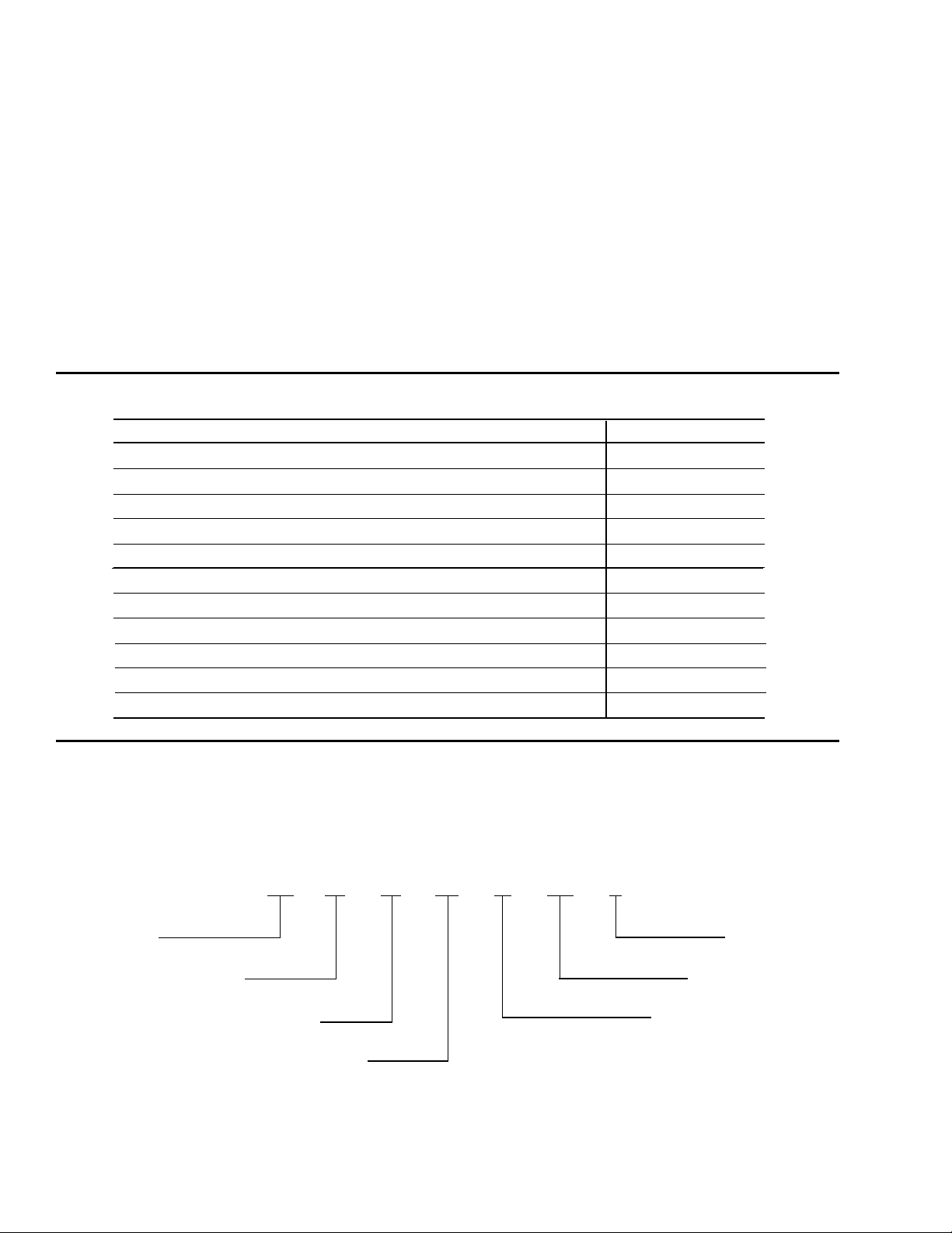
NOMENCLATURE
The model number denotes the following characteristics of the unit
YT K3 C4 E2 — CR J
Model Design Level
Cooler Code Motor Code
Condenser Code Power Supply
— for 60 Hz
Compressor Code 5 for 50 Hz
4
YORK INTERNATIONAL
Page 5

FORM 160.55-O1 (604)
TABLE OF CONTENTS
SECTION 1 Description of System and Fundamentals of Operation............................... 7
SECTION 2 OptiView Control Center ............................................................................. 9
SECTION 3 Printers ..................................................................................................... 112
SECTION 4
SECTION 5
SECTION 6
SECTION 7
System Operating Procedures .................................................................. 124
System Components Description ............................................................. 131
Operational Maintenance ......................................................................... 135
Troubleshooting........................................................................................ 138
SECTION 8 Maintenance ............................................................................................. 144
SECTION 9 Preventive Maintenance ........................................................................... 152
SECTION 10 OptiSave Energy Analyser Feature .......................................................... 154
YORK INTERNATIONAL
5
Page 6

LIST OF FIGURES
FORM 160.55-O1 (604)
FIG. 1 – MODEL YT MILLENNIUM CHILLER.................... 7
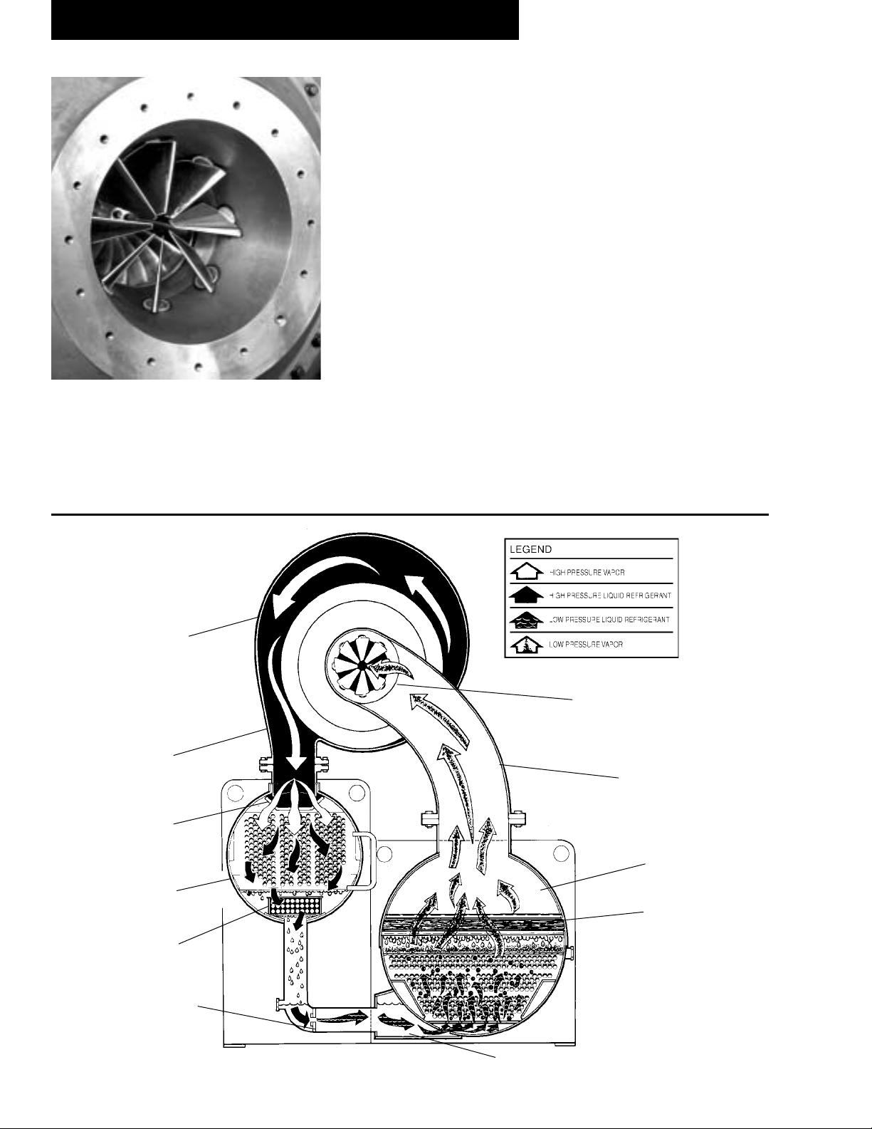
FIG. 2 – REFRIGERANT FLOW-THROUGH CHILLER..... 8
DETAIL A – COMPRESSOR PREROTATION
VANES.................................................................. 8
FIG. 3 – CONTROL CENTER .......................................... 12
FIG. 4 – HOME SCREEN................................................. 16
FIG. 5 – SYSTEM SCREEN............................................. 18
FIG. 6 – EVAPORATOR SCREEN...................................20
FIG. 7 – CONDENSER SCREEN..................................... 22
FIG. 8 – PURGE SCREEN............................................... 24
FIG. 9 – REFRIGERANT LEVEL CONTROL SCREEN...26
FIG. 10 – COMPRESSOR SCREEN.................................. 28
FIG. 11 – HOT GAS BYPASS SCREEN............................ 30
FIG. 12 – SURGE PROTECTION SCREEN ...................... 32
FIG. 13 – PRE-ROTATION VANES CALIBRATION
SCREEN............................................................. 36
FIG. 14 – VSD TUNING SCREEN ..................................... 38
FIG. 15 – OIL SUMP SCREEN........................................... 40
FIG. 16 – ELECTRO-MECHANICAL STARTER SCREEN 41
FIG. 17 – SOLID STATE STARTER
(MOD A) SCREEN.............................................. 42
FIG. 18 – SOLID STATE STARTER
(MOD B) SCREEN ............................................. 44
FIG. 19 – VARIABLE SPEED DRIVE SCREEN................. 46
FIG. 20 – VARIABLE SPEED DRIVE DETAILS SCREEN
(All VSD except Part Number 371-02767-XXX
(60 Hz) or 371-03700-XXX (50 Hz))................... 48
FIG. 21 – VARIABLE SPEED DRIVE DETAILS SCREEN
(VSD with Part Number 371-02767-XXX
(60 Hz) or 371-03700-XXX (50 Hz))................... 50
FIG. 22 – ADAPTIVE CAPACITY CONTROL DETAILS
SCREEN............................................................. 52
FIG. 23 – HARMONIC FILTER DETAILS SCREEN
(All VSD except Part Number 371-02767-XXX
(60 Hz) or 371-03700-XXX (50 Hz))................... 54
FIG. 24 – HARMONIC FILTER DETAILS SCREEN
(VSD with Part Number 371-02767-XXX (60 Hz)
or 371-03700-XXX (50 Hz))................................ 56
FIG. 25 – SETPOINTS SCREEN ....................................... 58
FIG. 26 – SETUP SCREEN................................................ 60
FIG. 27 – SCHEDULE SCREEN........................................64
FIG. 28 – USER SCREEN.................................................. 66
FIG. 29 – COMMS SCREEN.............................................. 68
FIG. 30 – PRINTER SCREEN............................................ 70
FIG. 31 – SALES ORDER SCREEN..................................72
FIG. 32 – OPERATIONS SCREEN....................................74
FIG. 33 – HISTORY SCREEN............................................ 76
FIG. 34 – HISTORY DETAILS SCREEN............................ 78
FIG. 35 – SECURITY LOG SCREEN................................. 79
FIG. 36 – SECURITY LOG DETAILS SCREEN................. 80
FIG. 37 – TREND SCREEN ............................................... 82
FIG. 38 – TREND SETUP SCREEN .................................. 84
FIG. 39 – ADVANCED TREND SETUP SCREEN.............. 86
FIG. 40 – COMMON SLOTS SCREEN..............................88
FIG. 41 – CUSTOM VIEW SCREEN.................................. 89
FIG. 42 – CUSTOM VIEW SETUP SCREEN..................... 90
FIG. 43 – PRINTERS ........................................................112
FIG. 44 – SAMPLE PRINTOUT (STATUS)........................116
FIG. 45 – SAMPLE PRINTOUT (SETPOINTS).................110
FIG. 46 – SAMPLE PRINTOUT (SCHEDULE)..................119
FIG. 47 – SAMPLE PRINTOUT (SALES ORDER)........... 120
FIG. 48 – SAMPLE PRINTOUT (HISTORY) .................... 121
FIG. 49 – SAMPLE PRINTOUT (SECURITY LOG).......... 122
FIG. 50 – SAMPLE PRINTOUT (TREND)........................ 123
FIG. 51 – SAMPLE PRINTOUT
(CUSTOM SCREEN REPORT)........................ 123
FIG. 52 – SAMPLE PRINTOUT
(ADAPTIVE CAPACITY CONTROL NEW MAP
POINT REPORT) ............................................ 123
FIG. 53 – SAMPLE PRINTOUT
(ADAPTIVE CAPACITY CONTROL EXISTING
MAP POINTS REPORT)..................................123
FIG. 54 – OPERATION SEQUENCE & TIMING
DIAGRAM (ELECTRO-MECHANICAL
& SOLID STATE STARTER APPLICATIONS).. 126
FIG. 55 – OPERATION SEQUENCE & TIMING
DIAGRAM (COMPRESSOR MOTOR
VARIABLE SPEED DRIVE APPLICATIONS)... 126
FIG. 56 – MINIMUM ENTERING CONDENSING
WATER TEMPERATURE................................. 127
FIG. 57 – LIQUID CHILLER LOG SHEETS ..................... 127
FIG. 58 – TURBOGUARD PURGE UNIT......................... 129
FIG. 59 – SCHEMATIC DRAWING (YT) COMPRESSOR
LUBRICATION SYSTEM.................................. 132
FIG. 60 – OIL RETURN SYSTEM....................................135
FIG. 61 – ASSEMBLY OF DEHYDRATOR....................... 136
FIG. 62 – CHARGING OIL RESERVOIR WITH OIL ........ 137
FIG. 63 – EVACUATION OF CHILLER............................145
FIG. 64 – SATURATION CURVE ..................................... 147
FIG. 65 – DIAGRAM - MEGGING MOTOR WINDINGS .. 149
FIG. 66 – MOTOR STATOR TEMPERATURE &
INSULATION RESISTANCES.......................... 150
6
YORK INTERNATIONAL
Page 7

FORM 160.55-O1 (604)
SECTION 1
DESCRIPTION OF SYSTEM AND FUNDAMENTALS OF OPERATION
COMPRESSOR
PURGE
UNIT
CONDENSER
CONTROL
CENTER
MOTOR
1
29509A
FIG. 1 – MODEL YT MILLENNIUM CHILLER
SYSTEM OPERATION DESCRIPTION (SEE FIG. 2)
The YORK Model YT Millennium Chiller is commonly
ap plied to large air conditioning systems, but may be
used on other applications. The chiller consists of an
open motor mounted to a compressor (with integral
speed in creas ing gears) condenser, cooler and vari able
ß ow con trol.
The chiller is controlled by a modern state of the art
OptiView Control Center that monitors its op er a tion. The
Control Center is programmed by the op er a tor to suit job
speciÞ cations. Automatic timed start-ups and shut downs
are also programmable to suit night time, week ends and
holidays. The operating status, tem per a tures, pressures
and other information per ti nent to op er a tion of the chiller
are automatically dis played and read on a graphic message display. Other displays can be ob served by press ing
the keys as labeled on the Con trol Center. The chill er
with the OptiView Control Cen ter is applied with an
electro-mechanical start er, YORK Solid State Start er
(optional) or Variable Speed Drive (optional).
There could be either of two different Solid State Start ers applied. New production chillers are equipped with
the Mod “B” Solid State Starter. This starter contains a
COOLER
combination Logic/Trigger Board that interfaces the
Con trol Center with a serial communications link. Ear li er vintage chillers, such as those encountered in Con trol
Cen ter retroÞ t ap pli ca tions are equipped with the Mod
“A” starter. This Start er con tains a Trig ger Board that
in ter fac es to a Logic Board that is in stalled inside of the
Control Cen ter.
In operation, a liquid (water or brine to be chilled) ß ows
through the cooler, where boiling refrigerant absorbs heat
from the liquid. The chilled liquid is then piped to fan
coil units or other air conditioning terminal units, where
it ß ows through Þ nned coils, absorbing heat from the
air. The warmed liquid is then returned to the chiller to
complete the chilled liquid circuit.
The refrigerant vapor, which is produced by the boil ing
action in the cooler, ß ows to the compressor where the
rotating impeller increases its pressure and tem per a ture
and discharges it into the condenser. Water ß ow ing
through the condenser tubes absorbs heat from the re frig er ant va por, causing it to condense. The con dens er water
is sup plied to the chiller from an external source, usually
a cool ing tower. The condensed re frig er ant drains from
the con dens er into the liquid return line, where the vari-
YORK INTERNATIONAL
7
Page 8
Description of System and Fun da men tals of Operation
able oriÞ ce meters the ß ow of liquid re frig er ant to the
cooler to com plete the refrigerant cir cuit.
The major components of a chiller are selected to han dle
the refrigerant, which would be evaporated at full load
design conditions. However, most systems will be called
upon to deliver full load capacity for only a relatively
small part of the time the unit is in operation.
CAPACITY CONTROL
The major components of a chiller are selected for full
load capacities, therefore capacity must be controlled
to maintain a constant chilled liquid temperature leav ing the cooler. Prerotation vanes (PRV), located at the
en trance to the compressor impeller, compensate for
vari a tion in load (See Fig. 2, Detail A).
FORM 160.55-O1 (604)
7619A(D)
DETAIL A – COMPRESSOR PREROTATION VANES
COMPRESSOR
DISCHARGE
The position of these vanes is automatically controlled
through a lever arm attached to an electric motor lo cat ed
outside the compressor housing. The automatic adjustment of the vane position in effect provides the performance of many different compressors to match various
load conditions from full load with vanes wide open to
minimum load with vanes completely closed.
PREROTATION VANES
(See Detail A)
SUCTION
DISCHARGE
BAFFLE
CON-
SUB-COOL-
FLOW CON TROL
FIG. 2 – REFRIGERANT FLOW-THRU CHILL ER
8
COOLER
ELIMINATOR
LD00924
OIL COOLER
YORK INTERNATIONAL
Page 9

SECTION 2
OPTIVIEW CONTROL CEN TER
INTRODUCTION
FORM 160.55-O1 (604)
The YORK OptiView Control Center is a mi cro pro ces sor based control system for R-11 or R123 cen trif u gal
chillers. It controls the leaving chilled liq uid tem per a ture
via pre-rotation vane controls and has the abil i ty to limit
motor current via control of the pre-ro ta tion vanes. It is
com pat i ble with YORK Sol id State Start er (optional),
Variable Speed Drive (op tion al) and Electro-Mechanical
starter ap pli ca tions.
The panel comes conÞ gured with a full screen LCD
Graphic Display mounted in the middle of a keypad
in ter face. The graphic display allows the presentation
of several operating parameters at once. In addition,
the operator may view a graphical representation of the
his tor i cal operation of the chiller as well as the present
operation. For the novice user, the locations of various
chiller parameters are clearly and intuitively marked.
Instructions for speciÞ c operations are provided on
many of the screens.
The graphic display also allows information to be rep re sent ed in both English (temperatures in °F and pres sures
in PSIA) and Metric (temperatures in °C and pres sures in
kPa) mode. The advantages are most ap par ent, however,
in the ability to display many languages.
The Control Center continually monitors the system operation and records the cause of any shutdowns (Safe ty,
Cycling or Normal). This information is re cord ed in
memory and is preserved even through a pow er fail ure
condition. The user may recall it for view ing at any
time. During operation, the user is con tin u al ly advised
of the operating conditions by various sta tus and warn ing
messages. In addition, it may be con Þ g ured to notify the
user of certain con di tions via alarms. A complete listing
of shutdown, status and warning messages is at tached in
the Display Messages section of this book.
There are certain screens, displayed values, pro gram ma ble Setpoints and manual control shown in this book
that are for Service Technician use only. They are only
displayed when logged in at SERVICE access level
or higher. The Setpoints and pa ram e ters displayed on
these screens are explained in detail in YORK Service
Man u al 160.55-M1. These parameters affect chiller
op er a tion and should NEVER be modifi ed by anyone
oth er than a qualifi ed Service Technician. They are
shown in this book for reference only.
Advanced Diagnostics and troubleshooting in for ma tion
for Service Technicians are included in YORK Service
Manual 160.55-M1. Also included in the Service man u al are detailed descriptions of chiller features, such as
the Refrigerant Level Control (Future), Purge sys tem,
Hot Gas By pass, Remote Setpoints and Smart Freeze
Pro tec tion.
The control center expands the capabilities of re mote
control and communications. By providing a com mon
networking protocol through the ISN GPIC YORK
Chill ers not only work well in di vid u al ly, but also as
a team. This new protocol allows in creased remote
con trol of the chiller, as well as 24-hour performance
mon i tor ing via a remote site. In ad di tion, compatibility
is main tained with the present net work of ISN com mu ni ca tions. The chiller also main tains the standard digital
remote ca pa bil i ties as well. Both of these remote con trol
capabilities allow for the standard Energy Man age ment
System (EMS) in ter face:
1. Remote Start
2. Remote Stop
3. Remote Leaving Chilled Liquid Temperature
Setpoint adjustment (0-20mA or 4-20mA, 0-10VDC
or 2-10VDC) or Pulse Width Modulation
4. Remote Current Limit Setpoint adjustment (0-20mA
or 4-20mA, 0-10VDC or 2-10VDC) or Pulse Width
Mod u la tion
5. Remote “Ready to Start” Contacts
6. Safety Shutdown Contacts
7. Cycling Shutdown Contacts
The chiller operating program resides in the Optiview
control center Microboard. The control center could be
equipped with either of the following Microboards:
• 031-01730-000 – shipped in new production chillers until September 2003. The program resides in
a replaceable Flash Memory Card. The software
version (C.MLM.02.xx.yzz) is printed on label
adhered to card. Program can be upgraded by
replacing the card.
• 031-02430-000 – shipped in new production chillers after September 2003. The program resides in
non-removable onboard memory. The software
2
YORK INTERNATIONAL
9
Page 10

Description of System and Fun da men tals of Operation
FORM 160.55-O1 (604)
version is C.OPT.02.xx.yzz, and is viewable on
the DIAGNOSTICS Screen in SERVICE access
level. The program can be upgraded by downloading a new program from a Program Card. Program
Cards are shirt-pocket-size portable memory storage devices available from YORK.
Earlier vintage chillers could be equipped with a later
Microboard due to service replacement.
Software versions (C.MLM.02.xx.yzz or
C.OPT.02.xx.yzz) are alpha-numeric codes that represent the application, language package and revision
levels per below. Each time the controls portion or language section is revised, the respective revision level
increments.
• C – Commercial chiller
• MLM – Used on Microboard 031-01730000
• OPT - Used on Microboard 031-02430000
• 02 – YT chiller
• xx - controls revision level (00, 01, etc)
• y – language package (0=English only,
1=NEMA, 2=CE, 3=NEMA/CE )
• zz – language package revision level (00,
01, etc)
Throughout this book, reference is made to functions and
features that are only available in certain Flash Memory
Card revision levels (C.MLM.02.xx.xxx). To cross reference C.MLM software to C.OPT software, refer to the
controls revision level. Software version
C.OPT.02.04B.xxx is of the same controls revision
level as C.MLM.02.04.xxx. From this starting point,
both receive the same updates at each revision. Software upgrades should only be performed by a Service
Technician.
10
YORK INTERNATIONAL
Page 11

FORM 160.55-O1 (604)
THIS PAGE INTENTIONALLY LEFT BLANK
TO MAINTAIN FORMAT
YORK INTERNATIONAL
11
Page 12
OptiView Control Center
FORM 160.55-O1 (604)
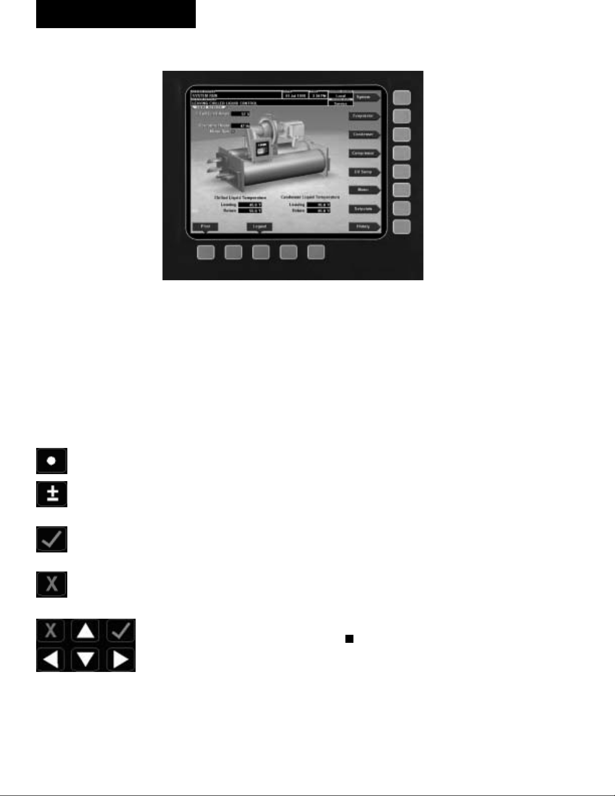
CONTROL CENTER
FIG. 3
The OptiView Control Center display is high light ed by a
full screen graph ics display. This dis play is nested with in
a stan dard keypad and is sur round ed by “soft” keys
which are re de Þ ned based on the currently dis played
screen. Eight buttons are avail able on the right side of the
pan el and are primarily used for navigation between the
sys tem screens. At the base of the display are 5 ad di tion al
but tons. The area to the right of the key pad is used for
data entry with a stan dard numeric key pad provided for
en try of system setpoints and lim its.
The Decimal key provides accurate entry of
setpoint values.
A +/- key has also been provided to allow en try
of neg a tive values and AM/PM selection dur ing
time entry.
In order to accept changes made to the chiller
setpoints, the Check key is provided as a uni-
ver sal ‘En ter’ key or ‘Accept’’ symbol.
In order to reject entry of a setpoint or dismiss
an entry form, the ‘X’ key is provided as a uni-
ver sal ‘Can cel’ sym bol.
Cursor Arrow keys are pro-
vid ed to allow move ment on
screens which contain a large
amount of entry data. In ad di tion, these keys can be used
to scroll through his to ry and
event logs.
The Start/Stop control is op er at ed via a three-position
rocker switch. When toggled all the way to the right, it is
considered in the STOP/RESET position. When in the
00134VIP
middle position, this is considered the RUN state. When
toggled to the left-most position, it is considered in the
START state. Each state is described in detail below:
• STOP / RESET (O)
When in this position, the chiller will not run un der
any condition. For safe ty reasons, this po si tion is
re quired for many maintenance tasks to be com plet ed
(such as prox im i ty probe and vane cal i bra tion). In
ad di tion, the switch must be placed in this state
fol low ing a Safety shut down before the chill er is
al lowed to re start. This guar an tees that manual in ter ven tion has tak en place and the shut down has been
ac knowl edged.
• START (◄)
The switch can only remain in this po si tion when
being acted upon by a man u al force. Once the user
has re leased the switch, it au to mat i cal ly re verts to
the RUN po si tion. Gen er al ly, this state only occurs
mo men tari ly as the operator at tempts to locally start
the unit. Once this po si tion has been sensed, if all
fault con di tions are cleared, the unit will en ter the
sys tem prelube (start se quence).
• RUN ( )
When in this position, the chiller is able to op er ate.
The switch spring-re turns to this state after it has
been tog gled to the START po si tion. When in this
state, the chiller is al lowed to function normally and
will also al low the chill er to au to mat i cal ly re start fol low ing a Cy cling shut down. The switch must be in
this state to re ceive a val id re mote start signal when
op er at ing under a re mote con trol source.
12
YORK INTERNATIONAL
Page 13

INTERFACE CONVENTIONS
FORM 160.55-O1 (604)
OVERVIEW
The new graphical display on each control pan el al lows
a wide variety of information to be pre sent ed to the
user. Each screen description in this document will be gin
with a section entitled Overview which will de scribe
the graphical elements on the screen and give a short
summary of the functions available. Each el e ment on
the screen will then be categorized into three dis tinct
groups: Display Only, Programmable and Nav i ga tion.
Below is a short description of what types of in for ma tion
are included in these groups.
The Programmable values and Navigation commands
are also subject to access level restrictions as de scribed
below. For each of these elements, an in di ca tion is giv en
to show the minimum access level required to program
the value or navigate to the subscreen.
DISPLAY ONLY
Values in this group are read-only parameters of in for ma tion about the chiller operation. This type of in for ma tion may be represented by a numerical value, a text
string or an LED image. For numerical values, if the
monitored parameter is above the normal operating
range, the high limit value will be displayed along with
the ‘>’ symbol; if it is below the normal operating range,
the low limit value will be displayed along with the
‘<’ sym bol. In some cases, the value may be rendered
in valid by other conditions and the display will use X’s
to in di cate this.
PROGRAMMABLE
Values in this group are available for change by the user.
In order to program any setpoints on the sys tem, the user
must Þ rst be logged in with the ap pro pri ate access level.
Each of the programmable values re quires a spe ciÞ c Ac-
cess Level which will be indicated beside the speciÞ ed
value. All of the pro gram ma ble controls in the system
fall into one of the categories described below:
Access Level
In order to program any setpoints on the sys tem, the user
must Þ rst login with an appropriate ac cess level. When
power is applied to the chiller, the system begins with an
Access Level of VIEW. This will allow the user to navi-
gate to most screens and observe the values displayed
there. However, the user will not be allowed to change
any values. To change any values, the user must return to
the Home Scr een (shown by de fault when pow er is ap-
plied to the system) and use the LO G IN but ton or uti lize
the CHANGE SETPOINTS key de scribed be low. At
this point, the user will be prompt ed to enter a User ID
and the corresponding Password. By default, the User
ID is zero (0). In order to gain stan dard OP ER A TOR
level access, the Pass word would be en tered as 9 6 7 5,
us ing the numeric keypad. OP ER A TOR ac cess reverts
to the VIEW lev el after 10 con tin u ous min utes without
a keypress. If a custom User ID and Pass word have been
deÞ ned (see User Screen ), the user may enter that User
ID and the cor re spond ing Password value.
If the correct password is received, the user is au tho rized with the appropriate Access Level. If an incorrect
pass word is entered, the user is notiÞ ed of the failure
and prompted again. At this point the user may retry the
password entry or cancel the login attempt.
Change Setpoints
On screens containing setpoints programmable at the
OPERATOR access level, a key with this label will be
visible if the present access level is VIEW. This key
brings up the Access Level prompt described above. It
allows the user to login at a higher Access Level with out
returning to the Home Screen. After login, the user may
then modify setpoints on that screen.
Setpoints
The control center uses the setpoint values to control the
chiller and other devices connected to the chiller system.
Setpoints can fall into several categories. They could be
numeric values (such as 45.0°F for the Leav ing Chilled
Liquid Temperature) or they could Enable or Disable a
feature or function.
Regardless of which setpoint is being programmed, the
following procedure applies:
1. Press the desired setpoint key. A dialog box ap pears
dis play ing the present value, the up per and low er
limits of the programmable range and the de fault
value.
2. If the dialog box begins with the word “ENTER”,
use the numeric keys to enter the desired value.
2
YORK INTERNATIONAL
13
Page 14

OptiView Control Center
FORM 160.55-O1 (604)
Lead ing zeroes are not necessary. If a dec i mal point
is nec es sary, press the ‘•’ key (i.e. 45.0).
Pressing the ▲ key, sets the entry value to the de fault
for that setpoint. Pressing the ▼ key, clears the present entry. The ◄ key is a backspace key and causes
the entry point to move back one space.
If the dialog box begins with “SELECT”, use the
◄ and ► keys to select the desired value.
If the previously deÞ ned setpoint is de sired, press
the ‘X’ (Cancel) key to dismiss the di a log box.
3. Press the ‘!’ (Enter) key.
If the value is within range, it is accepted and the
dialog box disappears. The chiller will be gin to op er ate based on the new programmed value. If out of
range, the val ue will not be ac cept ed and the user is
prompt ed to try again.
Manual Controls
Some keys are used to perform manual control func tions. These may involve manual control of items such
as the pre-rotation vanes, variable oriÞ ce (future) or
hot gas bypass valve. Other keys in this category are
used to ini tiate/ter mi nate processes such as cal i bra tions
or re ports.
Home Screen (page 14)
System Screen (page 16)
Evaporator (page 18)
Condenser (page 20)
Purge (page 22)
Refrig. Level Control (page 24)
Compressor (page 26)
Hot Gas Bypass (page 28)
Surge Protection Screen (page 30)
Vane Calibration (page 32)
VSD Tuning (page 34)
Oil Sump (page 36)
Motor (page 37)
EM Starter Version (page 37)
Mod “A” Solid State Starter (page 38)
Mod “B” Solid State Starter (page 40)
VSD Version (page 42)
VSD Details (page 44)
Free Cursor
On screens containing many setpoints, a speciÞ c “soft”
key may not be assigned to each setpoint value. A soft
key will be assigned to enable the cursor arrow keys
below the numeric keypad which are used to “high light”
the desired setpoint Þ eld. At this point, the ‘!’ key is
pressed to bring up a dialog prompting the user to enter
a new setpoint value. The ‘X’ key cancels cursor mode.
(See the Schedule Screen [Fig. 24] for an example.)
NAVIGATION
In order to maximize the amount of values which the
panel can display to the user and in order to place those
values in context, multiple screens have been de signed to
describe the chiller operation. In order to move from one
screen to the next, navigation keys have been de Þ ned.
These keys allow the user to either move “for ward” to
a subscreen of the present screen or move “back ward”
to the previous screen. Except for the Home Screen
dis play, the upper-right “soft” key will always return
the user to the Home Screen. Navigating with “soft”
keys is as simple as pressing the key next to the label
con tain ing the name of the desired screen. The system
will im me di ate ly refresh the display with the graph ics
for that screen. Following is a layout of all the screens
and how they are connected.
ACC Details (page 48)
Harmonic Filter Details (page 50)
Setpoints (page 54)
Setup (page 56)
Schedule (page 58)
User (page 60)
Comms (page 62)
Printer (page 64)
Sales Order (page 66)
Operations (page 68)
Diagnostics (Refer to YORK
Service Man u al 160.55-M1)
History (page 70)
History Details (page 72)
Security Log (page 73)
Security Log Details (page 74)
Trend (page 76)
Trend Setup (page 78)
Advanced Trend Setup (page 80)
Common Slots (page 82)
Custom View (page 83)
Custom Setup (page 84)
14
YORK INTERNATIONAL
Page 15

FORM 160.55-O1 (604)
LANGUAGES
are available. English is the default language. If a language
other than English is being displayed, an English-only speak-
The Screens can be displayed in various languages. Lan guage selection is done on the USER Screen. The desired
language is selected from those avail able. Not all lan guag es
ing person should nav i gate to the USER Screen using the
preceding Navigation chart and select English per the USER
Screen in struc tions in this book.
ANALOG INPUT RANGES
The following table indicates the valid display range for each of the analog input values. In the event that the input
sensor is reading a value outside of these ranges, the < or > symbols will be displayed beside the min i mum or maximum value, respectively.
LOW HIGH UNITS LOW HIGH UNITS
Leaving Chilled Liquid Temperature 0.0 82.0 °F -17.7 27.7 °C
Return Chilled Liquid Temperature 0.0 94.1 °F -17.7 34.5 °C
Leaving Condenser Liquid Temperature 8.0 133.5 °F -13.3 56.3 °C
Return Condenser Liquid Temperature 8.0 133.5 °F -13.3 56.3 °C
Evaporator Refrigerant Temperature 0.0 126.1 °F -17.7 52.3 °C
Discharge Temperature 19.0 226.3 °F -7.2 107.9 °C
Oil Temperature 19.0 226.3 °F -7.2 107.9 °C
Condenser Pressure 2.5 35.3 PSIA 17.2 243.4 KPAA
Condenser Temperature (R11)* -1.4 124.2 °F -18.5 51.2 °C
Condenser Temperature (R123)* 7.2 130.1 °F -13.7 54.5 °C
Evaporator Pressure 0.0 12.5 PSIA 6.9 86.2 KPAA
Evaporator Temperature (R11)* -31.2 66.8 °F -35.7 19.3 °C
Evaporator Temperature (R123)* -22.4 74.2 °F -30.2 23.4 °C
Oil Sump Pressure 2.9 20.9 PSIA 20.0 144.1 KPAA
Oil Pump Pressure 14.3 78.2 PSIA 98.6 539.2 KPAA
Purge Pressure 0.0 100.0 PSIA 6.9 689.5 KPAA
Refrigerant Level (Future) 0.0 100.0 % 0.0 100.0 %
Drop Leg Refrigerant Temperature 0.0 121.8 °F -17.7 49.8 °C
*Saturation temperatures are calculated values. They will dis play XXX if the pressure used for the calculation is out of range.
ANALOG INPUT
ENGLISH RANGE METRIC RANGE
2
YORK INTERNATIONAL
15
Page 16

OptiView Control Center
FORM 160.55-O1 (604)
HOME SCREEN
FIG. 4
OVERVIEW
When the chiller system is powered on, the above de fault display appears. The primary values which must
be monitored and controlled are shown on this screen.
The Home Screen display depicts a visual rep re sen ta tion
of the chiller itself. Animation indicates chilled liq uid
ß ow.
DISPLAY ONLY
Chilled Liquid Temperature - Leaving
Displays the temperature of the liquid as it leaves the
evaporator.
Chilled Liquid Temperature - Return
Displays the temperature of the liquid as it enters the
evaporator.
Condenser Liquid Temperature - Leaving
Displays the temperature of the liquid as it leaves the
condenser.
Condenser Liquid Temperature - Return
Displays the temperature of the liquid as it enters the
condenser.
Motor Run (LED)
Is ON when the digital output controlling the Motor
Start er contact is on.
00347VIP
Input Power (kW)
Available only if the chiller system is utilizing a Vari able Speed Drive motor controller or Mod “B” Solid
State Start er. This dis plays the total in put power used
by the sys tem.
% Full Load Amps
This displays the percentage of full load amps utilized
by the system.
Operating Hours
Displays the cumulative operating hours of the chiller.
PROGRAMMABLE
Login
Access Level Re quired: VIEW
The Control Center restricts certain op er a tions based
on password entry by the operator. Three dif fer ent ac-
cess lev els are provided as follows: VIEW
: The panel
de faults to the low est access level which is termed
VIEW. In this mode, the chiller op er at ing val ues and
setpoints can be ob served, but no changes can be made.
OP ER A TOR: The second ac cess level is termed OP-
ER A TOR and will allow the cus tom er to change all
of the setpoints re quired to op er ate the chill er system.
The OP ER A TOR access level reverts to the VIEW
lev el af ter 10 continuous minutes without a keypress.
SER VICE: In the event that advanced di ag nos tics are
nec es sary, a SER VICE ac cess level has been pro vid ed.
16
YORK INTERNATIONAL
Page 17

FORM 160.55-O1 (604)
Only qual i Þ ed service personnel utilize this access lev el.
This lev el provides advanced control over many of the
chiller func tions and allows cal i bra tion of many of the
chiller con trols. The access lev els are listed above in
hierarchical order be gin ning with the lowest level and
proceeding to the high est level. Users logged in under
higher access levels may perform any actions per mit ted
by lower access levels.
The OPERATOR access level is ac com pa nied by a
10-minute timeout. After ten (10) suc ces sive minutes
with out a keypress, the panel will re vert to the VIEW
ac cess level. This prevents un au tho rized changes to the
chiller if a user was logged in at a higher access level
and failed to logout. Proper pro ce dure requires that af ter
making necessary setpoint ad just ments the user re turn
to the Home Screen and logout.
Logout
Access Level Required: OP ER A TOR
This key is displayed when a user is logged in at any
level other than VIEW. Pressing it will return the ac cess
level to VIEW.
Print
Access Level Required: VIEW
Use this key to generate a hard-copy report of the present
system status. This provides a snapshot of the primary
operating conditions at the time the key is pressed. The
History page provides enhanced reporting ca pa bil i ty.
(See HISTORY below.) This option will not be present
if the chill er is pres ent ly conÞ gured to log any in com ing
Adap tive Ca pac i ty Con trol map points. (See the Adap tive Capacity Control Details screen.)
Message Clear
Access Level Required: SER VICE
When certain safety or cycling conditions have been
detected and the chiller has been shutdown, the main
status display of the chiller will continue to display a
message indicating the cause of the shutdown. Using
this key, the message can be cleared once the condition
has been removed.
Warning Reset
NAVIGATION
System
Used to provide additional system information.
Evaporator
A detailed view of all evaporator parameters, in clud ing
the programmable Leaving Chilled Liq uid Setpoints.
Condenser
A detailed view of all condenser parameters, in clud ing
control of the purge functions.
Compressor
A detailed view of all the compressor pa ram e ters. This
includes pre-rotation vane control, Hot Gas Bypass
Control and PRV cal i bra tion.
Oil Sump
A detailed view of all the oil pump and oil sump pa ram e ters.
Motor
A detailed view of the motor controller pa ram e ters, spe ciÞ c to the controller type presently utilized on the chill er
system. This allows programming of the Cur rent Limit
and the Pulldown Demand Lim it values. For a VSD
system, the Adaptive Capacity Control and Har mon ic
Filter information is con trolled under this screen.
Setpoints
This screen provides a single location to pro gram the
most common system setpoints. It is also the gateway
to many of the general system setup pa ram e ters such as
Date/Time, Display Units, Sched ul ing, Printer Setup,
etc.
History
This screen provides access to a snapshot of system data
at each of the last 10 shutdown con di tions.
2
Access Level Re quired: OP ER A TOR
Use of this key acknowledges a warning condition and
resets the message display associated with it.
YORK INTERNATIONAL
17
Page 18

OptiView Control Center
FORM 160.55-O1 (604)
SYSTEM SCREEN
FIG. 5
OVERVIEW
This screen gives a general overview of common chill er
parameters for both shells.
DISPLAY ONLY
Discharge Temperature
Displays the temperature of the refrigerant in its gas eous state at discharge of the compressor as it travels
to the condenser.
Chilled Liquid Temperature - Leaving
Displays the temperature of the liquid as it leaves the
evaporator.
Chilled Liquid Temperature - Return
Displays the temperature of the liquid as it enters the
evaporator.
Chilled Liquid Temperature - Setpoint
Displays the active temperature setpoint to which the
chiller is controlling the evaporator liquid. This value
could come from a 0-20mA or 4-20mA, 0-10VDC or 210VDC input in An a log Remote mode, PWM signal in
Digital Remote mode, MicroGateway interface in ISN
mode or a locally pro grammed value in local mode.
Evaporator Pressure
Displays the present refrigerant pressure in the evap o ra tor.
00348VIP
Evaporator Saturation Temperature
Displays the present saturation temperature in the
evap o ra tor.
Condenser Liquid Temperature - Leaving
Displays the temperature of the liquid as it leaves the
condenser.
Condenser Liquid Temperature - Return
Displays the temperature of the liquid as it enters the
condenser.
Condenser Pressure
Displays the refrigerant pressure in the condenser.
Condenser Saturation Temperature
Displays the saturation temperature in the condenser.
Oil Sump Temperature
Displays the temperature of the oil in the sump.
Oil Pressure
Displays the pressure differential between the pump oil
pressure transducer and the sump oil pressure trans duc er.
If either of the transducers used to cal cu late this dif fer en tial is out of range, the display Þ eld will show XX.X.
% Full Load Amps
This displays the percentage of full load amps utilized
by the system.
18
YORK INTERNATIONAL
Page 19

FORM 160.55-O1 (604)
Current Limit
Displays the current limit value in use. This value could
come from a 0-20mA or 4-20mA, 0-10VDC or 2-10VDC
input in An a log Remote mode, PWM signal in Digital
Remote mode, MicroGateway interface in ISN mode or
a locally pro grammed value.
PROGRAMMABLE
None
NAVIGATION
Home
Access Level Re quired: VIEW
Causes an instant return to the Home Screen.
2
YORK INTERNATIONAL
19
Page 20
OptiView Control Center
FORM 160.55-O1 (604)
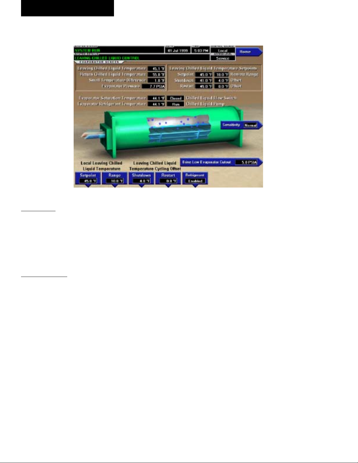
EVAPORATOR SCREEN
FIG. 6
OVERVIEW
This screen displays a cutaway view of the chiller evap o ra tor. All setpoints relating to the evaporator side of
the chiller are maintained on this screen. Animation of
the evaporation process indicates whether the chill er is
presently in a RUN condition. Animation of the liq uid
ß ow indicates chilled liquid ß ow.
DISPLAY ONLY
Chilled Liquid Flow Switch (Open / Closed)
Displays whether the liquid ß ow is present in the
evap o ra tor.
Chilled Liquid Pump
Displays the command presently sent by the control
center to the Chilled Liquid Pump (RUN or STOP).
Evaporator Pressure
Displays the present refrigerant pressure in the evap o ra tor.
Evaporator Saturation Temperature
Displays the present saturation temperature in the evap o ra tor.
Return Chilled Liquid Temperature
Displays the temperature of the liquid as it enters the
evaporator.
Leaving Chilled Liquid Temperature
Displays the temperature of the liquid as it leaves the
evaporator.
20
00349VIP
Evaporator Refrigerant Temperature
Displays the temperature of the refrigerant in the evap o ra tor, if the sensor is present.
Small Temperature Difference
Displays the difference between the Leaving Chilled
Liquid temperature and the Evaporator Refrigerant tem per a ture. The Evaporator Refrigerant temperature will be
represented by the Refrigerant Temperature sensor input
if the sensor is present, otherwise it will be rep re sent ed
by the Evaporator Saturation temperature.
Leaving Chilled Liquid Temperature Setpoints –
Setpoint
Displays the present setpoint to which the chiller is op er at ing, whether controlled locally or remotely.
Leaving Chilled Liquid Temperature Setpoints
– Shut down
Displays the Leaving Chilled Liquid Tem per a ture at which
the chiller will shut down to avoid over-cooling the build ing. By default this value is 4°F below the Leav ing Chilled
Setpoint.
Leaving Chilled Liquid Temperature Setpoints
– Restart
Displays the Leaving Chilled Liquid Tem per a ture at
which the chiller will restart after it has shut down due
to over-cooling temperature. By default, the chiller
will restart at the Leaving Chilled Liquid Tem per a ture
Setpoint.
YORK INTERNATIONAL
Page 21

FORM 160.55-O1 (604)
PROGRAMMABLE
Local Leaving Chilled Liquid Tem per a ture Range Access Level Re quired: OP ER A TOR
This is the range over which an analog (0-20mA or 420mA, 0-10VDC or 2-10VDC) in Analog Remote Mode
or a digital signal (PWM) in Digital remote mode can reset
the Leaving Chilled Liquid Temperature setpoint above
the operator programmed Base Setpoint (see be low).
Pro gram ma ble as ei ther 10°F or 20°F, with a de fault
of 20°F, it is added to the Base value to create a range
over which the re mote device can reset the setpoint. For
example, if this setpoint is pro grammed for 10°F and
the operator pro grammed value is 45°F, then the remote
device can set the Leav ing Chilled Liq uid Tem per a ture
setpoint over the range 45.0° - 55.0°F.
Local Leaving Chilled Liquid Temperature Setpoint
Access Level Re quired: OPERATOR
This value allows the user to deÞ ne the Leav ing Chilled
Liquid Temperature that is to be maintained by the chill er.
It is programmable over the range of 38.0°F to 70.0°F
(water) or 10.0°F to 70.0°F (brine). If Smart Freeze (see
below) is enabled, the range is 36.0°F to 70.0°F (water).
A remote device can provide an analog signal (0-20mA
or 4-20mA, 0-10VDC or 2-10VDC) in An a log Remote
mode or PWM signal in Digital Remote mode that chang es the setpoint by creating an offset above the operator
pro grammed Base Leaving Chilled Liquid Tem per a ture
setpoint. This offset may be de Þ ned up to 10.0°F or
20.0°F above the Base setpoint (see the Remote Leav ing
Chilled Liquid Temperature Setpoint Range de scrip tion
above). Additionally, a MicroGateway (in ISN Re mote
mode) can deÞ ne the setpoint through a serial data
stream. In this case, the in com ing setpoint is not an
off set that is applied to the locally programmed Base
setpoint value, but rath er is the setpoint value it self.
Leaving Chilled Liquid Temperature Cycling
Offset - Shutdown
Access Level Re quired: OP ER A TOR
This value allows the user to specify the Leaving Chilled
Liquid Temperature at which the chiller will shut down
on a LEAVING CHILLED LIQUID – LOW TEM-
PER A TURE cycling shutdown. This is done by de Þ n ing
an offset below the Leaving Chilled Liquid Tem per a ture
setpoint. It is programmable over a range of 1°F to 64°F
below the setpoint, to a minimum cutout of 36°F (water),
34°F (water with Smart Freeze enabled) or 6°F (brine). It
establishes the minimum allowable tem per a ture for the
Leaving Chilled Liquid Temperature and pre vents overcooling of the building. Anytime the Leaving Chilled
Liquid Temperature setpoint is in creased, the shut down
threshold is 36.0°F (water) or 6.0°F (brine) for the next
ten (10) minutes. If Smart Freeze (see be low) is enabled,
the threshold is 34.0°F for the next 10 minutes. After
ten (10) minutes have elapsed, the shut down thresh old
becomes the pro grammed setpoint val ue.
Leaving Chilled Liquid Temperature Cycling
Offset - Restart
Access Level Re quired: OP ER A TOR
This value allows the user to specify the Leaving Chilled
Liquid Temperature at which the chiller will restart
af ter a shutdown on a LEAVING CHILLED LIQ UID
– LOW TEMPERATURE cycling shutdown. This is
done by deÞ ning an offset above the Leaving Chilled
Liquid Temperature setpoint. It is pro gram ma ble over a
range of 0°F to 70°F above the setpoint, to a max i mum
restart value of 80°F. The chiller will au to mat i cal ly re start when this temperature is reached. This setpoint can
be used to reduce chiller cycling by de lay ing the chiller
restart until the cooling load has in creased.
Brine Low Evaporator Cutout
Ac cess Level Re quired: SERVICE
This value is only available in Brine mode. It allows
the user to specify the Evaporator Pressure at which a
safe ty shutdown is initiated. Service Technicians refer
to YORK Service Manual 160.55-M1.
Sensitivity
Access Level Re quired: SER VICE
This value allows the user to adjust the sen si tiv i ty of the
Leaving Chilled Liquid Temperature con trol. Service
Tech ni cians refer to YORK Service Manual 160.55M1.
Smart Freeze (Off / On)
Access Level Re quired: SER VICE
This value is only available if the chiller is not in Brine
mode. It allows the user to enable the Smart Freeze Point
Operation which allows the chiller to run closer to the
freeze point without shutting down. Service Tech ni cians
refer to YORK Service Manual 160.55-M1.
Refrigerant (Enabled / Disabled)
Access Level Re quired: SER VICE
When an Evaporator Refrigerant Sensor has been in stalled
it must be enabled via this toggle before the sys tem will
utilize the new, enhanced resolution input. Ser vice Tech ni cians refer to YORK Service Manual 160.55-M1.
NAVIGATION
Home
Access Level Re quired: VIEW
Causes an instant return to the Home Screen.
2
YORK INTERNATIONAL
21
Page 22
OptiView Control Center
FORM 160.55-O1 (604)
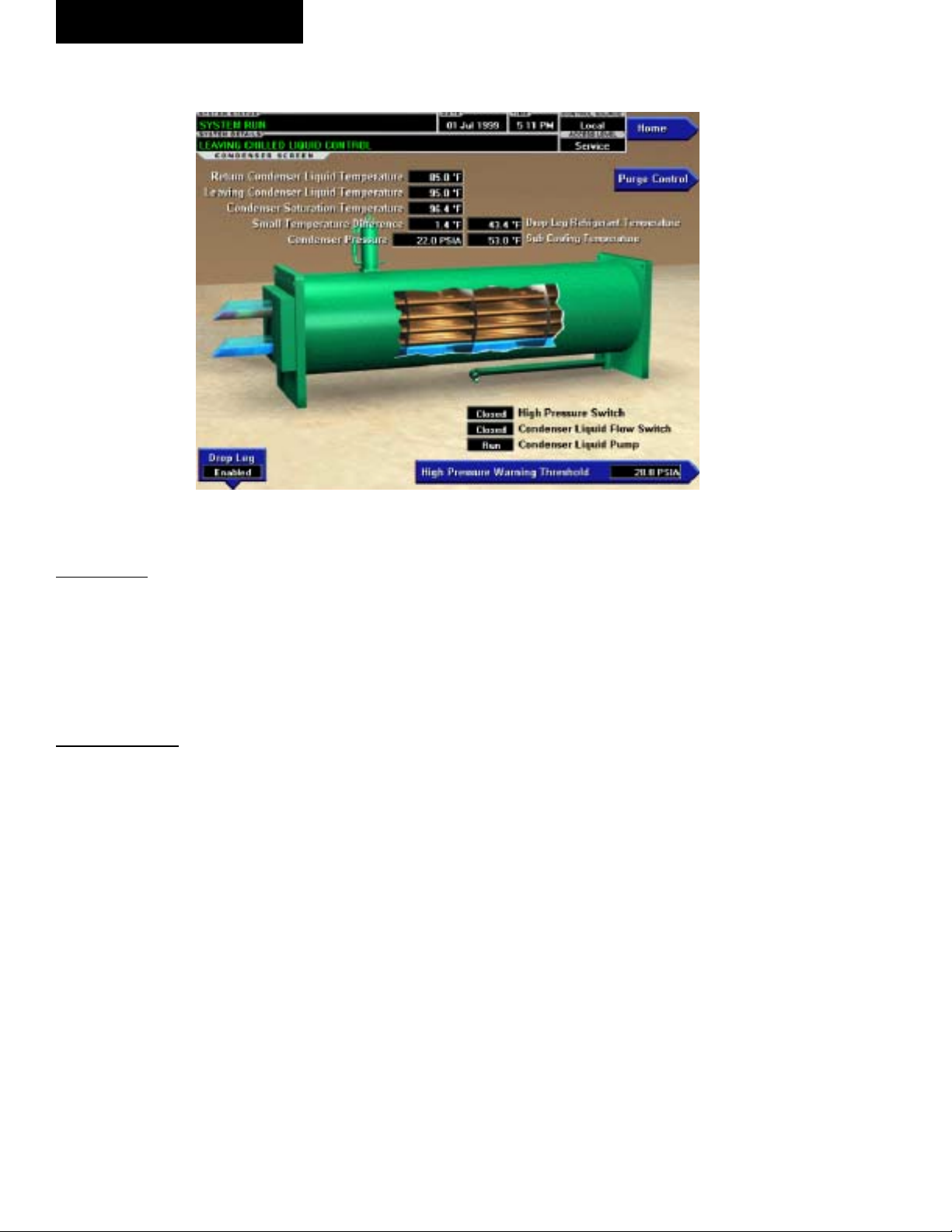
CONDENSER SCREEN
FIG. 7
OVERVIEW
This screen displays a cutaway view of the chiller
con dens er. All setpoints relating to the condenser side
of the chiller are maintained on this screen. Animation
indicates condenser liquid ß ow. This screen also serves
as a gateway to controlling the Refrigerant Level.
DISPLAY ONLY
Leaving Condenser Liquid Temperature
Displays the water temperature as it leaves the con dens er.
Return Condenser Liquid Temperature
Displays the water temperature as it enters the con dens er.
Condenser Pressure
Displays the refrigerant pressure in the condenser.
Condenser Saturation Temperature
Displays the saturation temperature in the condenser.
Small Temperature Difference
Displays the difference between the Condenser Re frig er ant temperature and the Leaving Condenser Liq uid
tem per a ture. The Condenser Refrigerant tem per a ture
will be represented by the Condenser Saturation tem per a ture.
00350VIP0
Drop Leg Refrigerant Temperature
Displays the temperature of the refrigerant in the drop
leg between the condenser and evaporator shells, if the
sensor is present.
Sub-Cooling Temperature
Displays the difference between the Condenser Re frig er ant temperature and the Drop Leg Refrigerant tem per a ture. The Condenser Refrigerant temperature will
be represented by the Condenser Saturation tem per a ture.
If the Drop Leg sensor is not present, this tem per a ture
is not displayed.
High Pressure Switch (Open / Closed)
Displays the present position of the high pressure switch.
This will indicate whether a High Pres sure fault is present.
Condenser Liquid Flow Switch
Indicates whether ß ow is present in the con dens er.
Condenser Liquid Pump (Run / Stop)
Indicates whether Condenser liquid pump is operating.
Refrigerant Level Position
Displays the present position of the refrigerant level if
this function is enabled.
22
YORK INTERNATIONAL
Page 23

FORM 160.55-O1 (604)
Refrigerant Level Setpoint
Displays the setpoint to which the refrigerant level is
being con trolled.
Ramp Up Time Remaining
Displays the time remaining in the period in which
the Re frig er ant Level Setpoint is being ramped to the
Re frig er ant Level Target Setpoint. This only dis played
if the Re frig er ant Ramp is in effect and the value is
non-zero. Service Technicians refer to YORK Service
Man u al 160.55-M1.
PROGRAMMABLE
High Pressure W arning Thr eshold
Access Level Re quired: SER VICE
This value allows the user to deÞ ne the con dens er pres-
sure at which the chiller will initiate a warn ing.
Drop Leg (Enabled / Disabled)
Access Level Required: SERVICE
When a Drop Leg Refrigerant Sensor has been in stalled
it must be enabled via this toggle before the system will
utilize the new, enhanced resolution input. Service Tech ni cians refer to YORK Ser vice Manual 160.55-M1.
NAVIGATION
Home
Ac cess Level Re quired: VIEW
Causes an instant return to the Home Screen.
2
Purge
Access Level Re quired: VIEW
Moves to the subscreen al low ing programming of the
Purge System Setpoints.
Refrigerant Level Control
Access Level Re quired: SERVICE
Moves to the sub-screen allowing programming of the
Refrigerant Level control setpoints.
YORK INTERNATIONAL
23
Page 24
OptiView Control Center
FORM 160.55-O1 (604)
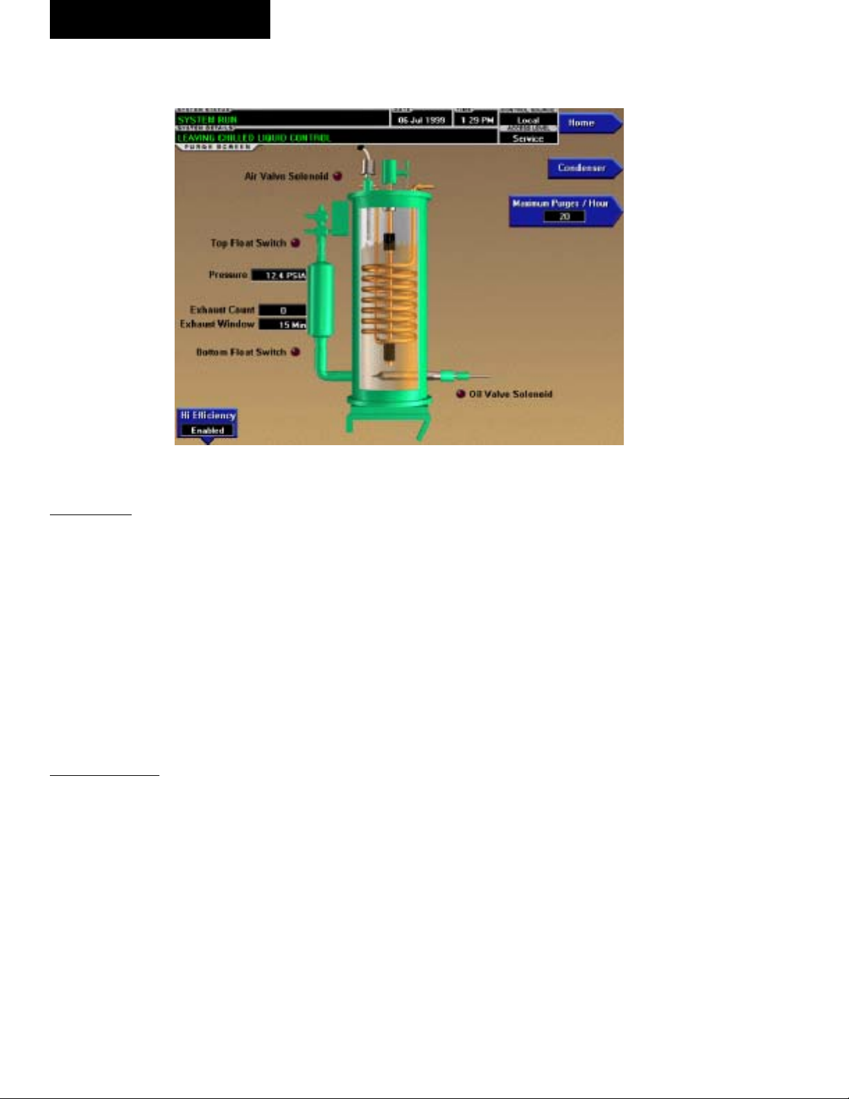
PURGE SCREEN
FIG. 8
OVERVIEW
This screen displays a cutaway view of the Purge Tank.
LED’s depict the state of the Float switches, Oil Valve
solenoid and Air Valve solenoid and the purge exhaust
count is displayed. All setpoints relating to the purge
sys tem are maintained on this screen. The Purge tank
oil level, based on the position of the ß oat switches,
is de pict ed through animation. When both the Float
Switch es are closed, the oil level is shown at its lowest
(empty) level. When both Float switches are open, the
level is shown at its highest (full) level. Levels be tween
these ex tremes are shown at midpoint.
DISPLAY ONLY
Air Valve Solenoid (LED)
Illuminated when the Air Valve Solenoid is energized
(open), venting non-condensibles from the Purge tank.
Oth er wise, extinguished. For High EfÞ ciency (pump
assisted) purge systems, the valve is en er gized at >90.0
PSIA and de-energizes when the pressure decreases to
<80.0 PSIA. For non-assisted purge systems, the valve
is energized at >34.7 PSIA and de-energized when the
pressure decreases to <29.7 PSIA.
00351VIP
Ex tin guished when it is open, indicating the level is at
max i mum (full).
Bottom Float Switch (LED)
Illuminated when the Bottom Float Switch is closed, in di cat ing the Purge Tank oil level is at minimum (emp ty).
Extinguished when it is open, indicating the oil level is
above minimum.
Oil Valve Solenoid (LED)
Illuminated when the Oil Valve Solenoid is energized,
Þ lling the Purge Tank with oil. Extinguished when it is
de-energized, draining the oil from the Purge tank.
Pressure
Displays the pressure in the Purge Tank.
Exhaust Count
Displays the number of purge exhausts that have oc curred within the last 0 to 60 minutes, as displayed in
the Exhaust Window. After a 60 minute bypass at chill er
start, purge exhausts are counted until the Excess Purge
threshold is reached or the chiller shuts down, where up on the count is frozen. The count will be reset when
the chiller starts.
Top Float Switch (LED)
Illuminated when the Top Float Switch is closed,
in di cat ing the Purge Tank oil level is less than full.
24
Exhaust Window
Displayed as 0 to 60 minutes. After a 60 minute bypass
at chiller start, the Exhaust Window increments from 0
YORK INTERNATIONAL
Page 25

FORM 160.55-O1 (604)
to 60. During this period, purge exhausts are counted
and the Exhaust Count displayed is that which has oc curred in the last number of minutes displayed in the
Exhaust Window. After the Exhaust Window reaches
60, the purge exhausts that occurred in the oldest minute are discarded from the Exhaust Count and exhausts
from the most recent minute are shifted in, providing a
roll ing count of purge exhausts that occurred in the last
60 minutes. It remains at 60 until the chiller is restarted,
whereupon it is reset to 0.
Bypass Time Left
Replaces “Exhaust Window” label during the Þ rst 60
minutes of chiller run. Counts down the 60 minute purge
count bypass.
PROGRAMMABLE
High Effi ciency Purge System (Enabled/Disabled)
Access Level Required: SERVICE
Selects the appropriate control and purge exhaust
thresh olds for the installed purge system. High EfÞ -
ciency (pump assisted) purge systems exhaust at >90.0
PSIA. Non pump-assisted purge systems exhaust at
>34.7 PSIA.
Maximum Purges/Hour
Access Level Required: OP ER A TOR/SERVICE
Allows the user to deÞ ne the number of purge air ex-
hausts permitted before an Excess Purge Warning is displayed. With OPERATOR access lev el, the value can be
pro grammed over a range of 10 to 30 Purges/Hour. Service Technicians, in SERVICE ac cess level can pro gram
this setpoint over a greater range. Service Tech ni cians
refer to YORK Service Manual 160.55-M1.
NAVIGATION
Home
Access Level Required: VIEW
Causes an instant return to the Home Screen.
Condenser
Access Level Required: VIEW
Causes an instant return to the Condenser Screen.
2
YORK INTERNATIONAL
25
Page 26
OptiView Control Center
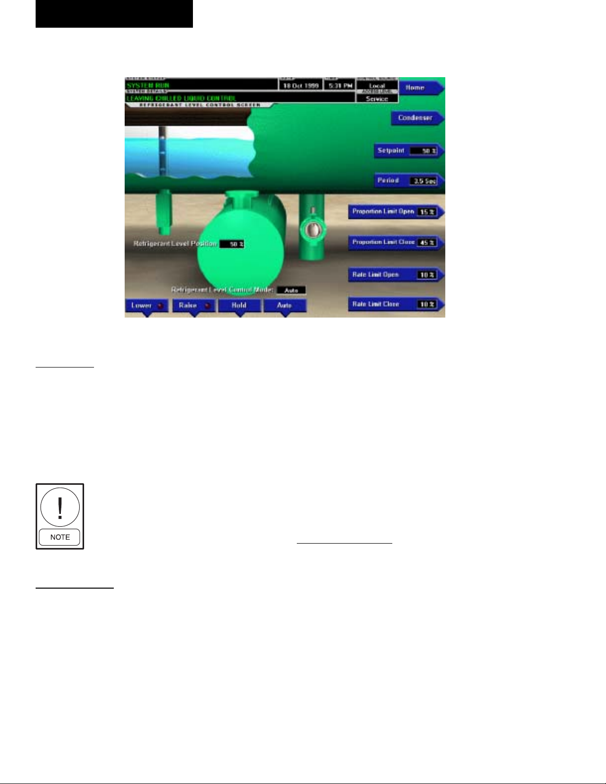
REFRIGERANT LEVEL CONTROL SCREEN
FORM 160.55-O1 (604)
FIG. 9
OVERVIEW
This screen displays a cutaway view of the chiller con dens er, along with the liquid refrigerant level sensor and
the ß ow control valve. All setpoints relating to the liq uid
level control are maintained on this screen. Through
animation, the variable oriÞ ce position is dis played. In
addition, the refrigerant ß ow control valve (variable
or i Þ ce) can be man u al ly op er at ed.
Requires a login ac cess level of
SERVICE. Service Tech ni cians re fer
to YORK Service Manual 160.55-M1
for operation in struc tions and ex pla na tion of all pro gram ma ble setpoints
and dis played values.
DISPLAY ONLY
Refrigerant Level Position
Displays the present position of the liquid level. The
re frig er ant level is animated in the cutaway view of the
condenser. When the actual level is 0% to 15%, the level
is shown about 50% full. When the actual level is 16%
to 31%, the level is shown about 60% full. When the
actual lev el is 32% to 47%, the level is shown about 70%
full. When the actual level is 48% to 63%, the level is
shown about 80% full. When the actual level is 64% to
79%, the level is shown as about 90% full. Ac tu al levels
above 79%, shown as 100% full.
00303VIP
Refrigerant Level Control Mode
Indicates whether the liquid level control is under man u al or automatic control.
Raise (LED)
Is ON when the digital output controlling the Level
Raise contact is on.
Lower (LED)
Is ON when the digital output controlling the Level
Low er contact is on.
PROGRAMMABLE
[Refrigerant Level] Setpoint
Service Technicians refer to YORK Service Manual
160.55-M1.
[Refrigerant Level Control] Period
Service Technicians refer to YORK Service Manual
160.55-M1.
[Refrigerant Level Control] Proportional
Limit Open
Service Technicians refer to YORK Service Manual
160.55-M1.
26
YORK INTERNATIONAL
Page 27

FORM 160.55-O1 (604)
[Refrigerant Level Control] Proportional
Limit Close
Service Technicians refer to YORK Service Manual
160.55-M1.
[Refrigerant Level Control] Rate Limit Open
Service Technicians refer to YORK Service Manual
160.55-M1.
[Refrigerant Level Control] Rate Limit Close
Service Technicians refer to YORK Service Manual
160.55-M1.
[Refrigerant Level Control] Raise (Man u al)
This key puts the level control into manual mode and
sends a RAISE command to the variable oriÞ ce.
[Refrigerant Level Control] Lower (Manual)
This key puts the level control into manual mode and
sends a LOWER command to the variable oriÞ ce.
[Refrigerant Level Control] Hold (Manual)
This key puts the level control into manual mode and
sends a HOLD command to the variable oriÞ ce.
[Refrigerant Level Control] Auto
Returns the Level Control to automatic mode.
NAVIGATION
Home
Ac cess Level Re quired: VIEW
Causes an instant return to the Home Screen.
Condenser
Ac cess Level Re quired: VIEW
Return to the Condenser Screen.
2
YORK INTERNATIONAL
27
Page 28
OptiView Control Center
FORM 160.55-O1 (604)
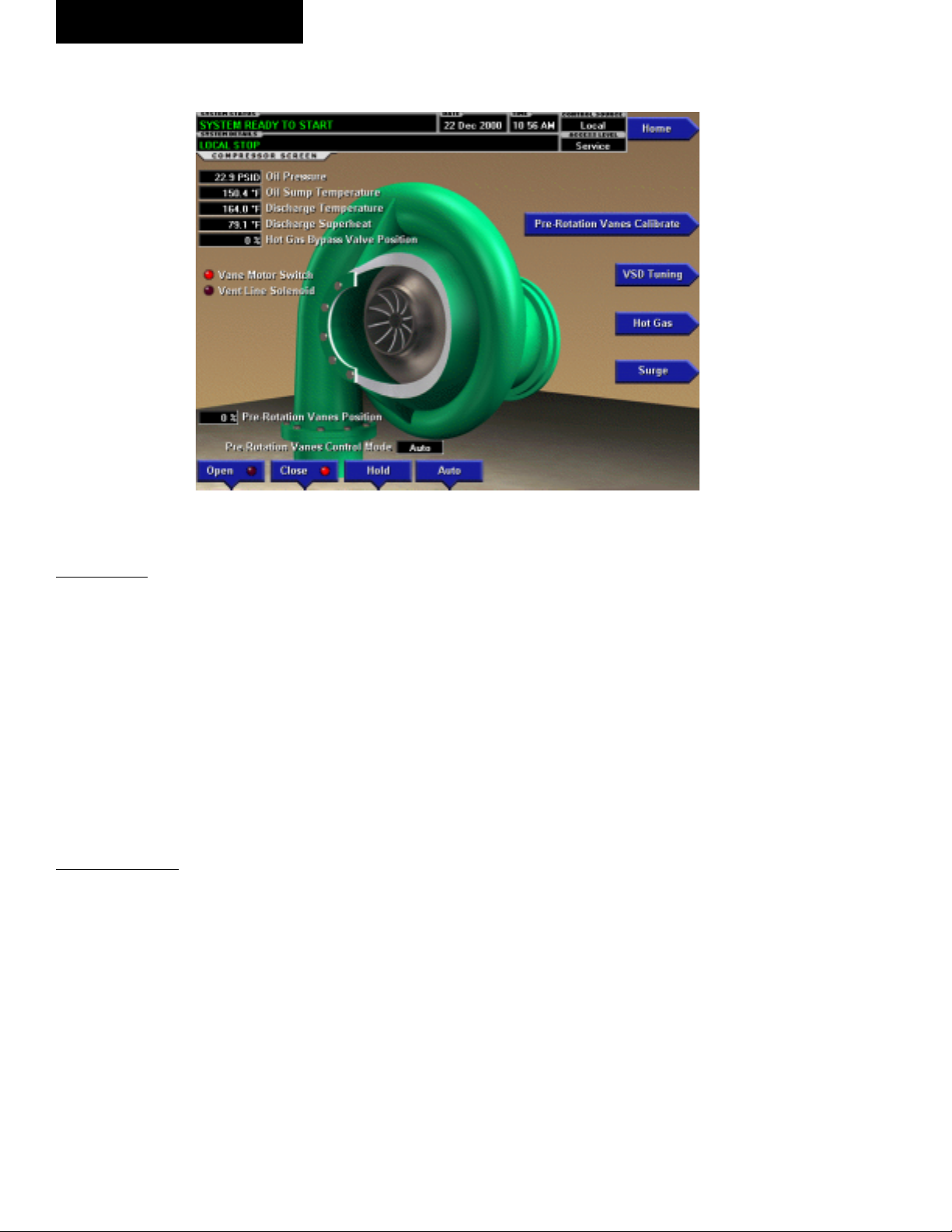
COMPRESSOR SCREEN
FIG. 10
OVERVIEW
This screen displays a cutaway view of the chiller com pres sor, revealing the impeller and shows all con di tions
as so ci at ed with the compressor. In addition, with the
proper Access Level, the pre-rotation vanes may be
manually controlled. Animation of the com pres sor
im pel ler indicates whether the chiller is pres ent ly in a
RUN condition. This screen also serves as a gateway
to subscreens for cal i brat ing the pre-rotation vanes, cal i brat ing the proximity probe, conÞ guring the Hot Gas
By pass or providing advanced control of the com pres sor
motor Variable Speed Drive.
DISPLAY ONLY
Oil Pressure
Displays the pressure differential between the high side
oil pressure transducer (compressor bearing input) and
the low side oil pressure transducer (oil sump). If ei ther
of the trans duc ers used to calculate this dif fer en tial is
out of range, the display Þ eld will show XX.X.
Oil Sump Temperature
Displays the temperature of the oil in the sump
Discharge Temperature
Displays the temperature of the refrigerant in its gas eous
state at discharge of the compressor as it travels to the
condenser.
00483VIP
Superheat Temperature
Displays the discharge superheat temperature, cal cu lat ed as (Discharge temperature – Condenser Sat u rat ed
temperature).
Vane Motor Switch (LED)
Illuminates when the vanes are completely closed.
Vent Line Solenoid (LED)
Illuminates when the solenoid is energized.
Pre-Rotation Vanes Control Mode
Access Level Re quired: SER VICE
Indicates whether the vanes are under manual or au to mat ic control.
[Pre-Rotation Vanes] Open (LED)
Access Level Required: SERVICE
Indicates whether the vanes are in the process of open ing.
[Pre-Rotation Vanes] Close (LED)
Access Level Re quired: SER VICE
Indicates whether the vanes are in the process of clos ing.
Pre-Rotation Vanes Position
(Variable Speed Drive only)
Access Level Required: SERVICE
This value displays the present position of the pre-ro ta tion vanes as a percentage between 0 and 100%.
28
YORK INTERNATIONAL
Page 29

Full Load Amps
Access Level Re quired: SER VICE
Displays the motor current as a percentage of the Full
Load Amps (FLA) value.
Phase A, B, C Current (Solid State Starter only)
Access Level Required: SERVICE
Displays the 3-phase motor current values being read
from the Solid State Starter.
PROGRAMMABLE
[Pre-Rotation Vanes] Open (Manual)
Access Level Required: SERVICE
This key puts the vane control into manual mode and
sends an OPEN command to the vanes.
[Pre-Rotation Vanes] Close (Manual)
Access Level Required: SERVICE
This key puts the vane control into manual mode and
sends a CLOSE command to the vanes.
[Pre-Rotation Vanes] Hold (Manual)
Access Level Re quired: SER VICE
This key puts the vane control into manual mode and
sends a HOLD command to the vanes.
[Pre-Rotation Vanes] Auto
Access Level Required: SERVICE
This key returns the vane control to automatic mode.
FORM 160.55-O1 (604)
Pre-Rotation Vane Calibration
Access Level Re quired: SER VICE
Only available if the chiller is stopped and the system
uses a Variable Speed Drive or Hot Gas Bypass con trol. Moves to the subscreen allowing calibration of the
Pre-rotation vanes. Service Technicians refer to YORK
Service Manual 160.55-M1.
VSD TUNING (Variable Speed Drive only)
Access Level Required: SERVICE
Moves to the subscreen allowing advanced tuning of
the Variable Speed Drive. Service Technicians refer to
YORK Service Manual 160.55-M1.
Hot Gas
Access Level Required: SERVICE
Moves to the subscreen that allows programming of the
Hot Gas Bypass control setpoints and manual con trol
of the Hot Gas Bypass valve. Only displayed if Hot gas
Bypass feature has been enabled on the OP ER A TIONS
Screen. Service technicians refer to YORK Service
Manual 160.55-M1.
Surge
(Flash memory Card version C.MLM.02.02.xxx and
lat er)
Access Level Required: VIEW
Moves to the sub-screen that allows viewing and
pro gram ming of the Surge Protection feature. Service
Tech ni cians refer to Service Manual 160.55-M1.
2
NAVIGATION
Home
Access Level Required: VIEW
Causes an instant return to the Home Screen.
YORK INTERNATIONAL
29
Page 30
OptiView Control Center
OptiView Control Center
FORM 160.55-O1 (604)
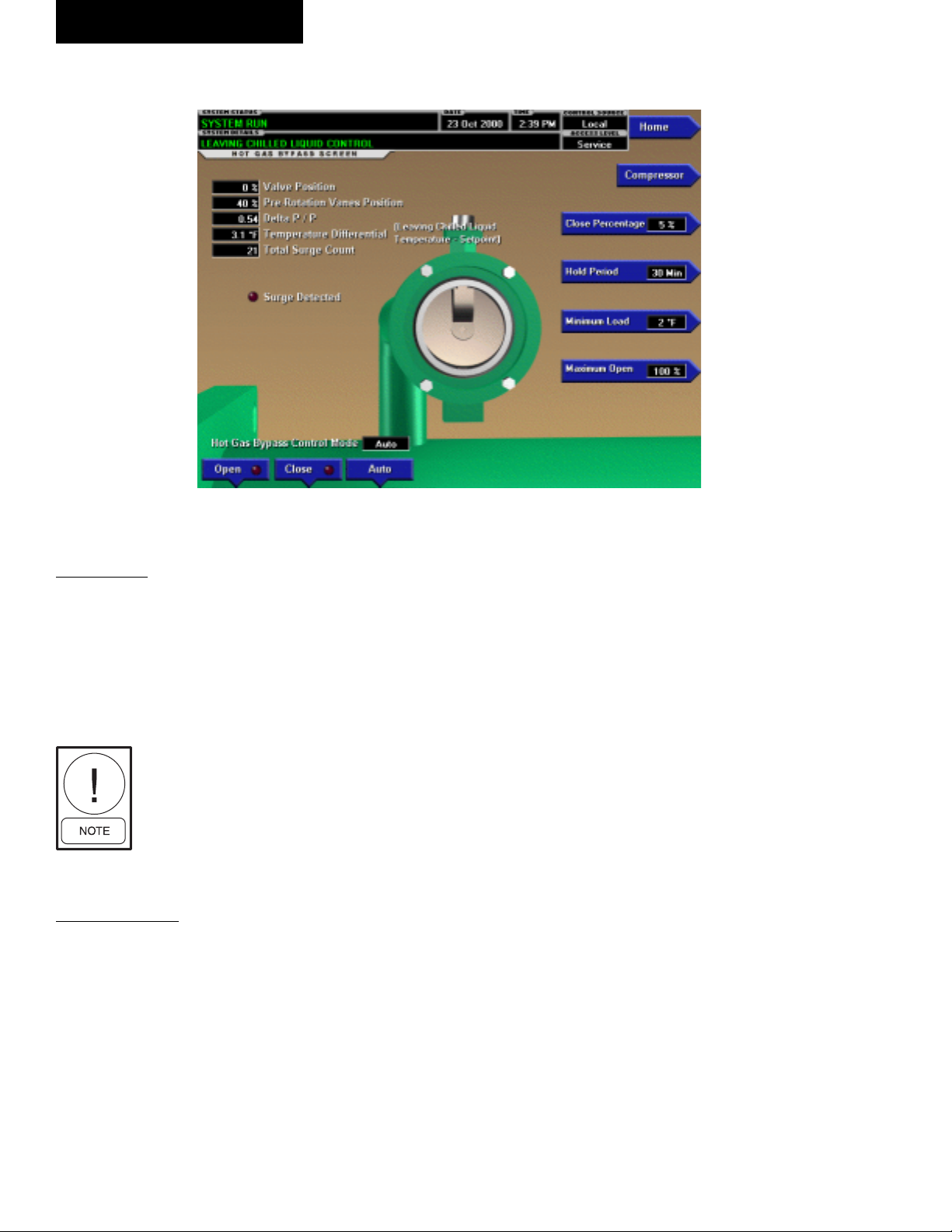
HOT GAS BYPASS SCREEN
FIG. 11
OVERVIEW
This screen displays a cutaway view of the Hot Gas By pass
Valve. All setpoints relating to Hot Gas Bypass con trol are
maintained on this screen. Also, related Hot Gas Bypass
control parameters are displayed for ref er ence. Through
animation, the relative valve position is dis played. In addition, the valve can be manually op er at ed.
Requires access level of SERVICE.
Ser vice Tech ni cians refer to YORK
Service Man u al 160.55-M1 for op er a tion in struc tions and explanation
of all pro gram ma ble setpoints and
dis played val ues.
DISPLAY ONLY
Valve Position
Displays the position of the Hot Gas valve over the
range of 0% (closed) to 100% (fully open). The valve
position is animated. When the actual position is 0% to
19%, the valve is shown fully closed. When actual position is 20% to 39% the valve is shown 25% open. When
ac tu al po si tion is 40% to 59%, the valve is shown 50%
open. When actual position is 60% to 79%, the valve is
shown as 75% open. Positions greater than 79% shown
as full open.
00476VIP
Pre-rotation Vanes Position
Displays the position of the Pre-Rotation Vanes over the
range of 0% (closed) to 100% (fully open). Dis played
at XXX until calibration procedure is per formed by
service technician.
Delta P/P
A parameter that represents system differential or
“Head”. It is calculated as [(condenser pressure – evap o ra tor pressure) / evaporator pressure].
Temperature Differential
The difference between the Leaving Chilled Liquid Tem per a ture and the Leaving Chilled Liquid Tem per a ture
Setpoint. It is cal cu lat ed by sub tract ing the Leav ing
Chilled Liq uid tem per a ture from the Leav ing Chilled
Liquid Tem per a ture Setpoint.
Total Surge Count
This is the total number of surge events that have been
detected over the lifetime of the chiller. These are the
surge events detected by the Surge Protection feature.
The surge events detected by the compressor Variable
Speed Drive Adaptive Capacity Control Board are not
included in this total.
Surge Detected (LED)
Illuminated for 5 seconds each time a surge is detected
by the Surge Protection feature. It does not illuminate
30
YORK INTERNATIONAL
Page 31

FORM 160.55-O1 (604)
in response to surge events detected by the compressor Variable Speed Drive Adaptive Capacity Control
Board.
Hot Gas Bypass Control Mode
Indicates whether the Hot Gas Bypass is under au to mat ic,
manual or override control. “Override” is dis played during Minimum Load over ride conditions or when the
Compressor Motor Variable Speed (if equipped) Drive
is run ning at less than maximum speed.
PROGRAMMABLE
Close Percentage
Service technicians refer to YORK Service Manual
160.55-M1.
Hold Period
Service technicians refer to YORK Service Manual
160.55-M1.
Surge Sensitivity
(Flash Memory Card version C.MLM.02.01.xxx and
earlier. On SURGE PRO TEC TION Screen in later
Flash Memory Card ver sions)
Service technicians refer to YORK Service Manual
160.55-M1.
Maximum Open
(Flash Memory Card version C.MLM.02.02.xxx
and later)
Service Technicians refer to YORK Ser vice Man u al
160.55-M1.
[Hot Gas Bypass Control] Open (Manual)
This key puts the Hot Gas Bypass Control in manual
mode and increases the valve position by 5%.
[Hot Gas Bypass Control] Close (Manual)
This key puts the Hot Gas Bypass Control in manual
mode and decreases the valve position by 5%.
[Hot Gas Bypass Control] Auto
Returns the Hot Gas Bypass Control to automatic
mode.
NAVIGATION
Home
Access Level Required: VIEW
Causes an instant return to the Home Screen.
Compressor
Access Level Required: VIEW
Causes an instant return to the Compressor Screen.
2
Minimum Load
Service technicians refer to YORK Service Manual
160.55-M1.
YORK INTERNATIONAL
31
Page 32

OptiView Control Center
FORM 160.55-O1 (604)
SURGE PROTECTION SCREEN
FIG. 12
OVERVIEW
(This feature applies to Flash Memory Card ver sion
C.MLM.02.02.xxx and later)
This screen displays a cutaway view of the chiller
com pres sor and all parameters relating to the Surge
Pro tec tion feature. All setpoints relating to this fea ture
are maintained on this screen.
DISPLAY ONLY
Delta P/P
A parameter that represents the system differential or
“Head pressure”. It is calculated as (condenser pres sure
– evaporator pressure) / evaporator pres sure.
Surge Window Time
When the chiller enters run mode, this value counts
up to the time pro grammed as the COUNT WIN DOW
setpoint. When it reach es the COUNT WIN DOW min utes, the num ber of surge events in the oldest minute is
dis card ed and the number of surge events in the most
recent minute is added, thus pro vid ing a rolling count
of the total surge events that have occurred in the last
COUNT WINDOW min utes. This val ue is reset when
the chiller shuts down.
Surge Window Count
Displays the number of surge events that have oc-
00482VIP
curred in the last 1 to 5 minutes as programmed with
the COUNT WINDOW setpoint. If the chiller has been
running for less than the COUNT WINDOW minutes, it
is the number of surge events that have occurred with in
the last number of minutes dis played as the SURGE
WINDOW TIME. The count is cleared when the chiller
shuts down.
Surge Detected (LED)
Illuminates for 5 seconds each time a surge is de tect ed
by the Surge Protection feature. It does not illuminate
in response to surge events detected by the compressor Variable Speed Drive Adaptive Capacity Control
Board.
Total Surge Count
Displays the total number of surge events detected over
the lifetime of the unit (up to a maximum of 65535).
These are the surge events detected by the Surge Protection feature. The surge events detected by the compressor
Variable Speed Drive Adaptive Capacity Control Board
are not included in this total.
Extended Run Time Remaining
Displays the time remaining in the 10-minute “EX TEND ED RUN” period. During this period, the Prerotation vanes are driven closed and “Warning – Surge
Protection – Excess Surge Limit” is dis played. Refer to
operation under “Count Limit” below.
32
YORK INTERNATIONAL
Page 33

FORM 160.55-O1 (604)
PROGRAMMABLE
Shutdown (Enabled/Disabled)
Access Level Required: OPERATOR
Allows the user to select whether the chiller will shut down or continue to run when an Excess Surge sit u a tion
has been detected.
If this setpoint is Enabled and the EXTENDED RUN
setpoint is Disabled, a safety shutdown is per formed
when the SURGE WINDOW COUNT exceeds the
COUNT LIMIT setpoint.
If this setpoint is Enabled and the EXTENDED RUN
setpoint is Enabled, a safety shutdown is per formed if
the SURGE WINDOW COUNT exceeds the COUNT
LIMIT setpoint at the completion of the 10 minute Ex tend ed Run period.
“Surge Protection – Excess Surge” is displayed with
either shutdown.
If this setpoint is Disabled, refer to operation under
“Count Limit” below.
setpoint is Enabled, and the SURGE WIN DOW COUNT
exceeds the COUNT LIMIT at the com ple tion of this
period, a safety shutdown is performed and “Surge
Pro tec tion – Excess Surge” is displayed.
If the Hot Gas Bypassed control is Enabled, the Hot Gas
By pass Valve position must be 100% before the Ex tend ed
Run mode is implemented. If the chill er is equipped with a
compressor motor Variable Speed Drive, output fre quen cy
must be at full speed (50 Hz/60 Hz) before the Ex tend ed
Run mode is implemented. If the chiller is equipped with
both Hot Gas Bypass and com pres sor motor Variable Speed
Drive, both of the con di tions must be met before Extended
Run is im ple ment ed.
Count Window
Access Level Required: OPERATOR
Allows the user to deÞ ne the period of time (1 to 5
minutes; default 5 ; default 3 with Software version
C.MLM.02.05.xxx {and later} or C.OPT.02.05.xxx {and
later}) in which the number of surge events (SURGE
WIN DOW COUNT) are compared to the max i mum al lowed (COUNT LIMIT), for the purpose of de tect ing
an excess surge situation.
2
With Software version C.MLM.02.05.xxx (and later) or
C.OPT.02.05.xxx (and later):
• If equipped with a compressor Variable Speed
Drive (VSD), the VSD output frequency must
be at maximum before the SHUTDOWN feature
is implemented or surge warning messages are
displayed.
• If equipped with a VSD and Hot Gas Bypass
(Enabled), the VSD output frequency must be
at maximum AND the Hot Gas Valve must be
at 100% before the SHUTDOWN feature is
implemented or surge warning messages are
displayed.
Extended Run (Enabled/Disabled)
Access Level Required: OPERATOR
Allows the user to select the surge correction/avoid ance
EXTENDED RUN mode. This will be im ple ment ed
when an Excess surge situation is detected as follows:
Anytime the SURGE WINDOW COUNT exceeds the
COUNT LIMIT, the Pre-rotation vanes are driven closed
for the next 10 minutes. While this load inhibit is in effect, “Warn ing – Surge Protection – Excess Surge Limit”
is dis played. When 10 minutes have elapsed, the warn ing message and load inhibit are automatically cleared,
provided the SURGE WINDOW COUNT is less than
or equal to the COUNT LIM IT. If the SHUT DOWN
Count Limit
Access Level Required: OPERATOR
Allows the user to deÞ ne the maximum number of surge
events (4 to 20; default 4; default 15 with Software version C.MLM.02.05.xxx {and later} or C.OPT.02.05.xxx
later}) that can occur within a de Þ ned period of time
{and
before an Excess Surge situation is de tect ed. If the SURGE
WINDOW COUNT exceeds the COUNT LIM IT, an Excess Surge situation has oc curred.
When an Excess Surge situation is detected, the action
de pends upon the following:
• If both the SHUTDOWN and EXTENDED RUN
setpoints are Disabled, the chiller will continue to
run, dis play ing the message “Warning – Excess
Surge detected”. See Hot Gas Bypass and Variable
Speed Drive exceptions above.
• If the SHUTDOWN setpoint is Enabled and the
EX TEND ED RUN setpoint is Disabled, the chiller
will per form a safety shutdown and display “Surge
Protection – Excess Surge”. See Hot Gas Bypass
and Variable Speed Drive exceptions above.
• If the SHUTDOWN setpoint is Disabled and the
EX TEND ED RUN setpoint is Enabled, the Pre-rotation Vanes are driven closed for 10 minutes and
“Warning – Surge Pro tec tion – Excess Surge Lim it”
is displayed. When the 10 minutes have elapsed,
YORK INTERNATIONAL
33
Page 34

OptiView Control Center
FORM 160.55-O1 (604)
if the SURGE WINDOW COUNT is less than or
equal to the COUNT LIMIT, this message and load
inhibit are au to mat i cal ly cleared. Al ter nat ing with
this message is “Warning – Excess Surge De tect ed”
that continues after the 10 minute pe ri od has elapsed
until man u al ly cleared with the Warning Reset key.
See Hot Gas By pass and Variable Speed Drive exception above.
• If both the SHUTDOWN and EXTENDED RUN
setpoint are Enabled, the 10 minute Extended RUN
mode is in voked as described above. However, if the
SURGE WIN DOW COUNT exceeds the COUNT
LIMIT at the completon of the 10 minute extended
run period, a safety shutdown is per formed and
“Surge Protection – Excess Surge” is dis played. See
Hot Gas By pass and Variable Speed Drive exception
above.
Surge Sensitivity
Access Level Required: SERVICE
Allows the user to deÞ ne the surge detection sen si tiv i ty.
Se lect able over the range of 0.3 to 1.3; default 0.3. The
smaller the number, the greater the sensitivity.
Clear Surge Count
Access Level Required: ADMIN
Allows user to set the Total Surge Count to zero.
NAVIGATION
Home
Access Level Required: VIEW
Causes an instant return to the Home Screen
Compressor
Access Level Required: VIEW
Causes an instant return to the Compressor Screen.
34
YORK INTERNATIONAL
Page 35

FORM 160.55-O1 (604)
2
THIS PAGE INTENTIONALLY LEFT BLANK
TO MAINTAIN FORMAT
YORK INTERNATIONAL
35
Page 36

OptiView Control Center
PRE-ROTATION VANES CALIBRATION SCREEN
FORM 160.55-O1 (604)
FIG. 13
OVERVIEW
This screen displays a cutaway view of the chiller com pres sor, revealing the pre-rotation vanes and pro vides
the capability of calibrating the pre-rotation vanes for
either Variable Speed Drive or Hot Gas By pass ap pli ca tions.
Requires a login ac cess level of SER VICE. Service Technicians refer to
YORK Service Manual 160.55-M1
for operation instructions and ex pla na tion of all programmable setpoints
and displayed values.
DISPLAY ONLY
Pre-Rotation Vanes Opening (LED)
Indicates the vanes are opening.
Pre-Rotation Vanes Closing (LED)
Indicates the vanes are closing.
00354VIP
Hot Gas PRV Voltage
Displays the Pre-rotation Vanes position potentiometer feed back voltage when the Hot Gas Feature is
En abled.
PROGRAMMABLE
Start Calibration
This option is hidden after cal i bra tion has start ed.
Ser vice Technicians refer to YORK Ser vice Manual
160.55-M1 for an ex pla na tion of this setpoint.
Cancel Calibration
This option only becomes available after calibration
has started. Service Technicians refer to YORK Service
Man u al 160.55-M1 for an explanation of this setpoint.
NAVIGATION
Home
Access Level Required: VIEW
Causes an instant return to the Home Screen.
Calibration in Progress (LED)
Indicates the calibration sequence is in progress.
Calibration Messages
These are text messages which step the user through the
calibration process and indicate its success or fail ure.
36
Compressor
Access Level Required: VIEW
Return to the Compressor Screen.
YORK INTERNATIONAL
Page 37

THIS PAGE INTENTIONALLY LEFT BLANK
TO MAINTAIN FORMAT
FORM 160.55-O1 (604)
2
YORK INTERNATIONAL
37
Page 38

OptiView Control Center
FORM 160.55-O1 (604)
VSD TUNING SCREEN
FIG. 14
OVERVIEW
This screen displays a cutaway view of the chiller com pres sor, revealing the pre-rotation vanes and pro vides
the capability of manually controlling the pre-rotation
vanes. Animation of the pre-rotation vanes indicates
the pre-rotation vane position. In addition, this screen
al lows manual control of the fre quen cy com mand be ing
sent to the Variable Speed Drive.
Re quires a login access level of
SERVICE. Service Technicians re fer
to YORK Service Manual 160.55-M1
for operation instructions and ex pla na tion of all programmable setpoints
and displayed values.
DISPLAY ONLY
Output Frequency
Displays the Output Frequency reported by the Vari able
Speed Drive.
Temperature Differential
Displays the differential between the Leaving Chilled
Liquid Temperature and Setpoint.
00477VIP
Delta P/P
Displays a value based on the pressure differential
be tween the Evaporator and Condenser pressures.
[(Condenser – Evaporator) / Evaporator]
Pre-Rotation Vanes Control Mode
Indicates whether the vanes are under manual or au to mat ic control.
[Pre-Rotation Vanes] Open (LED)
Indicates whether the vanes are in the process of
opening.
[Pre-Rotation Vanes] Close (LED)
Indicates whether the vanes are in the process of
closing.
Pre-Rotation Vane Position
This value displays the present position of the pre-ro ta tion vanes as a percentage between 0 and 100%.
[VSD] Command Frequency
Displays the frequency value being sent to the Adap tive
Capacity Control.
[VSD] Frequency Control Mode (Manual / Auto)
Displays the present state of the command frequency
control.
38
YORK INTERNATIONAL
Page 39

FORM 160.55-O1 (604)
Output Current – Phase A, B, C
(Flash Memory Card version C.MLM.02.02.xxx
and later)
Displays the phase current measured to the motor.
PROGRAMMABLE
Set
Allows manual programming of the command fre quen cy
value. Manually programming this value will put the
VSD frequency control into manual mode.
Auto
Following manual programming of the command fre quen cy, this returns the system to automatic control.
Fixed
This key puts the VSD frequency control into Þ xed speed
mode and constantly sends the maximum fre quen cy to
the Variable Speed Drive control.
Incr Amount
DeÞ nes the amount by which the Increase and De crease
commands will modify the present VSD command fre quen cy.
Increase
This key puts the VSD frequency control into manual
mode and increases the present command fre quen cy by
the deÞ ned frequency increment. It will not raise the
value above the maximum allowed frequency.
Decrease
This key puts the VSD frequency control into manual
mode and decreases the present command frequency by
the deÞ ned frequency increment. It will not lower the
value below one (1) Hz.
[Pre-Rotation Vanes] Open (Manual)
This key puts the vane control into manual mode and
sends an OPEN command to the contacts.
[Pre-Rotation Vanes] Close (Manual)
This key puts the vane control into manual mode and
sends a CLOSE command to the contacts.
[Pre-Rotation Vanes] Hold (Manual)
This key puts the vane control into manual mode and
sends a HOLD command to the contacts.
[Pre-Rotation Vanes] Auto
Returns Vane Control to automatic mode.
NAVIGATION
Home
Access Level Required: VIEW
Causes an instant return to the Home Screen.
Compressor
Access Level Required: VIEW
Return to the Compressor Screen.
2
YORK INTERNATIONAL
39
Page 40

OptiView Control Center
FORM 160.55-O1 (604)
OIL SUMP SCREEN
FIG. 15
OVERVIEW
This screen displays a close-up of the chiller oil
sump.
DISPLAY ONLY
Oil Sump Temperature
Displays the temperature of the oil in the sump.
Oil Pressure
Displays the pressure differential between the high side
oil pressure transducer (output of oil Þ lter) and the low
side oil pressure transducer (compressor housing). If
either of the transducers used to calculate this dif fer en tial is out of range, the display Þ eld will show XX.X.
Oil Pump Run Output (LED)
Indicates whether the Oil Pump is being commanded
to operate.
00356VIP
Manual Oil Pump Operation Time Left
Displays the time remaining in the 10-minute manual
oil pump operation described below.
PROGRAMMABLE
Manual Pump
Access Level Required: OPERATOR
This key puts the Oil Pump control in Manual Mode and
forces it to RUN. The Oil Pump is limited to run ning for
a maximum of ten (10) minutes. If a longer running time
is desired, this key must be pressed again. Manual Oil
Pump control is disabled (and the button hidden) during
system prelube, system run and system coastdown.
NAVIGATION
Home
Access Level Required: VIEW
Causes an instant return to the Home Screen.
40
YORK INTERNATIONAL
Page 41

ELECTRO-MECHANICAL STARTER SCREEN
FORM 160.55-O1 (604)
2
FIG. 16
OVERVIEW
This screen displays all information pertaining to an
Electro-Mechanical Starter.
DISPLAY ONLY
Motor Run (LED)
Indicates whether the digital output from the controls
is commanding the motor to RUN.
Motor Current % Full Load Amps
Displays the motor current as a percentage of the Full
Load Amps (FLA) value. For the Electro-Mechanical
Starter this is the data returned by the CM-2 board.
Current Limit Setpoint
Displays the current limit value in use. This value could
come from a 0-20mA, 4-20mA, 0-10VDC or 2-10VDC
input in An a log Re mote mode, PWM signal in Digital
Re mote mode, MicroGateway in ter face in ISN mode
or a lo cal ly pro grammed value.
Pulldown Demand Time Left
Displays the time remaining in the programmed pulldown period if the value is non-zero.
00357VIP
PROGRAMMABLE
Local Motor Current Limit
Access Level Required: OPERATOR
Allows the user to specify the maximum allowed mo tor current (as a percentage of FLA). When the motor
cur rent reaches this value, the pre-rotation vanes will
not be permitted to open further. If the motor current
rises above this value, the pre-rotation vanes will close
to reduce the current to this value.
Pulldown Demand Limit
Access Level Required: OPERATOR
Allows the user to specify the current limit value (as a
percentage of FLA) to which the chiller will be limited
during the speciÞ ed pulldown limit time. This value will
override the Motor Current Limit value during this time
period. This function is used to provide energy savings
following chiller start-up.
Pulldown Demand Time
Access Level Required: OPERATOR
Allows the user to set a period of time for which the pulldown demand limit will be in effect after the chiller starts.
NAVIGATION
YORK INTERNATIONAL
Home
Access Level Required: VIEW
Causes an instant return to the Home Screen.
41
Page 42

OptiView Control Center
MOD “A” SOLID STATE STARTER SCREEN
FORM 160.55-O1 (604)
FIG. 17
OVERVIEW
This screen displays all information pertaining to the
Mod “A” Solid State Starter.
DISPLAY ONLY
Motor Run (LED)
Indicates whether the digital output from the controls is
commanding the motor to RUN.
Motor Current % Full Load Amps
Displays the motor current as a percentage of the Full
Load Amps (FLA) value. For the Solid State Starter this
is the data returned by the Starter Logic board.
Current Limit Setpoint
Displays the current limit value in use. This value could
come from a 0-20mA, 4-20mA, 0-10VDC or 2-10VDC
input in An a log Remote mode, PWM signal in Digital
Remote mode, MicroGateway interface in ISN mode or
a lo cal ly pro grammed value in local mode.
Pulldown Demand Time Left
Displays the time remaining in the pro grammed pulldown period.
Scale/Model
Display information about the Liquid Cooled-Solid
State Starter Rating and the maximum allowed Full
Load Amps.
0058VIP
Voltage - Phase A, B, C
Display the 3-phase input line voltage values being read
from the Solid State Starter.
Current - Phase A, B, C
Display the 3-phase motor current values being read
from the Solid State Starter.
PROGRAMMABLE
Local Motor Current Limit
Access Level Required: OP ER A TOR
Allows the user to specify the maximum al lowed mo tor current (as a percentage of FLA). When the motor
cur rent reaches this value, the pre-rotation vanes will
not be permitted to open further. If the motor current
rises above this value, the pre-rotation vanes will close
to reduce the current to this value.
Pulldown Demand Limit
Access Level Required: OP ER A TOR
Allows the user to specify the current limit val ue (as a
percentage of FLA) to which the chiller will be limited
during the speciÞ ed pulldown limit time. This value will
override the Motor Current Limit value during this time
period. This function is used to provide energy sav ings
following chiller start-up.
Pulldown Demand Time
Access Level Required: OP ER A TOR
42
YORK INTERNATIONAL
Page 43

FORM 160.55-O1 (604)
Allows the user to set a period of time for which the
pulldown demand limit will be in effect after the chiller
starts.
Full Load Amps
Access Level Required: SER VICE
DeÞ ne the maximum amps at which the motor can op-
er ate. This value is viewable when logged in under the
Operator or View access level. Service Technicians re fer
to YORK Service Manual 160.55-M1.
Supply Voltage Range
Access Level Required: SERVICE
Allows the user to select a speciÞ c voltage range for volt-
age checking. When not disabled, this line voltage range
is used to determine a low line and high line volt age
threshold for initiating a shutdown. Service Tech ni cians
refer to YORK Service Manual 160.55-M1.
Current Unbalance Check (Enabled / Dis abled)
Access Level Re quired: SER VICE
Allows the user to control whether the logic checks for
current unbalance and initiates a shutdown as a result.
Service Technicians refer to YORK Service Manual
160.55-M1.
2
NAVIGATION
Home
Access Level Re quired: VIEW
Causes an instant return to the Home Screen.
YORK INTERNATIONAL
43
Page 44

OptiView Control Center
MOD “B” SOLID STATE STARTER SCREEN
FORM 160.55-O1 (604)
FIG. 18
OVERVIEW
This screen displays all information pertaining to the
Mod “B” Solid State Starter.
DISPLAY ONLY
Motor Run (LED)
Indicates whether the digital output from the controls is
commanding the motor to RUN.
Motor Current % Full Load Amps
Displays the motor current as a percentage of the Full
Load Amps (FLA) value.
Current Limit Setpoint
Displays the current limit in use. This value could come
from a 0-20mA, 4-20mA, 0-10VDC or 2-10VDC input
in Analog Remote Mode, PWM signal in Digital Re mote
Mode, MicroGateway interface in ISN remote Mode or
a lo cal ly programmed value in Local Mode.
00359VIP
kW Hours
Displays the cumulative amount of kilowatts used over
time.
Starter Model
Displays the Solid State Starter model that is applied to
the chiller. Starter Models are 7L, 14L, 26L or 33L.
Voltage – Phase A, B, C
Displays the 3-phase input line voltage measured by the
Solid State Starter.
Current – Phase A, B, C
Displays the 3-phase motor current values measured by
the Solid State Starter.
Temperature – Phase A, B, C
Displays the temperatures of the Silicon Controlled
Rec ti Þ er assemblies.
PROGRAMMABLE
Pulldown Demand Time Left
Displays the time remaining in the programmed pulldown period.
Input Power
Displays the Kilowatts measured by the Solid State
Start er.
44
Local Motor Current Limit
Access Level Required: OPERATOR
Allows the user to specify the maximum al lowed mo tor
current (as percentage of FLA). When the mo tor cur rent
reaches this value, the Pre-rotation Vanes will not be
permitted to open fur ther. If the motor rises above this
value, the Pre-ro ta tion Vanes will close to reduce the
current to this value.
YORK INTERNATIONAL
Page 45

FORM 160.55-O1 (604)
Pulldown Demand Limit
Access Level Required: OPERATOR
Allows the user to specify the current limit val ue (as a
per cent age of FLA) to which the chill er will be limited
dur ing the speciÞ ed pulldown time. This value will
over ride the Motor Cur rent Limit value dur ing this time
pe ri od. This function is used to provide energy sav ings
fol low ing chiller start.
Pulldown Demand Time
Access Level Required: OPERATOR
Allows the user to set a period of time for which the
pulldown demand limit will be in effect after the chill er
starts.
Full Load Amps
Access Level Required: SERVICE
DeÞ nes the maximum amps at which the motor can oper-
ate. This value is viewable when logged in at Op er a tor
or View access level. Service technicians refer to YORK
Service Manual 160.55-M1.
Voltage Range
Access Level Required: SERVICE
Allows the user to select speciÞ c line voltage range for
voltage checking. When not disabled, this line voltage
range is used to determine a low line and high line volt age threshold for initiating a shutdown. Service Tech ni cians refer to YORK Service Manual 160.55-M1.
Starting Current
Access Level Required: SERVICE
DeÞ nes the maximum allowed motor starting amps. The
Solid State Starter will limit the motor starting current
to this value. Service technicians refer to YORK Ser vice
manual 160.55-M1.
Open SCR (Enabled/Disabled)
Access Level Required: SERVICE
Allows the user to enable or disable the Solid State
Start er Open SCR safety detection. This must never
be dis abled unless under advisement of the YORK
Fac to ry. Service Technicians refer to YORK Service
Man u al 160.55-M1.
2
Shorted SCR (Enabled/Disabled)
(Flash Memory Card version C.MLM.02.01 or later)
Access Level required: SERVICE
Allows the user to enable or disable the Solid State
Start er Shorted SCR safety detection. This must never
be dis abled unless under advisement of the York Fac to ry. Service Technicians refer to YORK Service Man u al
160.55-M1.
kWH Reset
Access Level Required: SER VICE
Allows the user to reset the cumulative Kilowatt Hours.
Service technicians refer to YORK Service Manual
160.55-M1.
NAVIGATION
HOME
Access Level Required: VIEW
Causes an instant return to the HOME Screen.
YORK INTERNATIONAL
45
Page 46

OptiView Control Center
VARIABLE SPEED DRIVE SCREEN
FORM 160.55-O1 (604)
FIG. 19
OVERVIEW
This screen displays information per tain ing to a Vari able
Speed Drive (VSD).
DISPLAY ONLY
Motor Run (LED)
Indicates whether the digital output from the controls is
commanding the motor to RUN.
Motor Current % Full Load Amps
Displays the motor current as a per cent age of the Full
Load Amps (FLA) value.
Current Limit Setpoint
Displays the current limit value in use. This value could
come from a 0-20mA, 4-20mA, 0-10VDC or 2-10VDC
input in An a log Remote mode, PWM signal in Digital
Remote mode, MicroGateway interface in ISN mode or
a lo cal ly pro grammed value.
Pulldown Demand Time Left
Displays the time remaining in the pro grammed pulldown period if the value is non-zero.
Output Voltage
Displays the output voltage measured to the motor.
46
00360VIP
Output Frequency
Displays the present output frequency to the motor.
Output Current - Phase A, B, C
Displays the phase current measured to the motor.
Input Power
Displays the total Kilowatts measured by the VSD or
Harmonic Filter, if installed.
kW Hours
Displays the cumulative amount of kilowatts used over
time as the VSD motor controller operates.
Pre-Rotation Vane Position
Displays the pre-rotation vane position as a value be tween 0 and 100%.
Harmonic Filter Data (Harmonic Fil ter
installed only)
Supply kVA
Displays the supply kva measured by the Þ lter.
Total Power Factor
Displays the relationship between the Input Power and
the Supply kVA.
Voltage Total Harmonic Distortion - L1, L2, L3
Displays the Total Harmonic Distortion (THD) for each
of the voltage lines as calculated by the Þ lter.
YORK INTERNATIONAL
Page 47

FORM 160.55-O1 (604)
Supply Current Total Demand Distortion L1, L2, L3
Displays the Total Dynamic Distortion (TDD) for each
of the supply current lines as calculated by the Þ lter.
PROGRAMMABLE
Local Motor Current Limit
Access Level Required: OP ER A TOR
Allows the user to specify the maximum al lowed mo tor current (as a percentage of FLA). When the motor
cur rent reaches this value, the pre-rotation vanes will
not be permitted to open further. If the motor current
rises above this value, the pre-rotation vanes will close
to reduce the current to this value.
Pulldown Demand Limit
Access Level Required: OP ER A TOR
Allows the user to specify the current limit val ue (as a
percentage of FLA) to which the chiller will be limited
during the speciÞ ed pulldown limit time. This value will
override the Motor Current Limit value during this time
period. This function is used to provide energy sav ings
following chiller start-up.
Pulldown Demand Time
Access Level Required: OP ER A TOR
Allows the user to set a period of time for which the
pulldown demand limit will be in effect after the chill er
starts.
kWH Reset
Access Level Required: SER VICE
Allows the user to reset the cumulative Kilowatt Hours.
Service Technicians refer to YORK Ser vice Man u al
160.55-M1.
Filter Inhibit (Harmonic Filter installed only)
Access Level Required: SERVICE
Disable the Þ lter logic from activating, although the
sys tem will still communicate with the device. Only
avail able when chiller is stopped.
NAVIGATION
Home
Access Level Re quired: VIEW
Causes an instant return to the Home Screen.
VSD Details
Access Level Required: VIEW
Moves to the subscreen which provides more in for ma tion about the Variable Speed Drive.
ACC Details
Access Level Required: SER VICE
Moves to the subscreen which provides more in for ma tion about the Adaptive Capacity Control.
Filter Details (Harmonic Filter installed only)
Access Level Required: VIEW
Moves to the subscreen which provides more in for ma tion about the Harmonic Filter.
2
YORK INTERNATIONAL
47
Page 48

OptiView Control Center
VARIABLE SPEED DRIVE DETAILS SCREEN
(STYLE D VSD AND VSD WITH PART NUMBER 371-03789-XXX
FORM 160.55-O1 (604)
(503 HP 60 HZ; 410 HP 50 HZ)
FIG. 20
OVERVIEW
This screen displays more detailed information pertaining to a Variable Speed Drive (VSD). Flash Memory
Card version C.MLM.02.04.xxx (and later) is required
for VSD part number 371-03789-xxx (503HP 60Hz;
419 HP 50Hz). Service Tech ni cians refer to YORK
Service Manual 160.55-M1 for operation instructions
and explanation of all pro gram ma ble setpoints and
displayed values.
DISPLAY ONLY
Motor Run (LED)
Indicates whether the digital output from the controls is
commanding the motor to RUN.
Motor Current % Full Load Amps
Displays the motor current as a percentage of the Full
Load Amps (FLA) value. For the Variable Speed Drive
this is the data returned by the VSD Logic board.
LD09096
Remote mode, MicroGateway interface in ISN mode or
a locally pro grammed value.
Pulldown Demand Time Left
Displays the time remaining in the pro grammed pulldown period if the value is non-zero.
Water Pump Output (LED)
Indicates whether the relay controlling the wa ter pump
output is energized.
Precharge Relay Output (LED)
Indicates whether the relay controlling the precharge
output is energized.
Trigger SCR Output (LED)
Indicates whether the relay controlling the trig ger SCR
output is energized.
DC Bus Voltage
Displays the DC Bus voltage as reported by the VSD.
Current Limit Setpoint
Displays the current limit value in use. This value could
come from a 0-20mA, 4-20mA, 0-10VDC or 2-10VDC
input in An a log Remote mode, PWM signal in Digital
48
DC Inverter Link Current
Displays the DC Inverter link current as re port ed by
the VSD.
YORK INTERNATIONAL
Page 49

FORM 160.55-O1 (604)
Internal Ambient Temperatur e
Displays the ambient temperature inside the VSD cab i net as reported by the VSD.
Converter Heatsink Temperature
Displays the heatsink temperature of the con vert er as
reported by the VSD.
Baseplate Temperature - Phase A, B, C
(“Labeled “Heatsink Temperatures on VSD Style D)
Displays the baseplate temperature of each of the 3phase voltage regulators as reported by the VSD
VSD Model
Ac cess Level Re quired: SER VICE
Displays the Horsepower conÞ guration of the Variable
Speed Drive control.
100% Full Load Amps
Displays the full load amps value as reported by the
VSD.
PROGRAMMABLE
Local Motor Current Limit
Access Level Required: OP ER A TOR
Allows the user to specify the maximum al lowed mo tor current (as a percentage of FLA). When the motor
cur rent reaches this value, the pre-rotation vanes will
not be permitted to open further. If the motor current
rises above this value, the pre-rotation vanes will close
to reduce the current to this value.
Pulldown Demand Limit
Access Level Required: OP ER A TOR
Allows the user to specify the current limit val ue (as a
percentage of FLA) to which the chiller will be limited
during the speciÞ ed pulldown limit time. This value will
override the Motor Current Limit value during this time
period. This function is used to provide energy sav ings
following chiller start-up.
Pulldown Demand Time
Access Level Re quired: OP ER A TOR
Allows the user to set a period of time for which the
pulldown demand limit will be in effect after the chill er
starts.
NAVIGATION
Home
Access Level Re quired: VIEW
Causes an instant return to the Home Screen.
VSD
Access Level Required: VIEW
Returns to the VSD Screen.
2
YORK INTERNATIONAL
49
Page 50

OptiView Control Center
FORM 160.55-O1 (604)
VARIABLE SPEED DRIVE DETAILS SCREEN
(APPLICABLE TO VSD WITH PART NUMBER 371-02767-XXX (60 HZ) OR 371-03700-XXX (50 HZ))
FIG. 21
OVERVIEW
This screen displays more detailed information per tain ing to a Variable Speed Drive (VSD). Service
Tech ni cians refer to YORK Service Manual 160.55M1 for op er a tion instructions and explanation of all
pro gram ma ble setpoints and displayed values.
DISPLAY ONLY
Motor Run (LED)
Indicates whether the digital output from the controls is
commanding the motor to RUN.
Motor Current % Full Load Amps
Displays the motor current as a percentage of the Full
Load Amps (FLA) value. For the Variable Speed Drive
this is the data returned by the VSD Logic board.
Current Limit Setpoint
Displays the current limit value in use. This value could
come from a 0-20mA, 4-20mA, 0-10VDC or 2-10VDC
input in An a log Remote mode, PWM signal in Digital
Remote mode, MicroGateway interface in ISN mode or
a locally pro grammed value.
00562VIP
Pulldown Demand Time Left
Displays the time remaining in the pro grammed pulldown period if the value is non-zero.
Water Pump Output (LED)
Indicates whether the relay controlling the wa ter pump
output is energized.
Precharge Relay Output (LED)
Indicates whether the relay controlling the precharge
output is energized.
Trigger SCR Output (LED)
Indicates whether the relay controlling the trig ger SCR
output is energized.
DC Bus Voltage
Displays the DC Bus voltage as reported by the VSD.
DC Inverter Link Current
Displays the DC Inverter link current as re port ed by
the VSD.
50
YORK INTERNATIONAL
Page 51

FORM 160.55-O1 (604)
Internal Ambient Temperatur e
Displays the ambient temperature inside the VSD cab i net as reported by the VSD.
Converter Heatsink Temperature
Displays the heatsink temperature of the con vert er as
reported by the VSD.
Baseplate Temperature
Displays the Baseplate temperature of the 3-phase volt age regulators as reported by the VSD.
VSD Model
Ac cess Level Re quired: SER VICE
Displays the Horsepower conÞ guration of the Variable
Speed Drive control.
100% Full Load Amps
Displays the full load amps value as reported by the
VSD.
PROGRAMMABLE
Local Motor Current Limit
Access Level Required: OP ER A TOR
Allows the user to specify the maximum al lowed mo tor current (as a percentage of FLA). When the motor
cur rent reaches this value, the pre-rotation vanes will
not be permitted to open further. If the motor current
rises above this value, the pre-rotation vanes will close
to reduce the current to this value.
Pulldown Demand Limit
Access Level Required: OP ER A TOR
Allows the user to specify the current limit val ue (as a
percentage of FLA) to which the chiller will be limited
during the speciÞ ed pulldown limit time. This value will
override the Motor Current Limit value during this time
period. This function is used to provide energy sav ings
following chiller start-up.
Pulldown Demand Time
Access Level Re quired: OP ER A TOR
Allows the user to set a period of time for which the
pulldown demand limit will be in effect after the chill er
starts.
NAVIGATION
Home
Access Level Re quired: VIEW
Causes an instant return to the Home Screen.
VSD
Access Level Required: VIEW
Returns to the VSD Screen.
2
YORK INTERNATIONAL
51
Page 52

OptiView Control Center
ADAPTIVE CAPACITY CONTROL DETAILS SCREEN
FORM 160.55-O1 (604)
FIG. 22
OVERVIEW
This screen displays more detailed in for ma tion per tain ing to a Adaptive Capacity Control (ACC).
Requires a login access level of SER VICE. Service Technicians refer to
YORK Service Manual 160.55-M1
for operation instructions and ex pla na tion of all programmable setpoints
and dis played values.
DISPLAY ONLY
Motor Run (LED)
Indicates whether the digital output from the controls is
commanding the motor to RUN.
Motor Current % Full Load Amps
Displays the motor current as a percentage of the Full
Load Amps (FLA) value. For the Variable Speed Drive
this is the data returned by the VSD Logic board.
00362VIP
Pulldown Demand Time Left
Displays the time remaining in the pro grammed pulldown period if the value is non-zero.
VSD Output Frequency
Displays the frequency at which the VSD is operating
the motor.
Pre-Rotation Vane Position
Displays the pre-rotation vane position as a value be tween 0 and 100%.
Surge Count
The total number of surge conditions detected by the Adaptive Capacity Control. The surge events detected by the
Surge Protection feature are not included in this total
.
Delta P/P
The value calculated by the Condenser and Evaporator
pressures as reported by the Adaptive Ca pac i ty Con trol.
PROGRAMMABLE
Current Limit Setpoint
Displays the current limit value in use. This value could
come from a 0-20mA, 4-20mA, 0-10VDC or 2-10VDC
input in An a log Remote mode, PWM signal in Digital
Remote mode, MicroGateway interface in ISN mode or
a locally pro grammed value.
52
Local Motor Current Limit
Allows the user to specify the maximum al lowed mo tor current (as a percentage of FLA). When the motor
cur rent reaches this value, the pre-rotation vanes will
not be permitted to open further. If the motor current
rises above this value, the pre-rotation vanes will close
to reduce the current to this value.
YORK INTERNATIONAL
Page 53

FORM 160.55-O1 (604)
Pulldown Demand Limit
Allows the user to specify the current limit val ue (as a
percentage of FLA) to which the chiller will be limited
during the speciÞ ed pulldown limit time. This value will
override the Motor Current Limit value during this time
period. This function is used to provide energy sav ings
following chiller start-up.
Pulldown Demand Time
Allows the user to set a period of time for which the
pulldown demand limit will be in effect after the chiller
starts.
Stability Limit
Adjusting this value modiÞ es the pre-rotation vane con-
trol algorithm when used in conjunction with an ACC.
Surge Margin Adjust
When the ACC maps a surge point, it will begin to
ad just the chiller command frequency and vane controls at a certain “margin” from the mapped point. This
pro gram ma ble value allows the service technician to
mod i fy the “margin” at which these adjustments will
begin to take place.
Manual Surge Point
This key will force the ACC to map a surge detection
at the present operating con di tions. Mapping a point at
these conditions will cause the ACC to make ad just ments to the command frequency in the future in order
to pre vent the chiller from operating at the con di tions
mapped. USE WITH CAUTION.
ACC Auto Map Print (Enabled / Disabled)
The chiller monitors the ACC communications and
when a surge point is mapped, a short report of system
pa ram e ters is printed. When this function is active, all
other printing capability is disabled.
ACC Map Report
The chiller requests the entire surge map from the ACC.
As the map is received, the parameters for each point
are printed.
Surge Map Clear
This key instructs the ACC to clear all of the surge points
presently mapped. This key will require con Þ r ma tion of
its selection by entry of a special pass word. USE WITH
CAUTION.
NAVIGATION
Home
Access Level Re quired: VIEW
Causes an instant return to the Home Screen.
VSD
Access Level Required: VIEW
Returns to the VSD Screen.
2
YORK INTERNATIONAL
53
Page 54

OptiView Control Center
HARMONIC FILTER DETAILS SCREEN
(STYLE D VSD AND VSD WITH PART NUMBER 371-03789-XXX
FORM 160.55-O1 (604)
(503 HP 60 HZ; 410 HP 50 HZ
FIG. 23
OVERVIEW
This screen displays more detailed in for ma tion per tain ing to the IEEE-519 Harmonic Filter. Flash Memory
Card version C.MLM.02.04.xxx (and later) is required
for VSD part number 371-03789-xxx (503HP 60Hz;
419 HP 50Hz).
DISPLAY ONLY
Motor Run (LED)
Indicates whether the digital output from the controls
is commanding the motor to RUN.
Motor Current % Full Load Amps
Displays the motor current as a percentage of the Full
Load Amps (FLA) value. For the Variable Speed Drive
this is the data returned by the VSD Logic board.
Current Limit Setpoint
Displays the current limit value in use. This value could
come from a 0-20mA, 4-20mA, 0-10VDC or 2-10VDC
input in An a log Remote mode, PWM signal in Digital
Remote mode, MicroGateway interface in ISN mode
or a locally pro grammed value.
Pulldown Demand Time Left
Displays the time remaining in the pro grammed pulldown period if the value is non-zero.
00363VIP
Operating Mode (Run / Stop)
Indicates whether the Harmonic Filter is op er at ing.
VSD Model
Access Level Required: SER VICE
Displays the horsepower for which the attached Har mon ic Filter is conÞ gured.
DC Bus Voltage
Displays the DC Bus voltage as measured by the Har mon ic Filter.
Supply Contactor (LED)
Indicates whether the output to the Sup ply Contactor
is energized.
Precharge Contactor (LED)
Indicates whether the output to the Precharge Contactor
is energized.
Phase Rotation
Displays the phase rotation detected by the Harmonic
Filter (A, B, C or C, B, A)
Total Supply kVA
Displays the total supply KiloVolt-Amps mea sured by
the Harmonic Filter.
54
YORK INTERNATIONAL
Page 55

FORM 160.55-O1 (604)
Heatsink Temperature
(Labeled “Baseplate Temperatures” on VSD with
part number 371-03789-xxx {503HP 60Hz; 419HP
50Hz}).
Displays the temperature of the Harmonic Fil ter Heatsink.
Voltage Peak (N-L1, N-L2, N-L3)
Displays the 3-phase peak voltages as mea sured by the
Harmonic Filter (Neutral to Line).
RMS Voltage (L1-L2, L2-L3, L3-L1)
Displays the 3-phase RMS Voltages across each line.
Voltage Total Harmonic Distortion (L1, L2, L3)
Displays the 3-phase voltage Total Harmonic Dis tor tion
(THD) measurements.
RMS Filter Current (L1, L2, L3)
Displays the 3-phase Filter current values as measured
by the Harmonic Filter.
Supply Current Total Demand Distortion
(L1, L2, L3)
Displays the 3-phase Current Total Demand Distortion
(TDD) measurements.
RMS Supply Current (L1, L2, L3)
Displays the 3-phase RMS Voltages across each line.
PROGRAMMABLE
Local Motor Current Limit
Access Level Required: OP ER A TOR
Allows the user to specify the maximum al lowed mo-
tor current (as a percentage of FLA). When the motor
cur rent reaches this value, the pre-rotation vanes will
not be permitted to open further. If the motor current
rises above this value, the pre-rotation vanes will close
to reduce the current to this value.
Pulldown Demand Limit
Access Level Required: OP ER A TOR
Allows the user to specify the current limit val ue (as a
percentage of FLA) to which the chiller will be limited
during the speciÞ ed pulldown limit time. This value will
override the Motor Current Limit value during this time
period. This function is used to provide energy sav ings
following chiller start-up.
Pulldown Demand Time
Access Level Required: OP ER A TOR
Allows the user to set a period of time for which the
pulldown demand limit will be in effect after the chill er
starts.
NAVIGATION
Home
Access Level Re quired: VIEW
Causes an instant return to the Home Screen.
VSD
Access Level Required: VIEW
Returns to the VSD Screen.
2
YORK INTERNATIONAL
55
Page 56

OptiView Control Center
FORM 160.55-O1 (604)
HARMONIC FILTER DETAILS SCREEN
(VSD WITH PART NUMBER 371-02767-XXX (60 HZ) OR 371-03700-XXX (50 HZ))
FIG. 24
OVERVIEW
This screen displays more detailed in for ma tion per tain ing to the IEEE-519 Harmonic Filter.
DISPLAY ONLY
Motor Run (LED)
Indicates whether the digital output from the controls
is commanding the motor to RUN.
Motor Current % Full Load Amps
Displays the motor current as a percentage of the Full
Load Amps (FLA) value. For the Variable Speed Drive
this is the data returned by the VSD Logic board.
Current Limit Setpoint
Displays the current limit value in use. This value could
come from a 0-20mA, 4-20mA, 0-10VDC or 2-10VDC
input in An a log Remote mode, PWM signal in Digital
Remote mode, MicroGateway interface in ISN mode
or a locally pro grammed value.
Pulldown Demand Time Left
Displays the time remaining in the pro grammed pulldown period if the value is non-zero.
Operating Mode (Run / Stop)
Indicates whether the Harmonic Filter is op er at ing.
00567VIP
VSD Model
Access Level Required: SER VICE
Displays the horsepower for which the attached Har mon ic Filter is conÞ gured.
DC Bus Voltage
Displays the DC Bus voltage as measured by the Har mon ic Filter.
Supply Contactor (LED)
Indicates whether the output to the Sup ply Contactor
is energized.
Precharge Contactor (LED)
Indicates whether the output to the Precharge Contactor
is energized.
Phase Rotation
Displays the phase rotation detected by the Harmonic
Filter ( A, B, C or C, B, A )
Total Supply KVA
Displays the total supply KiloVolt-Amps mea sured by
the Harmonic Filter.
Baseplate Temperature
Displays the temperature of the Harmonic Filter Base plate.
56
YORK INTERNATIONAL
Page 57

FORM 160.55-O1 (604)
Voltage Peak ( N-L1, N-L2, N-L3 )
Displays the 3-phase peak voltages as mea sured by the
Harmonic Filter (Neutral to Line).
RMS Voltage ( L1-L2, L2-L3, L3-L1 )
Displays the 3-phase RMS Voltages across each line.
Voltage Total Harmonic Distortion ( L1, L2, L3 )
Displays the 3-phase voltage Total Harmonic Dis tor tion
(THD) measurements.
RMS Filter Current ( L1, L2, L3 )
Displays the 3-phase Filter current values as measured
by the Harmonic Filter.
Supply Current Total Demand Distortion
( L1, L2, L3 )
Displays the 3-phase Current Total Demand Distortion
(TDD) measurements.
RMS Supply Current L1, L2, L3
Displays the 3-phase RMS Voltages across each line.
PROGRAMMABLE
Local Motor Current Limit
Access Level Required: OP ER A TOR
Allows the user to specify the maximum al lowed mo tor current (as a percentage of FLA). When the motor
cur rent reaches this value, the pre-rotation vanes will
not be permitted to open further. If the motor current
rises above this value, the pre-rotation vanes will close
to reduce the current to this value.
Pulldown Demand Limit
Access Level Required: OP ER A TOR
Allows the user to specify the current limit val ue (as a
percentage of FLA) to which the chiller will be limited
during the speciÞ ed pulldown limit time. This value will
override the Motor Current Limit value during this time
period. This function is used to provide energy sav ings
following chiller start-up.
Pulldown Demand Time
Access Level Required: OP ER A TOR
Allows the user to set a period of time for which the
pulldown demand limit will be in effect after the chill er
starts.
NAVIGATION
Home
Access Level Re quired: VIEW
Causes an instant return to the Home Screen.
VSD
Access Level Required: VIEW
Returns to the VSD Screen.
2
YORK INTERNATIONAL
57
Page 58

OptiView Control Center
FORM 160.55-O1 (604)
SETPOINTS SCREEN
FIG. 25
OVERVIEW
This screen provides a convenient location for pro gram ming the most common setpoints involved in the chiller
control. This screen also serves as a gate way to a subscreen
for deÞ ning the setup of general system parameters.
DISPLAY ONLY
Leaving Chilled Liquid Temperature - Setpoint
Displays the present setpoint to which the chill er is op er at ing whether controlled remotely or locally. This val ue
could come from a 0-20mA, 4-20mA, 0-10VDC or 210VDC input in An a log Remote mode, PWM sig nal in
Digital Remote mode, MicroGateway interface in ISN
mode or a locally pro grammed value.
Leaving Chilled Liquid T emperature Cy cling - Shut down
Displays the Leaving Chilled Liquid Tem per a ture at
which the chiller will shut down to avoid over-cooling
the build ing. This value is calculated by sub tract ing the
Leaving Chilled Liquid Temperature Cy cling Offset
– Shutdown from the Leaving Chilled Liq uid Tem per a ture Setpoint. If this value is below the absolute
min i mum allowed shut down temperature the minimum
val ue is displayed.
Leaving Chilled Liquid Temperature Cy cling – Re start
Displays the Leaving Chilled Liquid Tem per a ture at which
58
00364VIP
the chiller will restart after it has shut down due to overcooling temperature. This value is calculated by adding
the Leaving Chilled Liquid Tem per a ture Cycling Offset
– Re start to the Leaving Chilled Liquid Tem per a ture
Setpoint.
Current limit Setpoint
Displays the active Current Limit setpoint. In Local
mode, this is the locally programmed Current Limit
setpoint. In ISN remote mode, this is the setpoint re ceived from the MicroGateway interface. In Analog remote mode, this is the setpoint received via 0-10VDC,
2-10VDC, 0-20mA or 4-20mA input. In Digital remote
mode, this is the Pulse Width Modulation input.
PROGRAMMABLE
Local Leaving Chilled Liquid Tem per a ture Range Access Level Re quired: OPERATOR
This is the range over which an analog signal (0-20mA, 420mA, 0-10VDC or 2-10VDC) in Analog Re mote Mode
or a digital sig nal (PWM) in Digital remote mode can reset
the Leav ing Chilled Liquid Temperature setpoint above
the op er a tor programmed Base Setpoint (see be low).
Pro gram ma ble as either 10°F or 20°F, with a de fault
of 20°F, it is added to the BASE value to cre ate a range
over which the remote device can reset the setpoint. For
ex am ple, if this setpoint is pro grammed for 10°F and
the operator programmed value is 45°F, then the remote
device can set the Leaving Chilled Liq uid Tem per a ture
setpoint over the range 45.0° - 55.0°F.
YORK INTERNATIONAL
Page 59

FORM 160.55-O1 (604)
Local Leaving Chilled Liquid Tem per a ture Setpoint
Access Level Required: OPERATOR
This value allows the user to deÞ ne the Leav ing Chilled
Liquid Temperature that is to be maintained by the chill er.
It is programmable over the range of 38.0°F to 70.0°F
(water) or 10.0°F to 70.0°F (brine). If Smart Freeze is
enabled, the range is 36.0°F to 70.0°F (water). A re mote
device can provide an analog signal (0-20mA, 4-20mA,
0-10VDC or 2-10VDC) in Analog Remote mode or PWM
signal in Digital Remote mode that changes the setpoint
by cre at ing an off set above the operator pro grammed
BASE Leaving Chilled Liquid Tem per a ture setpoint.
This off set may be deÞ ned up to 10.0°F or 20.0°F above
the BASE setpoint (see the Remote Leav ing Chilled Liq-
uid Tem per a ture Setpoint Range de scrip tion above).
Ad di tion al ly, a MicroGateway (in ISN Remote mode)
can de Þ ne the setpoint through a serial data stream. In
this case, the incoming setpoint is not an offset that is
ap plied to the locally programmed BASE setpoint value,
but rath er is the setpoint value itself.
Leaving Chilled Liquid Temperature
Cycling Off set - Shutdown
Access Level Re quired: OPERATOR
This value allows the user to specify the Leaving Chilled
Liquid Temperature at which the chiller will shut down
on a LEAVING CHILLED LIQUID – LOW TEM-
PER A TURE cycling shutdown. This is done by de Þ n ing
an offset below the Leaving Chilled Liquid Tem per a ture
setpoint. It is programmable over a range of 1°F to 64°F
below the setpoint, to a minimum cutout of 36°F (water),
34°F (water with Smart Freeze enabled) or 6°F (brine).
It es tab lish es the minimum allowed tem per a ture for the
Leaving Chilled Liquid Temperature and pre vents overcooling of the building. Anytime the Leaving Chilled
Liquid Temperature setpoint is in creased, the shutdown
threshold is 36.0°F (water) or 6.0°F (brine) for the next
ten (10) minutes. If Smart Freeze is enabled, the thresh old is 34.0°F for the next 10 minutes. After ten (10)
minutes have elapsed, the shutdown threshold be comes
the programmed setpoint value.
value of 80°F. The chiller will au to mat i cal ly re start when
this tem per a ture is reached. This setpoint can be used
to reduce chiller cycling by de lay ing the chiller restart
until the cooling load has in creased.
Remote Analog Input Range
Access Level Required: OPERATOR
This setpoint deÞ nes, for the Control Center, the re mote
signal range applied for remote reset of the Leav ing
Chilled Liquid Temperature Setpoint and Current Limit
Setpoint in ANALOG remote mode. If the re mote
signal is 0-10VDC or 0-20mA, this setpoint must be
programmed for 0-10VDC. If the remote signal is 210VDC or 4-20mA, this setpoint must be programmed
for 2-10VDC.
Local Motor Current Limit
Access Level Required: OP ER A TOR
Allows the user to specify the maximum al lowed mo tor current (as a percentage of FLA). When the motor
cur rent reaches this value, the pre-rotation vanes will
not be permitted to open further. If the motor current
rises above this value, the pre-rotation vanes will close
to reduce the current to this value.
Pulldown Demand Limit
Access Level Required: OP ER A TOR
Allows the user to specify the current limit val ue (as
a percentage of Full Load Amps) to which the chill er
will be limited during the speciÞ ed pulldown limit time.
This value will override the Motor Current Limit value
dur ing this time period. This function is used to provide
energy savings following chiller start-up.
Pulldown Demand Time
Access Level Required: OP ER A TOR
Allows the user to set a period of time for which the pulldown
demand limit will be in effect after the chiller starts.
Print
Access Level Required: VIEW
Generates Setpoints print report.
2
Leaving Chilled Liquid Temperature
Cycling Off set - Restart
Access Level Re quired: OPERATOR
This value allows the user to specify the Leaving Chilled
Liquid Temperature at which the chiller will restart af ter a
shutdown on a LEA VING CHILLED LIQUID – LOW
TEMPERATURE cycling shut down. This is done by
deÞ ning an offset above the Leaving Chilled Liq uid
Temperature setpoint. It is programmable over a range
of 0°F to 70°F above the setpoint, to a max i mum restart
YORK INTERNATIONAL
NAVIGATION
Home
Access Level Re quired: VIEW
Causes an instant return to the Home Screen.
Setup
Access Level Re quired: VIEW
Moves to the subscreen allowing setup of gen er al sys tem
parameters.
59
Page 60

OptiView Control Center
FORM 160.55-O1 (604)
SETUP SCREEN
FIG. 26
OVERVIEW
This screen is the top level of the general con Þ g u ra tion
pa ram e ters. It allows programming of the time and
date, along with speciÞ cations as to how the time will
be dis played (12 or 24 hour format). In addition, the
chill er con Þ g u ra tion, as determined by the state of the
Microboard Program Jump ers and Program Switches
is dis played. A qualiÞ ed Service Technician, follow-
ing in struc tions in YORK Service Man u al 160.55-M1,
es tab lish es this con Þ g u ra tion per the desired operation.
This screen also serves as a gateway to more subscreens
for de Þ n ing general sys tem parameters
DISPLAY ONLY
031-01730-000 Microboard
Chilled Liquid Pump Operation:
Displays Standard or Enhanced
Motor Type:
Displays Fixed Speed or Variable Speed
Refrigerant Selection:
Displays R-11 or R123
LD09562
Power Failure Restart:
Displays Manual or Automatic
Liquid T ype:
Displays Water or Brine
Coastdown:
Displays Standard (150 seconds) or En hanced (15
minutes – Steam Turbine applications)
Pre-Run:
Displays Standard (30 seconds) or Ex tend ed (180
sec onds)
Power Line Frequency (VSD only):
Displays 60 Hz or 50 Hz
031-02430-000 Microboard
Refrigerant Selection
Displays R11 or R123
Liquid T ype
Displays Water or Brine
Anti-Recycle:
Displays Disabled or Enabled
60
YORK INTERNATIONAL
Page 61

FORM 160.55-O1 (604)
PROGRAMMABLE
Set Date
Access Level Re quired: OP ER A TOR
Allows the user to specify the present date. This value is critical to logging system shutdowns accurately and for uti liz ing
the scheduling ca pa bil i ties. When prompt ed to en ter a date
value, the user must enter the day, month and four-digit year
(using leading zeroes as necessary). If with in range, the value
will be accepted. If out of range, the user is prompt ed for the
information again. At this point the user may retry the date
entry or cancel the programming at tempt.
Set Time
Access Level Re quired: OP ER A TOR
Allows the user to specify the present time. This value
is critical to logging system shutdowns accurately and
for utilizing the scheduling ca pa bil i ties. When prompt ed
to enter a time value, the user must enter the hour and
minute desired (using leading zeroes as nec es sary). If
the chiller is presently set to 24-hour mode, the time
must be entered in the 24-hour format. Otherwise, the
user must also select AM or PM for the entered time. If
out of range, the user is prompted for the in for ma tion
again. At this point the user may retry the time entry or
cancel the programming attempt.
can be changed. Use the ▲ and ▼ keys to place the
selection box around the desired setpoint. With the
setpoint selected, press the ENTER (√) key. A dialog
box appears with the range of settings.
Chilled Liquid Pump Operation
Access Level Required: SERVICE
Allows a Service Technician to select chilled liquid
pump control contacts (I/O Board TB2-44/45) operation as either Standard or Enhanced. Service Technicians
refer to YORK Service Manual 160.55-M1.
Motor Drive Type
Access Level Required: SERVICE
Allows a Service Technician to enter the applied compressor motor type as either electro-mechanical (EM),
Solid State Starter (SSS-Mod A), Solid State starter (SSS
– Mod B), Variable Speed Drive-60Hz or Variable Speed
Drive-50Hz. Service Technicians refer to YORK Service
manual 160.55-M1.
Anti-Recycle
Access level Required: SERVICE
Allows a Service Technician to Enable or Disable the
anti-recycle timer. Service Technicians refer to YORK
Service manual 160.55-M1.
2
Clock (Enabled / Disabled)
Access Level Required: OP ER A TOR
Allows the user to enable or disable the real-time clock in
order to conserve battery life. The clock will be dis abled
during manufacturing and must be en abled at sys tem commissioning. In addition, when pre par ing for pro longed
shutdown the clock should once again be dis abled.
12/24 Hr
Access Level Re quired: OPERATOR
Allows the user to specify the format in which the time
will be pre sent ed to the user. This setpoint will affect the
display of the time on the chiller panel and on all reports
generated. 12-Hour time format will include the AM and
PM mod i Þ ers and show the range of time be tween 1:00
and 12:59, while the 24-Hour time format will show the
range of time between 0:00 and 23:59.
. 031-02430-000 Microboard only
Change Settings
Access Level Required: OPERATOR
Used to enter the following setpoints. Pressing this key
places a green selection box around the Þ rst changeable
setpoint. The access level determines which setpoints
Power Failure Restart
Access Level Required: OPERATOR
Allows the user to select Manual or Automatic restart
after power failure.
Coastdown
Access Level Required: SERVICE
Allows a Service Technician to select either Standard
(150 seconds) or Enhanced 15 minutes –Steam Turbine
applications). Service Technicians refer to YORK Service manual 160.55-M1.
Pre-Run
Access Level Required: SERVICE
Allows Service Technician to select either Standard (30
seconds) or Extended (180 seconds)
NAVIGATION
Home
Access Level Re quired: VIEW
Causes an instant return to the Home Screen.
YORK INTERNATIONAL
61
Page 62

OptiView Control Center
FORM 160.55-O1 (604)
Schedule
Access Level Required: VIEW
Moves to the subscreen allowing deÞ nition of the chill er
operation schedule.
Diagnostics
Access Level Required: SER VICE
Moves to the subscreen allowing limited di ag nos tic
ca pa bil i ty while operating. Refer to YORK Service
Man u al 160.55-M1
Comms
Access Level Required: VIEW
Moves to the subscreen allowing con Þ g u ra tion of sys tem
communications.
Printer
Access Level Required: VIEW
Moves to the subscreen allowing con Þ g u ra tion and
con trol of printer functions.
Sales Order
Access Level Required: VIEW
Moves to the subscreen displaying the Sales Order in for ma tion for the chiller system.
Operations
Access Level Required: VIEW
Moves to the subscreen displaying operating pa ram e ters
of the chiller system.
User
Access Level Required: VIEW
Moves to the subscreen allowing con Þ g u ra tion of user
preferences.
62
YORK INTERNATIONAL
Page 63

THIS PAGE INTENTIONALLY LEFT BLANK
TO MAINTAIN FORMAT
FORM 160.55-O1 (604)
2
YORK INTERNATIONAL
63
Page 64

OptiView Control Center
FORM 160.55-O1 (604)
SCHEDULE SCREEN
FIG. 27
OVERVIEW
The schedule screen contains more pro gram ma ble val ues
than a normal display screen. As such, each pro gram ma ble value is not linked to a speciÞ c but ton. In stead the
Select key is used to enable the cur sor ar rows which
are used to highlight the day and the start or stop time
the user wishes to modify. At this point the user may
press the ‘!’ (ENTER) key to pro gram the Start / Stop
times for that day.
In order for the Start / Stop combination to be utilized,
each Start time must have a cor re spond ing Stop time
which occurs later in the day. The presently pro grammed
schedule for a given day can be cancelled by setting
both the Start time and Stop time to 12:00AM. If the
Start time equals the Stop time (with any time other
than 12:00AM), the chiller is OFF for that day. If the
user desires the chiller to operate continuously through
several days, the Stop time of Day 1 can be set to 11:
59 PM and the Start time of Day 2 can be set to 12:00
AM. The chiller will not stop but continue to operate
until the stop of Day 2.
The user has the ability to deÞ ne a standard set of Start /
Stop times which are utilized every week. The user may
then specify exception Start / Stop combinations for any
day of the week up to 6 weeks in advance. At the end
of each week the schedule for the next week is created
by com bin ing the standard week deÞ nition and the next
00365VIP
de Þ ned exception week. The schedule is then updated
as each of the exception weeks “shifts down”, leaving a
th
new, blank exception week in the 6
week slot.
DISPLAY ONLY
None
PROGRAMMABLE
Standard Week Start/Stop Times
Access Level Re quired: OPERATOR
For each day of the week, the user may spec i fy a time
for the chiller to start and a time for the chiller to stop.
The times speciÞ ed in this entry week will be used as
the default for every week of chiller operation.
Exception Start/Stop Times
Access Level Re quired: OPERATOR
For each day of the week, the user may specify a time
for the chiller to start and a time for the chiller to stop.
These Start / Stop combinations may be scheduled up to
Þ ve (5) weeks in advance and also for the present week.
As each week goes by, the new schedule will be created
for the present week using the Exception spec i Þ ca tion
in com bi na tion with the Standard week deÞ ni tion, as
de scribed above.
Schedule (Enabled / Disabled)
Access Level Re quired: OP ER A TOR
Allows the user to enable or disable the mon i tor ing func-
64
YORK INTERNATIONAL
Page 65

FORM 160.55-O1 (604)
tion which enforces the scheduled starting and stop ping
of the chiller.
Repeat Sunday Schedule
Access Level Re quired: OP ER A TOR
Duplicates the schedule deÞ ned for Sunday for the
re main der of the standard weekdays.
Reset All Exception Days
Access Level Required: OPERATOR
Deletes all programming for exception days within the
next 6 weeks.
Select
Access Level Required: OPERATOR
Places a selection box around a start time for a given day.
Use ◄ , ► , ▲ or ▼ cursor arrows to place the box
around the desired start or stop time for a given day.
Print
Access Level Required: VIEW
Generates a Schedule print report.
NAVIGATION
Home
Access Level Re quired: VIEW
Causes an instant return to the Home Screen.
Setup
Access Level Re quired: VIEW
Return to the previous setup screen.
2
YORK INTERNATIONAL
65
Page 66

OptiView Control Center
FORM 160.55-O1 (604)
USER SCREEN
FIG. 28
OVERVIEW
This screen allows deÞ nition of custom User ID’s and
matching passwords. This allows the building ad min is tra tor to assign custom passwords to those who are
authorized to maintain the chiller.
Each Custom User value is not linked to a speciÞ c but ton.
Instead, the Change button is pressed which en ables the
cursor arrows which are used to highlight the Custom User
parameter the user wishes to modify. At this point the ‘!’
(Enter) button is pressed and the val ue may be entered.
DISPLAY ONLY
None
PROGRAMMABLE
System Language
Access Level Required: OP ER A TOR
Allows the user to deÞ ne the language for all Screens.
The desired language is selected by scrolling through the
list of those available. English is the Default lan guage
and is selected by pressing the ▲ key when the dialog
box appears during the selection process. The selected
language will not be displayed until after the user
navigates from the USER Screen to another Screen.
English / Metric Units
Access Level Required: OP ER A TOR
DeÞ ne the unit system (English or Metric) used by the
chiller display.
00366VIP
Custom User ID (4)
Access Level Re quired: SER VICE
This allows the user to specify up to four (4) Custom User
ID values. Each user ID will then require a cor re spond ing
Password and User Level. A User ID can be deÞ ned for
various maintenance personnel. Service Tech ni cians refer
to YORK Service Manual 160.55-M1.
Custom User Password (4)
Access Level Required: SERVICE
This allows the user to specify up to four (4) Custom
Password values. Each Password will then re quire a corresponding User ID and User Level. Service Tech ni cians
refer to YORK Service Manual 160.55-M1.
Custom User Access Level (4)
Access Level Re quired: SERVICE
This allows the user to specify up to four (4) Custom User
Access Levels. Each Access Level will then re quire a corresponding Password and User ID. Service Tech ni cians
refer to YORK Service Manual 160.55-M1.
NAVIGATION
Home
Access Level Re quired: VIEW
Causes an instant return to the Home Screen.
Setup
Access Level Re quired: VIEW
Return to the Setup Screen.
66
YORK INTERNATIONAL
Page 67

THIS PAGE INTENTIONALLY LEFT BLANK
TO MAINTAIN FORMAT
FORM 160.55-O1 (604)
2
YORK INTERNATIONAL
67
Page 68

OptiView Control Center
FORM 160.55-O1 (604)
COMMS SCREEN
FIG. 29
OVERVIEW
(Screen shown from Flash Memory Card version
C.MLM.02.02.xxx and later. Screen layout from
earlier versions slightly different)
This screen allows deÞ nition of the nec es sary com-
mu ni ca tions parameters. Refer to PRINTER Sec tion
of this book for details of the Printer connections and
set up. Presently, there are no COM 2 com mu ni ca tions
fea tures avail able.
DISPLAY ONLY
None
PROGRAMMABLE
Chiller ID
Ac cess Level Re quired: OP ER A TOR
DeÞ ne the numeric chiller ID when used with in an ISN
network of chillers. This ID number is also print ed at
the top of reports obtained with a local printer.
00478VIP
Printer Baud Rate
DeÞ ne the baud rate at which the panel shall com mu -
ni cate to the printer.
Printer Data Bit(s)
DeÞ ne the number of data bits with which the pan el shall
communicate to the printer.
Printer Parity Bit(s)
DeÞ ne the number of parity bits with which the pan el
shall communicate to the printer.
Printer Stop Bit(s)
DeÞ ne the number of stop bits with which the pan el shall
communicate to the printer.
COM 2 Baud Rate
DeÞ ne the baud rate at which the panel shall com mu -
ni cate through the modem port.
Printer Setup and COM 2 Setup
Access Level Required: OPERATOR
Pressing either key places a green selection boxa around
the Þ rst changeable parameter. Use the ▲ and ▼ keys
to place the selection box around the desired parameter
to be changed. With the selection box around the de sired
parameter, press the ENTER (✓) key. A dialog box is
displayed permitting data entry.
68
COM 2 Data Bit(s)
DeÞ ne the number of data bits at which the panel shall
com mu ni cate through the modem port.
COM 2 Parity Bit(s)
DeÞ ne the number of parity bits at which the panel shall
com mu ni cate through the modem port.
YORK INTERNATIONAL
Page 69

FORM 160.55-O1 (604)
COM 2 Stop Bit(s)
DeÞ ne the number of stop bits at which the panel shall
com mu ni cate through the modem port.
NAVIGATION
Home
Access Level Re quired: VIEW
Causes an instant return to the Home Screen.
Setup
Access Level Re quired: VIEW
Return to the Setup Screen.
2
YORK INTERNATIONAL
69
Page 70

OptiView Control Center
FORM 160.55-O1 (604)
PRINTER SCREEN
FIG. 30
OVERVIEW
This screen allows deÞ nition of the necessary com mu -
ni ca tions parameters for the printer. Refer to PRINT ER
section of this book for details of the Printer con nec tions
and setup.
DISPLAY ONLY
Time Remaining Until Next Print
Displays the time until the next print log will occur, if
the function is enabled.
PROGRAMMABLE
Log Start Time
Access Level Re quired: OP ER A TOR
Set the time at which scheduled print logs will begin.
Output Interval
Access Level Re quired: OP ER A TOR
DeÞ ne the interval at which log printing will occur.
Automatic Printer Logging (Enabled / Disabled)
Access Level Required: OPERATOR
Enable the printer to begin printing status re ports be gin ning at the programmed start time and re cur ring at
the interval deÞ ned above.
Printer Type
Access Level Required: OP ER A TOR
DeÞ ne the printer type connected to the chiller system.
00368VIP
ACC Auto Map Print (Enabled / Disabled)
Access Level Required: SERVICE
Only available if the chiller system utilizes a Variable
Speed Drive motor controller. The chiller monitors
the ACC communications and when a surge point is
mapped, a short report of system parameters is printed.
When this function is active, all other printing ca pa bil i ty
is disabled.
ACC Map Report
Access Level Required: SERVICE
Only available if the chiller system utilizes a Variable
Speed Drive motor controller. The chiller requests the
entire surge map from the ACC. As the map is re ceived,
the parameters for each point are printed.
Print Report
Access Level Required: OP ER A TOR
Select the report type to print when the Print Report key is
selected. This can vary from Status report (present system
parameters), Setpoints report (present value of the system
setpoints), Schedule report (present value of the system
schedule times) or a Sales Order Data re port (information provided on the Sales Order screen). A print report
is generated upon completion of se lec tion.
Print All Histories
Access Level Re quired: OP ER A TOR
Generate a report of the system data at the time of all
stored shutdowns.
70
YORK INTERNATIONAL
Page 71

NAVIGATION
Home
Access Level Re quired: VIEW
Causes an instant return to the Home Screen.
Setup
Access Level Re quired: VIEW
Return to the Setup Screen.
FORM 160.55-O1 (604)
2
YORK INTERNATIONAL
71
Page 72

OptiView Control Center
FORM 160.55-O1 (604)
SALES ORDER SCREEN
FIG. 31
OVERVIEW
This screen allows deÞ nition of the sales order pa ram e ters.
The Commissioning date is entered by the YORK Service
Technician at the time of chiller com mis sion ing. These
values should never be changed or en tered by any one other
than a qualiÞ ed Service Tech ni cian. Entry in struc tions are
included in the YORK Ser vice Manual 160.55-M1. The
remainder of the values are entered at the YORK Factory
during the man u fac tur ing of the chill er.
DISPLAY ONLY
Model Number
Factory deÞ ned model number of the chiller system.
Panel Serial Number
Factory deÞ ned serial number for the micropanel.
Chiller Serial Number
Factory deÞ ned serial number for the chiller system.
00369VIP
Nameplate Information
Factory de Þ ned information about the chiller motor
con Þ g u ra tion.
PROGRAMMABLE
Commissioning Date
Access Level Required: SER VICE
Define the date at which the chiller was com mis sioned.
Job Name and Location
Access Level Required: SERVICE
Factory deÞ ned job name and location the chill er is
des tined for.
Print
Access Level Required: VIEW
This generates a listing of the Sales Order data
NAVIGATION
YORK Order Number
Factory deÞ ned order number under which the chiller
was sold.
System Information
Factory deÞ ned conditions for which the chiller was
originally rated and sold.
Condenser and Evaporator Design Load In for ma tion
Factory deÞ ned description of the condenser and evap o -
ra tor conÞ guration at time of shipment.
72
Home
Access Level Re quired: VIEW
Causes an instant return to the Home Screen.
Setup
Access Level Re quired: VIEW
Return to the Setup Screen.
YORK INTERNATIONAL
Page 73

THIS PAGE INTENTIONALLY LEFT BLANK
TO MAINTAIN FORMAT
FORM 160.55-O1 (604)
2
YORK INTERNATIONAL
73
Page 74

OptiView Control Center
FORM 160.55-O1 (604)
OPERATIONS SCREEN
FIG. 32
OVERVIEW
This screen allows deÞ nition of general pa ram e ters hav-
ing to do with the operation of the chiller.
DISPLAY ONLY
Chiller Run Time
(Flash memory Card version C.MLM.02.01 or later)
Displays the amount of time the chiller has been run ning
since the last start signal was received. Value is reset to
zero when the chiller enters Coastdown. It re mains at
zero while shutdown and during “System Prelube”.
PROGRAMMABLE
Control Source
Access Level Required: OP ER A TOR
DeÞ ne whether the control of the chiller will be Local,
Digital Remote, Analog Remote, Modem Remote or
ISN Re mote.
Number of Starts
Access Level Required: ADMIN
Displays the number of the starts the chiller has ini ti at ed.
This may be reprogrammed to a desired value, (gen er al ly
when this value has been reset due to a Microboard replacement), but should not be done so ar bi trari ly.
00479VIP
Operating Hours
Access Level Required: ADMIN
Displays the total accumulated run time of the chiller.
This may be reprogrammed to a desired value (gen er al ly
when this value has been reset due to a Microboard replacement), but should not be done so arbitrarily.
Hot Gas Bypass (Enabled/Disabled)
Access level required: SERVICE
Enables and dis ables the hot gas bypass feature.
Refrigerant Level Control (Enabled/Disabled)
Access Level Required: SERVICE
Enables and Disables the Refrigerant Level Control
feature.
Service Phone Numbers
(Flash Memory Card version C.MLM.02.02.xxx
and later)
Access Level Required: SERVICE
Displays up to two service phone numbers. The Re gion al
service phone number is displayed as the Þ rst number.
Although the label and number can be changed appropriately, the default for this entry is “York Intl North
American Toll Free Number 1-800-861-1001”. The
Local service phone number is displayed as the second
number. Although blank by default, the appropriate la bel
and number can be entered by a Service Tech ni cian. Service Tech ni cians refer to Service Manual 160.55-M1.
74
YORK INTERNATIONAL
Page 75

NAVIGATION
Home
Access Level Re quired: VIEW
Causes an instant return to the Home Screen.
Setup
Access Level Re quired: VIEW
Return to the Setup Screen.
FORM 160.55-O1 (604)
2
YORK INTERNATIONAL
75
Page 76

OptiView Control Center
FORM 160.55-O1 (604)
HISTORY SCREEN
FIG. 33
OVERVIEW
This screen allows the user to browse through the faults.
In order to get a more thorough reporting of the system
conditions at the time of the recorded shut down, move
to the subscreen HISTORY DETAILS.
The user may use the Select Fault button to select the
history to view. At this point the View Details button
is used to jump to a subscreen containing stored chiller
parameters values at the time of the shutdown. Ad di -
tion al ly, the Print History button can be used to gen er ate
a hard-copy report of the parameter values at the time
of the shutdown.
DISPLAY ONLY
Last Normal Shutdown
This window displays the date and time and the de scrip tion of the last normal shutdown. A normal shut down
is deÞ ned as:
- Local (Panel rocker switch)
- Remote (Digital, Analog or ISN)
Last Fault While Running
This window displays the date and time and the de scrip tion of the last safety or cycling shutdown while
the system was running.
00565VIP
Last Ten Faults
This window displays a chronological listing (most
re cent Þ rst) of the date and time and the de scrip tion of
the last ten safety or cy cling shut downs that occur while
the sys tem is run ning or stopped.
PROGRAMMABLE
Print History
Access Level Required: VIEW
This generates a report listing the status of the chiller
parameters at the time of the selected shut down.
Print All Histories
Access Level Required: VIEW
This generates a report listing the status of the chiller
parameters at the time of each of the stored shut downs.
NAVIGATION
Home
Access Level Re quired: VIEW
Causes an instant return to the Home Screen.
View Details
Access Level Required: VIEW
Causes a move to a subscreen containing the value of
select chiller parameters at the time of the associated
shutdown.
76
YORK INTERNATIONAL
Page 77

FORM 160.55-O1 (604)
Trending
Access Level Re quired: VIEW
Causes a move to a subscreen allowing the user to view
trending data on selected chiller parameters.
Custom View
(Flash memory Card version C.MLM.02.01 or later)
Access Level required: VIEW
Causes a move to a sub-screen allowing the user to view
the Custom Setup Screen.
Security Log
(Flash Memory Card version C.MLM.02.03.xxx
and lat er)
Access Level Required: SERVICE
Causes a move to a sub-screen allowing the user to view
a record of the last 75 setpoint changes.
2
YORK INTERNATIONAL
77
Page 78

OptiView Control Center
FORM 160.55-O1 (604)
HISTORY DETAILS SCREEN
FIG. 34
OVERVIEW
This screen allows the user to see an on-screen printout
of all the system parameters at the time of the selected
shutdown. Not all screens are shown above. Number
of screens required to display all of the data varies ac cord ing to type of motor starter and options applied.
DISPLAY ONLY
History Printout
This is the on-screen printout of the system pa ram e ters.
PROGRAMMABLE
Page Up
Access Level Required: VIEW
Scroll up in the displayed data (if applicable).
00566VIP
Page Down
Access Level Required: VIEW
Scroll down in the displayed data (if applicable).
Print History
Access Level Required: VIEW
This generates a report listing the status of the chiller
parameters at the time of the selected shut down.
NAVIGATION
Home
Access Level Re quired: VIEW
Causes an instant return to the Home Screen.
History
Access Level Required: VIEW
Causes a return to the History Screen.
78
YORK INTERNATIONAL
Page 79

SECURITY LOG SCREEN
FORM 160.55-O1 (604)
2
FIG. 35
OVERVIEW
(This screen only available with Flash Memory Card
version C.MLM.02.03.xxx and later)
This screen displays a listing of the last 75 setpoint
chang es. They are listed and numbered in reverse or der
in which they were changed, with the most recent listed as
number 1. Multiple pages are necessary to dis play all 75
changes. Not all setpoints are logged. Ser vice technicians
refer to list in YORK Service Manual 160.55-M1.
Requires a login access level of
SER VICE.
DISPLAY ONLY
Category
Displays the category of the setpoint (motor, evap o ra tor,
condenser, etc.)
Setpoint
Displays the setpoint that was changed.
00563VIP
PROGRAMMABLE
Log Entry
Allows the user to select a particular setpoint change
for detail viewing.
Print
Generates a detailed report of all setpoint changes list ed
in the setpoint change log.
Page Up
Scroll up in the displayed data (if applicable).
Page Down
Scroll down in the displayed data (if applicable).
NAVIGATION
Home
Access Level Re quired: SERVICE
Causes an instant return to the Home Screen.
History
Access Level Required: SERVICE
Causes an instant return to the History Screen.
New Value
Displays the value that was entered at the time of the
setpoint change.
YORK INTERNATIONAL
View Details
Access Level Required: SERVICE
Causes a move to a sub-screen containing the details of
the setpoint change selected with the Log Entry key.
79
Page 80

OptiView Control Center
SECURITY LOG DETAILS SCREEN
FORM 160.55-O1 (604)
FIG. 36
OVERVIEW
(This screen only available with Flash Memory Card
version C.MLM.02.03.xxx and later)
This screen allows the user to view the details of a logged
setpoint change, selected from the list on the Security
Log Screen. The date and time the setpoint was changed,
the new and old setpoint value and ac cess level and user
ID used to make the change are displayed. The data on
this screen can be printed.
Requires a login access level of
SER VICE.
DISPLAY ONLY
Description
Displays the setpoint/category that was changed.
00564VIP
Access Level
Displays the Login Access Level used to make the
setpoint change.
User ID
Displays the Login User ID used to make the setpoint
change.
Old Value
Displays the previous setpoint value.
New Value
Displays the value entered at the time of the setpoint
change.
PROGRAMMABLE
Print
Generates a report of change parameters displayed on
this screen.
NAVIGATION
Time
Displays the time the setpoint was changed.
Date
Displays the date the setpoint was changed.
80
Home
Access Level Re quired: SERVICE
Causes an instant return to the Home Screen.
YORK INTERNATIONAL
Page 81

Security Log
Access Level Required: SERVICE
Causes an instant return to the Security Log Screen.
View Details
Access Level Required: SERVICE
Causes a move to a sub-screen containing the details of
the setpoint change selected with the Log Entry key.
FORM 160.55-O1 (604)
2
YORK INTERNATIONAL
81
Page 82

OptiView Control Center
FORM 160.55-O1 (604)
TREND SCREEN
FIG. 37
OVERVIEW
As many as six Operator selected parameters (Data
Points) can be plotted in an X/Y graph format. The XAxis is scaled per the selected Data Collection Interval
and dis played in a time of day or elapsed time format, as
se lect ed with the X-axis toggle key. The Y-Axis is scaled
for each parameter per the selected minimum and max i mum val ue for each parameter. Analog pa ram e ters are
scaled in pressure, temperature, volts, amps, hertz or time.
Dig i tal on/off parameters are scaled as zero (off) and one
(on). Only one Y-Axis label is displayed at a time. The
Y-Axis Toggle Key is used to toggle the Y-Axis labels
through the different pa ram e ters. The Y-Axis la bel that
is being displayed is iden ti Þ ed at the top of the graph.
For iden ti Þ ca tion, each plot ted parameter and as so ci at ed
Y-Axis labeling is color coordinated.
With Flash Memory Card version C.MLM.02.01.xxx
and earlier, all trended Data Points are displayed
si mul ta neous ly. With Flash Memory Card version
C.MLM.02.02.xxx and later, the DATA SELECT key
is used to display all trended Data Points si mul ta neous ly
or select a single Data Point for display.
The parameters are sampled at the selected Data Col lec tion Interval and plotted using 450 data points across
the X-Axis. If the actual value of the sampled pa ram e ter
is less than the Y-Axis label minimum for that pa ram e ter,
the value will be plotted at the minimum val ue. Simi-
00480VIP
larly, if the actual value is greater than the Y-Axis label
maximum for that parameter, the value will be plot ted
at the maximum value.
There are three types of charts that can be created:
ONE SCREEN, CONTINUOUS or TRIG GERED
(not applicable to Flash Memory Card version
C.MLM.02.01.xxx and earlier). When plot ting reaches
the end of the X-axis, if ONE SCREEN is selected,
trending stops and data is frozen. If CONTINUOUS is
selected, the oldest data is dropped from the left-hand
side of the graph at the next collection interval. There af ter, the oldest data is dropped from the left hand-side
of the graph at each data collection interval. If TRIG GERED is selected, data collection can be set to start
or stop based upon the selected TRIGGER ACTION
(START or STOP). If START is selected, data col lec tion
will not begin until the Triggers have been satisÞ ed and
any selected TRIGGER DELAY has elapsed. Data collection will stop at the completion of one screen of data
as with the ONE SCREEN. If STOP is selected, data collection will not stop un til the Trig gers have been satisÞ ed
and any selected TRIGGER DELAY has elapsed.
If a power failure occurs while the trend ing is running,
the trending is stopped. Upon restoration of power, the
last screen of data that was collected will be displayed
on the trending screen. The START key must be pressed
to initiate a new trend screen.
82
YORK INTERNATIONAL
Page 83

FORM 160.55-O1 (604)
DISPLAY ONLY
This screen allows the user to view the graphical trend ing of the selected pa ram e ters and is also a gateway to
the graph setup screens.
A red screen with the words “TREND
MAX MUST BE > TREND MIN” will
ap pear if the Y-Axis min i mum has
been programmed to a value that is
greater than the Y-Axis maximum for
any pa ram e ter. If this appears, pro ceed
to the Trend Setup Screen to change
the val ues.
PROGRAMMABLE
Start
Access Level Required: OPERATOR
Pressing this key clears the graph, starts a new graph,
sets the time of day to the present clock time and be gins
the trending. This key is only available if trend ing is
stopped. If the selected Chart Type is TRIG GERED and
TRIGGER ACTION is set to START, data col lec tion
will not begin until the Trig gers have been satisÞ ed and
any selected TRIG GER DELAY has elapsed. Oth er wise,
data col lec tion will begin im me di ate ly.
Stop
Access Level Required: OPERATOR
Pressing this key stops the trending. The trend data
is frozen on the display until another graph is started
with the START key. The STOP key is only available if
trend ing is running.
Data Select
(Flash Memory Card version C.MLM.02.02.xxx
and later)
Access Level required: VIEW
Allows the user to display all trended data points si mul ta neous ly or select a single trended data point for dis play,
hiding the other data points. Selections are ALL DATA
or DATA POINT X
(1-6).
Print
(Flash Memory Card version C.MLM.02.02.xxx
and later)
Access Level Required: VIEW
Allows the data on the trend screen to be printed in
tabular format. If set to EXISTING, a snapshot of the
data presently on the screen is sent to the print er. If set
to NEW, all data collected after pressing this key will be
sent to the printer as it is collected. If set to DIS ABLED,
no data is sent to the printer. Refer to PRINT ERS section
of this book for print out example.
Y-Axis
Access Level Required: VIEW
This key toggles the Y-Axis labels of the graph. Each
key press changes the label to another of the selected
parameters.
X-Axis
Access Level Required: VIEW
This key toggles the X-Axis labels of the graph. Each
key press alternates the scaling between time of day and
elapsed time. The Time of Day scaling is in 24-hour for mat. The Elapsed Time scaling is the time elapsed since
the START key was pressed, starting the trend ing.
NAVIGATION
Home
Access Level Required: VIEW
Causes a return to the Home Screen.
History
(Flash memory Card version C.MLM.02.01.xxx and
earlier)
Access Level Required: VIEW
Causes a return to the Home Screen.
Trend Setup
Access Level Required:
Only displayed if the trending is stopped. Causes a jump
to a subscreen for conÞ guring the trending display.
2
YORK INTERNATIONAL
83
Page 84

OptiView Control Center
FORM 160.55-O1 (604)
TREND SETUP SCREEN
FIG. 38
OVERVIEW
This screen is used to conÞ gure the trending screen.
The parameters to be trended are selected from the
Common Slots Screen or Common Slots Master list
and entered as Slot Numbers for Data Points 1 through
6. The Y-Axis minimum and maximum values for each
parameter are entered as Data Point Min and Data Point
Max for Data Points 1 through 6. The interval at which
all the parameters are sampled is selected as the Data
Collection Interval.
DISPLAY ONLY
None
PROGRAMMABLE
Chart T ype
Access Level Required: OPERATOR
(Flash Memory Card version (C.MLM.02.02.xxx and
lat er) Selects CONTINUOUS, ONE SCREEN or
TRIG GERED type of graph.
Collection Interval
Access Level Required: OPERATOR
Selects the interval at which the parameters are sam pled.
There are 450 data points displayed across the X-Axis
00481VIP
of the graph. Each point represents the instantaneous
value of the parameter. The user selects the time in ter val between these points. This is called the DATA
COL LEC TION INTERVAL or the interval at which the
pa ram e ter is sampled. This interval is programmable
over the range of 1 second to 3600 seconds (1 hour), in
one second increments. The selected interval not only
de ter mines the sample interval, but also the full screen
time display. The full screen time display is a result of the
selected interval in seconds, multiplied by the 450 data
points. For example, if the Data Collection In ter val is
programmed for 900 seconds, the parameter would be
sampled every 900 seconds, with the last 112.5 hours
(4.7 days) of data viewable on the screen. There fore, the
selected interval is a compromise between res o lu tion
and full screen time display. Select the desired Data
Collection Interval as follows:
1. Determine the desired time interval (in sec onds),
be tween data samples.
2. Calculate the full screen time display as follows:
450 x Data Collection Interval = full screen sec onds
full screen seconds / 60 = full screen minutes
full screen minutes / 60 = full screen hours
full screen hours / 24 = full screen days
3. Decide if the resultant sample interval and full screen
display meet the requirements. If not, select a dif fer ent sample interval.
84
YORK INTERNATIONAL
Page 85

FORM 160.55-O1 (604)
Select
Access Level Required: OPERATOR
This key is used to enter the slot numbers and the min i mum and maximum Y-Axis values of each parameter
to be trended. Pressing this key places a yellow box
around Data Point 1 Slot Number. Use the ▲ and ▼
navigation keys to place the box around the value of
Data Points 1 through 6 to be changed. With the de sired
value selected, press the ✓ key. A dialog box is dis played
permitting data entry.
Data Point Slot # (1-6)
Access Level Required: OPERATOR
Use the SELECT key as described above and enter the
slot number from the Common Slots Screen or Master
Slot Number List of the desired parameter to be trend ed.
The selected parameter description will be displayed
for the Data Point. Setting this slot number to zero will
disable trending for that par tic u lar Data Point. Any or
all points can be dis abled.
Data Point Min (1-6)
Access Level Required: OPERATOR
Only displayed if the Associated Slot Number is not
Zero. This is the minimum value displayed for the YAxis. Selecting a parameter for a Data Point sets this
to the default value, which is the lowest value allowed
for that parameter. It can be changed to a value that
pro vides a more appropriate resolution for the pa ram e ter
being monitored. To change, use the SELECT key as
described above and enter the desired value. The value
must always be set to a value less than the Data Point
Max. Otherwise, a red graph is displayed on the Trend
Screen with the words “TREND MAX MUST BE >
TREND MIN”. If the parameter selected for this data
point is a digital type (on/off), this value must be set to
zero (0). Zero indicates the OFF state.
Data Point Max (1-6)
Access Level Required: OPERATOR
Only displayed if the associated slot number is not zero.
This is the maximum value displayed for the Y-Axis.
Se lect ing a parameter for a Data Point sets this to the
de fault value, which is the highest value allowed for
that pa ram e ter. It can be changed to a value that pro vides a more appropriate resolution for the parameter
being mon i tored. To change, use the SELECT key as
described above and enter the desired value. The value
must al ways be set to a value greater than the Data Point
Min. Otherwise, a red graph is displayed on the Trend
Screen with the words “TREND MAX MUST BE >
TREND MIN”. There are 20 Y-Axis divisions. If a MINMAX span is selected that is not evenly divided by 20,
the Pro gram will automatically select the next higher
MAX val ue that makes the span evenly di vid ed by 20.
For ex am ple, if 0.0 is selected as the MIN and 69.0 is
selected as the MAX, the Program will insert 70.0 as
the MAX value. If the parameter se lect ed for this data
point is a digital type (on/off), this value must be set to
one (1). One indicates the on state.
NAVIGATION
Home
Causes a return to the Home Screen.
Trending
Causes a return to the Trending Screen.
Slot Numbers
Causes a jump to a subscreen that lists the slot num bers of
the most commonly monitored parameters. The de sired
parameters to be plotted are selected from this screen.
Triggers
(Flash Memory Card version C.MLM.02.02.xxx
and later)
Causes a jump to the Advanced Trend Setup Screen,
where the start/stop Triggers can be setup. Only dis played if TRIGGERED has been selected as Chart
Type.
2
YORK INTERNATIONAL
85
Page 86
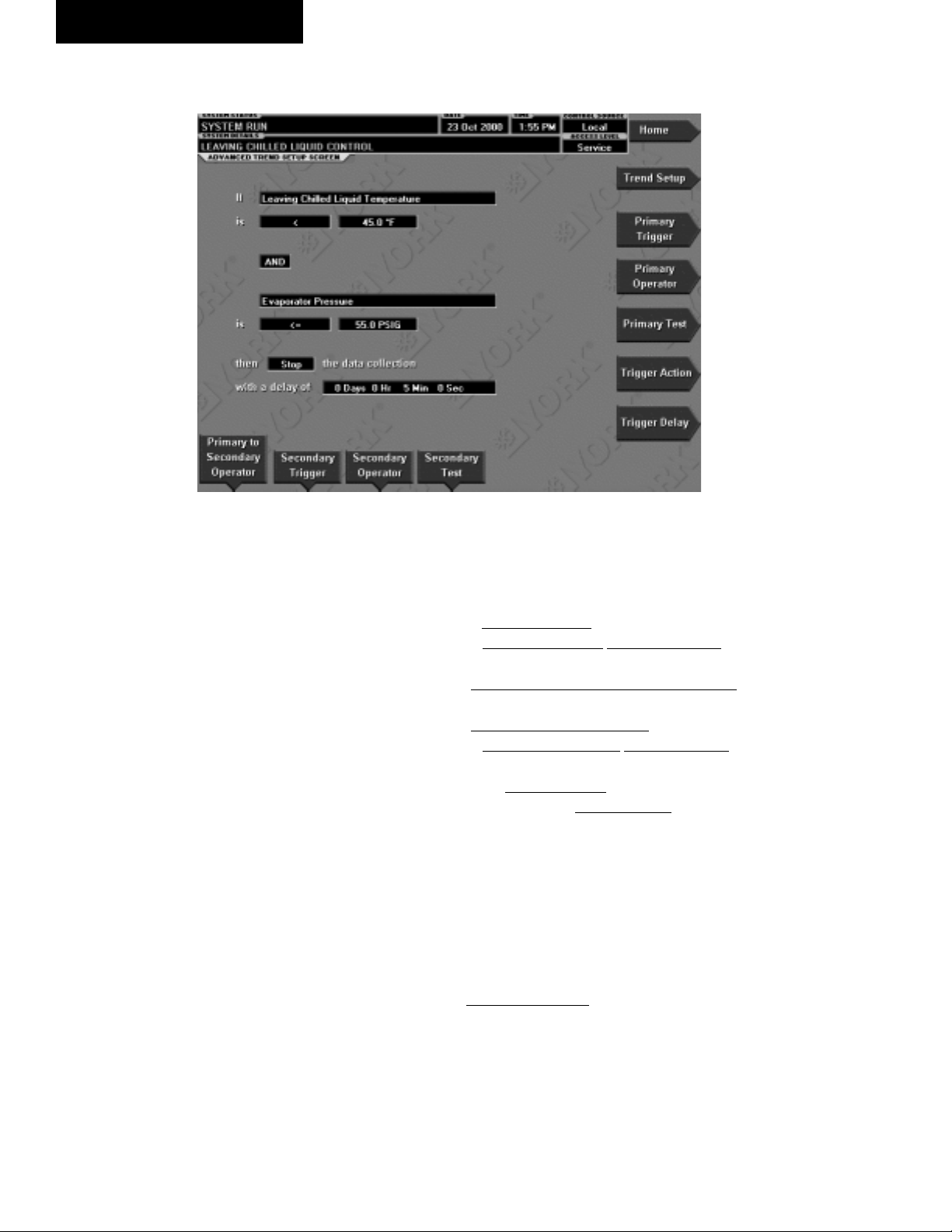
OptiView Control Center
ADVANCED TREND SETUP SCREEN
FORM 160.55-O1 (604)
FIG. 39
OVERVIEW
(Flash Memory Card version C.MLM.02.02.xxx
and later)
The desired data collection start/stop triggers are set up
on this screen. The trend data collection can be set to start
or stop based upon the status of up to two selected Triggers. The Triggers can consist of dig i tal events or analog
parameters compared to thresh olds. The Trig gers can
be used individually or in combination. The digital and
analog parameters are selected from the Common Slots
Screen (or Mas ter Slot Numbers List in this book).
The parameter selected as the Primary Trigger is com pared to a value selected as the Primary Test, using the
Primary Operator as a comparator. If it is eval u at ed as
true, then the data collection is started or stopped (after
any selected Trigger delay) per the selected Trigger
Action.
A Secondary Trigger can be evaluated with the Pri ma ry
Trigger to start/stop data collection. The Pri ma ry to Secondary Operator is used to deÞ ne the Trigger combina-
tions required to be true to start/stop data col lec tion. The
Secondary Trigger is setup and evaluated the same as
the Primary Trigger.
00484VIP
Entry Þ elds are as follows:
If Primary Trigger
Is Primary Operator Primary Test
Primary to Secondary Operator
Secondary Trigger
Is Secondary Operator Secondary Test
Then Trigger Action the Data Collection
With a delay of Trigger Delay
After the desired Triggers are set, the START key on
the TREND Screen must be manually pressed before
the triggers will be evaluated. While waiting for the
trig gers to start or stop data collection, a status message
is displayed in the upper right corner of the TREND
Screen describing the pending action.
DISPLAY ONLY
None
86
YORK INTERNATIONAL
Page 87

FORM 160.55-O1 (604)
PROGRAMMABLE
Primary T rigger
Access Level Required: OPERATOR
Selects the Þ rst parameter to be evaluated. Selection is
made from the Slot Numbers listing on the Trend Com mon Slots Screen or the Master Slot Numbers List in
this book. Setting this slot number to zero disables the
Primary Trigger.
Primary Operator
Access Level Required: OPERATOR
Selects the comparator for the Primary Trigger’s re la tion ship to the Primary Test. If the Primary Trigger is
an analog value, selections are: <, <=, =, =>, >. If the
Primary Trigger is a digital event, selections are: Equal
To, Not Equal To.
Primary Test
Access Level Required: OPERATOR
Selects the value or condition that the Primary Trigger
is compared to. Selection ranges from the Primary Trig ger minimum value to the Primary Trigger maximum
value.
Primary to Secondary Operator
Access Level Required: OPERATOR
Selects whether the Primary Trigger, Secondary Trig ger or both have to be true in order to start or stop data
collection. Selections are AND, OR, XOR and None. If
NONE is selected, the Secondary Trigger is disabled.
Data collection will start/stop (as selected with Trigger
Action) when:
• If AND selected: Both Primary AND Sec ond ary are
true
• If OR selected: Either Primary OR Secondary (or
both) are true
• If XOR selected: Either Primary OR Sec ond ary (but
not both) are true
Secondary T rigger
Access Level Required: OPERATOR
Selects the second parameter to be evaluated. Se lec tion
is made from the Slot Numbers listing on the Trend
Common Slots Screen or the Master Slot Numbers List
in this book. Setting this slot number to zero disables
the Secondary Trigger.
2
T rigger Action
Access Level Required: OPERATOR
Selects whether the trend data collection will Start or
Stop when the Trigger comparisons are true. If set to
Start, data collection will stop after one screen of data
is collected.
Trigger Delay
Access Level Required: OPERATOR
Allows the data collection start or stop to be delayed
after the Triggers evaluate as true. The delay is se lect able from 1 to 864000 seconds (10 days). Display
is in days, hours, minutes and seconds. The delay timer
be gins when the triggers evaluate as true. If the Trigger
Action is set to Start, data collection will begin after the
triggers evaluate as true and the delay timer has elapsed.
If the Trigger Action is set to Stop, data collection will
stop after the Triggers evaluate as true and the delay
timer has elapsed.
Secondary Operator
Access Level required: OPERATOR
Selects the comparator for the Secondary Trigger’s re la tion ship to the Secondary Test. If the Secondary trig ger
is an Analog value, selections are: <, <=, =, =>, >. If
the Secondary Trigger is a digital event, selections are:
Equal To, Not Equal To.
Secondary Test
Access Level Required: OPERATOR
Selects the value or condition that the Secondary Trig ger
is compared to. Selection ranges from the Sec ond ary Trig ger minimum to the Secondary Trig ger max i mum.
NAVIGATION
HOME
Causes an instant return to the Home Screen.
TREND SETUP
Causes an instant return to the Trend Setup Screen.
YORK INTERNATIONAL
87
Page 88

OptiView Control Center
FORM 160.55-O1 (604)
COMMON SLOTS SCREEN
FIG. 40
OVERVIEW
This screen displays the slot numbers of the commonly monitored parameters. The slot numbers for the
re main der of the available parameters are listed on the
Master Slot Numbers List that fol lows.
From these lists, select up to six pa ram e ters to be trend ed.
Return to the Trend Setup Screen and enter the pa ram e ters
Slot Numbers into Data Points 1 through 6.
Re quires a login access level of
OPERATOR or high er.
DISPLAY ONLY
Slot Numbers
These are the slot numbers of the most commonly used
parameters.
00374VIP
PROGRAMMABLE
Page Down
Access Level required: OPERATOR
Scroll down in the displayed data.
Page Up
Access Level Required: OPERATOR
Scroll up in the displayed data.
Print
Access Level Required: OPERATOR
Generates a list of the slot numbers of the available
parameters.
NAVIGATION
Home
Causes an instant return to the Home Screen.
Trend Setup
Causes a return to the Trend Setup Screen.
88
YORK INTERNATIONAL
Page 89

CUSTOM VIEW SCREEN
FORM 160.55-O1 (604)
2
FIG. 41
OVERVIEW
(Flash memory Card version C.MLM.02.01 or later)
This screen allows up to 10 Service Technician se lect ed
parameters to be displayed. These parameters are se lect ed from a list on the Custom View Setup Screen.
This allows the Service Technician to display pa ram e ters
pertinent to a particular problem during trou ble shoot ing.
At completion of the service call, the display can be
cleared or the parameters can be left there for monitoring by operations personnel.
DISPLAY ONLY
None
PROGRAMMABLE
Print
Access Level Required: VIEW
00375VIP
This generates a listing of the parameters displayed on
this screen.
NAVIGATION
Home
Access Level Required: VIEW
Causes an instant return to the Home Screen.
History
Access Level required: VIEW
Causes an instant return to the History Screen.
Setup
Access Level required: SERVICE
Causes a jump to the sub-screen that allows selection of
the parameters to be displayed.
YORK INTERNATIONAL
89
Page 90

OptiView Control Center
FORM 160.55-O1 (604)
CUSTOM VIEW SETUP
FIG. 42
OVERVIEW
(Flash memory Card version C.MLM.02.01 or later)
This screen allows the Service technician to select up to
10 parameters for display on the Custom View Screen.
Requires a login ac cess level of SER VICE. Ser vice Technicians refer to
YORK Ser vice Manual 160.55-M1
for operation in struc tions and ex pla na tion of all programmable setpoints
and dis played values.
DISPLAY ONLY
Slot Numbers
Lists the available parameters that can be displayed.
The desired parameters for display are selected from
this list.
00376VIP
through the Slot Numbers list and note the number of
the parameter(s) to be displayed. Pressing the Select key
places a green colored selection box around Cus tom Slot
1. If it is desired to change an already entered pa ram e ter,
use the 5 and 6 keys to place the selection box around
the slot number to be changed. With the se lec tion box
around the slot number to be changed or en tered, press
the ENTER (!) key. A dialog box is dis played permitting data entry. Using the numeric key pad keys, enter the
desired slot num ber and press the EN TER (!) key.
Custom Slot (1-10)
Use the Select key and numeric keypad keys as de scribed
above and enter the slot number from Slot Num bers
list. Setting the Slot number to zero clears the dis play
of this slot number.
Clear Display
Pressing this key clears all selected parameters from the
Custom View screen.
PROGRAMMABLE
Page Up
Scroll up through list of available parameters.
Page Down
Scroll down through list of available parameters.
Select
First use the Page Up and Page Down keys to scroll
90
NAVIGATION
Home
Access Level Required: VIEW
Causes a return to the Home Screen.
Custom View
Access Level Required: SERVICE
Causes a return to the Custom View Screen.
YORK INTERNATIONAL
Page 91

FORM 160.55-O1 (604)
MASTER SLOT NUMBERS LIST FOR USE WITH TREND FEA TURE
SLOT
NO.
256 System: Chiller State
257 System: Coastdown Time Remaining
258 System: Prelube Time Remaining
259 System: Are Safety Shut down Contacts Closed
260 System: Are Cy cling Shutdown Contacts Closed
261 System: Are An tic i pa to ry Alarm Contacts Closed
262 System: Operating Hours
264 System: Number of Starts
265 System: Is Stop Switch Closed
266 System: Is Start Switch Closed
267 System: Is Remote Ready to Start
280 External Contact: Is Re mote Stop Closed
281 External Contact: Is Re mote Start Closed
282 External Contact: Is MultiUnit Cycling Closed
283 External Contact: Is Re mote Cycling Closed
284 External Contact: Is Aux il ia ry Safety Open
285 Jumper: Is Anti-Recycle Enabled
286 Jumper: Coastdown Operation
287 Jumper: Is Di ag nos tics Enabled
288 Jumper: Liquid Type
289 Jumper: Chilled Liq uid Pump Operation
290 Jumper: Motor Type
291 Jumper: Power Fail ure Restart
292 Jumper: Pre-Run Op er a tion
293 Jumper: Refrigerant Selection
294 Jumper: VSD Motor Sup ply Line Frequency
304 Options: Control Mode
305 Options: System Lan guage
307 Options: Display Mode
512 Sched: Is Schedule Enabled
1280 Pre-Rotation Vanes: Is Motor Switch Closed
1281 Pre-Rotation Vanes: Position
1282 Pre-Rotation Vanes: Are Vanes Opening
1283 Pre-Rotation Vanes: Are Vanes Closing
1284 Pre-Rotation Vanes: Are Vanes Holding
1285 Pre-Rotation Vanes: Control Mode
1296 Discharge: Temperature
1536 Oil: Differential Pressure
1537 Oil: Sump Temperature
1538 Oil Pump: Control Mode
1539 Oil Pump: Is Pump On
1540 Oil Pump: Manual Time Left
DESCRIPTION
SLOT
1792 Leaving Chilled Liquid: Temperature
1793 Leaving Chilled Liquid: Temperature Differential
1794 Leaving Chilled Liquid: Is Flow Switch Closed
1795 Leaving Chilled Liquid: Is Pump On
1796 Leaving Chilled Liquid: Local Temperature Setpoint
1797 Leaving Chilled Liquid: Remote Analog Tem per a ture
1798 Leaving Chilled Liquid: Remote ISN Temperature
1799 Leaving Chilled Liquid: Remote Modem Tem per a ture
1800 Leaving Chilled Liquid: Selected Temperature
1801 Leaving Chilled Liquid: Control Sensitivity
1802 Leaving Chilled Liquid: Remote Temperature
1803 Leaving Chilled Liquid: Restart Temperature Off set
1804 Leaving Chilled Liquid: Restart Temperature
1805 Leaving Chilled Liquid: Shutdown Temperature Off-
1806 Leaving Chilled Liquid: Shutdown Temperature
1807 Return Chilled Liquid: Temperature
1808 Evaporator: Pressure
1809 Evaporator: Saturation Temperature
1810 Evaporator: Small Temperature Difference
1811 Evaporator: Is Refrigerant Sensor Present
1812 Evaporator: Refrigerant Temperature
1813 Evaporator: Delta P / P
1814 Evaporator: Brine Low Cutout
1815 Smart Freeze Protection: Is Control Enabled
1818 Leaving Chilled Liquid: Remote Digital Tem per a ture
2048 Leaving Condenser Liquid: Temperature
2049 Leaving Condenser Liquid: Is Flow Switch Closed
2050 Leaving Condenser Liquid: Is Pump On
2051 Return Condenser Liquid: Temperature
2052 Condenser: Pressure
2053 Condenser: Saturation Temperature
2054 Condenser: Small Temperature Difference
2057 Condenser: Is High Pressure Switch Closed
2058 Condenser: High Pressure Warning Threshold
NO.
DESCRIPTION
Setpoint
Setpoint
Setpoint
Setpoint
Range
Setpoint
set
Setpoint
Setpoint
2
YORK INTERNATIONAL
91
Page 92

OptiView Control Center
FORM 160.55-O1 (604)
SLOT
2059 SubCooling: Temperature
2060 Drop Leg Refrigerant: Is Sensor Present
2061 Drop Leg Refrigerant: Temperature
2063 Vent Line Solenoid: Is Solenoid On
2304 Motor: Starter Type
2305 Motor: Is Motor Starter On
2306 Motor: Current %FLA
2307 Motor: Is Motor Controller Switch Open
2308 Motor: Current Limit Local Setpoint
2309 Motor: Current Limit Remote Analog Setpoint
2310 Motor: Current Limit Remote ISN Setpoint
2312 Motor: Current Limit Selected Setpoint
2313 Motor: Pulldown Demand Time Remaining
2314 Motor: Pulldown Demand Limit Setpoint
2315 Motor: Pulldown Demand Time Setpoint
2316 Motor: Anti-Recycle Time Remaining
2317 Motor: Current Limit Remote Digital Setpoint
Mod "A" SSS ONLY
2560 SSS: Phase A Current
2561 SSS: Phase B Current
2562 SSS: Phase C Current
2563 SSS: Phase A Voltage
2564 SSS: Phase B Voltage
2565 SSS: Phase C Voltage
2566 SSS: Scale/Model
2567 SSS: Full Load Amps
2568 SSS: Supply Voltage Range
2569 SSS: Is Current Unbalance Check Enabled
Mod "B" SSS ONLY
2570 LcSss: Input Power
2571 LcSss: Kilowatt Hours
2572 LcSss: Phase A Current
2573 LcSss: Phase B Current
2574 LcSss: Phase C Current
2575 LcSss: Phase A Voltage
2576 LcSss: Phase B Voltage
2577 LcSss: Phase C Voltage
2578 LcSss: Phase A Temperature
2579 LcSss: Phase B Temperature
2580 LcSss: Phase C Temperature
2581 LcSss: Starter Model
2582 LcSss: Full Load Amps
2583 LcSss: Voltage Range
2584 LcSss: Starting Current
2585 LcSss: Is Serial Communications OK
2586 LcSss: Panel to Sss Comm Errors
2587 LcSss: Sss to Panel Comm Errors
NO.
DESCRIPTION
SLOT
2816 VSD: Motor HP
2817 VSD: 100% Full Load Amps
2818 VSD: Input Power
2819 VSD: Kilowatt Hours
2820 VSD: DC Bus Voltage
2821 VSD: DC Inverter Link Current
2822 VSD: Output Frequency
2823 VSD: Output Voltage
2824 VSD: Phase A Current
2825 VSD: Phase B Current
2826 VSD: Phase C Current
2827 VSD: Is Precharge Relay On
2828 VSD: Is Trigger SCR On
2829 VSD: Is Water Pump On
2830 VSD: Control Mode
2831 VSD: Command Frequency
2832 VSD: Manual Frequency Increment
2833 VSD: Internal Ambient Temperature
2834 VSD: Converter Heatsink Temperature
2835 VSD: Phase A Heatsink Temperature
2836 VSD: Phase B Heatsink Temperature
2837 VSD: Phase C Heatsink Temperature
2838 VSD: Is Communications OK
2839 VSD: Panel to ACC Comms Error Count
2840 VSD: ACC to Panel Comms Error Count
2841 VSD: ACC to VSD Comms Error Count
2842 VSD: VSD to ACC Comms Error Count
2843 VSD: VSD to Filter Comms Error Count
2844 VSD: Filter to ACC Comms Error Count
2845 ACC: Delta P/P
2846 ACC: Stability Limit
2847 ACC: Surge Margin
2848 ACC: Manual Surge Command
2849 ACC: Surge Map Count
2850 ACC: Surge Type
2857 ACC: Surge Map Point Count
2858 ACC: Surge Map Delta P/P
2859 ACC: Surge Map Output Frequency
2860 ACC: Surge Map PRV Position
2861 Filter: Is Filter Installed
2862 Filter: Is Operation Inhibited
2863 Filter: Is Filter Running
2864 Filter: Is Precharge Contactor Closed
2865 Filter: Is Supply Contactor Closed
2866 Filter: Phase Rotation
2867 Filter: Motor HP
2868 Filter: Supply KVA
2869 Filter: Total Power Factor
2870 Filter: DC Bus Voltage
NO.
DESCRIPTION
92
YORK INTERNATIONAL
Page 93

FORM 160.55-O1 (604)
SLOT
2871 Filter: Heatsink Temperature
2872 Filter: L1 - L2 RMS Voltage
2873 Filter: L2 - L3 RMS Voltage
2874 Filter: L3 - L1 RMS Voltage
2875 Filter: L1 - N Peak Voltage
2876 Filter: L2 - N Peak Voltage
2877 Filter: L3 - N Peak Voltage
2878 Filter: L1 Total Harmonic Distortion
2879 Filter: L2 Total Harmonic Distortion
2880 Filter: L3 Total Harmonic Distortion
2881 Filter: L1 RMS Filter Current
2882 Filter: L2 RMS Filter Current
2883 Filter: L3 RMS Filter Current
2884 Filter: L1 RMS Supply Current
2885 Filter: L2 RMS Supply Current
2886 Filter: L3 RMS Supply Current
2887 Filter: L1 Total De mand Distortion
2888 Filter: L2 Total De mand Distortion
2889 Filter: L3 Total De mand Distortion
2890 Filter: Maximum Total Harmonic Distortion
2891 Filter: Maximum Total Demand Distortion
NO.
DESCRIPTION
SLOT
8205 Refrigerant Level: Is Control Enabled
8206 Refrigerant Level: Position
8207 Refrigerant Level: Is Valve Closing
8208 Refrigerant Level: Is Valve Opening
8209 Refrigerant Level: Control Mode
8210 Refrigerant Level: Is Pulldown In Effect
8211 Refrigerant Level: Pulldown Time Remaining
8212 Refrigerant Level: Target Setpoint
8213 Refrigerant Level: Setpoint
8214 Refrigerant Level: Period
8215 Refrigerant Level: Proportional Limit Close
8216 Refrigerant Level: Proportional Limit Open
8217 Refrigerant Level: Rate Limit Close
8218 Refrigerant Level: Rate Limit Open
12288 Purge: Pressure
12289 Purge: Is Air Purge Valve Closed
12290 Purge: Is Oil Purge Valve Closed
12291 Purge: Is Bottom Float Switch Closed
12292 Purge: Is Top Float Switch Closed
12293 Purge: Exhaust Count
12294 Purge: Window Time
12295 Purge: Is High Ef fi cien cy Enabled
12296 Purge: Maximum Purg es Per Hour
NO.
DESCRIPTION
2
2
YORK INTERNATIONAL
93
Page 94

OptiView Control Center
DISPLAY MESSAGES
The Status Bar of the Display contains a Status Line
and, beneath it a Details Line. The Status Line con tains
a message describing the operating state of the chiller;
whether it is stopped, running, starting or shutting down.
The Details Line displays Warning, Cycling, Safety,
Start Inhibit and other messages that provide further
details of the Status Bar messages. The Status Mes sag es
list ed be low are displayed on the Status Line. All other
mes sag es are displayed on the Details Line.
To aid in the meaning of the message, messages are
displayed in different colors as follows:
Normal Operation mes sag es - Green
Warning messages - Yellow
Cycling Shutdown mes sag es - Orange
Safety Shutdown mes sag es - Red
STATUS MESSAGES
“SYSTEM READY TO START”
The chiller is shut down but will start upon receipt of a
Local or Remote start signal.
“CYCLING SHUTDOWN – AUTO RESTART”
The chiller is shut down on a CYCLING shutdown. The
cause of the shutdown is still in effect and is dis played
on the Details line of the Status Bar. The chiller will
au to mat i cal ly restart when the CYCLING con di tion
clears.
“SAFETY SHUTDOWN – MANUAL RESTART”
The chiller is shut down on a SAFETY shutdown. The
cause of the shutdown is still in effect and is displayed
on the Details line of the Status Bar. The chiller can be
started after the Safety condition clears and the Op er a tor
moves the COMPRESSOR switch to the STOP-RESET
(O) position.
“SYSTEM PRELUBE”
A chiller start has been initiated and the pre-start lu bri ca tion is being performed. The Prelube duration is
ei ther 30 seconds or 180 seconds, as conÞ gured with
a Microboard Program Switch. The Pre-lube duration
must nev er be changed by anyone other than a qualiÞ ed Ser vice Tech ni cian. The standard Prelube duration
is 30 sec onds.
“SYSTEM RUN”
The chiller is running under the condition described in
the Details Line of the Status Bar.
94
FORM 160.55-O1 (604)
“SYSTEM COASTDOWN”
The chiller has shut down and the Post-run lubrication is
being performed. On electric motor drive ap pli ca tions,
the Postlube duration is 150 seconds. On Steam Tur bine
applications, it is 15 minutes. The actual du ra tion is de ter mined by a Microboard Program Jumper, con Þ g ured
by a qualiÞ ed Service technician.
“START INHIBIT”
The chiller is prevented from being started due to the
reason displayed on the Details Line of the Status bar.
RUN MESSAGES
“MOTOR – HIGH CURRENT LIM IT”
The Compressor Motor current is > the Local or Re mote
Current Limit Setpoint. The Current Limit Setpoint is
pro grammed over a range of 30 to 100% of the Chill er
Full Load Amps (FLA). When the motor current in creas es to the “inhibit open” threshold, the Pre-rotation
Vanes are inhibited from further opening. This prevents
a fur ther cur rent rise. If the current continues to rise
to the “start close” threshold, the Vanes begin closing
until the current falls to the “stop close” threshold. Au to mat ic Vane operation is resumed and this message
au to mat i cal ly clears when the motor current decreases to
the “allow open” thresh old. The thresholds are dif fer ent
for the var i ous motor start er applications. To allow Þ eld
calibration of the Solid State Starter (Mod “A”) Logic
Board or CM-2 Current Module, pressing the Slide Valve
Load key in Service access level, starts a 10 minute timer
during which the current limit thresh olds are elevated.
Refer to table on next page.
Vane Control
Electro-Me chan i cal/
Solid state starter
On rise, inhibit open 100 100 107
On fall, allow open 98 98 106
On rise, start close 104 103 110
On fall, stop close 102 101 109
An example of current limit is as follows: If a Solid Sate
Starter chiller FLA is 100 Amps and the Current Limit
Setpoint is 50%, the following will occur:
50 Amps – inhibit vane open
52 Amps – vanes begin closing
51 Amps – vanes stop closing
49 Amps – allow automatic vane control
“LEAVING CHILLED LIQUID CONTROL”
The chiller is running, controlling the Leaving Chilled
Liq uid to the Leaving Chilled Liquid Temperature
Setpoint. There are no system conditions inhibiting
this operation.
Motor Current (%FLA)
VSD Ser vice Mode
YORK INTERNATIONAL
Page 95

FORM 160.55-O1 (604)
“MOTOR PULLDOWN LIMIT”
The Pulldown Demand Limit Setpoint timer is in ef fect
and the Compressor Motor current is > the Pulldown
Demand Current Limit Setpoint value. The Pre-rotation
vane operation is being inhibited as de scribed in “ MO TOR – HIGH CURRENT LIMIT” message above.
START INHIBIT MESSAGES
“ANTI-RECYCLE XXMin/Sec”
The chiller is inhibited from starting because the 30
minute anti-recycle time has not yet elapsed. Time re main ing is displayed.
“VANE MOTOR SWITCH OPEN”
The chiller is inhibited from starting because the Prerotation Vanes are not fully closed.
“MOTOR CURRENT >15% FLA”
The OptiView Control Center has detected a Com pres sor Motor Current of a magnitude that is >15% of
the chiller Full Load Amps for 10 continuous seconds,
while the chiller is shutdown. As long as this condition ex ists, the oil pump is turned on. This is generally
in dic a tive of a failure of the motor starter, Control
Cen ter start cir cuits or motor current feedback circuits.
After motor current is no long er detected, a SYS TEM
COASTDOWN is per formed. The chiller can be start ed
after motor current is no long er detected, the SYS TEM
COASTDOWN has com plet ed and the COM PRES SOR
switch is placed in the STOP-RE SET (O) po si tion.
“LCSSS – HIGH TEMPERATURE PHASE X
– STOPPED”
(Mod. “B” Solid State Starter only)
The chiller is stopped and the Liquid Cooled Solid
State Starter Logic/Trigger Board has detected that the
tem per a ture of phase A, B or C (designated as X in the
message) Silicon Controlled RectiÞ er (SCR) module is
>110°F. The starter cooling pump will run and the chill er
will be inhibited from starting until the tem per a ture de creas es to <109°F.
WARNING MESSAGES
“WARNING – REAL TIME CLOCK FAILURE”
During the initialization process that occurs when pow er
is applied to the OptiView Control Center, test data is
written to a location in the BRAM battery backed mem o ry device (IC location U52 on Microboard). This data
is then read from the BRAM and compared to the test
data. If the read data is not the same as that which was
written to the device, it is assumed the BRAM and Real
time Clock operation is defective and this mes sage is
dis played. The BRAM should be replaced by a qualiÞ ed
Service Technician. This message au to mat i cal ly clears
when the BRAM problem has been solved.
“WARNING – CONDENSER OR EVAP O RA TOR
XDCR ERROR”
The Evaporator pressure Transducer is indicating a high er
pressure than the Condenser pressure Trans duc er after the
chiller has been running for 10 minutes. This is in dic a tive
of a Condenser or Evaporator Trans duc er fail ure. This
message will be displayed until the condition clears and
the WARNING RESET Keypad key is pressed on the
home screen in OPERATOR (or high er) ac cess mode.
Condition not checked in Brine mode.
“WARNING – SETPOINT OVERRIDE”
A blank BRAM battery-backed memory device (IC
lo ca tion U52 on Microboard) or a failure of this device
was detected during the initialization process that oc curs when power is applied to the OptiView Control
Center. Due to this failure, any or all of the pro grammed
Setpoints could have been corrupted. Therefore, all Setpoints have been automatically changed to their Default
val ues. All Setpoints will have to be pro grammed to
their de sired values. This message will clear when the
WARN ING RESET key is pressed on the home screen
in OP ER A TOR (or high er) access mode.
“WARNING – CONDENSER – HIGH PRES SURE
LIMIT”
The Condenser Pressure exceeds the High Pressure
Warning Setpoint threshold, programmed by a Service
technician logged in at SERVICE access level. While
this condition is in effect, the Pre-rotation Vanes are
inhibited from further opening. This message au to mat i cal ly clears and the Vanes are permitted to open
when the Condenser pressure decreases to 0.1 PSIA
be low the Setpoint.
“W ARNING – EVAPORAT OR – LOW PRES SURE
LIMIT”
The Evaporator pressure has decreased to the Warn ing
threshold. This threshold is Þ xed in Water cooling ap pli -
ca tions. In Brine cooling applications, the thresh old is a
Þ xed amount above the programmable safety shut down
threshold. The Safety threshold in Brine ap pli ca tions is
determined by the Brine solution and is de ter mined by
the YORK Factory. While this condition is in effect,
the Pre-rotation Vanes are inhibited from fur ther open-
2
YORK INTERNATIONAL
95
Page 96

OptiView Control Center
FORM 160.55-O1 (604)
ing. This message automatically clears and the Vanes
are permitted to open when the Evap o ra tor pres sure
in creas es to the reset value.
Warning Threshold (PSIA) Reset Thresh old (PSIA)
Water Brine Wa ter Brine
R11 5.5 0.1 >Safety Setpoint 5.6 0.3>Safety Setpoint
R123 4.5 0.1 >Safety Setpoint 4.7 0.3>Safety Setpoint
“WARNING – VANES UNCALIBRATED – FIXED
SPEED”
The Compressor Motor Variable Speed Drive (VSD) is
operating Fixed Speed (full speed) mode because the
Pre-rotation Vanes position potentiometer calibration
has not been performed. Message automatically clears
when calibration has been performed.
“WARNING – HARMONIC FILTER –
OPERATION INHIBITED”
The compressor Motor variable Speed Drive (VSD) Har mon ic Filter has been inhibited. Refer to VSD Ser vice
manual 160.00-M1. Harmonic Þ lter operation should not be
altered by anyone other than a qualiÞ ed Service tech ni cian.
Message automatically clears when Þ lter is en abled.
“WARNING – HARMONIC FILTER –
DATA LOSS”
Communications between the Harmonic Filter Logic Board
and the Compressor Motor Variable Speed Drive (VSD)
Logic Board or the Adaptive Capacity Control Board is not
occurring. While this condition exists, all Fil ter related pa ram e ters are displayed as X’s. This mes sage au to mat i cal ly
clears when communications are re stored.
“WARNING – HARMONIC FILTER –
INPUT FREQUENCY RANGE”
The power line frequency detected by the Compressor
motor Variable Speed Drive (VSD) Harmonic Filter is
outside the range of 58 to 62 Hz (60 Hz) or 49 to 51 Hz
(50 Hz). While this condition exists, all Filter related pa ram e ters are displayed as X’s. This message au to mat i cal ly
clears when the line frequency is within range.
“WARNING – PURGE – HIGH PRESSURE”
With the chiller running, the purge pressure in creased to
>55.0 PSIA (standard purge units) or > 95.0 PSIA (high
efÞ ciency purge units) con tin u ous ly for 4 min utes. This
message will be displayed until the purge pressure de creas es
to the reset threshold of <
<
95.0 PSIA (high efÞ ciency purge units) or the chiller is
55.0 PSIA (stan dard purge units),
not running and the WARN ING RESET key is pressed on
the HOME Screen is OP ER A TOR (or high er) access mode.
This warning will not be dis played if the Purge Float Switch
Error warn ing (below) is in ef fect.
“WARNING – PURGE – FLOAT SWITCH ER ROR”
With the chiller running, the Purge Float Switches were
in invalid states. Typically this is caused by the Bottom
Float Switch being in the closed position and the Top
Float Switch in the open position, indicating the oil lev el
is si mul ta neous ly below the bottom switch and above
the top switch, an impossible condition. This message
will be displayed until the ß oat switches are in di cat ing
valid positions (or the chiller is not run ning) and the
WARNING RESET key is pressed on the HOME
Screen in OPERATOR (or high er) access mode. While
this message is displayed, the Purge Oil Solenoid Valve
is de-energized, draining the Purge Tank.
“WARNING – EXCESS PURGE”
The purge EXHAUST COUNT has equaled the pro grammed MAXIMUM PURGES PER HOUR set point.
While this message is displayed, purging continues but
the EXHAUST COUNT is not incremented. Clearing
this message resets the ex haust count and exhaust win dow. If the chiller is run ning, the exhaust window will
then in cre ment from 0 to 60 minutes and the exhaust
count will increment as ex hausts occur. This message
will be displayed until the WARNING RESET key is
pressed on the HOME Screen in OPERATOR (or high er)
access mode.
“WARNING – PURGE – CANISTER #1 FULL”
(Flash Memory Card version C.MLM.02.02.xxx
and later)
The Purge Canister Alarm on the Lower Emis sions Purge
Canister #1 indicates the canister has captured its ca pac i ty
of refrigerant. The can is ter must be re placed fol low ing
instructions on label inside Purge Panel door. This message is trig gered when the Purge Canister Alarm output
increases to >
until the Alarm signal is <
2.20VDC. This message will be displayed
0.90VDC and the WARNING
RESET key is pressed on the HOME Screen in OPERATOR (or higher) access mode.
“WARNING – VANES UNCALIBRATED”
The Hot Gas Bypass feature is enabled, but the Pre-rotation Vanes calibration procedure has not yet been performed. Message automatically clears when cal i bra tion
has been performed.
“WARNING – EXTERNAL I/O – SERIAL COM MU NI CA TIONS”
Serial communications between the Microboard and the
optional Analog I/O Board has been interrupted for at
least 20 seconds. Message automatically clears when
communications are restored.
96
YORK INTERNATIONAL
Page 97

FORM 160.55-O1 (604)
“WARNING – REFRIGERANT LEVEL OUT OF
RANGE”
(Flash Memory Card version C.MLM.02.02C.xxx
and earlier)
The output of the Condenser Refrigerant Level Sensor is
> 5.1VDC. This is indicative of a Level Sensor fail ure.
While this condition exists, the Refrigerant Vari able Or i Þ ce is driven to the full open po si tion. This mes sage
au to mat i cal ly clears when the Refrigerant Level sensor
out put is within range.
“WARNING - EXCESS SURGE DE TECT ED”
(Flash Memory Card version C.MLM.02.02.xxx
and later)
(Applies only if Surge Protection SHUTDOWN fea ture
is Disabled.) The Surge Window Count has ex ceed ed
the Count Lim it. Message can be manually cleared
after the Surge Win dow Count is <
the SHUT DOWN fea ture is Enabled or the chill er is
stopped. To clear mes sage press WARNING RE SET
key on HOME Screen when logged in at OP ER A TOR
(or higher) access lev el.
“WARNING – SURGE PROTECTION – EX CESS
SURGE LIMIT”
(Flash Memory Card version C.MLM.02.02.xxx
and later)
(Applies only if Surge Protection EXTENDED RUN
feature is Enabled.) Displayed during the Surge Pro tec tion 10 minute Ex tend ed Run period. This period begins
when the Surge Window Count exceeds the Count Lim it.
During this period, the Pre-rotation Vanes are driv en
closed. When 10 minutes have elapsed, this mes sage
and the Pre-rotation Vanes load inhibit are au to mat i cal ly
cleared. Message and load inhibit are also cleared when
the chill er is shutdown.
the Count Limit,
If the optional Hot Gas Bypass fea ture
is en abled, the valve position must be
at 100% be fore the Ex tend ed Run is
im ple ment ed. If the chiller is chill er is
equipped with a compressor motor Vari able Speed Drive, the output fre quen cy
must be at full speed (50 Hz/60 Hz) be fore this con trol can be im ple ment ed.
ROUTINE SHUTDOWN MES SAG ES
“REMOTE STOP”
A shutdown command has been received from a re mote device. Remote Stop commands can be received
in Dig i tal Remote mode via I/O Board TB4-7/8 or in
ISN (In te grat ed Systems Network) Remote mode via
the MicroGateway serial com mu ni ca tions.
“LOCAL STOP”
A local shutdown command has been received by plac ing the Keypad Start-Run-Stop/Reset Switch in the stop
(O) position.
“PLACE COMPRESSOR SWITCH IN RUN PO-
SI TION”
The OptiView Control Center is in either Digital or ISN
(In te grat ed Systems Network) Remote mode. The Op er a tor is requested to place the COMPRESSOR Switch
in the RUN position. The OptiView Control Center
will not ac cept a Remote start/stop command unless
the switch is in the RUN position.
CYCLING SHUTDOWN MESSAGES
“MULTIUNIT CYCLING – CONTACTS OPEN”
The Multiunit Cycling contacts connected to I/O Board
TB4-9, have opened to initiate a cycling shutdown. The
chiller will automatically restart when the contacts close.
“SYSTEM CYCLING – CONTACTS OPEN”
The System Cycling contacts connected to I/O Board
TB4-13, have opened to initiate a cycling shutdown.
The chiller will automatically restart when the contacts
close.
“OIL – LOW TEMPERATURE”
The oil temperature has decreased to < 55°F. The chill er
will automatically restart when the temperature in creas es
to > 71.0°F.
“CONTROL PANEL – POWER FAILURE”
A Control Power failure has occurred. If the power
fail ure occurred while the chiller was running, it will
au to mat i cal ly restart when power is restored. How ev er,
if the power failure duration was < the duration of the
ap pli ca ble “Coastdown” period (2.5 minutes standard;
15 minutes steam turbine) when power is restored, the
re main der of the “Coastdown” will be performed, prior
to the chiller starting. This mes sage can indicate a Cy cling (auto-restart after power failure) or Safety (man u al
re start after power failure) shutdown, depending upon
OptiView Con trol Center con Þ g u ra tion. It indicates a
cycling shut down when displayed in orange characters;
Safety shut down when displayed in red characters. The
OptiView Control Center is conÞ gured for auto-restart
or manual restart after power failure by a qualiÞ ed Ser-
vice Technician following in struc tions in YORK Ser vice
Manual 160.55-M1.
2
YORK INTERNATIONAL
97
Page 98

OptiView Control Center
FORM 160.55-O1 (604)
“LEAVING CHILLED LIQUID – LOW
TEMPERATURE”
The Leaving Chilled Liquid Temperature has de creased
to the programmed Shutdown Temperature Setpoint. The
chiller will automatically restart when the tem per a ture
increases to the programmed Restart Tem per a ture
Setpoint.
“LEAVING CHILLED LIQUID –
FLOW SWITCH OPEN”
The Chilled Liquid Flow Switch has remained open for
2 continuous seconds while the chiller was running or
failed to close during the System Pre-lube period. The
chiller will automatically restart when the ß ow switch
closes.
“CONDENSER – FLOW SWITCH OPEN”
The Condenser water ß ow switch has remained open for
2 continuous seconds while the chiller was run ning. This
check is bypassed for the Þ rst 30 seconds of “Sys tem
Run”. The chiller will automatically restart when the
ß ow switch closes.
“MOTOR CONTROLLER –
CONTACTS OPEN”
The CM-2 Current module (Electromechanical starter
applications) or Solid State Starter Logic Board (Mod
“A” Solid State Starter applications) has shutdown the
chill er. When detecting a fault condition that places the
starter or motor at risk, these devices open the Mo tor
Con trol ler contacts “CM” (located on the re spec tive device and connected between TB6-16 and TB6-53 in the
OptiView Control Center) to initiate a shutdown. Since
there are several different faults that are mon i tored,
LED’s on the respective device illuminate to iden ti fy
the spe ciÞ c fault that has occurred. Refer to YORK
Manual 160.46-OM3.1 for details of Mod “A” Solid
State Start er initiated shut downs and 160.55-M1 for
CM-2 initiated shut downs. The chiller will au to mat i cal ly
re start when the Motor Controller contacts close. On
some shut downs, the re spec tive device au to mat i cal ly
closes the con tacts when the fault condition clears. Other
shut downs re quire the Operator to perform a Manual
Reset at the respective device.
Device Manual Reset Fault Automatic Re set Fault
CM-2 Module Overload None
Overload Phase Rotation/Loss
Solid State Starter High Temp(>212°F) High Temp start inhibit (>110°F)
Fault Current Trigger Board Out-of-Lock
“MOTOR CONTROLLER – LOSS OF
CURRENT”
The Compressor Motor current decreased to 10% Full
Load Amps (FLA) for 25 continuous seconds while the
chiller was running. This could be caused by the starter
de-energizing during run or a defect in the motor cur rent feedback circuitry to the OptiView Control Cen ter.
The chill er will automatically restart at the com ple tion
of “System Coastdown”.
“POWER FAULT”
The CM-2 Current Module (Electro-mechanical start er
applications) or Solid State Starter Logic Board (Mod
“A”) (Solid State Starter applications) has shutdown the
chill er be cause it detected a fault condition that plac es
the motor at risk. These devices open and close the Motor con trol ler “CM” contacts (located on the re spec tive
device and connected between TB6-16 and TB6-53 in
the OptiView Control Center) in < 3 sec onds to initiate
the shutdown and produce this mes sage. An LED on
the respective device illuminates to iden ti fy the spe ciÞ c fault that has occurred. Refer to YORK Manual
160.46-OM3.1 for de tails of Mod “A” Solid State Start er
ini ti at ed shut downs and 160.55-M1 for CM-2 initiated
shut downs. The chiller will au to mat i cal ly restart when
the contacts close.
Device Shutdown
CM-2 Module Power fault
Solid State Starter Pow er Fault
Half Phase
“CONTROL PANEL – SCHEDULE”
The programmed Daily Schedule Setpoint has shut down
the chiller. The chiller will automatically re start at the
next scheduled start time.
“STARTER – LOW SUPPLY LINE VOLTAGE”
(Mod “A” Solid State Starter”)
The voltage in any phase of the AC Power Line Volt age
supplying the Solid State Starter has decreased to the low
line voltage threshold for 20 continuous sec onds. The
chiller will automatically restart when the voltage returns
to the restart level. The thresholds are as follows:
Supply Voltage Range (Volts) Shutdown (Volts) Restart (Volts)
380 305 331
400 320 349
415 335 362
440-480 370 400
550-600 460 502
Supply Voltage Range disabled none N/A
98
YORK INTERNATIONAL
Page 99

FORM 160.55-O1 (604)
“STARTER – HIGH SUPPLY LINE VOLTAGE”
(Mod “A” Solid State Starter”)
The voltage in any phase of the AC Power Line Volt age
supplying the Solid State Starter has increased to the
high line voltage threshold for 20 continuous sec onds.
The chiller will automatically restart when the voltage
returns to the restart level. The thresholds are as follows:
Supply Voltage Range (Volts) Shutdown (Volts) Restart (Volts)
380 415 414
400 436 435
415 454 453
440-480 524 523
550-600 655 654
Supply Voltage Range disabled none N/A
MOD “B” SOLID STATE STARTER
CYCLING SHUT DOWN MES SAG ES
“LCSSS – INITIALIZATION FAILED”
When AC Power is restored to the system after a pow er
failure, an initialization process occurs wherein the
OptiView Con trol Center attempts to establish com mu ni ca tions through the serial communications link with
the Liquid Cooled Solid State Starter. If com mu ni ca tions
are not es tab lished within 10 consecutive at tempts, a
Cycling shut down is performed and this message is
displayed. The Control Center attempts to establish
com mu ni ca tions un til suc cess ful.
“LCSSS – SERIAL COMMUNICATIONS”
After communications have been successfully es tab lished in the INITIALIZATION process, the OptiView
Control Center initiates a data transmission to the Liq uid
Cooled Solid State Starter on the serial com mu ni ca tions
link every 2 seconds. After these com mu ni ca tions have
been established, if the Control Center does not receive
a reply within 10 consecutive attempts, a Cy cling shut down is performed and this message is dis played. This
same Cycling shutdown is performed, along with the
same message, if the Liquid Cooled Sol id State Starter
does not receive a response from the con trol center
after 10 consecutive attempts to com mu ni cate with the
Control Center after INITIALIZATION has been suc cess ful ly completed. The Control Center at tempts to
es tab lish communications until successful.
“LCSSS SHUTDOWN – REQUESTING FAULT
DATA . . .”
The Liquid Cooled State Starter Logic/Trigger Board
has shut down the chiller but the OptiView Control
Cen ter has not yet received the cause of the fault from
the LCSSS, via the serial communications link. The
LCSSS shuts down the chiller by opening the Motor
Controller LCSSS Stop Contacts (K1 relay located on
the start er Logic/Trig ger Board and connected between
TB6-16 and TB6-53 in the OptiView Control Center).
The Microboard, in the Control Center then sends a
request for the cause of the fault to the Logic/Trigger
Board over the serial com mu ni ca tions link. Since serial
com mu ni ca tions are initiated every 2 seconds, this mes sage is typically displayed for a few seconds and then
re placed with one of the below listed fault messages.
“LCSSS – STOP CONTACTS OPEN”
Refer to “LCSSS SHUTDOWN – REQUESTING
FAULT DATA ...” above. If the OptiView Control
Cen ter’s Microboard does not receive the cause of
a starter initiated shutdown with 20 seconds of the
shut down, it is as sumed it is not forthcoming and that
mes sage is re placed with this message. The chiller can
be started when the Motor Controller LCSSS Stop
Con tacts close.
A missing interlock jumper between Start er Log ic/Trig ger
Board J1-1 and J1-12 will also produce this mes sage.
“LCSSS – POWER FAULT”
The Liquid Cooled Solid State Starter Logic/Trigger
Board has detected that the compressor motor current in
one or more phases has decreased to <10% of the FLA
for a minimum of 1 line cycle. This check is in hib it ed
during the Þ rst 4 seconds of SYSTEM RUN and until
the motor current is >25% of the FLA. The chiller will
automatically restart upon completion of SYSTEM
COASTDOWN.
“LCSSS – LOW PHASE X TEMPERATURE SEN SOR”
The Liquid Cooled Solid State Starter Logic/Trigger
Board has detected that the temperature of the starter
phase A, B or C (designated as X in the message) Sil i con
Controlled RectiÞ er (SCR) Module has decreased to
<37°F. This would generally be indicative of a dis con nect ed or defective sensor. If all three SCR Mod ules
are indicating a temperature of <37°F, the SCR Module
cooling pump turns on. This is accomplished by disconnecting all three sensors. This feature allows Ser vice
Technicians to run the cooling pump while Þ ll ing the
cooling system by disconnecting plugs P2, P3 and P4
in the LCSSS.
“LCSSS – RUN SIGNAL”
The Liquid Cooled Solid State Starter receives two
start signals from the OptiView Control Center si mul -
2
YORK INTERNATIONAL
99
Page 100

OptiView Control Center
FORM 160.55-O1 (604)
ta neous ly; one via the serial communications link and
one via the start re lay TB6-24 in the OptiView Control
Cen ter. If they are not re ceived within 5 seconds of
one another, a cycling shut down is performed and this
mes sage is displayed. This is generally indicative of
de fec tive wiring.
“LCSSS – INVALID CURRENT SCALE
SELECTION”
There is an invalid compressor motor current scale
jump er combination installed in the Liquid Cooled
Sol id Starter Logic/Trigger Board J1. Jumper combination determines allowable “100% FLA” setpoint range;
7L-35 to 260A, 14L-65 to 510A, 26L-125 to 850A and
33L-215 to 1050A. The chiller will be permitted to
start when the jumpers are conÞ gured correctly. Refer
to YORK Starter service manual 160.00-O2 for valid
jump er con Þ g u ra tions.
“LCSSS – PHASE LOCKED LOOP”
The Liquid Cooled Solid State Starter Logic/Trigger
Board phase locked loop circuit was not able to main tain lock with phase A of the power line. This could be
caused by a power line anomaly such as sag or jitter. A
power line frequency jitter of up to 3 Hz/second can be
tolerated. The chiller will automatically restart when
lock has resumed.
“LCSSS – LOW SUPPLY LINE VOLTAGE”
The Liquid Cooled Solid State Starter Logic/Trigger
Board has detected that the compressor motor AC
pow er line voltage, in any phase, decreased below the
low line voltage threshold continuously for 20 seconds.
The chill er will automatically restart when the voltage
in all phases returns to the restart level. The thresholds
are as follows:
Supply Voltage Range (Volts) Shutdown(Volts) Restart(Volts)
Disabled None N/A
200-208 160 174
220-240 185 200
380 305 331
400 320 349
415 335 362
440-480 370 400
550-600 460 502
“LCSSS – HIGH SUPPLY LINE VOLTAGE”
The Liquid Cooled Solid State Starter Logic/Trigger
Board has detected that the compressor motor AC pow er
line voltage, in any phase, exceeded the high line volt age
thresh old continuously for 20 seconds. The chiller will
automatically restart when the voltage in all phases re turns
to the restart level. The thresholds are as follows:
Supply Voltage Range (Volts) Shutdown(Volts) Restart(Volts)
Disabled None N/A
200-208 227 226
220-240 262 261
380 415 414
400 436 435
415 454 453
440-480 524 523
550-600 655 654
“LCSSS – LOGIC BOARD PROCESSOR”
Communication between the V25 Microprocessor and
Digital Signal Processor (DSP) on the Liquid Cooled
Solid State Starter Logic/Trigger Board has been in ter rupt ed. The chiller will automatically restart when
com mu ni ca tions are restored.
“LCSSS - PHASE LOSS”
(Flash Memory Card version C.MLM.02.01 or
later)
The Liquid Cooled Solid State Starter Logic/Trigger
Board has detected the line-to-line RMS voltage in any
phase has decreased to <
30% of the lowest value of the
programed voltage range. If the pro grammed volt age
range is “Disabled”, a value of 60VAC is used as the
threshold. The chiller will automatically restart when the
line voltage is > the shutdown threshold. The volt age
range is pro grammed by a Service technician fol low ing
in struc tions in Service Manual 160.55-M1.
“LCSSS – PHASE ROTATION/LOSS”
(Flash Memory Card version C.MLM.02.00 only)
The Liquid cooled Solid State Starter Logic/Trigger
Board has detected that the three-phase compressor
motor power line voltage phase rotation is not correct
or the line-to-line voltage in any phase has decreased to
<30% of nominal. The chiller will automatically re start
when the power line conditions are acceptable.
“LCSSS – LOGIC BOARD POWER SUPPLY”
Following application of power, this message is dis played and a snapshot of the LCSSS parameters and
time of power failure are sent to the OptiView Control
Center.
COMPRESSOR MOTOR VARIABLE
SPEED DRIVE:
CYCLING SHUTDOWN MESSAGES
The following Cycling shutdown messages are dis played
on Compressor Motor Variable Speed Drive (VSD) applications only. These messages are gen er at ed by events
that occur within the VSD. The chiller will au to mat i cal ly
100
YORK INTERNATIONAL
 Loading...