

Page 1
TECHNICAL GUIDE
MODELS: MV
MODULAR VARIABLE SPEED AIR HANDLERS
FOR USE WITH SPLIT SYSTEM
COOLING & HEAT PUMP
1200 - 2000 CFM BLOWERS
3 - 5 TON COILS
OPTIONAL 1 & 3
ELECTRIC HEATERS
Due to continuous product improvement,
specifications are subject to change without notice.
Visit us on the web at:
www.york.com
Additional rating information can be found at:
www.ahridirectory.org
ISO 9001
Certified Quality
Management System
550569-YTG-D-1212
DESCRIPTION
This unique modular system allows the flexibility to handle an y
application. These versatile coils and blowers may be used for
upflow, downflow, or horizontal left or right applications. They
may be combined to function as a cooling only unit or with a
heat pump including electric heat for 1 and 3 phase applications. The blower and electric heater could be used as stand
alone electric furnaces.
FEATURES
Blowers - Models to match any air flow or voltage requirement.
The compact size allows easy installation. Blowers are sized to
deliver design air quantity both efficiently and quietly. The
motors provide a selection of air quantities to match any a pplication. All models include a one-minute blower off delay as
standard to enhance system efficiency ratings. The durable,
pre-painted steel protects the unit against rust and corrosion. All
models have 1 inch foil face fiber glass insulation, prov iding a
thermal insulation value of R-4.2.
Coils - Staggered rows of rifled copper tubes are mechanically
expanded into enhanced surface aluminum fins to provide high
heat transfer and long-lasting quality. The MC multi-position
coils may be used for upflow, downflow, and horizontal left or
right applications. Coil cabinets are insulated with 3/4" fo il face
insulation to prevent sweating.
Thermal Expansion Valves - Coils are ordered as “Flex-coil”
unit without a factory installed mertering device. Flex-coil models allow for field installed R-22 or R-410A TXV’s for added flexibility to meet refrigerant system choice.
Electric Heaters - Both single and three phase electri c heater
models are available to match any requirement. All heaters
include nickel-chromium elements with a 5-year limited warranty on 1 Ø heating elements and 1 yea r li mi ted w arranty o n 3
Ø heating elements. Sequential operation is provided to control
heaters in all models. Circuit breakers are used in 208/230 volt,
single-phase heaters of 15 KW and larger.
Models equipped with circuit breakers may be altered in the
field to use multi-source power supply. Over-temperature limit
switches provide protection fro m ai rfl o w lo ss w it h fu si bl e li nk
backup protection.
Communication - These models may be connected as part of
a communciations system using a 4-wire connection bus.
Accessories - A full line of matching accessories available for
use with the blower and coils to allow any type application.
LIMITATIONS
These units must be wired and installed in accordance with all
national and local safety codes.
Voltage limits are as follows:
AIR HANDLER VOLTAGE
208/230-1-60 187 - 253
* Rated in accordance with ARI Standard 110, utilization range “A”.
Air flow must be within the minimum and maximum limits approved for electric
heat, evaporator coils and outdoor units.
NORMAL OPERATING
VOLTAGE RANGE*
FOR DISTRIBUTION USE ONLY - NOT TO BE USED AT POINT OF RETAIL SALE
Page 2
550569-YTG-D-1212
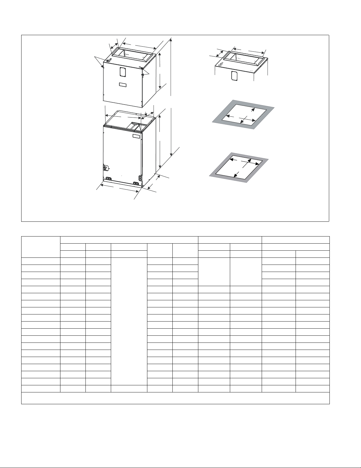
AIR HANDLER
MA / MV
COIL
MC
21.5”
B
A
C
(TOTAL HEIGHT)
E
20-3/8”
J
K
A
E
10-3/8”
10-3/8”
E
D
20-1/4”
D
20-1/2”
AIR HANDLER TOP (All Models)
AIR HANDLER BOTTOM OPENING
COIL BOTTOM OPENING
NOTE: Power wiring may be brought into the unit through one of the knockouts in either the top or the left side panel.
Multiple knockouts are provided to accommodate all of the electric heat and transformer accessories that are available.
Use the knockouts that provide the best wire routing for the accessory being used.
DIMENSIONS - (BLOWER WITH MC COILS)
DIMENSIONS
Dimensions Wiring K.O.’s
Model
MV12B 25 17.5
MV12D 25 24.5 23.5 21-19/32 – –
MV16C 25 21 20 18-3/32 – –
MV20D 25 24.5 23.5 21-19/32 – –
MC18B3XC1 22 17.5 16.5 16 3/8 – – 3/8 3/4
MC24B3XC1 26.5 17.5 16.5 16 3/8 – – 3/8 3/4
MC30B3XC1 26.5 17.5 16.5 16 3/8 – – 3/8 3/4
AB C
Height Width Total Height Power Control Liquid Vapor
DE
16.5 14-19/32
JK Line Size
7/8" (1/2")
1-3/8" (1")
1-23/32" (1-
1/4")
MC35B3XC1 22 17.5 16.5 16 3/8 – – 3/8 3/4
MC35C3XC1 22 21 20 19 7/8 – – 3/8 3/4
MC36B3XC1 26.5 17.5 16.5 16 3/8 – – 3/8 7/8
MC36C3XC1 26.5 21 20 19 7/8 – – 3/8 7/8
MC42B3XC1 32 17.5 16.5 16 3/8 – – 3/8 7/8
MC42C3XC1 32 21 20 19 7/8 – – 3/8 7/8
MC43B3XC1 26.5 17.5 16.5 16 3/8 – – 3/8 7/8
MC43C3XC1 26.5 21 20 19 7/8 – – 3/8 7/8
MC48C3XC1 32 21 20 19 7/8 – – 3/8 7/8
47 to 57
Depending
on combination
MC48D3XC1 32 24.5 23.5 23 3/8 – – 3/8 7/8
MC60D3XC1 32 24.5 23.5 23 3/8 – – 3/8 7/8
MC62D3XC1 36 24.5 61 23.5 23 3/8 – – 3/8 7/8
All MC coils include a factory installed horizontal drain pan.
(3X) = Models require field installed metering device.
1. Parenthesis indicate conduit size.
1
7/8" (1/2")
Refrigerant Connections
––
2 Johnson Controls Unitary Products
Page 3
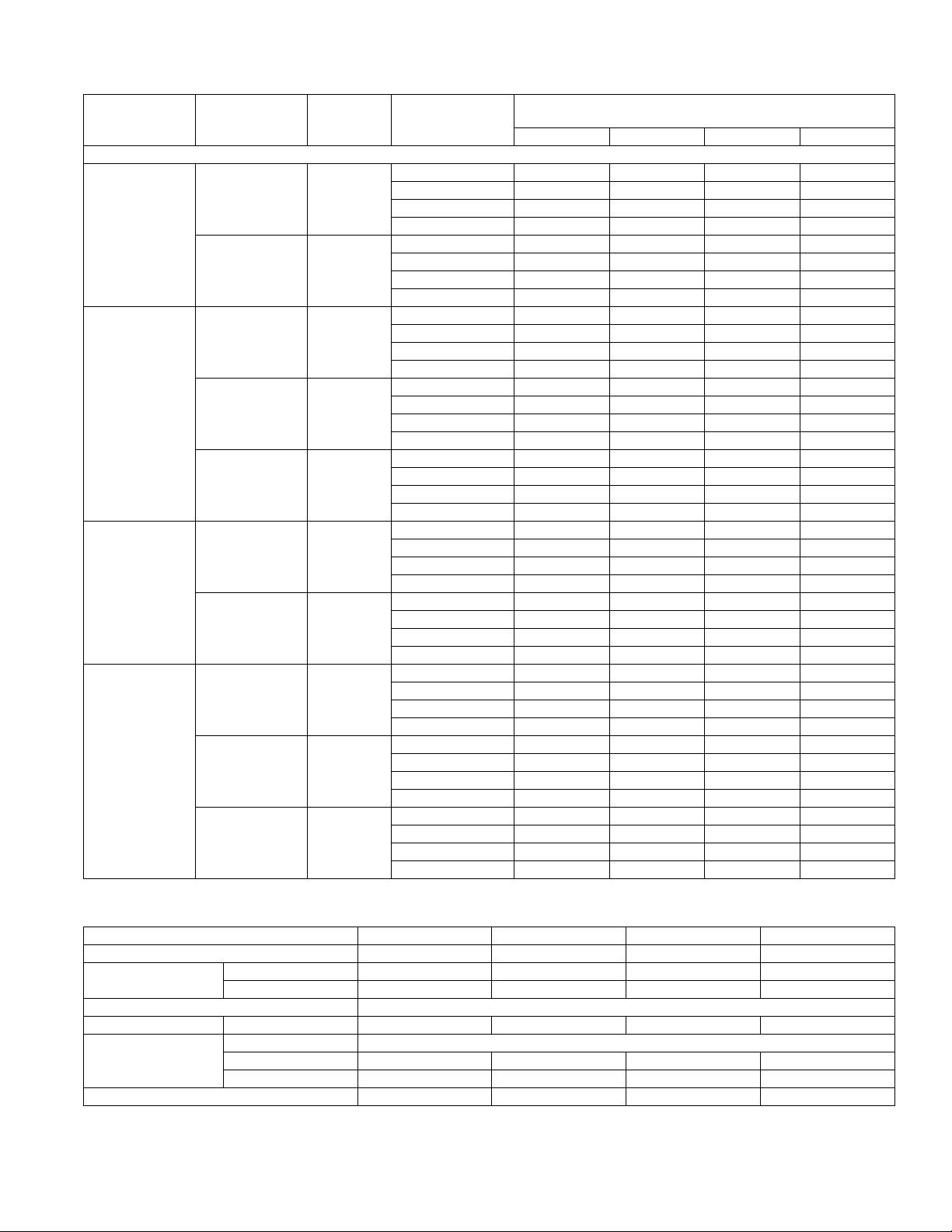
COOLING CAPACITY - Coil Only
Blower
Model
MV12B
MV12D
MV16C
MV20D
Coil
Model
MC30B**C 1025
MC36B**C 1250
MC48D**C 1125
MC60D**C 1275
MC62D**C 1450
MC42C**C 1400
MC48C**C 1650
MC48D**C 1725
MC60D**C 2000
MC62D**C 2200
Rated
CFM
Multi-Position - Upflow/Downflow/Horizontal
Entering Air F
(Dry/Wet Bulb)
85/72 41.5 37.8 33.7 29.5
80/67 36.2 32.4 28.6 24.5
75/62 29.1 25.3 24.0 19.2
70/57 24.1 21.5 18.7 15.8
85/72 52.0 47.3 42.3 37.3
80/67 41.7 36.8 32.3 27.4
75/62 32.5 27.3 29.8 22.2
70/57 27.9 25.8 23.8 22.2
85/72 46.8 42.4 37.6 33.0
80/67 37.4 33.3 29.4 24.3
75/62 28.9 24.6 21.7 19.6
70/57 25.1 23.3 21.7 19.6
85/72 53.7 48.4 43.5 37.5
80/67 43.0 38.0 33.3 27.7
75/62 33.1 28.1 24.5 22.4
70/57 28.8 26.5 24.5 22.4
85/72 91.7 78.4 68.1 52.3
80/67 73.4 61.5 52.0 38.6
75/62 57.3 45.6 38.4 31.2
70/57 49.2 43.0 38.4 31.2
85/72 88.4 76.0 63.3 50.0
80/67 70.8 59.4 48.4 37.0
75/62 55.2 43.9 35.8 29.9
70/57 47.4 41.5 35.8 29.9
85/72 100.5 86.4 72.0 56.8
80/67 80.4 67.5 55.0 42.1
75/62 62.7 49.9 40.7 34.0
70/57 53.9 47.2 40.7 34.0
85/72 119.9 101.0 80.0 62.2
80/67 96.0 79.2 62.6 45.8
75/62 74.0 58.6 46.2 37.0
70/57 64.3 55.4 46.2 37
85/72 124.8 105.2 85.3 64.7
80/67 99.9 82.5 65.2 47.7
75/62 77 61.1 48.1 38.6
70/57 66.9 57.7 48.1 38.6
85/72 131.0 110.5 89.6 67.9
80/67 104.9 86.6 68.5 50.1
75/62 81.8 64.2 50.5 40.5
70/57 70.2 60.6 50.5 40.5
35/61.5 40/68.5 45/76.0 50/84.0
550569-YTG-D-1212
MBH @ Evaporator Temperature and
Corresponding Pressure °F/PSIG
PHYSICAL & ELECTRICAL DATA
Model MV12B MV12D MV16C MV20D
Blower - Diameter x Width 10 x 7 10 x 10 10 x 10 10 x 10
Motor
Voltage 208/230
Amps Full Load (230) 4.3 4.3 5.0 7.0
Permanent Filter
Shipping/Operating Weight (lbs.) 75/71 88/82 88/82 94/88
1. Field Supplied.
1
HP 1/2 1/2 3/4 1
Nominal RPM 1200 1200 1200 1200
Type DISPOSABLE OR PERMANENT
Size 16 x 20 x 1 24 x 20 x 1 20 x 20 x 1 24 x 20 x 1
Filter Bulk Kit 1PF0601BK 1PF0604BK 1PF0602BK 1PF0604BK
Johnson Controls Unitary Products 3
Page 4
550569-YTG-D-1212
FULL CASED “A” TYPE MULTI-POSITION
Model Application
MC18B3XC1
MC24B3XC1
MC30B3XC1
MC35B3XC1
MC35C3XC1
MC36B3XC1
MC36C3XC1
MC42B3XC1
MC42C3XC1
MC43B3XC1
MC43C3XC1
MC48C3XC1
MC48D3XC1
MC60D3XC1
MC62D3XC1
Note: MC coils available with a factory installed horizontal drain pan option.
Cooling/
Heat Pump
Cooling/
Heat Pump
Cooling/
Heat Pump
Cooling/
Heat Pump
Cooling/
Heat Pump
Cooling/
Heat Pump
Cooling/
Heat Pump
Cooling/
Heat Pump
Cooling/
Heat Pump
Cooling/
Heat Pump
Cooling/
Heat Pump
Cooling/
Heat Pump
Cooling/
Heat Pump
Cooling/
Heat Pump
Cooling/
Heat Pump
Refrig.
Conn.
Types
Sweat 3.40 2 14 (2) 14 x 17.5 1 x 0.866 3/8 Enhanced None 53
Sweat 4.38 2 14 (2) 18 x 17.5 1 x 0.866 3/8 Enhanced None 56
Sweat 4.38 2 14 (2) 18 x 17.5 1 x 0.866 3/8 Enhanced None 56
Sweat 3.9 3 12 (2) 16 x 17.5 1 x 0.866 3/8 Enhanced None 65
Sweat 3.9 3 12 (2) 16 x 17.5 1 x 0.866 3/8 Enhanced None 67
Sweat 4.86 2 14 (2) 20 x 17.5 1 x 0.866 3/8 Enhanced None 65
Sweat 4.86 2 14 (2) 20 x 17.5 1 x 0.866 3/8 Enhanced None 65
Sweat 5.83 2 14 (2) 24 x 17.5 1 x 0.866 3/8 Enhanced None 72
Sweat 5.83 2 14 (2) 24 x 17.5 1 x 0.866 3/8 Enhanced None 72
Sweat 4.86 3 12 (2) 20 x 17.5 1 x 0.866 3/8 Enhanced None 73
Sweat 4.86 3 12 (2) 20 x 17.5 1 x 0.866 3/8 Enhanced None 75
Sweat 5.35 3 12 (2) 22 x 17.5 1 x 0.866 3/8 Enhanced None 82
Sweat 5.35 3 12 (2) 22 x 17.5 1 x 0.866 3/8 Enhanced None 82
Sweat 5.83 3 12 (2) 24 x 17.5 1 x 0.866 3/8 Enhanced None 86
Sweat 6.80 3 12 (2) 28 x 17.5 1 x 0.866 3/8 Enhanced None 98
Face
Area
(Sq. Ft.)
Rows
Deep
Fin Per
In.
Coil Size
Tube
Geometry
Tube Dia. Fin Type TXV
Operating
Weight
(Lbs.)
4 Johnson Controls Unitary Products
Page 5

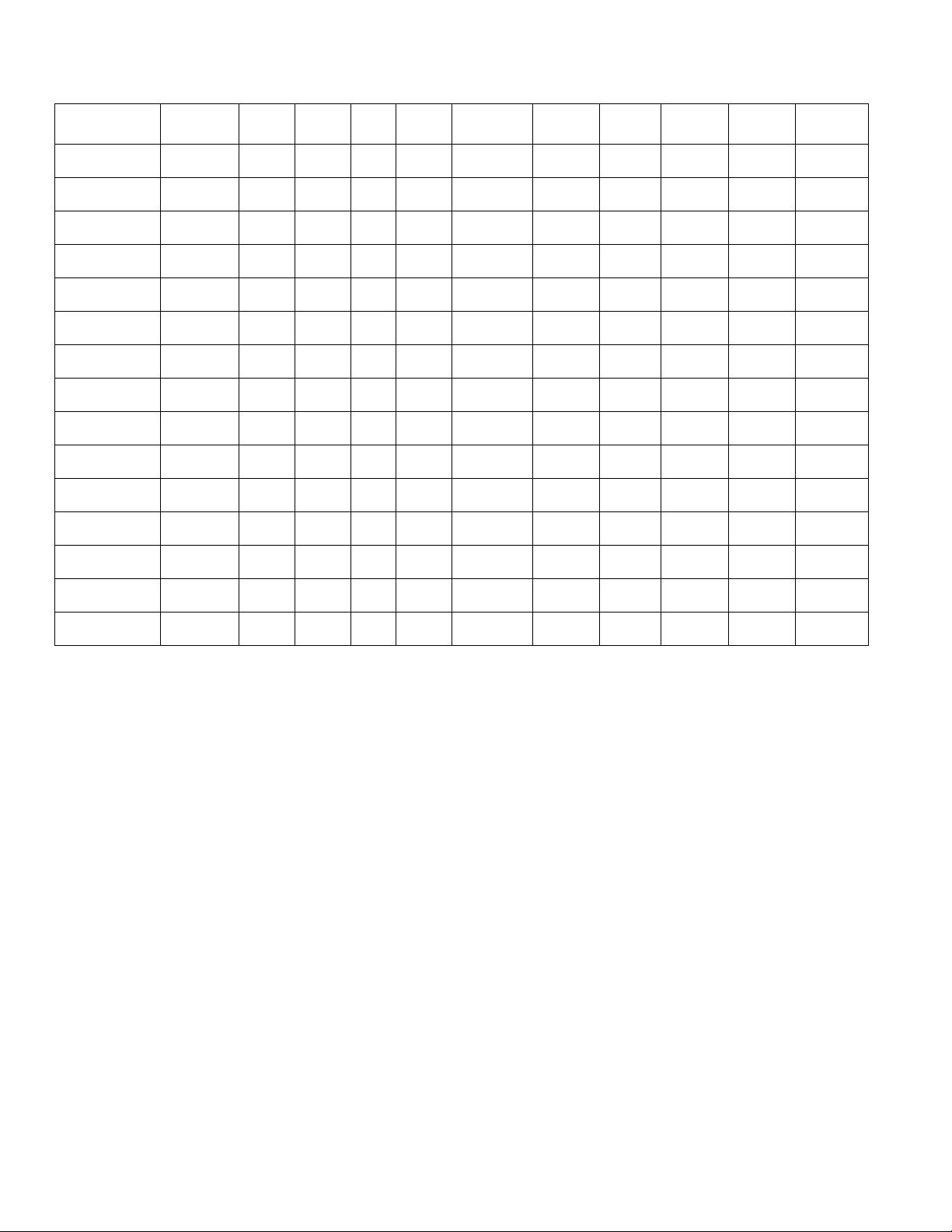
ELECTRICAL DATA - 208/230-1-60
Model Heater Model*
4HK*6500506 0.5 Heat-C 3.6 4.8 12.3 16.4 3.6 4.8 3.6 4.8 3.6 4.8
4HK*6500806 0.5 Heat-C 5.6 7.5 19.2 25.6 2.8 3.75 5.6 7.5 5.6 7.5
MV12B
4HK*6501006 0.5 Heat-B 7.2 9.6 24.6 32.8 3.6 4.8 7.2 9.6 7.2 9.6
4HK16501306 0.5 Heat B 9.8 13 33.3 44.4 3.3 4.3 6.5 8.7 9.8 13.0
4HK165N1506 0.5 Heat-B 10.8 14.4 36.9 49.1 3.6 4.8 7.2 9.6 10.8 14.4
4HK*6500506 0.5 Heat-C 3.6 4.8 12.3 16.4 3.6 4.8 3.6 4.8 3.6 4.8
4HK*6500806 0.5 Heat-C 5.6 7.5 19.2 25.6 2.8 3.75 5.6 7.5 5.6 7.5
4HK*6501006 0.5 Heat-B 7.2 9.6 24.6 32.8 3.6 4.8 7.2 9.6 7.2 9.6
MV12D
4HK16501306 0.5 Heat B 9.8 13 33.3 44.4 3.3 4.3 6.5 8.7 9.8 13.0
4HK16501506 0.5 Heat-B 10.8 14.4 36.9 49.1 3.6 4.8 7.2 9.6 10.8 14.4
4HK16501806 0.5 Heat-A 13.2 17.6 45.1 60.1 3.3 4.4 6.6 8.8 13.2 17.6
4HK16502006 0.5 Heat-A 14.4 19.2 49.2 65.5 3.6 4.8 7.2 9.6 14.4 19.2
4HK*6500506 0.5 Heat-D 3.6 4.8 12.3 16.4 3.6 4.8 3.6 4.8 3.6 4.8
4HK*6500806 0.5 Heat-D 5.6 7.5 19.2 25.6 2.8 3.75 5.6 7.5 5.6 7.5
4HK*6501006 0.5 Heat-C 7.2 9.6 24.6 32.8 3.6 4.8 7.2 9.6 7.2 9.6
MV16C
4HK16501306 0.5 Heat C 9.8 13 33.3 44.4 3.3 4.3 6.5 8.7 9.8 13.0
4HK16501506 0.5 Heat-C 10.8 14.4 36.9 49.1 3.6 4.8 7.2 9.6 10.8 14.4
4HK16501806 0.5 Heat-B 13.2 17.6 45.1 60.1 3.3 4.4 6.6 8.8 13.2 17.6
4HK16502006 0.5 Heat-B 14.4 19.2 49.2 65.5 3.6 4.8 7.2 9.6 14.4 19.2
4HK*6500506 0.5 Heat-C 3.6 4.8 12.3 16.4 3.6 4.8 3.6 4.8 3.6 4.8
4HK*6500806 0.5 Heat-C 5.6 7.5 19.2 25.6 2.8 3.75 5.6 7.5 5.6 7.5
4HK*6501006 0.5 Heat-C 7.2 9.6 24.6 32.8 3.6 4.8 7.2 9.6 7.2 9.6
MV20D
4HK16501306 0.5 Heat C 9.8 13 33.3 44.4 3.3 4.3 6.5 8.7 9.8 13.0
4HK16501506 0.5 Heat-C 10.8 14.4 36.9 49.1 3.6 4.8 7.2 9.6 10.8 14.4
4HK16501806 0.5 Heat-C 13.2 17.6 45.1 60.1 3.3 4.4 6.6 8.8 13.2 17.6
4HK16502006 0.5 Heat-C 14.4 19.2 49.2 65.5 3.6 4.8 7.2 9.6 14.4 19.2
4HK16502506 0.5 Heat-C 18.0 24.0 61.5 81.9 3.6 4.8 10.8 14.4 18.0 24.0
1. See conversion table on Page 7.
* May be 0 (no breaker) or 1 (with breaker).
Max.
Static
Min.
Speed
Tap
550569-YTG-D-1212
Total Heat
kW MBH W1 Only W2 Only W1 + W2
208V 230V 208V 230V 208V 230V 208V 230V 208V 230V
1
KW Staging
ELECTRICAL DATA - 208/230-3-60
Total Heat
kW MBH W1 Only W2 Only W1 + W2
Models
Heat Kit -
Three Phase
Max.
Static
Min.
Speed
Tap
208V 230V 208V 230V 208V 230V 208V 230V 208V 230V
MV12B 4HK06501025 0.5 Heat-B 7.2 9.6 24.6 32.8 7.2 9.6 7.2 9.6 7.2 9.6
4HK06501025 0.5 Heat-B 7.2 9.6 24.6 32.8 7.2 9.6 7.2 9.6 7.2 9.6
MV12D
4HK06501525 0.5 Heat-B 10.8 14.4 36.9 49.1 10.8 14.4 10.8 14.4 10.8 14.4
4HK06501825 0.5 Heat-A 12.9 17.2 44.7 58.7 12.9 17.2 12.9 17.2 12.9 17.2
4HK06501025 0.5 Heat-C 7.2 9.6 24.6 32.8 7.2 9.6 7.2 9.6 7.2 9.6
MV16C
4HK06501525 0.5 Heat-C 10.8 14.4 36.9 49.1 10.8 14.4 10.8 14.4 10.8 14.4
4HK06501825 0.5 Heat-B 12.9 17.2 44.7 58.7 12.9 17.2 12.9 17.2 12.9 17.2
4HK06501025 0.5 Heat-C 7.2 9.6 24.6 32.8 7.2 9.6 7.2 9.6 7.2 9.6
MV20D
4HK06501525 0.5 Heat-C 10.8 14.4 36.9 49.1 10.8 14.4 10.8 14.4 10.8 14.4
4HK16502525 0.5 Heat-C 18.0 24.0 61.4 81.4 9.0 12.0 18.0 24.0 18.0 24.0
1. See conversion table on Page 7.
1
KW Staging
Johnson Controls Unitary Products 5
Page 6

550569-YTG-D-1212
ELECTRICAL DATA (FOR SINGLE SOURCE POWER SUPPLY) - COPPER WIRE 208/230-1-60
Model Heater Model
1,*
Heater Amps
240V
Ampacity Min. Circuit Max. O.C.P.
208V 230V 208V 230V 208V 230V
4HK*6500506 20.0 27.54 30.38 30 35 10 8
4HK*6500806 31.3 39.73 44.50 40 45 8 8
MV12B
4HK*6501006 40.0 49.21 55.38 50 60 8 6
4HK16501306 54.2 64.00 72.80 70 80 4 2
4HK165N1506 60.0 70.88 80.38 90 90 4 3
4HK*6500506 20.0 27.54 30.38 30 35 10 8
4HK*6500806 31.3 39.73 44.50 40 45 8 8
4HK*6501006 40.0 49.21 55.38 50 60 8 6
MV12D
4HK16501306 54.2 64.00 72.80 70 80 4 2
4HK16501506 60.0 70.88 80.38 90 90 4 3
4HK16501806 73.3 85.32 97.00 90 100 4 3
4HK16502006 80.0 92.54 105.38 100 125 3 1
4HK*6500506 20.0 29.29 31.88 30 35 10 8
4HK*6500806 31.3 41.48 46.00 45 50 8 8
4HK*6501006 40.0 50.96 56.88 60 60 6 6
MV16C
4HK16501306 54.2 66.40 75.20 70 80 4 2
4HK16501506 60.0 72.63 81.88 90 90 3 3
4HK16501806 73.3 87.07 98.50 90 100 3 2
4HK16502006 80.0 94.29 106.88 100 125 3 1
4HK*6500506 20.0 29.29 31.88 30 35 10 8
4HK*6500806 31.3 41.48 46.00 45 50 8 8
4HK*6501006 40.0 53.08 58.75 60 60 6 6
MV20D
4HK16501306 54.2 68.40 77.20 70 80 4 2
4HK16501506 60.0 74.75 83.75 90 90 3 3
4HK16501806 73.3 89.19 100.38 90 110 3 2
4HK16502006 80.0 96.42 108.75 100 125 3 1
4HK16502506 100.0 118.08 133.75 125 150 1 1/0
1. 30 kW 3 phase not approved for single source power supply.
2. OCP = Over Current Protection device, must be HACR type Circuit Breaker or Time Delay fuse.
* May be 0 (no breaker) or 1 (with breaker).
Field Wiring
2
Amps/Type Wire Size - AWG 75°C
ELECTRICAL DATA (FOR SINGLE SOURCE POWER SUPPLY) - COPPER WIRE 208/230-3-60
Heater
Amps
240V
Min. Circuit Ampacity Max. O.C.P.
208V 230V 208V 230V 208V 230V
Models
Heat Kit -
Three Phase
MV12B 4HK06501025 23.1 30.9 34.3 35 35 8 8
4HK06501025 23.1 30.9 34.3 35 35 8 8
MV12D
4HK06501525 34.7 43.4 48.8 45 50 8 8
4HK06501825 41.4 50.6 57.1 50 60 8 6
4HK06501025 23.1 32.6 35.1 35 35 8 8
MV16C
4HK06501525 34.7 45.1 49.6 45 50 8 8
4HK06501825 41.4 52.4 58.0 60 60 6 6
MV20D
1. O.C.P. = Over Current Protection device, must be HACR type Circuit Breaker or Time Delay fuse.
4HK06501025 23.1 34.8 37.6 35 40 8 8
4HK06501525 34.7 47.3 52.1 50 60 8 6
Field Wiring
1
Amps/Type 75°C Wire Size - AWG
Electrical Data - (For Multi-Source Power Supply) - Copper Wire - 208/230-3-60
Minimum Circuit Ampacity Max. O.C.P.
Models
Heater
Model
1st 2nd 3rd 1st 2nd 3rd 1st 2nd 3rd
208/230 208/230 208/230 208/230 208/230 208/230 208/230 208/230 208/230
MV20D 4HK16502525 41.0/44.9 31.3/36.1 – 45/45 35/40 – 8/8 8/8 –
1. O.C.P. = Over Current Protection device, must be HACR type Circuit Breaker or Time Delay fuse.
1
Amps/Type 75°C Wire Size - AWG
Circuit
6 Johnson Controls Unitary Products
Page 7

ELECTRICAL DATA (FOR MULTI SOURCE POWER SUPPLY) - COPPER WIRE 208/230-1-60
ELECTRIC HEAT
WITHOUT CIRCUIT BREAKER
SINGLE SOURCE (2.5 - 10 KW)
GND. LUG
POWER
SUPPLY
GND.
LUG
ELECTRIC HEAT
WITHOUT CIRCUIT BREAKER
3 PHASE (10 - 15 KW)
GND. LUG
POWER
SUPPLY
GND.
LUG
1 PHASE ELECTRIC HEAT
WITH CIRCUIT BREAKER
AS SHIPPED FROM FACTORY
SINGLE SOURCE
(2.5 - 25 KW) - 25 KW SHOWN
GND. LUG
POWER
SUPPLY
GND.
LUG
1 PHASE ELECTRIC HEAT
WITH CIRCUIT BREAKER
& BREAKER BAR REMOVED
MULTI-SOURCE (15 - 25 KW) - 25 KW SHOWN
GND. LUG
POWER
SUPPLY 1
GND.
LUG
POWER
SUPPLY 2
POWER
SUPPLY 3
TYPICAL WIRING WITHOUT ELECTRIC HEAT
GND. LUG
POWER
SUPPLY
GND.
LUG
POWER WIRING (208/230-1-60)
NOTE: USE ONLY COPPER CONDUCTORS
TERMINAL
BLOCK
TERMINAL
BLOCK
MAYBE1,2,OR3
CIRCUIT BREAKERS
MAYBE1,2,OR3
CIRCUIT BREAKERS
(JUMPER BAR)
CONNECT LEADS WITH WIRE NUTS
(TYPICAL ALL HEAT KITS)
Min. Circuit Ampacity Max. O.C.P.1 Amps/Type 75°C Wire Size - AWG
Model
Heater
Model
1st 2nd 3rd 1st 2nd 3rd 1st 2nd 3rd
Circuit Circuit Circuit
208/230 208/230 208/230 208/230 208/230 208/230 208/230 208/230 208/230
MV12B
4HK16501306 41.7/47.9 22.4/25.0 – 50/50 30/30 – 6/6 12/10 –
4HK165N1506 49.2/55.4 21.7/25.0 – 50/60 25/25 – 8/6 10/10 –
4HK16501306 41.7/47.9 22.4/25.0 – 50/50 30/30 – 6/6 12/10 –
MV12D
4HK16501506 49.2/55.4 21.7/25.0 – 50/60 25/25 – 8/6 10/10 –
4HK16501806 45.6/51.2 39.7/45.8 – 50/60 40/50 – 8/6 8/8 –
4HK16502006 49.2/55.4 43.3/50.0 – 50/60 45/50 – 8/6 8/8 –
4HK16501306 42.9/49.1 23.6/26.2 – 50/50 30/30 – 6/6 12/10 –
MV16C
4HK16501506 51.0/56.9 21.7/25.0 – 50/60 25/25 – 8/6 10/10 –
4HK16501806 17.3/52.7 39.7/45.8 – 50/60 40/50 – 8/6 8/8 –
4HK16502006 51.0/56.9 43.3/50.0 – 50/60 45/50 – 8/6 8/8 –
4HK16501306 43.9/50.1 24.6/27.2 – 50/60 30/30 – 6/6 10/10 –
4HK16501506 53.1/58.8 21.7/25.0 – 60/60 25/25 – 6/6 10/10 –
MV20D
4HK16501806 49.5/54.6 39.7/45.8 – 50/60 40/50 – 8/6 8/8 –
4HK16502006 53.1/58.8 43.3/50.0 – 60/60 45/50 – 6/6 8/8 –
4HK16502506 49.3/56.5 43.3/50.0 21.7/25.0 50/60 45/50 25/25 8/6 8/8 10/10
1. OCP = Over Current Protection device, must be HACR type Circuit Breaker or Time Delay fuse.
KW & MBH CONVERSIONS
FOR
208-VOLT
230-VOLT 240-VOLT .918
OPERATION MULTIPLY
240-VOLT
TABULATED KW & MBH BY
550569-YTG-D-1212
.751
ELECTRICAL DA TA - COOLING UNIT ONL Y (60 Hz)
MODEL
MV12B 4.7 4.3 5.9 5.4 15 14
MV12D 4.7 4.3 5.9 5.4 15 14
MV16C 6.1 5.0 7.6 6.9 15 14
MV20D 7.8 7.0 9.7 8.8 15 14
1. OCP = Over Current Protection device, must be HACR type Circuit Breaker or Time Delay fuse.
POWER WIRING
Johnson Controls Unitary Products 7
Total Motor Amps Minimum Circuit Ampacity
60 Hertz 60 Hertz
208V 230V 208V 230V
Max. O.C.P.
1
Minimum Wire Size
Amps/Type
AWG @ 75°C
Page 8

550569-YTG-D-1212
1/2”
22”
C
19-7/8”
B
D
1-1/2”
3-1/2”
A
22”
21”
1/2”
(All four sides)
2” Max
Thick
Filter
3/4”
1/2”
3-1/2”
1/2”
7/8”
NOTE: May be used with up to a 2” filter.
Required for downflow application.
May also be used in upflow application.
Comes with 1” permanent filter.
All dimensions are inches. They are subject to change
without notice. Certified dimensions will be provided upon
request.
1”
A
16-1/2”
20”
23-1/2”
ACCESSORY FOOTPRINT
ACCESSORIES
Refer to Price Manual for specific model numbers.
Electric Heaters - Models shown under Electrical Data include
sequencers and temperature limit switches and fusible links for
safe, efficient operation. Circuit breakers are provided where
shown.
Suspension Kit - Suspension Kit Model 1BH0601 is designed
specifically for upflow application of the units contained in this
technical guide. For suspension of these units in horizontal
applications, it is recommended to use angle support brackets
with threaded rods at locations shown in air handler installation
instructions.
Filter Rack - One of the following external filter rack accessories: 1FR07* or 1FR08* must be used when unit is installed for
application outlined.
Combustible Floor Base - If an electric h eat accessory which
is rated for greater than zero clearance to combustible surfaces
is installed in these air handlers in the downflow operating positions on a combustible floor, one of the following combustible
floor base accessories is required: 1FB1817, 1FB1821, or
1FB1824.
FILTER RACK ACCESSORY
DIMENSIONS
Filter Rack Model
Multi-PositionHorizontal Only ABCDWidthLengthThickness
Used With
1FR0817 1FR0717 MV12B 17-1/2 16-3/8 15-1/2 21 16 20 1
1FR0821 1FR0721 MV16C 21 19-7/8 19 21 20 20 1
1FR0824 1FR0724 MV12D, MV20D 24-1/2 23-3/8 22-1/2 21 24 20 1
8 Johnson Controls Unitary Products
Rack Dimensions Inches Filter Dimensions Inches
Page 9

550569-YTG-D-1212
DOWNFLOW
AIR HANDLER
WARM AIR PLENUM
WITH 1” FLANGES
FIBERGLASS
INSULATION
FIBERGLASS TAPE
UNDER FLANGE
COMBUSTIBLE FLOOR
BASE ACCESSORY
A
B
B
A
AIR HANDLER
DEPTH
FRONT
FLOOR
1
10-47/64
PLENUM
12-1/2
FLOOR OPENING
APPROX. 1/2”
CLEARANCE
ALL AROUND
FLOOR
A
AIR HANDLER
WIDTH
COMBUSTIBLE
FLOOR BASE
11
APPROX. 1/2”
CLEARANCE
ALL AROUND
C
FLOOR OPENING
B
PLENUM
All dimensions are in inches. They are subject to change without notice.
Certified dimensions will be provided upon request.
UPFLOW
DOWNFLOW
HORIZONTAL RIGHT
HORIZONTAL LEFT
COMBUSTIBLE FLOOR BASE ACCESSORY
DIMENSIONS
Floor Base Model Used with
ABCD
1FB1817 MV12B 19.9 18.0 14.9 16.9
1FB1821 MV16C 23.4 21.5 18.4 20.4
1FB1824 MV12D, MV20D 26.9 25.0 21.9 23.9
Dimensions
APPLICATION FACTORS - Rated CFM vs. Actual CFM
% OF RATED AIR FLOW 80% 9 0% RATED CFM 110% 120%
CAPACITY FACTOR 0.96 0.98 1.00 1.02 1.03
TYPICAL APPLICATIONS WITH MC MULTI-POSITION COILS
Johnson Controls Unitary Products 9
Page 10

550569-YTG-D-1212
Air Handler Control Wiring
Typical A/C - Cooling only Applications
THERMOSTAT
AIR HANDLER
BOARD
1-STAGE
AIR CONDITIONING
RR
G
Y
W1
W2
C
G
W1
W2
Y
C
Y/Y2
Y1
O
HUM
X/L
COM
HUMIDISTAT
*
THERMOSTAT
AIR HANDLER
BOARD
1-STAGE
AIR CONDITIONING
RR
G
Y
W1
W2
C
G
W1
W2
Y
C
Y/Y2
Y1
O
HUM
X/L
COM
HUMIDISTAT
*
Air Handler Control Wiring
Typical A/C with Electric Heat Applications
y
Two Stage H/P with York Guard VI Board & Copeland “Ultra Tech”
Conventional Application - Not Hot Heat Pump
THERMOSTAT
AIR HANDLER
BOARD
2 - STAGE SCROLL
HEAT PUMP
RR R
GG
Y2
E
W
W
O O
O
X/L X/L X/L
C
C
Y/Y2
Y1
Y1
Y2 OUT
Y2
W2 OUT
W1 OUT
BS
W2
W1
HUM
COM
HUMIDISTAT
*
Y1
7RXFK6FUHHQ
&RPPXQLFDWLQJ&RQWURO
$
5
%
&
$LU+DQGOHU
&RPPXQLFDWLQJ&RQWURO
&
%
5
:
:
$
2
+80
;/
5
*
<<
<
&20
$LU&RQGLWLRQHU+HDW3XPS
&RPPXQLFDWLQJ&RQWURO
&
%
5
$
CONVENTIONAL CONTROL WIRING (24 VAC)
* Optional dehumidification humidistat switch contacts open on humidity rise.
CONTROL WIRING USING COMMUNICATION
10 Johnson Controls Unitary Products
Page 11

AIR HANDLER AIR FLOW DATA
12B 12D
High Low High Low COOL Tap ADJ Tap
1385 896 1411 907 A B
1137 745 1159 767 B B
1203 777 1227 799 A A
1019 650 1007 662 B A
1085 690 1083 716 A C
943 615 958 629 C B
889 585 908 603 B C
746 493 767 537 D B
817 537 840 568 C A
646 467 660 516 D A
738 481 780 532 C C
580 465 603 517 D C
16C 20D JUMPER SETTINGS
High Low High Low COOL Tap ADJ Tap
2005 1433 2404 1579 A B
1768 1145 2022 1313 B B
2009 1299 2167 1388 A A
1615 1040 1801 1159 B A
1787 1159 1924 1256 A C
1524 988 1818 1175 C B
1445 940 1620 1024 B C
1350 883 1638 1049 D B
1384 906 1628 1030 C A
1215 800 1442 929 D A
1236 810 1434 911 C C
1086 716 1305 859 D C
HIGH/LOW SPEED COOLING AND HEAT PUMP AIRFLOW
CFM
550569-YTG-D-1212
JUMPER SETTINGS
HIGH/LOW SPEED ELECTRIC HEAT AIRFLOW
CFM
12B 12D
High Low High Low HEAT Tap ADJ Tap
1385 900 1411 913 A N/A
1228 795 1258 817 B N/A
1137 748 1159 769 C N/A
917 603 928 619 D N/A
16C 20D JUMPER SETTINGS
High Low High Low HEAT Tap ADJ Tap
2006 1411 2408 1515 A N/A
1868 1243 2218 1285 B N/A
1468 983 1902 1070 C N/A
1248 840 1407 823 D N/A
1. Airflow at nominal voltage, bottom return at 0.5 external sta tic pressure, tested without filter installed, dry coil conditions.
2. These units have variable speed motors that automatically adjust to provide constant CFM from 0.0” to 0.6” w.c. static pressure.
3. From 0.6” to 1.0” static pressure, CFM is reduced by 2% per 0.1” increase in static.
4. Operation on duct systems with greater than 1.0” w.c. external static pressure is not recommended.
5. Both the COOL and the ADJUST tap must be set to obtain the cooling airflow desired (CFM).
6. The ADJ tap does not affect the HEAT tap setting.
7. Low speed cooling used only with two stage outdoor units. (Speed is preset to 65% of high speed).
8. Dehumidification speed is 85% of jumper selected COOL tap and ADJUST tap.
9. When operating in both heat pump and electric heat modes, the airflow (CFM) will be per HEAT Tap CFM values only.
10. At some settings, LOW COOL and/or LOW HEAT airflow may be lower than what is required to operate an airflow switch on certain models of electronic air
cleaners. Consult the instructions for the electronic air cleaner for further details.
11. Airflow (CFM) indicator light (LED2) flashes once for every 100 CFM (i.e.: 12 Flashes is 1200 CFM) – blinks are approximate +/- 10% of actual CFM.
JUMPER SETTINGS
Johnson Controls Unitary Products 11
Page 12

NOTES
Subject to change without notice. Published in U.S.A. 550569-YTG-D-1212
Copyright © 2012 by Johnson Controls, Inc. All rights reserved. Supersedes: 550569-YTG-C-1010
York International Corp.
5005 York Drive
Norman, OK 73069
 Loading...