

Page 1
255427-YTG-F-1006
DESCRIPTION
This unique modular system allows the flexibility to handle any
application. These versatile coils and blowers may be used for
upflow, downflow, or horizontal left or right applications. They
may be combined to function as a cooling only unit or with a heat
pump including electric heat for 1 and 3 phase applications. The
blower and electric heater could be used as stand alone electric
furnaces.
TECHNICAL GUIDE
MODELS: MV
MODULAR VARIABLE SPEED AIR HANDLERS
FOR USE WITH SPLIT SYSTEM
COOLING & HEAT PUMP
1200 - 2000 CFM BLOWERS
3 - 5 TON COILS
OPTIONAL 1 & 3
φ ELECTRIC HEATERS
ISO 9001
Certified Quality
Management System
FEATURES
BLOWERS - Models to match any air flow or voltage require-
ment. The compact size allows easy installation. Blowers are
sized to deliver design air quantity both efficiently and quietly.
The motors provide a selection of air quantities to match any
application. All models include a one-minute blower off delay as
standard to enhance system efficiency ratings. The durable, prepainted steel protects the unit against rust and corrosion. All
models have 1 inch foil face fiber glass insulation, provid ing a
thermal insulation value of R-4.2.
COILS - Staggered rows of rifled copper tubes are mechanically
expanded into enhanced surface aluminum fins to provide high
heat transfer and long-lasting quality. The MC multi-position
coils may be used for upflow, downflow, and horizontal left or
right applications. Coil cabinets are insulated with 3/4" foil face
insulation to prevent sweating.
ELECTRIC HEATERS - Both single and three phase electric
heater models are available to match any requirement. All heaters include nickel-chromium elements with a 5-year limited warranty on 1 Ø heating elements and 1 year limited warranty on 3
Ø heating elements. Sequential operation is provided to control
heaters in all models. Circuit breakers are used in 208/230 volt,
single-phase heaters of 15 KW and larger.
Models equipped with circuit breakers may be altered in the field
to use multi-source power supply. Over-temperature limit
switches provide protection from airflow loss with fusible link
backup protection.
ACCESSORIES - A full line of matching accessories available
for use with the blower and coils to allow any type application.
LIMIT ATIONS - These units must be wired and installed in
accordance with all national and local safety codes.
Voltage limits are as follows:
AIR HANDLER VOLTAGE
208/230-1-60 187 - 253
* Rated in accordance with ARI Standard 110, utilization range “A”.
Air flow must be within the minimum and maximum limits approved for electric
heat, evaporator coils and outdoor units.
NORMAL OPERATING
VOLTAGE RANGE*
Due to continuous product improve m en t, specifications
subject to change without notice.
Visit us on the web at www.york.com
Additional rating information can be found at
www.ari.org/aridirectory
FOR DISTRIBUTION USE ONLY - NOT TO BE USED AT POINT OF RETAIL SALE
Page 2
255427-YTG-F-1006
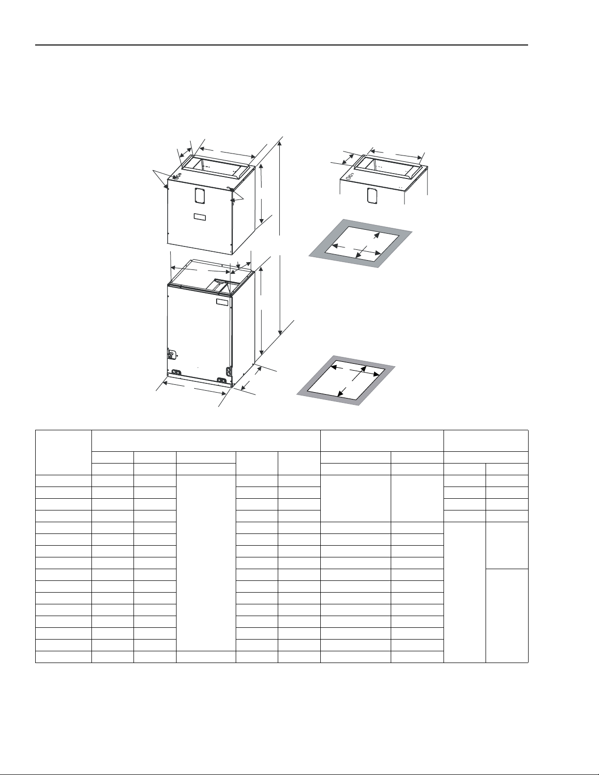
DIMENSIONS - (BLOWER WITH MC COILS)
NOTE: Power wiring may be brought into the unit through one of the knockouts in either the top or the left side panel. Multiple
knockouts are provided to accommodate all of the electric heat and transformer accessories that are available. Use the knockouts that provide the best wire routing for the accessory being used.
AIR HANDLER TOP (All Models)
10-3/8”
D
D
20-1/4”
E
20-1/2”
COIL BOTTOM OPENING
J
AIR HANDLER
MA / MV
COIL
MC
10-3/8”
E
A
K
C
(TOTAL HEIGHT)
20-3/8”
E
A
21.5”
B
AIR HANDLER BOTTOM OPENING
DIMENSIONS
Dimensions
Model
MV12B 25 17-1/2
AB C
Height Width Total Height Power Control Liquid Vapor
DE
16-1/2 14-19/32
MV12D 25 24-1/2 23-1/2 21-19/32 – –
MV16C 25 21 20 18-3/32 – –
Wiring K.O.’s
JKLine Size
7/8" (1/2")
1-3/8" (1")
1-23/32" (1-1/4")
1
7/8" (1/2")
MV20D 25 24-1/2 23-1/2 21-19/32 – –
MC24B**H 26-1/2 17-1/2 16-1/2 16-3/8 – –
MC30B**H 26-1/2 17-1/2 16-1/2 16-3/8 – –
MC35B**H 22 17-1/2 16-1/2 16-3/8 – –
MC35C**H 26-1/2 21 20 19-7/8 – –
MC36B**H 26-1/2 17-1/2 16-1/2 16-3/8 – –
47 to 57
Depending
on combination.
MC36C**H 26/1/2 21 20 19-7/8 – –
MC42B**H 32 17-1/2 16-1/2 16-3/8 – –
MC42C**H 32 21 20 19-7/8 – –
MC48C**H 32 21 20 19-7/8 – –
MC48D**H 32 24-1/2 23-1/2 23-3/8 – –
MC60D**H 32 24-1/2 23-1/2 23-3/8 – –
MC61D**H 36 24-1/2 61 23-1/2 23-3/8 – –
1. Parenthesis indicate conduit size
Refrigerant
Connections
––
3/8
3/4
7/8
2 Unitary Products Group
Page 3
255427-YTG-F-1006
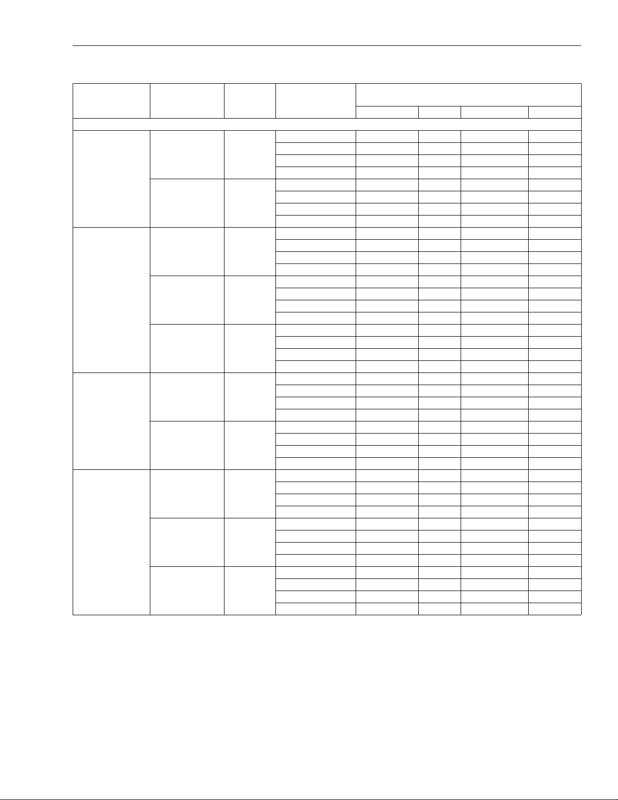
COOLING CAPACITY - COIL ONLY
Blower
Model
MV12B
MV12D
MV16C
MV20D
Coil
Model
MC30B**H 1025
MC36B**H 1250
MC48D**H 1125
MC60D**H 1275
MC61D**H 1450
MC42C**H 1400
MC48C**H 1650
MC48D**H 1725
MC60D**H 2000
MC61D**H 2200
Rated
CFM
Multi-Position - Upflow / Downflow / Horizontal
Entering Air °F
(Dry / Wet Bulb)
85 / 72 41.5 37.8 33.7 29.5
80 / 67 36.2 32.4 28.6 24.5
75 / 62 29.1 25.3 24.0 19.2
70 / 57 24.1 21.5 18.7 15.8
85 / 72 52.0 47.3 42.3 37.3
80 / 67 41.7 36.8 32.3 27.4
75 / 62 32.5 27.3 29.8 22.2
70 / 57 27.9 25.8 23.8 22.2
85 / 72 46.8 42.4 37.6 33.0
80 / 67 37.4 33.3 29.4 24.3
75 / 62 28.9 24.6 21.7 19.6
70 / 57 25.1 23.3 21.7 19.6
85 / 72 53.7 48.4 43.5 37.5
80 / 67 43.0 38.0 33.3 27.7
75 / 62 33.1 28.1 24.5 22.4
70 / 57 28.8 26.5 24.5 22.4
85 / 72 91.7 78.4 68.1 52.3
80 / 67 73.4 61.5 52.0 38.6
75 / 62 57.3 45.6 38.4 31.2
70 / 57 49.2 43.0 38.4 31.2
85 / 72 88.4 76.0 63.3 50.0
80 / 67 70.8 59.4 48.4 37.0
75 / 62 55.2 43.9 35.8 29.9
70 / 57 47.4 41.5 35.8 29.9
85 / 72 100.5 86.4 72.0 56.8
80 / 67 80.4 67.5 55.0 42.1
75 / 62 62.7 49.9 40.7 34.0
70 / 57 53.9 47.2 40.7 34.0
85 / 72 119.9 101.0 80.0 62.2
80 / 67 96.0 79.2 62.6 45.8
75 / 62 74.0 58.6 46.2 37.0
70 / 57 64.3 55.4 46.2 37
85 / 72 124.8 105.2 85.3 64.7
80 / 67 99.9 82.5 65.2 47.7
75 / 62 77 61.1 48.1 38.6
70 / 57 66.9 57.7 48.1 38.6
85 / 72 131.0 110.5 89.6 67.9
80 / 67 104.9 86.6 68.5 50.1
75 / 62 81.8 64.2 50.5 40.5
70 / 57 70.2 60.6 50.5 40.5
MBH @ Evaporator Temperature and
Corresponding Pressure °F / PSIG
35 / 61.5 40 / 68.5 45 / 76.0 50 / 84.0
Unitary Products Group 3
Page 4
255427-YTG-F-1006
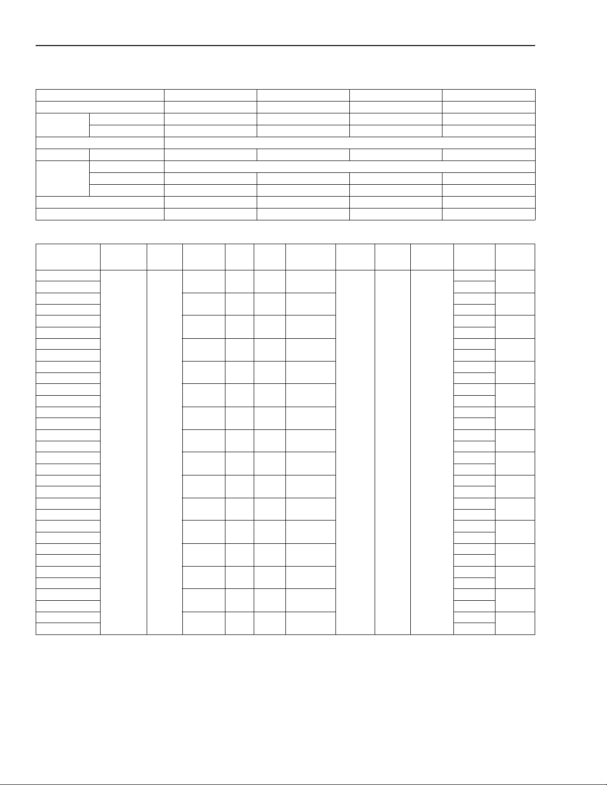
PHYSICAL & ELECTRICAL DATA
Model MV12B MV12D MV16C MV20D
Blower - Diameter x Width 10 x 7 10 x 10 10 x 10 10 x 10
Motor
HP 1/2 1/2 3/4 1
Nominal RPM 1200 1200 1200 1200
Voltage 208/230
Amps Full Load (230) 4.3 4.3 5.0 7.0
Type DISPOSABLE OR PERMANENT
Filter
Size
Permanent Type Kit
16 x 20 x 1 22 x 20 x 1 20 x 20 x 1 22 x 20 x 1
1PF0601BK 1PF0603BK 1PF0602BK 1PF0603BK
Filter Rack 1FR0717 1FR0724 1FR0721 1FR0724
Shipping / Operating Weight (lbs.) 68 / 62 88 / 82 75 / 69 93 / 87
COILS
Model Application
MC18A3XH1
MC18A2AH1 2A
MC18B3XH1
MC18B2AH1 2A
MC24A3XH1
MC24A2AH1 2A
MC24B3XH1
MC24B2AH1 2A
MC30A3XH1
MC30A2AH1 2A
MC30B3XH1
MC30B2AH1 2A
MC35B3XH1
MC35C3XH1 None
MC36A3XH1
MC36A2AH1 2A
MC36B3XH1
MC36B2AH1 2A
MC36C3XH1
MC36C2AH1 2A
MC42B3XH1
MC42B2CH1 2C
MC42C3XH1
MC42C2CH1 2C
MC48C3XH1
MC48C2CH1 2C
MC48D3XH1
MC48D2CH1 2C
MC60D3XH1
MC60D2CH1 2C
MC61D3XH1
MC61D2CH1 2C
Cooling /
Heat Pump
Refrig.
Conn.
Types
Sweat
Face
Area
(Sq. Ft.)
3.40 2 14 (2) 14 x 17.5
3.40 2 14 (2) 14 x 17.5
4.38 2 14 (2) 18 x 17.5
4.38 2 14 (2) 18 x 17.5
4.38 2 14 (2) 18 x 17.5
4.38 2 14 (2) 18 x 17.5
3.90 3 12 (2) 16 x 17.5
4.86 2 14 (2) 20 x 17.5
4.86 2 14 (2) 20 x 17.5
4.86 2 14 (2) 20 x 17.5
5.83 2 14 (2) 24 x 17.5
5.83 2 14 (2) 24 x 17.5
5.35 3 12 (2) 22 x 17.5
5.35 3 12 (2) 22 x 17.5
5.83 3 12 (2) 24 x 17.5
6.80 3 12 (2) 28 x 17.5
Rows
Deep
Fin
Per
In.
Coil Size
Tube
Geometry
1 x 0.866 3/8 Enhanced
Tube
Dia.
Fin
Type
TXV
None
None
None
None
None
None
None
None
None
None
None
None
None
None
None
None
Operating
Weight
(Lbs.)
53
53
56
56
56
56
65
64
65
65
72
72
82
82
86
98
4 Unitary Products Group
Page 5

255427-YTG-F-1006
ELECTRICAL DATA - 208/230-1-60
Model Heater Model*
4HK*6500506 0.5 Heat-D 3.6 4.8 12.3 16.4 3.6 4.8 3.6 4.8 3.6 4.8
MV12B
MV12D
MV16C
MV20D
1. See conversion table on Page 7.
* May be 0 (no breaker) or 1 (with breaker).
4HK*6500806 0.5 Heat-D 5.6 7.5 19.2 25.6 2.8 3.75 5.6 7.5 5.6 7.5
4HK*6501006 0.5 Heat-D 7.2 9.6 24.6 32.8 3.6 4.8 7.2 9.6 7.2 9.6
4HK165N1506 0.5 Heat-D 10.8 14.4 36.9 49.1 3.6 4.8 7.2 9.6 10.8 14.4
4HK*6500506 0.5 Heat-D 3.6 4.8 12.3 16.4 3.6 4.8 3.6 4.8 3.6 4.8
4HK*6500806 0.5 Heat-D 5.6 7.5 19.2 25.6 2.8 3.75 5.6 7.5 5.6 7.5
4HK*6501006 0.5 Heat-D 7.2 9.6 24.6 32.8 3.6 4.8 7.2 9.6 7.2 9.6
4HK16501506 0.5 Heat-D 10.8 14.4 36.9 49.1 3.6 4.8 7.2 9.6 10.8 14.4
4HK16501806 0.5 Heat-D 13.2 17.6 45.1 60.1 3.3 4.4 6.6 8.8 13.2 17.6
4HK16502006 0.5 Heat-D 14.4 19.2 49.2 65.5 3.6 4.8 7.2 9.6 14.4 19.2
4HK*6501006 0.5 Heat-D 7.2 9.6 24.6 32.8 3.6 4.8 7.2 9.6 7.2 9.6
4HK16501506 0.5 Heat-D 10.8 14.4 36.9 49.1 3.6 4.8 7.2 9.6 10.8 14.4
4HK16501806 0.5 Heat-D 13.2 17.6 45.1 60.1 3.3 4.4 6.6 8.8 13.2 17.6
4HK16502006 0.5 Heat-D 14.4 19.2 49.2 65.5 3.6 4.8 7.2 9.6 14.4 19.2
4HK16502506 0.5 Heat-D 18.0 24.0 61.5 81.9 3.6 4.8 10.8 14.4 18.0 24
Max.
Static
Min.
Speed
Tap
Total Heat
KW MBH W1 Only W2 Only W1 + W2
208V 240V 208V 240V 208V 240V 208V 240V 208V 240V
1
KW Staging
ELECTRICAL DATA - 208/230-3-60
Models
MV12BN21 4HK06501025 0.5 Heat-D 7.2 9.6 24.6 32.8 7.2 9.6 7.2 9.6 7.2 9.6
MV12DN21
MV16CN21
MV20DN21
1. See conversion table on Page 7.
Heat Kit -
Three Phase
4HK06501025 0.5 Heat-D 7.2 9.6 24.6 32.8 7.2 9.6 7.2 9.6 7.2 9.6
4HK06501525 0.5 Heat-D 10.8 14.4 36.9 49.1 10.8 14 .4 10.8 14.4 10.8 14.4
4HK06501825 0.5 Heat-D 12.9 17.2 44.7 58.7 12.9 17 .2 12.9 17.2 12.9 17.2
4HK06501025 0.5 Heat-D 7.2 9.6 24.6 32.8 7.2 9.6 7.2 9.6 7.2 9.6
4HK06501525 0.5 Heat-D 10.8 14.4 36.9 49.1 10.8 14 .4 10.8 14.4 10.8 14.4
4HK06501825 0.5 Heat-D 12.9 17.2 44.7 58.7 12.9 17 .2 12.9 17.2 12.9 17.2
4HK06501025 0.5 Heat-D 7.2 9.6 24.6 32.8 7.2 9.6 7.2 9.6 7.2 9.6
4HK06501525 0.5 Heat-D 10.8 14.4 36.9 49.1 10.8 14 .4 10.8 14.4 10.8 14.4
4HK16502525 0.5 Heat-D 18.0 24.0 61.4 81.4 9.0 12.0 18.0 24.0 18.0 24.0
Max.
Static
Min.
Speed
Tap
208V 240V 208V 240V 208V 240V 208V 240V 208V 240V
Total Heat
KW MBH W1 Only W2 Only W1 + W2
1
KW Staging
Unitary Products Group 5
Page 6

ELECTRICAL DATA (FOR SINGLE SOURCE POWER SUPPLY) - COPPER WIRE 208/230-1-60
Field Wiring
1,*
Model
Heater Model
Heater Amps Ampacity Min. Circuit
Max. O.C.P.
240V 208V 240V 208V 240V 208V 240V
4HK*6500506 20.0 27.54 30.38 30 35 10 8
MV12B
4HK*6500806 31.3 39.73 44.50 40 45 8 8
4HK*6501006 40.0 49.21 55.38 50 60 8 6
4HK165N1506 60.0 70.88 80.38 90 90 4 3
4HK*6500506 20.0 27.54 30.38 30 35 10 8
4HK*6500806 31.3 39.73 44.50 40 45 8 8
MV12D
4HK*6501006 40.0 49.21 55.38 50 60 8 6
4HK16501506 60.0 70.88 80.38 90 90 4 3
4HK16501806 73.3 85.32 97.00 90 100 4 3
4HK16502006 80.0 92.54 105.38 100 125 3 1
4HK*6500506 20.0 29.29 31.88 30 35 10 8
4HK*6500806 31.3 41.48 46.00 45 50 8 8
MV16C
4HK*6501006 40.0 50.96 56.88 60 60 6 6
4HK16501506 60.0 72.63 81.88 90 90 3 3
4HK16501806 73.3 87.07 98.50 90 100 3 2
4HK16502006 80.0 94.29 106.88 100 125 3 1
4HK*6501006 40.0 53.08 58.75 60 60 6 6
4HK16501506 60.0 74.75 83.75 90 90 3 3
MV20D
4HK16501806 73.3 89.19 100.38 90 110 3 2
4HK16502006 80.0 96.42 108.75 100 125 3 1
4HK16502506 100.0 118.08 133.75 125 150 1 1/0
1. 30 KW 3 phase not approved for single source power supply.
2. OCP = Over Current Protection device, must be HACR type Circuit Breaker or Time Delay fuse.
* May be 0 (no breaker) or 1 (with breaker).
2
Amps/Type
255427-YTG-F-1006
Wire Size - AWG 75°C
ELECTRICAL DATA (FOR SINGLE SOURCE POWER SUPPLY) - COPPER WIRE 208/230-3-60
Models
Heat Kit -
Three Phase
Heater
Amps
240V
Min. Circuit Ampacity
208V 240V 208V 240V 208V 240V
12B 4HK06501025 23.1 30.9 34.3 35 35 8 8
4HK06501025 23.1 30.9 34.3 35 35 8 8
12D
4HK06501525 34.7 43.4 48.8 45 50 8 8
4HK06501825 41.4 50.6 57.1 50 60 8 6
4HK06501025 23.1 32.6 35.1 35 35 8 8
16C
4HK06501525 34.7 45.1 49.6 45 50 8 8
4HK06501825 41.4 52.4 58.0 60 60 6 6
20D
4HK06501025 23.1 34.8 37.6 35 40 8 8
4HK06501525 34.7 47.3 52.1 50 60 8 6
1. O.C.P. = Over Current Protection device, must be HACR type Circuit Breaker or Time Delay fuse.
TA BLE 1: Electrical Data - (For
Models
Heater
Model
Multi-Source
Minimum Circuit Ampacity
1st 2nd 3rd 1st 2nd 3rd 1st 2nd 3rd
Power Supply) - Copper Wire - 208/230-3-60
Max. O.C.P.
Circuit
208/240 208/240 208/240 208/240 208/240 208/240 208/240 208/240 208/240
20D 4HK16502525 41.0 / 44.9 31.3 / 36.1 - / - 45 / 45 35 / 40 - / - 8 / 8 8 / 8 - / -
1. O.C.P. = Over Current Protection device, must be HACR type Circuit Breaker or Time Delay fuse.
Field Wiring
Max. O.C.P.
1
Amps/Type
1
Amps/Type
75°C Wire Size - AWG
75°C Wire Size - AWG
6 Unitary Products Group
Page 7

255427-YTG-F-1006
ELECTRICAL DATA (FOR MULTI SOURCE POWER SUPPLY) - COPPER WIRE 208/230-1-60
Model
Heater
Model
Min. Circuit Ampacity
Circuit Circuit Circuit
1st 2nd 3rd 1st 2nd 3rd 1st 2nd 3rd
Max. O.C.P.1 Amps/Type
208/240 208/240 208/240 208/240 208/240 208/240 208/240 208/240 208/240
MV12B 4HK165N1506 49.2 / 55.4 21.7 / 25.0 – 50 / 60 25 / 25 – 8 / 6 10 / 10 –
4HK16501506 49.2 / 55.4 21.7 / 25.0 – 50 / 60 25 / 25 – 8 / 6 10 / 10 –
MV12D
4HK16501806 45.6 / 51.2 39.7 / 45.8 – 50 / 60 40 / 50 – 8 / 6 8 / 8 –
4HK16502006 49.2 / 55.4 43.3 / 50.0 – 50 / 60 45 / 50 – 8 / 6 8 / 8 –
4HK16501506 51.0 / 56.9 21.7 / 25.0 – 50 / 60 25 / 25 – 8 / 6 10 / 10 –
MV16C
4HK16501806 17.3 / 52.7 39.7 / 45.8 – 50 / 60 40 / 50 – 8 / 6 8 / 8 –
4HK16502006 51.0 / 56.9 43.3 / 50.0 – 50 / 60 45 / 50 – 8 / 6 8 / 8 –
4HK16501506 53.1 / 58.8 21.7 / 25.0 – 60 / 60 25 / 25 – 6 / 6 10 / 10 –
MV20D
4HK16501806 49.5 / 54.6 39.7 / 45.8 – 50 / 60 40 / 50 – 8 / 6 8 / 8 –
4HK16502006 53.1 / 58.8 43.3 / 50.0 – 60 / 60 45 / 50 – 6 / 6 8 / 8 –
4HK16502506 49.3 / 56.5 43.3 / 50.0 21.7 / 25.0 50 / 60 45 / 50 25 / 25 8 / 6 8 / 8 10 / 10
1. OCP = Over Current Protection device, must be HACR type Circuit Breaker or Time Delay fuse.
KW & MBH CONVERSIONS
208-VOLT
FOR
230-VOLT 240-VOLT .918
OPERATION MULTIPLY
240-VOLT
TABULATED KW & MBH BY
.751
75°C Wire Size - AWG
ELECTRICAL DATA - COOLING UNIT ONLY (60 Hz)
Total Motor Amps Minimum Circuit Ampacity
MODEL
60 Hertz 60 Hertz
Max. O.C.P.
208V 230V 208V 230V
MV12B 4.7 4.3 5.9 5.4 15 14
MV12D 4.7 4.3 5.9 5.4 15 14
MV16C 6.1 5.0 7.6 6.9 15 14
MV20D 7.8 7.0 9.7 8.8 15 14
1. OCP = Over Current Protection device, must be HACR type Circuit Breaker or Time Delay fuse.
1
Amps/Type
POWER WIRING
TYPICAL WIRING WITHOUT ELECTRIC HEAT
GND. LUG
POWER
SUPPLY
1 PHASE ELECTRIC HEAT
WITH CIRCUIT BREAKER
& BREAKER BAR REMOVED
MULTI-SOURCE (15 - 25 KW) - 25 KW SHOWN
GND. LUG
POWER
SUPPLY 1
POWER
SUPPLY 2
POWER
SUPPLY 3
MAYBE1,2,OR3
CIRCUIT BREAKERS
GND.
LUG
GND.
LUG
ELECTRIC HEAT
WITHOUT CIRCUIT BREAKER
3 PHASE (10 - 15 KW)
GND. LUG
POWER
SUPPLY
ELECTRIC HEAT
WITHOUT CIRCUIT BREAKER
SINGLE SOURCE (2.5 - 10 KW)
GND. LUG
POWER
SUPPLY
CONNECT LEADS WITH WIRE NUTS
(TYPICAL ALL HEAT KITS)
GND.
LUG
TERMINAL
BLOCK
GND.
LUG
TERMINAL
BLOCK
1 PHASE ELECTRIC HEAT
WITH CIRCUIT BREAKER
AS SHIPPED FROM FACTORY
SINGLE SOURCE
(2.5 - 25 KW) - 25 KW SHOWN
GND. LUG
POWER
SUPPLY
(JUMPER BAR)
MAYBE1,2,OR3
CIRCUIT BREAKERS
POWER WIRING (208/230-1-60)
NOTE: USE ONLY COPPER CONDUCTORS
Minimum Wire Size
AWG @ 75°C
GND.
LUG
Line Power
Unitary Products Group 7
Page 8

255427-YTG-F-1006
ACCESSORIES
Refer to Price Manual for specific model numbers.
Electric Heaters - Models shown under Electrical Data
include sequencers and temperature limit switches and fusible links for safe, efficient operation. Circuit breakers are provided where shown.
Suspension Kit - Suspension Kit Model 1BH0601 is
designed specifically for upflow application of the units contained in this technical guide. For suspension of these units in
horizontal applications, it is recommended to use angle support brackets with threaded rods at locations shown in air
handler installation instructions.
1/2”
C
19-7/8”
NOTE: May be used with up to a 2” filter.
Required for downflow application.
May also be used in upflow application.
All dimensions are inches. They are subject to change
without notice. Certified dimensions will be provided upon
request.
22”
Filter Rack - One of the following external filter rack accessories: 1FR07* or 1FR08* must be used when unit is installed
for application outlined.
Combustible Floor Base - If an electric heat accessory
which is rated for greater than zero clearance to combustible
surfaces is installed in these air handlers in the downflow
operating positions on a combustible floor, one of the following combustible floor base accessories is required: 1FB1817,
1FB1821, or 1FB1824.
1/2”
1”
3-1/2”
A
D
B
A
ACCESSORY FOOTPRINT
1-1/2”
3-1/2”
22”
21”
3/4”
2” Max
Thick
Filter
7/8”
1/2”
1/2”
(All four sides)
16-1/2”
20”
23-1/2”
FILTER RACK ACCESSORY
Filter Rack Model
Multi-PositionHorizontal Only ABCDWidthLengthThickness
Used With
1FR0817 1FR0717 MV12B 17-1/2 16-3/8 15-1/2 21 17-1/2 22 1
1FR0821 1FR0721 MV16C 21 19-7/8 19 21 21 22 1
1FR0824 1FR0724 MV12D, MV20D 24-1/2 23-3/8 22-1/2 21 24-1/2 22 1
Rack Dimensions Inches Filter Dimensions Inches
8 Unitary Products Group
Page 9

255427-YTG-F-1006
AIR HANDLER
DEPTH
FRONT
DOWNFLOW
AIR HANDLER
WARM AIR PLENUM
WITH 1” FLANGES
A
B
B
FIBERGLASS
INSULATION
A
COMBUSTIBLE FLOOR
BASE ACCESSORY
FIBERGLASS TAPE
UNDER FLANGE
All dimensions are in inches. They are subject to change without notice. Certified dimensions will be provided upon request.
COMBUSTIBLE FLOOR BASE ACCESSORY
Floor Base Model Used with
1FB1817 MV12B 19.9 18.0 14.9 16.9
1FB1821 MV16C 23.4 21.5 18.4 20.4
1FB1824 MV12D, MV20D 26.9 25.0 21.9 23.9
FLOOR
APPROX. 1/2”
10-47/64
1
FLOOR
PLENUM
12-1/2
FLOOR OPENING
A
AIR HANDLER
WIDTH
B
APPROX. 1/2”
CLEARANCE
ALL AROUND
11
PLENUM
C
FLOOR OPENING
CLEARANCE
ALL AROUND
COMBUSTIBLE
FLOOR BASE
Dimensions
ABCD
Unitary Products Group 9
Page 10

255427-YTG-F-1006
COOLING AIRFLOW DATA - MV MODELS
HIGH / LOW SPEED COOLING AND HEAT PUMP CFM
12B Air Handler 12D Air Handler
CFM
3
m
/min
CFM
m3/min
High Low High Low High Low High Low COOL Tap ADJ Tap*
1307 882 37.0 25.0 1366 869 38.7 24.6 A B
1080 756 30.6 21.4 1097 717 31.1 20.3 B B
1270 862 36.0 24.4 1312 856 37.2 24.2 A A
943 689 26.7 19.5 957 646 27.1 18.3 B A
1146 786 32.5 22.3 1167 761 33.0 21.5 A C
1050 726 29.7 20.6 1051 703 29.8 19.9 C B
870 632 24.6 17.9 863 580 24.4 16.4 B C
771 594 21.8 16.8 739 520 20.9 14.7 D B
931 668 26.4 18.9 927 629 26.2 17.8 C A
693 565 19.6 16.0 658 495 18.6 14.0 D A
851 624 24.1 17.7 830 567 23.5 16.1 C C
655 567 18.5 16.1 594 488 16.8 13.8 D C
16C Air Handler 20D Air Handler
CFM
3
m
/min
CFM
m3/min
High Low High Low High Low High Low COOL Tap ADJ Tap*
1920 1321 54.4 37.4 2209 1394 62.6 39.5 A B
1699 1189 48.1 33.7 2022 1394 57.3 39.5 B B
1884 1296 53.3 36.7 2178 1381 61.7 39.1 A A
1558 1094 44.1 31.0 1798 1378 50.9 39.0 B A
1714 1193 48.5 33.8 1965 1226 55.6 34.7 A C
1451 1037 41.1 29.4 1843 1143 52.2 32.4 C B
1403 1009 39.7 28.6 1596 1226 45.2 34.7 B C
1288 947 36.5 26.8 1700 1066 48.1 30.2 D B
1336 978 37.8 27.7 1608 1023 45.5 29.0 C A
1214 888 34.4 25.1 1493 967 42.3 27.4 D A
1239 915 35.1 25.9 1430 911 40.5 25.8 C C
1098 839 31.1 23.8 1334 877 37.8 24.8 D C
All CFM’s are shown at 0.5” w.c. external static pressure.These units have variable speed motors that automatically adjust to provide constant CFM from 0.0” to
0.6” w.c. static pressure. From 0.6 ” to 1.0” stat ic pressure , CFM is red uced by 2% per 0.1 ” increase in st at ic. Operat ion on duct syst ems with great er than 1. 0” w.c.
external static pressure is not recommended.
NOTE: At some settings, LOW COOL and/or LOW HEA T airflow may be lower than wha t is required to opera te an airflow switch on cert ain model s of electronic air
cleaners. Consult the instructions for the electronic air cleaner for further details.
* The ADJ “D” tap should not be used.
JUMPER SETTINGS
JUMPER SETTINGS
HEATING AIRFLOW DATA - MV MODELS
HIGH / LOW SPEED COOLING AND HEAT PUMP CFM
12B Air Handler 12D Air Handler
CFM
3
m
/min
CFM
m3/min
JUMPER SETTINGS
High Low High Low High Low High Low COOL Tap ADJ Tap*
1270 791 36.0 22.4 1312 762 37.2 21.6 A A
943 714 26.7 20.2 957 668 27.1 18.9 B A
931 643 26.4 18.2 927 591 26.2 16.7 C A
693 567 19.6 16.1 658 488 18.6 13.8 D A
16C Air Handler 20D Air Handler
CFM
3
m
/min
CFM
m3/min
JUMPER SETTINGS
High Low High Low High Low High Low COOL Tap ADJ Tap*
1884 1217 53.3 34.5 2178 1217 61.7 34.5 A A
1558 1065 44.1 30.2 1798 1036 50.9 29.3 B A
1336 823 37.8 23.3 1608 748 45.5 21.2 C A
1214 727 34.4 20.6 1493 551 42.3 15.6 D A
All CFM’s are shown at 0.5” w.c. external static pressure.These units have variable speed motors that automatically adjust to provide constant CFM from 0.0” to
0.6” w.c. static pressure. From 0.6 ” to 1.0” stat ic pressure , CFM is red uced by 2% per 0.1 ” increase in st at ic. Operat ion on duct syst ems with great er than 1. 0” w.c.
external static pressure is not recommended.
NOTE: At some settings, LOW COOL and/or LOW HEA T airflow may be lower than wha t is required to opera te an airflow switch on cert ain model s of electronic air
cleaners. Consult the instructions for the electronic air cleaner for further details.
* The ADJ “D” tap should not be used.
10 Unitary Products Group
Page 11

255427-YTG-F-1006
Horizontal Right
Horizontal Left
APPLICATION FACTORS - RATED CFM VS. ACTUAL CFM
% OF RATED AIR FLOW 80% 90% RATED CFM 110% 120%
CAPACITY FACTOR 0.96 0.98 1.00 1.02 1.03
Up Flow
Down Flow
Typical Applications with MC Multi-Position Coils
MA SERIES - Air Handler Control Wiring
Typical A/C - Cooling only Applications
THERMOSTAT
G
Y
W1
W2
C
AIR HANDLER
BOARD
RR
G
Y/Y2
Y1
W2
W1
O
HUM
X/L
COM
AIR CONDITIONING
1-STAGE
Y
C
COOLING MODELS WITH ELECTRIC HEAT
CONTROL WIRING - MA Series - Air Handler & New UPG HP Systems
Two Stage H/P with York Guard VI Board & Copeland “Ultra Tech”
Conventional Application - Not Hot Heat Pump
THERMOSTAT
RR R
GG
Y2
Y1
E
W
O O
X/L X/L X/L
C
HUMIDISTAT
AIR HANDLER
BOARD
Y/Y2
Y1
W2
W1
O
HUM
COM
*
MA SERIES - Air Handler Control Wiring
Typical A/C with Electric Heat Applications
THERMOSTAT
W2
W1
AIR HANDLER
BOARD
RR
G
Y
C
HUMIDISTAT
G
Y/Y2
Y1
W2
W1
O
HUM
X/L
COM
*
1-STAGE
AIR CONDITIONING
Y
HUMIDISTAT
C
2 - STAGE SCROLL
HEAT PUMP
Y2
Y2 OUT
Y1
W2 OUT
W1 OUT
W
BS
C
*
CONTROL WIRING - MV SERIES
Unitary Products Group 11
Page 12

NOTES
Subject to change without notice. Printed in U.S.A. 255427-YTG-F-1006
Copyright © by York International/JCI. 2006. All rights reserved. Supersedes: 255427-YTG-E-0906
Unitary 5005 Norman
Products York OK
Group Drive 73069
 Loading...