

Page 1
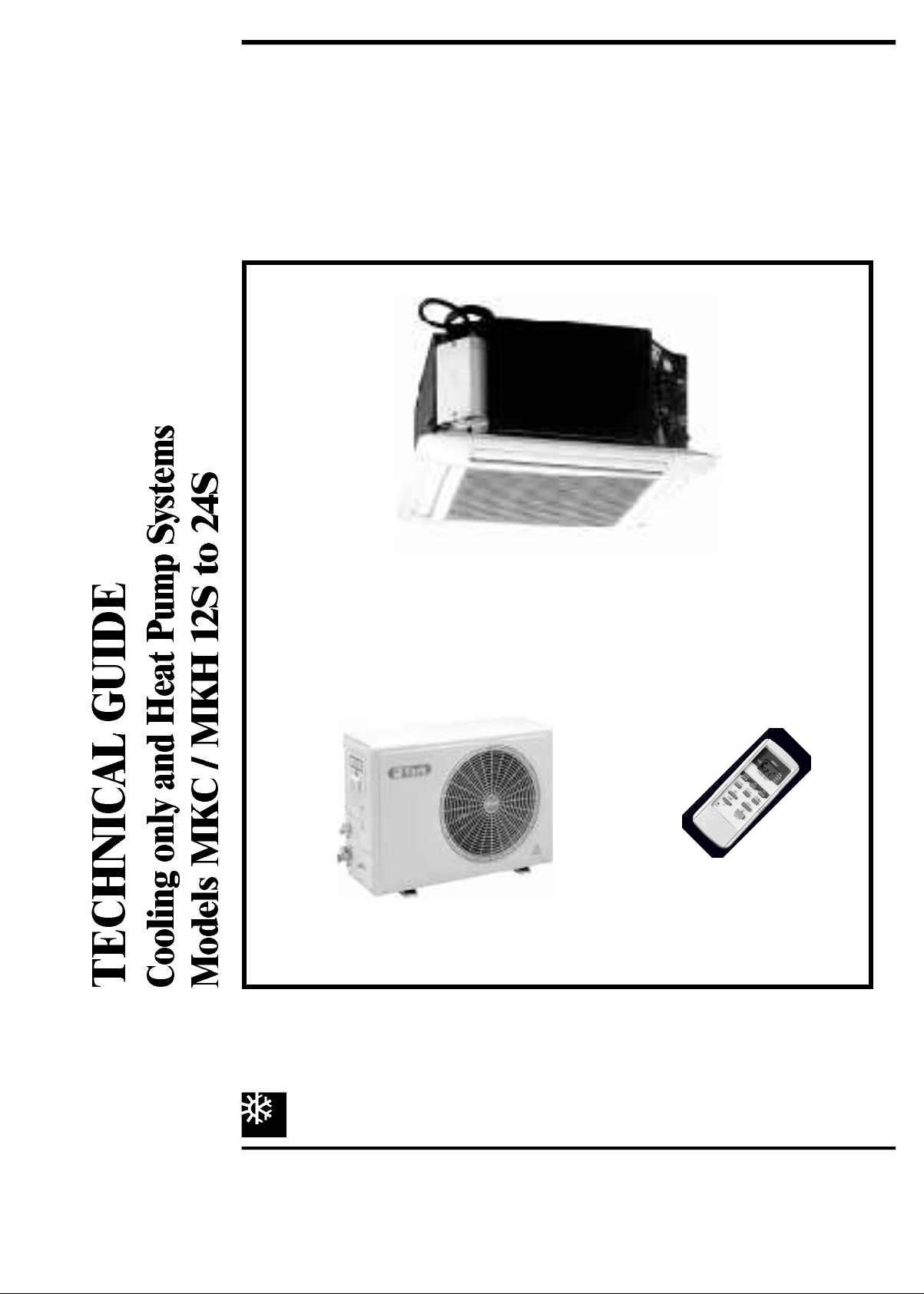
M I N I S P L I T
MKC / MKH 12-18-24
Infrared remote
control
MOC / MOH
YORK
®
<--
Cassette
Page 2
List of Contents
<--
Page
1 - Safety...................................................................................................................................................................................3
2 - Indoor and outdoor onits......................................................................................................................................3
2.1 - Indoor unit ...........................................................................................................................................................3
2.2 - Panel with return grille for indoor unit..........................................................................................3
2.3 - Outdoor unit.......................................................................................................................................................3
2.4 - Auto restart and anti freeze protection.......................................................................................3
3 - Technical specifications........................................................................................................................................3
4 - Dimensions.....................................................................................................................................................................4
5 - Installation........................................................................................................................................................................5
6 - Condensate drainage.............................................................................................................................................6
7 - Refrigerant piping connections.......................................................................................................................7
8 - Wiring diagram.............................................................................................................................................................8
9 - Front panel installation..........................................................................................................................................8
10 - Maintenance...............................................................................................................................................................10
11 - Technical appendix................................................................................................................................................10
Parts List: (Contact York)
Decommissioning, Dismantling and Disposal
Installation and maintenance of this air conditioning system
should only be carried out by trained and qualified personnel.
Regular maintenance operations such as cleaning the coils and
air filters must be performed to keep the units in proper
operating condition.
CAUTION
Before undertaking any work on the unit, make sure that the
power supply has been disconnected.
2
1 - Safety
ELECTRICAL CONNECTIONS
All electrical wiring and connections must comply with local
standards.
GENERAL PRECAUTIONS
Check that the power supply available agrees with nameplate
voltage.
Use adequate line protection.
The unit must be grounded.
Page 3
2 - Indoor & outdoor units
<--
2.1 - Indoor unit
Each unit is shipped with the following items:
- an indoor unit ready for connection to the condensing unit,
- mounting brackets,
- a technical tuide,
- a user's tuide,
- an infrared remote control with a wall bracket and 2 batteries,
- a cut-out template for the casing printed on the cassette
packing box.
2.2 - Panel with return grille for indoor unit.
3 - Technical specifications
2.3 - Outdoor unit
The units are shipped complete with a charge of R22 refrigerant
sufficient for a piping length of 7.5 metres.
2.4 - Auto restart and anti freeze protection
- After a power failure, the unit restarts automatically (when
power is resumed) in the same mode.
- When evaporator surface temperature is –2°C, the compressor
is stopped, the fan continues to run. Compressor operation is
resumed when temperature rises to 0°C.
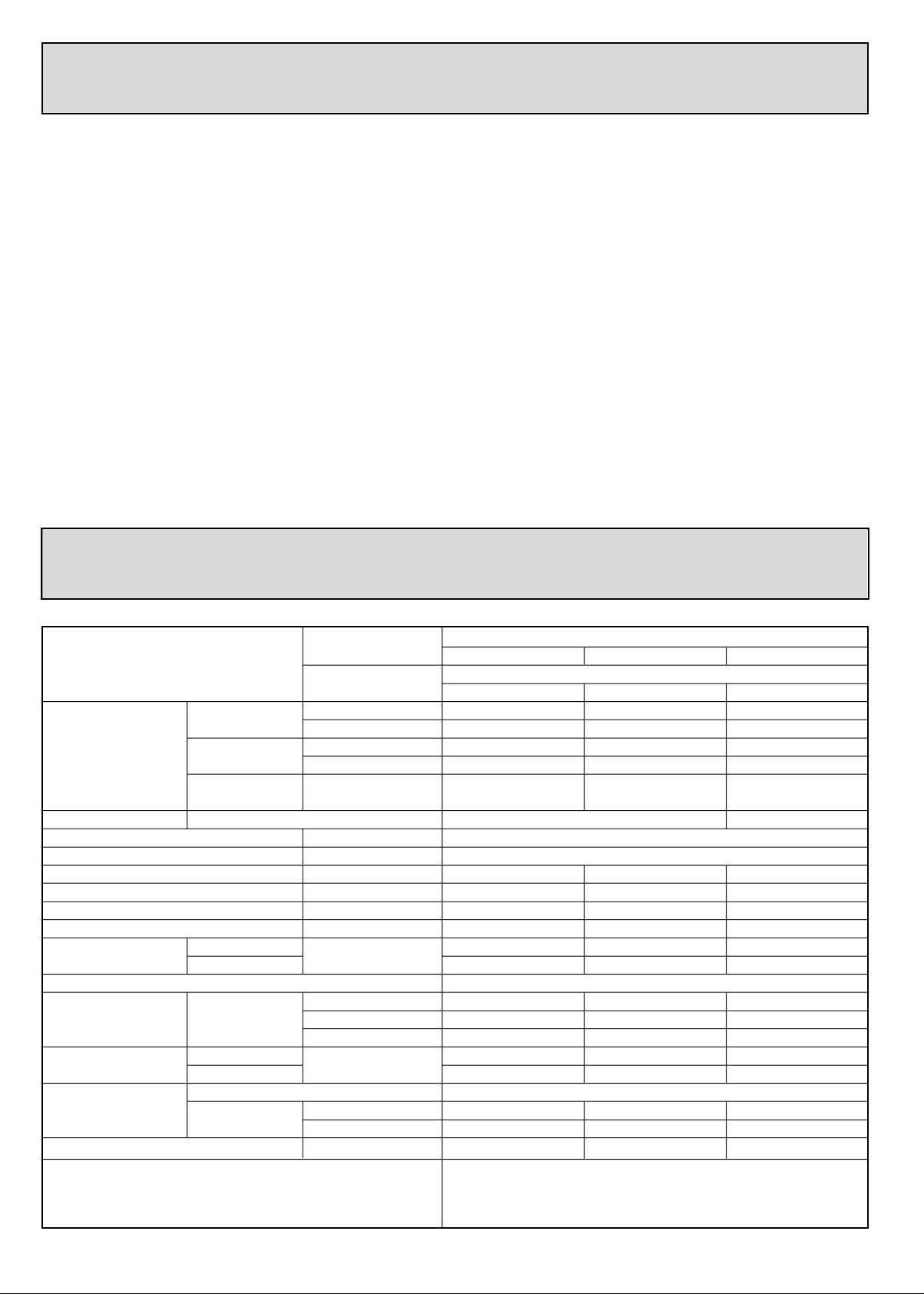
Indoor MKC - MKH
Models unit 12S 18S 24S
Outdoor MOC - MOH
unit 12 18 25
Cooling
Capacities
Compressor Type Rotary Reciprocating
Refrigerant R-22
Power supply V/Ph/Hz 220/240-1-50
Power input kW 1.3 2 2.8
Nominal current A 6.3 9.4 13
Current draw (Electric heat) A 9.1 9.1 9.1
Indoor air flow m3/h 640 850 950
Noise level at 3m
Operating controls Wireless remote control
Dimensions Indoor/Outdoor W (mm) 575/764 575/820 575/850
Net weight
Piping
Dehumidification l/h 1.7 2.5 3.2
Heating
Electric heating
(option)
Indoor
Outdoor
Indoor
Outdoor 38 59 65
Type of connection Flared
Diameter
Btu/h 12 000 18 000 24 000
kW 3.5 5.3 7
Btu/h 12 500 18 500 25 100
kW 3.6 5.4 7.1
kW 2 2 2
dBA
H (mm) 300/492 300/590 300/696
D (mm) 575/230 575/280 575/287
kg
Gas 1/2" 5/8" 5/8"
Liquid 1/4" 3/8" 3/8"
18/24/27 26/30/33 32/36/38
37 55 56
20 22 24
Nominal cooling capacity based on : Nominal heating capacity based on :
- Indoor air temp. 27°C DB/19°C WB - Indoor air temp. 21°C DB - Outdoor air temp. 7°C DB/6°C WB
- Outdoor air temp. 35°C DB Piping length : 7.5 m
3
Page 4
4 - Dimensions
H
L
P
1
660
<--
660
3
2
5
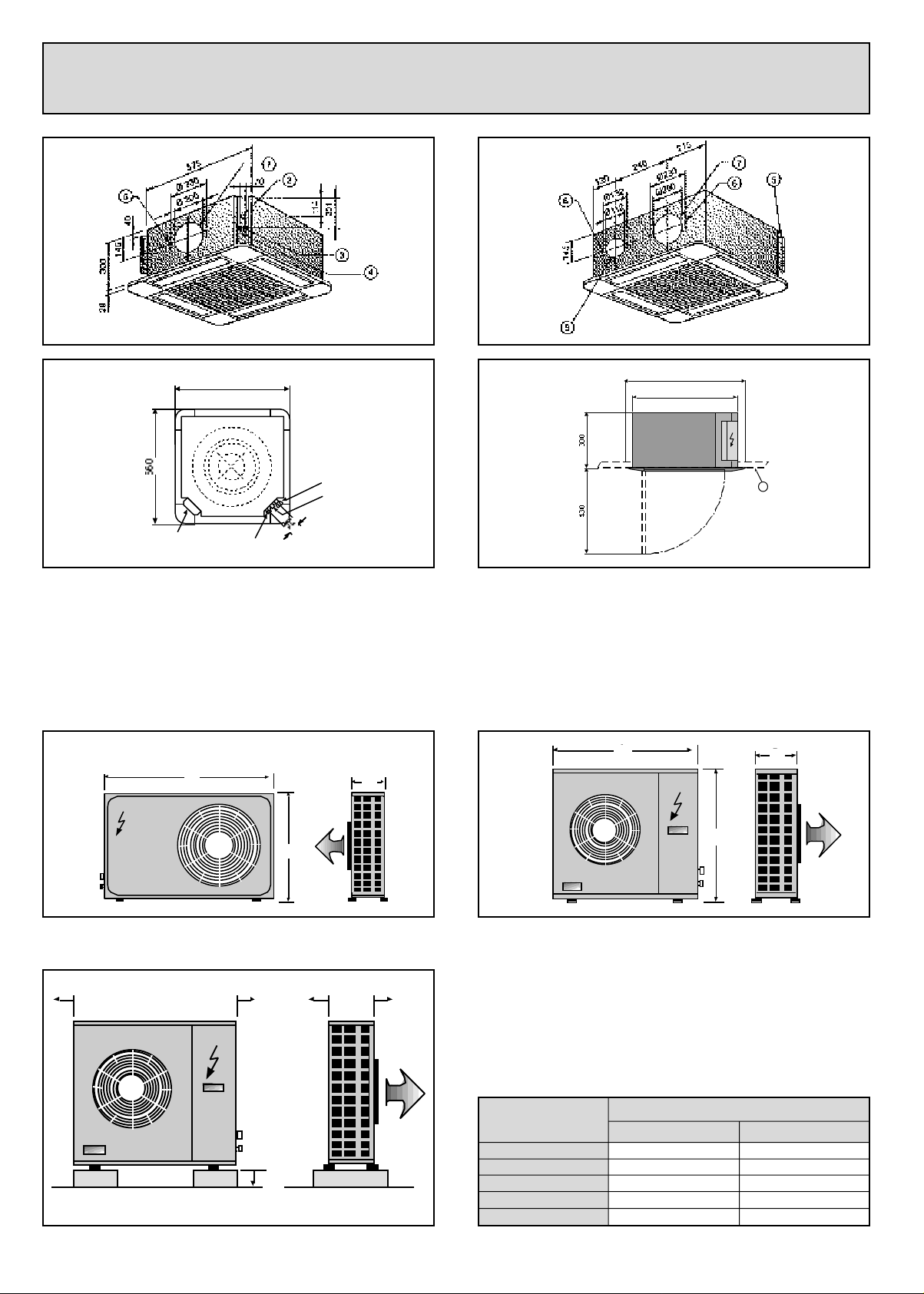
1. False ceiling
2. Condensate drainage
3. Gas line connection
4. Liquid line connection
5. Removable electrical box
4
6. Holes ø 2,9 mm
7. Pre-stamped knock-out for remote air discharge
8. Pre-stamped knock-out for outdoor air intake
Note: An outdoor air grille and an air filter must be used with the
outdoor air intake.
Outdoor unit: MOC/MOH 12-18 Outdoor unit: MOC/MOH 25
W
W
D
575
D
Clearances required for outdoor units
4
H
B EA D
C
Unit dimensions are shown in the technical characteristics
table on page 3.
Unit Clearances
A minimum of clearance is necessary around the units to ensure proper air circulation and easy access for maintenance.
MOC - MOH
12-18 25
A 200 200
B 400 400
C 100 100
D 200 250
E 600 600
Page 5
5 - Installation
<--
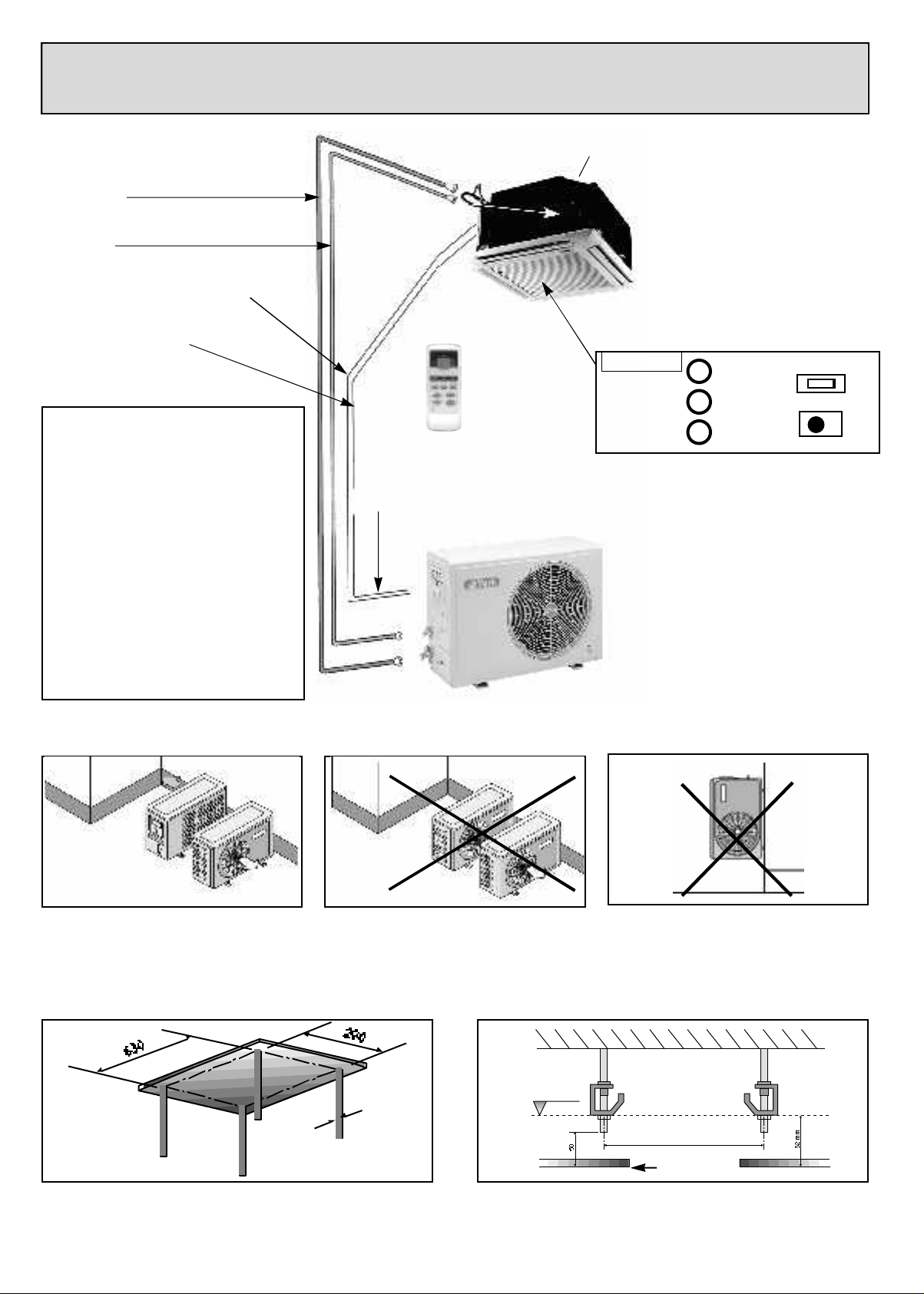
• Connections
Suction line
Liquid line
Electrical connections between sections
Electric heat supply (option)
Optional electric heating coil AKR01A (2kW) :
MKC (cooling only) : The heating element, installed around the coil like a belt, is activated by a
relay located on the control board. Installation of
this option requires no particular modification of
the equipment.
MKH (heat pump) :The heating element is acti vated by a relay located on the control board.
Installation requires a separate power supply
with 3 x 1,5 mm2conductors for the 2 kW heating
element.
In this instance, the heating element serves as a
backup heating source (1
2ndstage :
according to the temperature difference between
the setpoint and the return air temperature.
The heater element is supplied with an automatic reset control thermostat and a manually reset
high temperature safety device.
ELECTRIC HEATER
str
stage :
COMPRESSOR
) and is regulated
Condensate water evacutation
Indoor unit
Infrared receiver board located behind the air
return grill.
View :
Connectors
Remote control
LED : OPE : Unit startup.
Main electrical power supply
-
Outdoor unit
POWER : Unit power-up.
TIMER : Timer mode.
Emergency operation : Enables the unit to
be used without the remote control.In this
case, set the selector to "COOL" or "HEAT"
(MKH only) depending on the operating mode
required. The "OPE" LED flashes continuously when the unit is operated this way, and the
remote control is forced off-line. The temperature setpoint is set at 24°C both in the heating
and cooling mode. To revert to normal remote
control operation, set the selector to the
"NOR" position.
OPE
POWER
TIMER
COOL NOR HEAT
IR
• Outdoor unit installation
OK
• Location of the indoor unit
The unit should be installed in such a way that airflow around the
room is not hindered in any way. If possible, install the cassette
unit in the centre of the room (leave at least one meter of clearance on all sides of the unit).
ø8
Air diffusion will be less efficient if the ceiling is at a height greater than 3 metres.
The cassette unit is fixed in place with two brackets and four
threaded rods (see diagram below).
630
False ceiling
The two brackets must be installed perfectly level.
When the cassette is in place on its supports, connect the refri-
geration lines, the electrical power supply and the condensate
drainage line.
5
Page 6
6 - Condensate drainage
<--
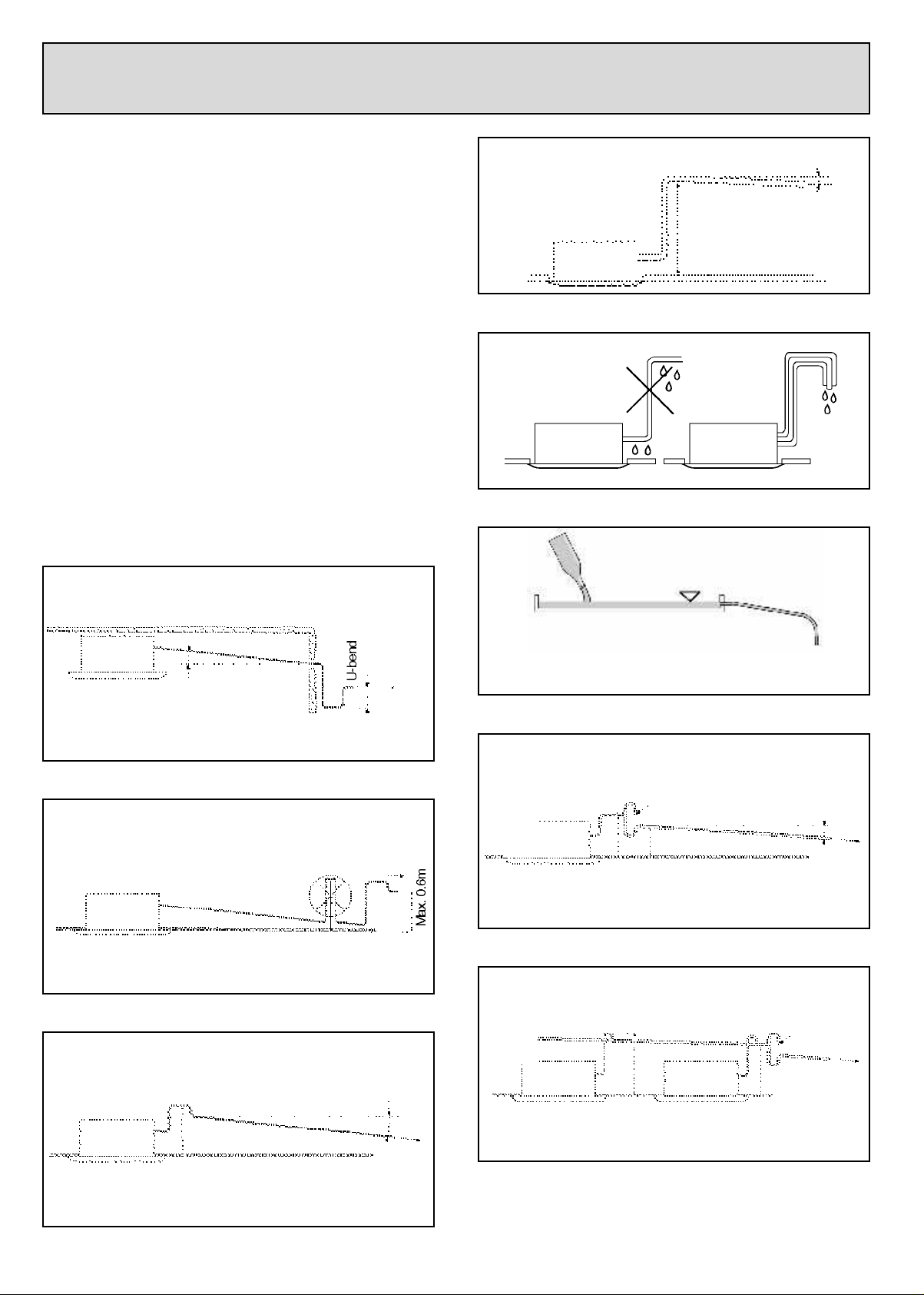
Condensate drainage
Condensates collected in the drain pan are piped to a tank fitted
with :
- a drainage pump, with a pumping height of 0.6 m measured
from the base of the cassette unit (see diagram opposite),
- a safety float switch that stops the entire unit in the event of a
problem with condensate drainage (pump failure, obstructed
drainage piping...).
The condensate drainage line must be insulated to prevent droplets of condensation from dripping on the false ceiling.
Connect the drainage tube (ø int. 12 mm) coming from the pump
to a "P. V.C." drainage line (ø 32 mm mini). It is advisable to install
a U bend in the drainage line.Make sure that all piping joints are
leak tested.
Drainage piping should be installed with a 1% downward slope
(1cm per metre) without any rises.
1%
Max. 0.6 m
Gradient > 1%
Verification of condensate water drainage:
Fill the drain pan and observe evacuation.
Gradient > 1%
Max.0.6m
Fill the drain pan manually with water to check correct
evacuation.
6
Page 7
7 - Refrigerant piping connections
<--
Make piping runs as short as possible and avoid all
unnecessary changes in direction or elevation.
To prevent heat loss, the two lines must be insulated
s e p a r a t e l y.
Use an appropriate bending tool to form curves and avoid
flattening the refrigerant tubes.
Fix piping with pipe clamps and make sure that any eventual
pipe vibrations cannot be transmitted to the building structure.
Use refrigeration quality piping only with an operating pressure rating of at least 30 bars. N e v e r use ordinary «plumbing» quality piping : you MUST use special de-oxidised,
dehydrated, refrigerant quality copper piping.
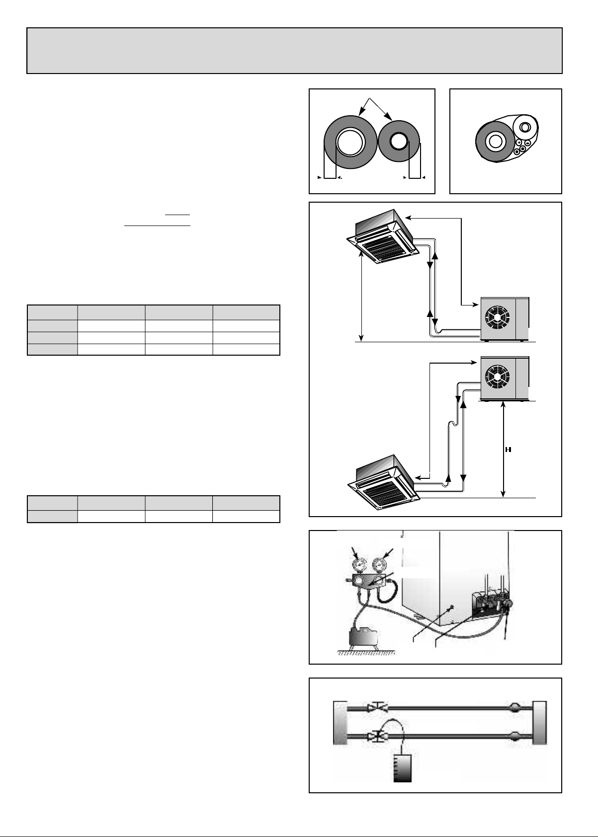
Pipe lengths
• Maximum piping lengths
Unit size
D (m) 15 15 22
L (m) 18 18 25
H (m) 12 12 20
Note: Where the difference in elevation between the indoor
unit and the outdoor unit is greater than 5 metres, install
an oil trap every 5 metres.
The suction line must have a 2% gradient up to the compressor
on horizontal sections.
Where piping lengths are unusually long and include a large
number of oil traps, it may be necessary to adjust the compressor oil charge.
12 18 25
• Refrigerant charge to be added per extra metre of
piping length when more than 7.5 m.
Insulation
Minimum thickness 6 mm
Heat pump
D
Liquid
Cooling
Heat pump
(discharge)
Gas
Heat pump
L
(discharge)
Gas
L
Cooling
(suction)
Heat pump
Liquid
Cooling
Unit size 12 18 25
g/m 15 40 40
Refrigerant piping connections (FLARE connections)
To avoid alteration of unit capacities, make sure that piping
lengths and changes in elevation are kept to a strict minimum.
Before connecting the refrigerant lines, follow the procedures
below (if pre-charged connection lines are not supplied) :
- Select copper pipe diameters according to the size of unit to
be installed.
- Install the refrigeration lines, making sure that no foreign
bodies get inside the piping.
- Install the flare connectors and flare the ends of the pipes.
- Evacuate the piping. This operation, which should last at
least 15 minutes or even longer if there are large piping
lengths and changes in elevation, should be followed by a
leak test. To this effect, when the piping has been evacuated, close the pressure guage tap, note the value on the
guage, then wait for 15 minutes. If the needle moves, there
is a leak in the system. Make the necessary adjustments or
repairs and repeat this procedure until the needle no longer
m o v e s .
- Open the service valves and top up the refrigerant charge if
n e c e s s a r y.
Low pressure
High pressure
Manifold
Pressure
tap
R22
Cooling
(suction)
Liquid valve
Gas line
Liquid line
Gas valve
Indoor unitOutdoor unit
7
Page 8
8 - Wiring diagram
<--
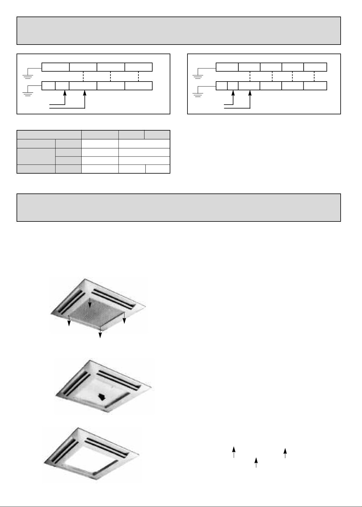
Cooling only units - MKC
1NE 2
Indoor unit
1NE A 2
Outdoor unit
Power supply
220V/1Ph/50Hz
Wiring sizes
Unit size 12 18 25
Power supply mm
Interconnection Cool. mm23 x 2.5 + ground 3 x 1.5 + ground
( I n d o o r / O u t d o o r ) Heat. mm24 x 2.5 + ground 4 x 1.5 + ground
Fuse (Slow-blow) A 10 16 20
2
3 x 2.5 3 x 4
9 - Front panel installation
Heat pump units - MKH
1NE 2
Indoor unit
1NE A 2
Power supply
220V/1Ph/50Hz
For details of indoor and outdoor unit wiring, see the diagram
supplied inside the units. Start the unit and check operation both
in cooling and heating mode.
3
3
Outdoor unit
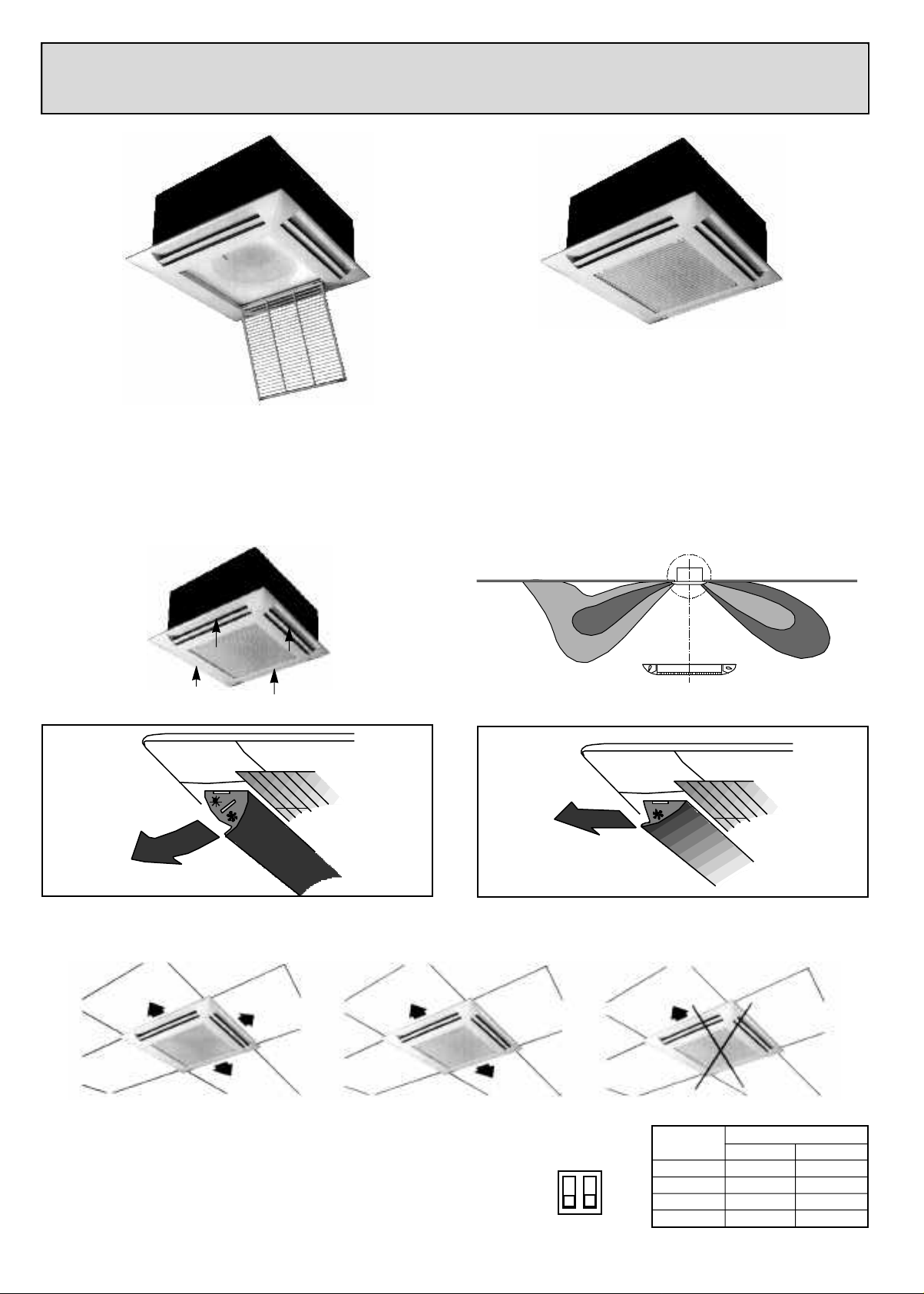
Installing the "diffuser-grille" assembly
• Mounting
- Remove the return air grill by springing the 4 mounting clips
and 2 hinges (fig. 1, ref. a).
- Remove the air filter (fig. 2 & 3).
Fig. 1
a
a
a
Fig. 2
a
- Put the grill in place under the cassette chassis (fig. 4).
- Connect the panel heater wires.
- Fit the casing and grille together using the screws (fig. 5, ref. b).
- Put the filter (fig. 6) and the return air grille (fig. 6 & 7) back in
place.
Fig. 4
Fig. 5
Fig. 3
b
b
b
8
b
Page 9
9 - Front panel installation (cont’d)
A
<--
Fig. 7Fig. 6
Directing the airflow
With direct air discharge, pay particular attention to the direction
in which the air is discharged.
• Air deflectors (ref a)
These deflectors should be directed so that a maximum volume is
given to the envelope of the airstream. Below, the diagram shows
the optimum position required to acheive the best possible airflow
performance.
a
a
a
a
• Integral diffuser
In the cooling mode, cool air is discharged horizontally just below
the ceiling, ensuring even air distribution in the room due to the
«coanda» effect without causing drafts.
In the heating mode, airflow can be directed so as to prevent stagnation at certain places in the room (stratification of hot air).
Heating operation (winter)
Detail A
Cooling operation (summer)
Coanda effect
Winter position
Depending on the configuration of the room to be air conditioned,one or two of the deflectors may be left closed.
Depending on the layout of the conditioned space, 1 or 2 dampers may be closed. This is necessary for air discharge through a
discharge satellite into an adjacent room or when the cassette unit is installed too close to a wall.
Summer position
YES YES NO
Temp. Switch
Operation in heating mode only : Although the unit has an anti-stratification
function, it may be necessary to offset the return air sensor setpoint, in cases
where ceilings are particularly high for example. This can be done with the two
microswitches on the control board. Setpoint offsetting is only effective in the
heating mode and has no effect on the cooling mode.
ON
OFF
1 2
difference °C 2 1
0 OFF OFF
1 OFF ON
3 ON OFF
5 ON ON
9
Page 10
10 - Maintenance
<--
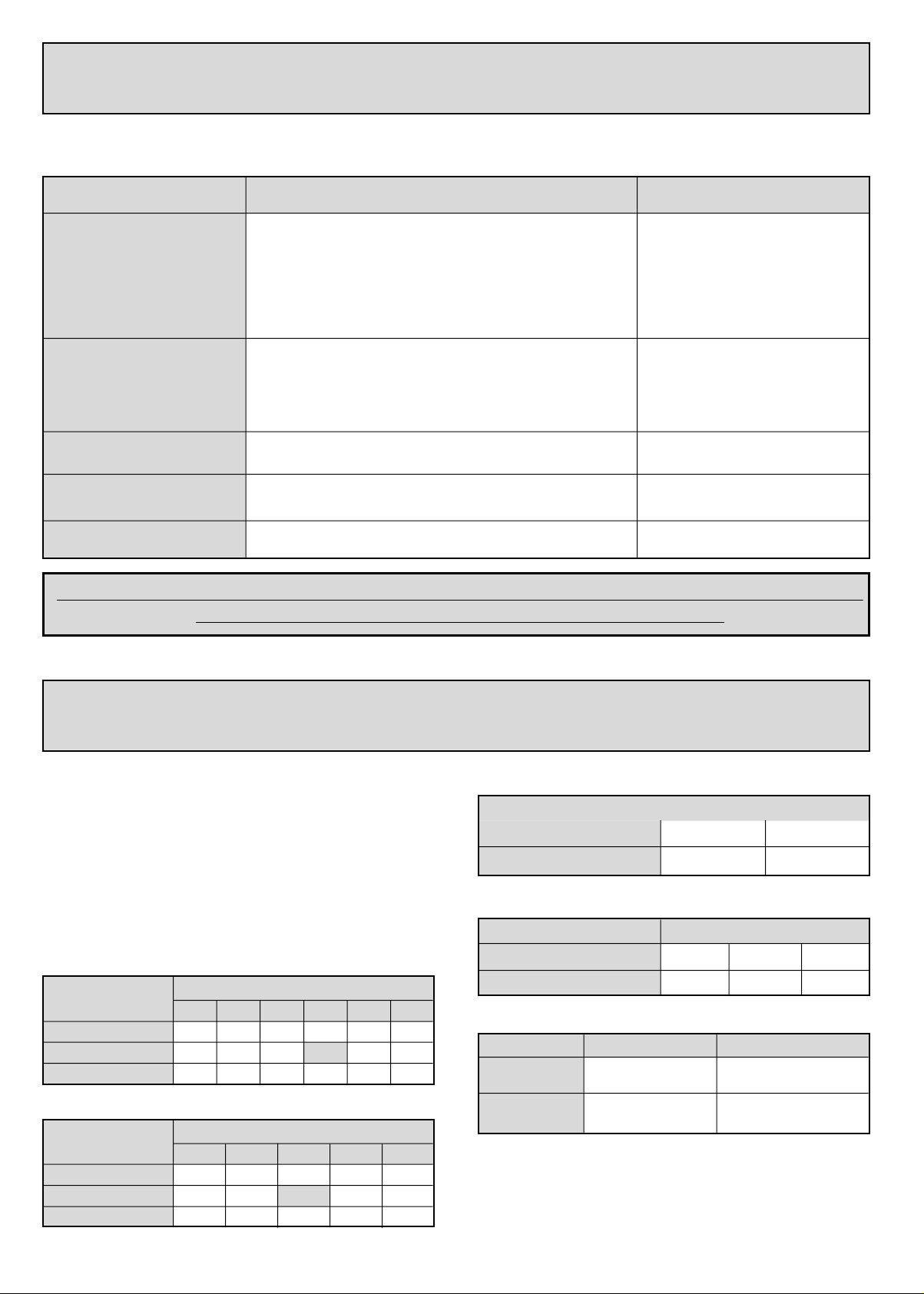
The units are designed to operate for long periods of time with a minimum of maintenance. However, the following operations must be
performed regularly.
Component Maintenance operation Recommended frequency
Air filter 1 - Clean with a vacuum cleaner or tap gently then Every month or more
wash in warm water (40°C) with a mild detergent. often if necessary.
2 - Rinse and dry before replacing on unit.
3 - Never use petrol, alcohol or any other chemical
product.
Unit casing 1 - Remove dust from the front panel with a soft duster Every month or more
or wipe a damp cloth with a mild soap solution. often if necessary.
2 - Never use petrol, alcohol or any other chemical
product.
Drain pan and 1 - Clean and check for obstructions. Each season before start up.
evacuation piping
Indoor / outdoor coils 1 - Check condition and remove dust from between Each season before start up.
coil fins.
Compressor 1 - No maintenance required.
A L L O T H E R SERVICE AND MAINTENANCE OPERATIONS MUST BE PERFORMED BY TRAINED
AND QUALIFIED PERSONNEL APPROVED BY THE SUPPLIER
11 - Technical appendix
Unit Capacity
Total cooling capacity can be determined by using correction fac-
tors C1, C2 and C3.
Given cooling capacity = Cooling capacity at standard rating
conditions x C1 x C2 x C3.
C1 = Capacity correction factor for temperature
C2 = Capacity correction for piping length
C3 = Capacity correction for indoor unit fan speed
Capacity correction factor for temperature (C1)
Cooling capacity correction factor
Indoor temp. Outdoor temp. °C DB
°C WB 19 25 30 35 40 46
23 - 1.20 1.15 1.11 1.06 1
19 1.10 1.08 1.04 1 0.96 0.90
14 0.88 0.86 0.84 0.82 0.79 0.74
Heating capacity correction factor
Indoor temp. Outdoor temp. °C WB
°C DB 14 10 6 0 -8
23 1.20 1.04 0.96 0.77 0.58
20 1.25 1.10 1 0.80 0.69
17 1.30 1.13 1.04 0.83 0.63
Capacity correction factor for piping length (C2)
Indoor unit
Piping length (m) 7.5 10
Correction factor C2 1 0.98
Capacity correction factor for indoor fan speed (C3)
Unité intérieure
Fan speed High Medium Low
Correction factor C3 1 0.90 0.75
Operating temperature limits
Maximum Minimum
Cooling mode +46°C
Heating mode
* Conditions applicable for the "Low ambient line" / +19°C for the "Export
line".
Correction factors (C1) determine the instantaneous capacity (which
does not take account of defrosting on heat pump units). T h e s e
capacities may vary slightly, depending on the size of the unit.
+28°C
(heat pump mode)
0°C
(-10 with fan stoppage)
-10°C
10
Page 11
CONFORMITY DECLARATION
<--
FOR MACHINES
WE: C.R. YORK, S.L.
PASEO ESPRONCEDA, 278, 08.204 SABADELL
DECLARE UNDER OUR OWN RESPONSIBILITY THAT THE MACHINE:
DESIGNATION: Air conditioning
TYPE: MKC 12-18-24 & MKH 12-18-24
SERIAL NUMBER:
IS IN COMPLIANCE WITH THE REQUIREMENTS OF:
• APPLICABLE EEC DIRECTIVES 89/392/EC, 89/336/CEE
• NATIONALSTANDARDS AND TECHNICAL SPECIFICATIONS ISO 9001, (Pr EN378)
AND IN ACCORDANCE WITH THE FOLLOWING HARMONIZED STANDARDS
• EN60204-1, EN292-1, EN292-2, EN563, EN294, EN953, EN55014, EN60555-2,
EN50082-1
NAME : SERRA
SURNAME : Ignari
POSITION : Quality Manager
SIGNATURE :
Page 12
DE-COMMISSIONING DISMANTLING & DISPOSAL
<--
This product contains refrigerant under pressure, rotating parts, and electrical connections which may be a danger and cause injury !
1. Isolate all sources of electrical supply to the unit including any control system supplies switched by the unit. Ensure that all points of electrical
2. Remove all refrigerant from each system of the unit into a suitable container using a refrigerant reclaim or recovery unit. This refrigerant may
3. Packaged units can generally be removed in one piece after disconnection as above. Any fixing down bolts should be removed and then the
4. After removal from position the unit parts may be disposed of according to local laws and regulations.
All work must only be carried out by competent persons using suitable protective clothing and safety precautions.
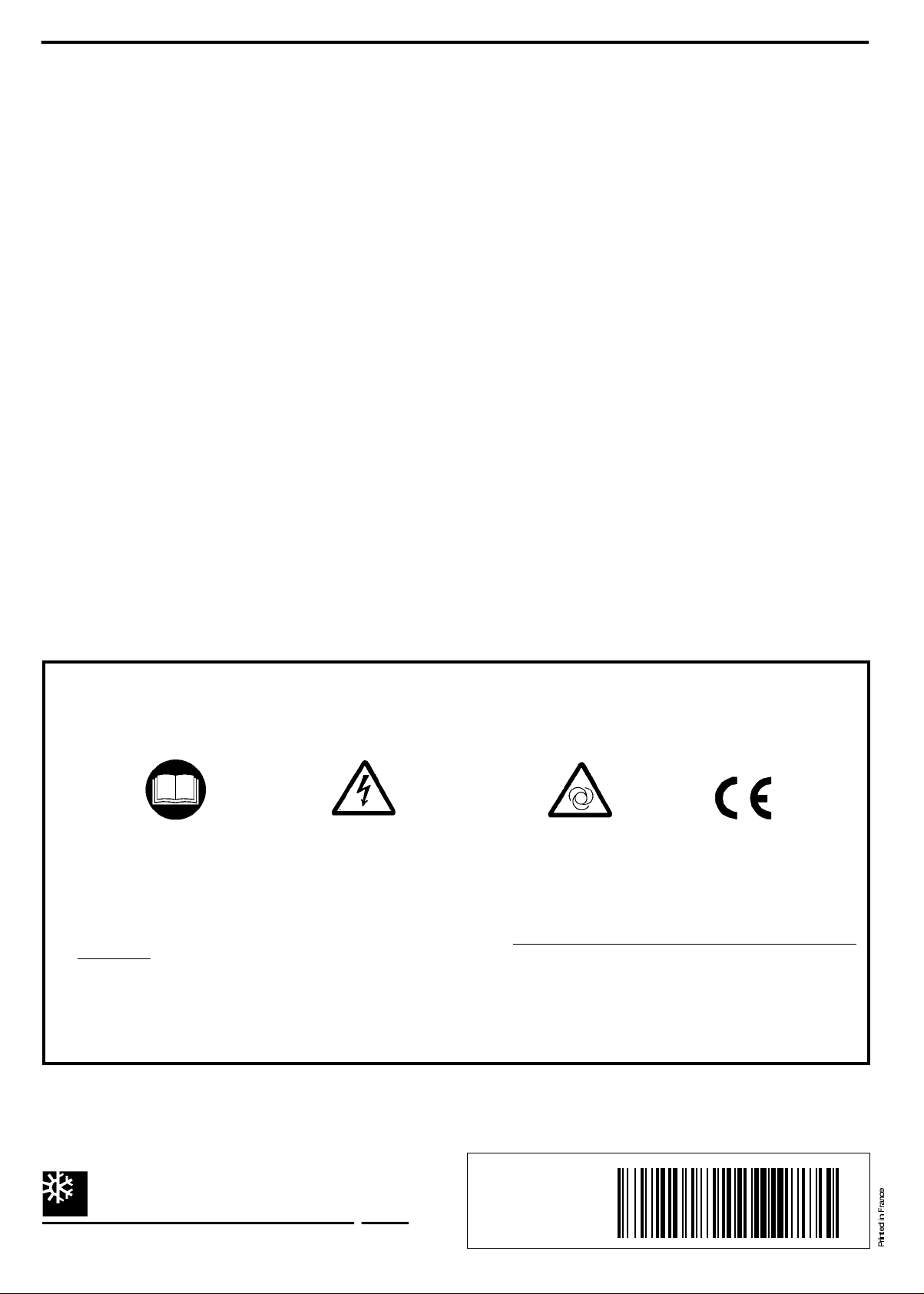
Read the Manual Risk of electric shock Unit is remotely controlled and
may start without warning
and gas isolation are secured in the OFF position. The supply cables and gas pipework may then be disconnected and removed. For points of
connection refer to unit installation instructions.
then be re-used, if appropriate, or returned to the manufacturer for disposal. Under NO circumstances should refrigerant be vented to
atmosphere. Where appropriate, drain the refrigerant oil from each system into a suitable container and dispose of according to local laws and
regulations governing disposal of oily wastes.
unit lifted from position using the points provided and equipment of adequate lifting capacity. Reference MUST be made to the unit installation
instructions for unit weight and correct methods of lifting. Note that any residual or spilt refrigerant oil should be mopped up and disposed of as
described above.
®
YORK
YORK INTERNATIONAL
Europe
E - TEC - M9910
Manufacturer reserves the right to change specifications without prior notice.
 Loading...