

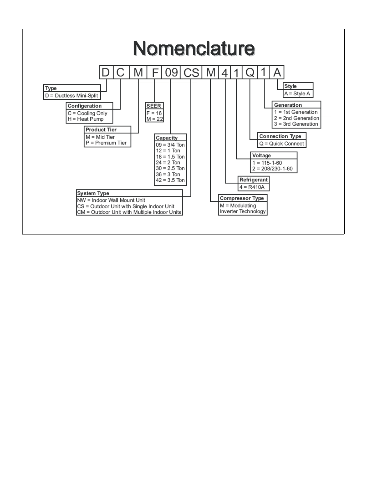
Page 1
LX SERIES
DUCTLESS SINGLE-SPLIT
AIR CONDITIONERS AND HEAT PUMPS
16 SEER – 1 PHASE
3/4 THRU 2 NOMINAL TONS
MODELS: DCMF/DHMF
Due to continuous product improvement, specifications
are subject to change without notice.
Visit us on the web at
www.upgnet.com
Additional rating information can be found at
www.ahridirectory.org
WARRANTY SUMMARY*
Standard 2-Years limited parts warranty.
Standard 6-Years limited compressor warranty.
TECHNICAL
GUIDE
TECHNICAL
GUIDE
FOR DISTRIBUTION USE ONLY - NOT TO BE USED AT POINT OF RETAIL SALE
923178-UTG-B-0114
DESCRIPTION
The Single-Split Series are ductless climate systems. They are
designed with a matching indoor unit for optimum performance and efficiency. These climate systems are supported with accessories and documents to serve specific functions.
FEATURES
Variable Frequency Rotary Compressor - Twin rotary in ve rte r co mpressor
on all models features high efficiency operation that modulates down to 15
Hz and as high as 120 Hz for red uced vibrat ion and qu iet opera tion. Brus hless DC motor uses powerful Neodymium magnets that are approximately
15-20 times stronger than ferrite magnets used in conventional AC compressors. The DC Inverter Control provides continuous operation, while adjusting
capacity according to room temp eratur e. Th e accur ate s ensing of co oling or
heating loads prevents frequen t changes in capacity and ensur es efficient,
economical operation.
Low Ambient Cooling Operation Down to 5 °F - This feature allows for a
space to be air-conditioned eve n in outdoor temperatures as low as 5 °F.
This cooling ability is important when de aling with server equipment rooms,
surveillance mechanical rooms, restaurant kitchens, fitness centers, and
more.
Load Variat io n Mana ge ment S ys tem - The outdoor coil thermistor continuously monitors the temperature and commun icates wit h the micro process or.
Depending on the temperature measured, the compressor will be allowed to
increase the frequency if nee ded to meet the load or reduce frequen cy as
the load is reduced.
High Pressure Discharge Temperature - The compressor discharge li ne
thermistor continuously monitors the temperature and communicates with
the microprocessor. Depending on the temperatur e me as u red, the compressor will be allowed to in crea se t he f r equen cy t o me et th e lo ad o r is fo rc ed to
run at the current or reduced f requency. If the temperature gets excessi vely
high, the compressor will be de-e nergized.
Defrost Control (Heat Pump Models) - Defrost cycle is automatically
enabled if there is a build-up of frost on the outdoor coil. Outdoor fan and
indoor blower operation is terminated during the defrost cycle. H1 is displayed on the indoor unit panel on the front cover during a defrost cycle.
Reversing Valve (Heat Pump Models) - 4-way inter change reversing valve
effects a rapid change in direction of refrigerant flow resulting in quick
changeover from cooling to h eating and vice vers a. Valve operates on system pressure differential betw e en outdoor unit and indoor unit.
R-410A Refrigerant - Unit is pre- charged with R410A refrigerant that uses
PVE refrigerant oil. Polyvinyl ether (PVE) is an innovative refrigerant oil specially formulated for hydrofluorocarbon (HFC) refrigeration systems. In addition to providing lubricati ng propert ies, it al so has a nu mber of othe r applied
advantages that help to increase the reliability of the refrigeration systems
where it is applied.
Refrigerant Line Connections, Service Valve - Outdoor units are designed
with easy service and mai nten an ce in mi n d. Ma in te nanc e p oi nts are loc at ed
behind easy-access panels, to m ake installation and s ervice a breeze for a
trained technician. Flare connection lines are located on side of unit cabinet.
Fully serviceable brass service valve prevents corrosion an d provide access
to refrigerant system. Shut -off valve that can be fully shut off while 2-way
suction/vapor valve (with service port) may be front seated to manage refrigerant charge while servicing system.
Air Deflection Louvers - Horizontal louvers default to the cooling or heating
position when the unit i s operating. Horizontal louvers can be set to a preset
oscillating range or fixed position from the wireless remote control. Full oscillating is the default settin g when button is pushed. Vertical louvers can be
manually adjusted to direct th e airflow for optimal comfort.
Indoor Coil Freeze Protectio n - The indoor coil thermistor monitors the coil
temperature continuously. Any time the coil tempera ture drops below 30°F,
the compressor and the outdoor fan (30 secon ds later) will be switched off
until the coil temperature r ises above 43°F and the compressor has been off
for a minimum of 3 minutes.
I FEEL Function - When I FEEL is activated, the system will sat isfy the coo ling or heating temperature setpoint where the remote control is located.
When I FEEL is deactivated, th e system will satisfy the cooling or heating
temperature setpoint where the indoor u nit is lo cated. This feature pr ovides
homeowners with optimum comfort whether the y are near or far from the
indoor unit.
Hot Heat Pump (cold air prevention) - In heating mode, the indoor fan wil l
be delayed from 1 to 3 minutes to allow refrigerant to warm up and avoid
cold blow. This may occur during:
• Initial start-up of a heating cycle
• Immediately after completion of an Auto mode operation
• Heating under extremely low indoor temperatures
Page 2
923178-UTG-B-0114
2 Johnson Controls Unitary Products
Page 3
923178-UTG-B-0114
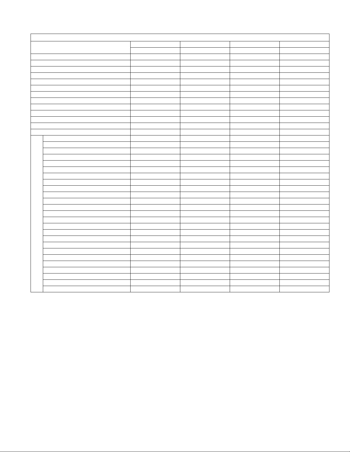
SPECIFICATIONS
AIR CONDITIONERS
Model (Indoor/Outdoor)
Function Cooling Cooling Cooling Cooling
Rated Voltage 208/230 208/230 208/230 208/230
Frequency (Hz) 60Hz 60Hz 60Hz 60Hz
Total Capacity (BTUH) (High/Standard/Low) 11500/9000/3800 12500/12000/3300 21000/18000/4500 24000/22000/6400
Total Capacity (W) (High/Standard/Low) 3370/2637/1114 3663/3516/967 6155/5276/1319 7032/6446/1875
Rated Power Input (W) 882 1224 1621 2200
Nominal Input Current (A) 4.01 5.56 7.37 10.00
SEER 16.00 16.00 16.00 16.00
Air Flow Volume (CFM) (H/M/L) 330/300/260/210 340/300/260/210 470/400/330/270 590/440/300/200
Air Flow Volume (m3/h) (H/M/L) 560/510/440/370 580/520/440/370 800/680/560/460 1000/750/520/350
Dehumidifying Volume (cu.ft./h) 0.028 0.049 0.064 0.075
Dehumidifying Volume (l/h) 0.80 1.40 1.80 2.13
EER 10.2 9.8 11.1 10
Model of Indoor Unit DCMF09NWM42Q1 DCMF12NWM42Q1 DCMF18NWM42Q1 DCMF24NWM42Q1
Fan Motor Speed (r/min) (SH/H/M/L) 1300/1100/900/700 1350/1150/950/750 1400/1150/1000/850 1450/1180/1000/850
Output of Fan Motor (w) 15 15 20 36
Fan Motor Capacitor (uF) 1.2 1.2 1.5 2.5
Fan Motor RLA (A) 0.19 0.19 0.32 0.45
Fan Type-Piece Cross-flow - 1 Cross-flow - 1 Cross-flow - 1 Cross-flow - 1
Diameter-Length (inch) 3.6 × 23.4 3.6 × 23.4 3.9 × 25.6 3.9 × 30.1
Diameter-Length (mm) 92 × 594 92 × 595 98 × 650 98 × 765
Evaporator Aluminum Fin-copper Tube Aluminum Fin-copper Tube Aluminum Fin-copper Tube Aluminum Fin-copper Tube
Pipe Diameter (inch) Φ 0.276 Φ 0.276 Φ 0.276 Φ 0.276
Pipe Diameter (mm) φ7 φ7 φ7 φ7
Row-Fin Gap (inch) 2 - 0.055 2 - 0.055 2 - 0.055 2 - 0.059
Row-Fin Gap (mm) 2-1.4 2-1.4 2-1.4 2-1.5
Coil length (L) x height (H) x coil width (W) (inch) 24.0 × 11.6 × 0.9 24.0 x 11.6 × 0.9 25.9 × 12.0 × 1.0 30.1 × 13.5 × 1.0
Indoor Unit
Coil length (L) x height (H) x coil width (W) (mm) 610 × 24 × 294 610 × 24 × 294 657 × 25.4 × 304.8 765 × 25.4 × 342.9
Output of Swing Motor (W) 1.5 1.5 2 3
Fuse (A) 3.15 3.15 3.15 3.15
Sound Pressure Level dB (A)(SH/H/M/L) 43 / 38 / 32 / 26 44 / 39 / 33 / 28 48 / 43 / 38 / 34 49 / 43 / 39 / 34
Sound Power Level dB (A)(SH/H/M/L) 53 / 48 / 42 / 36 54 / 49 / 43 / 38 58 / 53 / 48 / 43 59 / 53 / 49 / 44
Dimension (W/D/H) (inch) 30.3 × 7.9 × 11.1 30.3 × 7.9 × 11.1 34.1 × 8.5 × 12.0 39.7 × 8.7 × 12.4
Dimension (W/D/H) (mm) 770 × 201 × 282 770 × 201 × 282 865 × 216 × 305 1008 × 221 × 315
Dimension of Package (L/W/H) (inch) 33.3 × 10.9 × 13.9 33.3 × 10.9 × 13.9 37.3 × 12.2 × 15.1 42.2 × 12.3 × 15.6
Dimension of Package (L/W/H) (mm) 847 × 276 × 352 847 × 276 × 352 948 × 310 × 383 1073 × 313 × 395
Net Weight /Gross Weight (lbs) 19 / 25 20 / 27 27 / 35 33.0 / 44.0
Net Weight /Gross Weight (kg) 8.6 / 11.5 9.0 / 12 12.0 / 16 15 / 20
Continued on next page.
DCMF09NWM42Q1 DCMF12NWM42Q1 DCMF18NWM42Q1 DCMF24NWM42Q1
DCMF09CSM42Q1 DCMF12CSM42Q1 DCMF18CSM42Q1 DCMF24CSM42Q1
Johnson Controls Unitary Products 3
Page 4

923178-UTG-B-0114
AIR CONDITIONERS (Continued)
Model of Outdoor Unit DCMF09CSM42Q1 DCMF12CSM42Q1 DCMF18CSM42Q1 DCMF24CSM42Q1
Compressor Manufacturer/trademark GREE GREE MITSUBISHI SANYO
Compressor Type Inverter Rotary Inverter Rotary Inverter Rotary Inverter Rotary
L.R.A. (A) 16.50 16.50 27 41
Compressor RLA (A) 6.22 6.22 10.86 11.38
Compressor Power Input (W) 950 950 1245 1630
Throttling Method Capillary Capillary Capillary EXV
Working Temp Range (oF) 5 ~ 115 5 ~ 115 5 ~ 115 5 ~ 115
Working Temp Range (°C) -15 ~ 46 -15 ~ 46 -15 ~ 46 -15 ~ 46
Condenser Aluminum Fin-copper Tube Aluminum Fin-copper Tube Aluminum Fin-copper Tube Aluminum Fin-copper Tube
Pipe Diameter (inch) Φ 0.276 Φ 0.276 Φ 0.276 Φ 0.276
Pipe Diameter (mm) φ7 φ7 φ7 φ7
Rows-Fin Gap (inch) 1 - 0.055 2 - 0.055 2 - 0.055 2 - 0.055
Rows-Fin Gap (mm) 1-1.4 2-1.4 2-1.4 2-1.4
Coil length (L) x height (H) x coil width (L) (inch) 25.5 × 20.8 × 0.8 25.5 × 20.8 × 1.5 33.0 × 26.0 × 1.5 33.6 × 26.0 × 1.5
Coil length (L) x height (H) x coil width (L) (mm) 647 × 19.05 × 528 647 × 38.1 × 528 837 × 38.1 × 660 853 × 38.1 × 660
Fan Motor Speed (rpm) 880±20 880±20 690 690
Output of Fan Motor (W) 21 21 60 60
Fan Motor RLA (A) 0.25 0.25 0.62 0.62
Fan Motor Capacitor ( uF) 2 2 3 3.5
Fuse (A) 15A 15A 25A 25A
Air Flow Volume of Outdoor Unit (CFM) 944 944 1887 1887
Air Flow Volume of Outdoor Unit (m3/h) 1600 1600 3200 3200
Fan Type-Piece Axial-flow-1 Axial-flow-1 Axial-flow-1 Axial-flow-1
Fan Diameter (inch) 14.6 14.6 20.5 20.5
Outdoor Unit
Fan Diameter (mm) 370 370 520 520
Defrosting Method Automatic Defrosting Automatic Defrosting Automatic Defrosting Automatic Defrosting
Climate Type T1 T1 T1 T1
Permissible Excessive Operating
Pressure for the Discharge Side (PSI)
Permissible Excessive Operating
Pressure for the Discharge Side (MPa)
Permissible Excessive Operating
Pressure for the Suction Side (PSI)
Permissible Excessive Operating
Pressure for the Suction Side (MPa)
Sound Pressure Level dB (A) 49 52 56 56
Sound Power Level dB (A) 59 62 66 66
Dimension (W/D/H) (mm) 28.0 × 12.5 × 21.7 28.0 × 12.5 × 21.7 37.9 × 15.6 × 27.6 37.9 × 15.6 × 27.6
Dimension (W/D/H) (mm) 711 × 318 × 551 711 × 318 × 551 963 × 396 × 701 963 × 396 × 701
Dimension of Package (L/W/H) (inch) 30.4 × 13.7 × 23.3 30.4 × 13.7 × 23.3 40.4 × 17.9 × 28.9 40.4 × 17.9 × 28.9
Dimension of Package (L/W/H) (mm) 771 × 348 × 592 771 × 348 × 592 1026 × 455 × 735 1026 × 455 × 735
Net Weight /Gross Weight (lbs) 64 / 73 68 / 77 104 / 115 112 / 123
Net Weight /Gross Weight (kg) 29 / 33 31 / 35 47 / 52 51 / 56
Refrigerant Charge (oz) 26.1 35.3 44.1 54.7
Refrigerant Charge (kg) 0.74 1.00 1.25 1.55
MCA 10.0 10.0 15.0 16.0
MOP 15.0 15.0 25.0 25.0
Length (ft) 25 25 25 25
Length (m) 7.5 7.5 7.5 7.5
Gas additional charge (oz/ft) 0.2 0.2 0.2 0.2
Gas additional charge (g/m) 15 15 15 15
Outer Diameter Liquid Pipe (inch) Φ 1/4 Φ 1/4 Φ 1/4 Φ 1/4
Outer Diameter Liquid Pipe (mm) φ6 φ6 φ6 φ6
Outer Diameter Gas Pipe (inch) Φ 3/8 Φ 3/8 Φ 1/2 Φ 1/2
Outer Diameter Gas Pipe (mm) φ9.52 φ9.52 φ12 φ12
Connection Pipe
Max Height Distance (ft) 32.8 32.8 32.8 32.8
Max Height Distance (m) 9.9 9.9 9.9 9.9
Max Length Distance (ft) 49.2 49.2 82 82
Max Length Distance (m) 14.9 14.9 24.9 24.9
624 624 624 624
4.3 4.3 4.3 4.3
363 363 363 363
2.5 2.5 2.5 2.5
4 Johnson Controls Unitary Products
Page 5
923178-UTG-B-0114
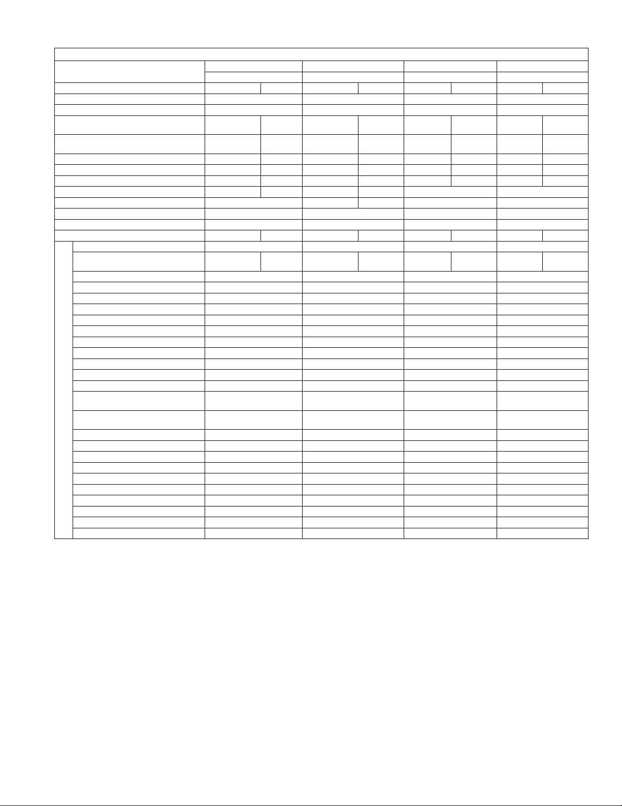
HEAT PUMPS
Model (Indoor/Outdoor)
Function Cooling Heating Cooling Heating Cooling Heating Cooling Heating
Rated Voltage 208/230 208/230 208/230 208/230
Frequency (Hz) 60Hz 60Hz 60Hz 6 0Hz
Total Capacity (Btu/h) (High/Standard/Low)
Total Capacity (W) (High/Standard/Low)
Rated Power Input (W) 882 799 1224 1065 1621 2123 2200 3118
Nominal Input Current (A) 4.01 3.63 5.56 4.84 7.37 9.65 10.00 14.17
SEER/HSPF 16.00 8.5 16.00 8.5 16.00 8 16 9.5
Air Flow Volume (CFM) (H/M/L) 330/300/260/210 330 340/300/260/210 341 470/400/330/270 590/440/300/200
Air Flow Volume (m
Dehumidifying Volume (cu.ft./h) 0.028 0.049 0.064 0.075
Dehumidifying Volume (l/h) 0.80 1.40 1.80 2.13
EER / C.O.P 10.2 3.32 9.8 3.3 11.1 2.65 10 2.5
Model of Indoor Unit DHMF09NWM42Q1 DHMF12NWM42Q1 DHMF18NWM42Q1 DHMF24NWM42Q1
Fan Motor Speed (r/min) (SH/H/M/L)
Output of Fan Motor (w) 15 15 20 36
Fan Motor Capacitor (uF) 1.2 1.2 1.5 2.5
Fan Motor RLA(A) 0.19 0.19 0.32 0.45
Fan Type-Piece Cross-flow - 1 Cross-flow - 1 Cross-flow - 1 Cross-flow - 1
Diameter-Length (inch) 3.6 × 23.4 3.6 × 23.4 3.9 × 25.6 3.9 × 30.1
Diameter-Length (mm) 92 × 594 92 × 595 98 × 650 98 × 765
Evaporator Aluminum Fin-copper Tube Aluminum Fin-copper Tube Aluminum Fin-copper Tube Aluminum Fin-copper Tube
Pipe Diameter (inch) Φ 0.276 Φ 0.276 Φ 0.276 Φ 0.276
Pipe Diameter (mm) φ7 φ7 φ7 φ7
Row-Fin Gap (inch) 2 - 0.055 2 - 0.055 2 - 0.055 2 - 0.059
Row-Fin Gap (mm) 2-1.4 2-1.4 2-1.4 2-1.5
Coil length (L) x height
(H) x coil width (W) (inch)
Indoor Unit
Coil length (L) x height
(H) x coil width (W) (mm)
Output of Swing Motor (W) 1.5 1.5 2 3
Fuse (A) 3.15 3.15 3.15 3.15
Sound Pressure Level dB (A) (SH/H/M/L) 43 / 38 / 32 / 26 44 / 39 / 33 / 28 48 / 43 / 38 / 34 49 / 43 / 39 / 34
Sound Power Level dB (A)(SH/H/M/L) 53 / 48 / 42 / 36 54 / 49 / 43 / 38 58 / 53 / 48 / 43 59 / 53 / 49 / 44
Dimension (W/D/H) (inch) 30.3 × 7.9 × 11.1 30.3 × 7.9 × 11.1 34.1 × 8.5 × 12.0 39.7 × 8.7 × 12.4
Dimension (W/D/H) (mm) 770 × 201 × 283 770 × 201 × 283 865 × 215 × 305 1008 × 221× 315
Dimension of Package (L/W/H) (inch) 33.3 ×10.9 × 13.9 33.3 × 10.9 × 13.9 37.3 × 12.2 × 15.1 42.2 × 12.3 × 15.6
Dimension of Package (L/W/H) (mm) 847 × 276 × 352 847 × 276 × 352 948 × 310 × 383 1073 × 313 × 395
Net Weight /Gross Weight (lbs) 19 / 25 20 / 27 27 / 35 33.0 / 44.0
Net Weight /Gross Weight (kg) 8.6 / 11.5 9.0 / 12.0 12.0 / 16.0 15 / 20
Continued on next page.
3
/h) (H/M/L) 560/510/440/370 580/520/440/370 580 800/680/560/460 1000/750/520/350
DHMF09NWM42Q1 DHMF12NWM42Q1 DHMF18NWM42Q1 DHMF24NWM42Q1
DHMF09CSM42Q1 DHMF12CSM42Q1 DHMF18CSM42Q1 DHMF24CSM42Q1
11500/9000/
3800
3370/2637/
1114
1300/1100/
900/700
24.0 × 11.6 × 0.9 24.0 × 11.6 × 0.9 25.9 × 12.0 × 1.0 30.1 × 13.5 × 1.0
610 × 24 × 294 610 × 24 × 294 657 × 25.4 × 304.8 765 × 25.4 × 342.9
11500/9000/
3300
3370/2637/
967
1300/1150/
980/820
12500/12000/
3300
3663/3516/
967
1350/1150/
950/750
12500/12000/
3400
3663/3516/
996
1350/1190/
1020/850
21000/18000/
4500
6155/5276/
1319
1400/1150/
1000/850
23000/19200/
4000
6741/5276/
1172
1450/1250/
1100/950
24000/22000/
6400
7032/6446/
1875
1400/1180/
1000/850
26600/26600/
7796/6446/
1450/1380/
1200/1150
4100
1202
Johnson Controls Unitary Products 5
Page 6
923178-UTG-B-0114
HEAT PUMPS (Continued)
Model of Outdoor Unit DHMF09CSM42Q1 DHMF12CSM42Q1 DHMF18CSM42Q1 DHMF24CSM42Q1
Compressor Manufacturer/trademark GREE GREE MITSUBISHI SANYO
Compressor Type Inverter Rotary Inverter Rotary Inverter Rotary Inverter Rotary
L.R.A. (A) 16.50 16.50 27 41
Compressor RLA(A) 6.22 6.22 10.86 11.38
Compressor Power Input (W) 950 950 1245 1630
Throttling Method Capillary Capillary Capillary EXV
Working Temp Range (
Working Temp Range (°C) -15 ~ 46 -10 ~ 24 -15 ~ 46 -10 ~ 24 -15 ~ 46 -10 ~ 24 -15 ~ 46 -10 ~ 24
Condenser Aluminum Fin-copper Tube Aluminum Fin-copper Tube Aluminum Fin-copper Tube Aluminum Fin-copper Tube
Pipe Diameter (inch) Φ 0.276 Φ 0.276 Φ 0.276 Φ 0.276
Pipe Diameter (mm) φ7 φ7 φ7 φ7
Rows-Fin Gap (inch) 1 - 0.055 2 - 0.055 2 - 0.055 2 - 0.055
Rows-Fin Gap (mm) 1-1.4 2-1.4 2-1.4 2-1.4
Coil length (l) x height (H) x
coil width (L) (inch)
Coil length (l) x height (H) x
coil width (L) (mm)
Fan Motor Speed (rpm) 880±20 880±20 690 690
Output of Fan Motor (W) 21 21 60 60
Fan Motor RLA(A) 0.25 0.25 0.62 0.62
Fan Motor Capacito r ( uF) 2 2 3 3.5
Fuse (A) 15A 15A 25A 25A
Air Flow Volume of Outdoor Unit (CFM) 944 944 1887 1887
Air Flow Volume of Outdoor Unit (m
Fan Type-Piece Axial-flow-1 Axial-flow-1 Axial-flow-1 Axial-flow-1
Fan Diameter (inch) 14.6 14.6 20.5 20.5
Outdoor Unit
Fan Diameter (mm) 370 370 520 520
Defrosting Method Automatic Defrosting Automatic Defrosting Automatic Defrosting Automatic Defrosting
Climate Type T1 T1 T1 T1
Permissible Excessive Operating
Pressure for the Discharge Side (PSI)
Permissible Excessive Operating
Pressure for the Discharge Side (MPa)
Permissible Excessive Operating
Pressure for the Suction Side (PSI)
Permissible Excessive Operating
Pressure for the Suction Side (MPa)
Sound Pressure Level dB (A) 49 52 56 56
Sound Power Level dB (A) 59 62 66 56
Dimension (W/D/H) (mm) 28.0 × 12.5 × 21.7 28.0 × 12.5 × 21.7 37.9 × 15.6 × 27.6 37.9 × 15.6 × 27.6
Dimension (W/D/H) (mm) 711 × 318 × 551 711 × 318 × 551 963 × 396 × 701 963 × 396 × 701
Dimension of Package (L/W/H) (inch) 30.4 × 13.7 × 23.3 30.4 × 13.7 × 23.3 40.4 × 17.9 × 28.9 40.4 × 17.9 × 28.9
Dimension of Package (L/W/H) (mm) 771 × 348 × 592 771 × 348 × 592 1026 × 455 × 735 1026 × 455 × 735
Net Weight /Gross Weight (lbs) 64 / 73 68 / 77 106 / 117 115 / 126
Net Weight /Gross Weight (kg) 29 / 33 31 / 35 48 / 53 52 / 57
Refrigerant Charge (oz) 26.1 35.3 44.1 54.7
Refrigerant Charge (kg) 0.74 1.00 1.25 1.55
MCA 10.0 10.0 15.0 16.0
MOP 15.0 15.0 25.0 25.0
Length (ft) 25 25 25 25
Length (m) 7.5 7.5 7.5 7.5
Gas additional charge (oz/ft) 0.2 0.2 0.2 0.2
Gas additional charge (g/m) 20 20 20 20
Outer Diameter Liquid Pipe (inch) Φ 1/4 Φ 1/ 4 Φ 1/4 Φ 1/4
Outer Diameter Liquid Pipe (mm) φ6 φ6 φ6 φ6
Outer Diameter Gas Pipe (inch) Φ 3/8 Φ 3/8 Φ 1/2 Φ 1/2
Outer Diameter Gas Pipe (mm) φ9.52 φ9.52 φ12 φ12
Connection Pipe
Max Height Distance (ft) 32.8 32.8 32.8 32.8
Max Height Distance (m) 9.9 9.9 9.9 9.9
Max Length Distance (ft) 49.2 49.2 82 82
Max Length Distance (m) 14.9 14.9 24.9 24.9
o
F) 5 ~ 115 14 ~ 75 5 ~ 115 14 ~ 75 5 ~ 115 14 ~ 75 5 ~ 115 14 ~ 75
25.5 × 20.8 × 0.8 25.5 × 20.8 × 1.5 33.0 × 26.0 × 1.5 33.6 × 26.0 × 1.5
647 × 19.05 × 528 647 × 38.1 × 528 837 × 38.1 × 660 853 × 38.1 × 660
3
/h) 1600 1600 3200 3200
624 624 624 624
4.3 4.3 4.3 4.3
363 363 363 363
2.5 2.5 2.5 2.5
6 Johnson Controls Unitary Products
Page 7
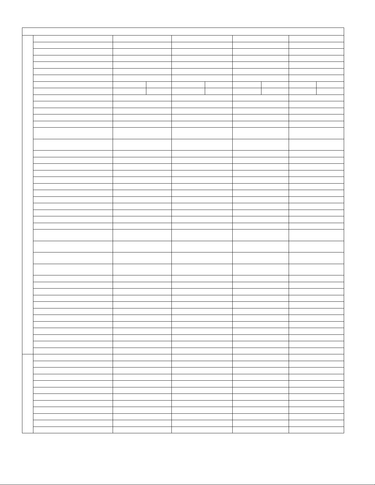
PRODUCT OPERATION CHARACTERISTIC CURVES
Cooling Heating
0
1
2
3
4
5
6
7
8
9
10
0 20 40 60 80 100 120
Condition
F°6.08 BD:roodnI
WB66.2
°F
Indoor air flow: Super High
Pipe length:24.6ft
0
1
2
3
4
5
6
7
8
0 20 40 60 80 100 120
Condition
Indoor:DB 68°F
Indoor air flow: Super High
Pipe length:24.6ft
Current(A)
Current(A)
09K 12K
Compressor Frequency(Hz)
Compressor Frequency(Hz)
18K
Cooling
Heating
0
1
2
3
4
5
6
7
8
9
10
020406080
100 120
Condition
F°6.08 BD:roodnI
WB66.2
°F
Indoor air flow: Super High
Pipe length:24.6ft
Compressor Frequency(Hz)
0
2
4
6
8
10
12
0 20 40 60 80 100 120
Condition
Indoor:DB 68°F
Indoor air flow: Super High
Pipe length:24.6ft
Compressor Frequency(Hz)
Current(A)
Current(A)
923178-UTG-B-0114
Johnson Controls Unitary Products 7
Page 8
923178-UTG-B-0114
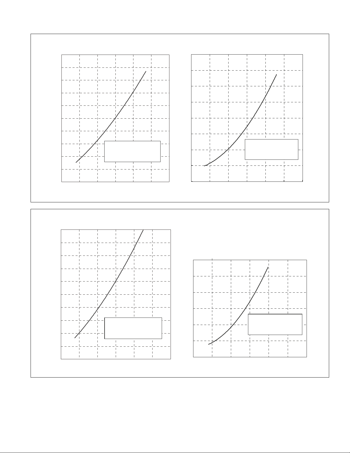
Cooling
Heating
24K
0
2
4
6
8
10
12
14
0204060
0
2
4
6
8
10
12
14
0 20 40 60 80 100 120
Conditio
n
F°6.08 BD:roodnI
WB66.2
°F
Indoor air flow: Super High
Pipe length:24.6ft
Condition
Indoor:DB 68°F
Indoor air flow: Super High
Pipe length:24.6ft
Compressor Frequency(Hz)
Compressor Frequency(Hz)
09K 12K
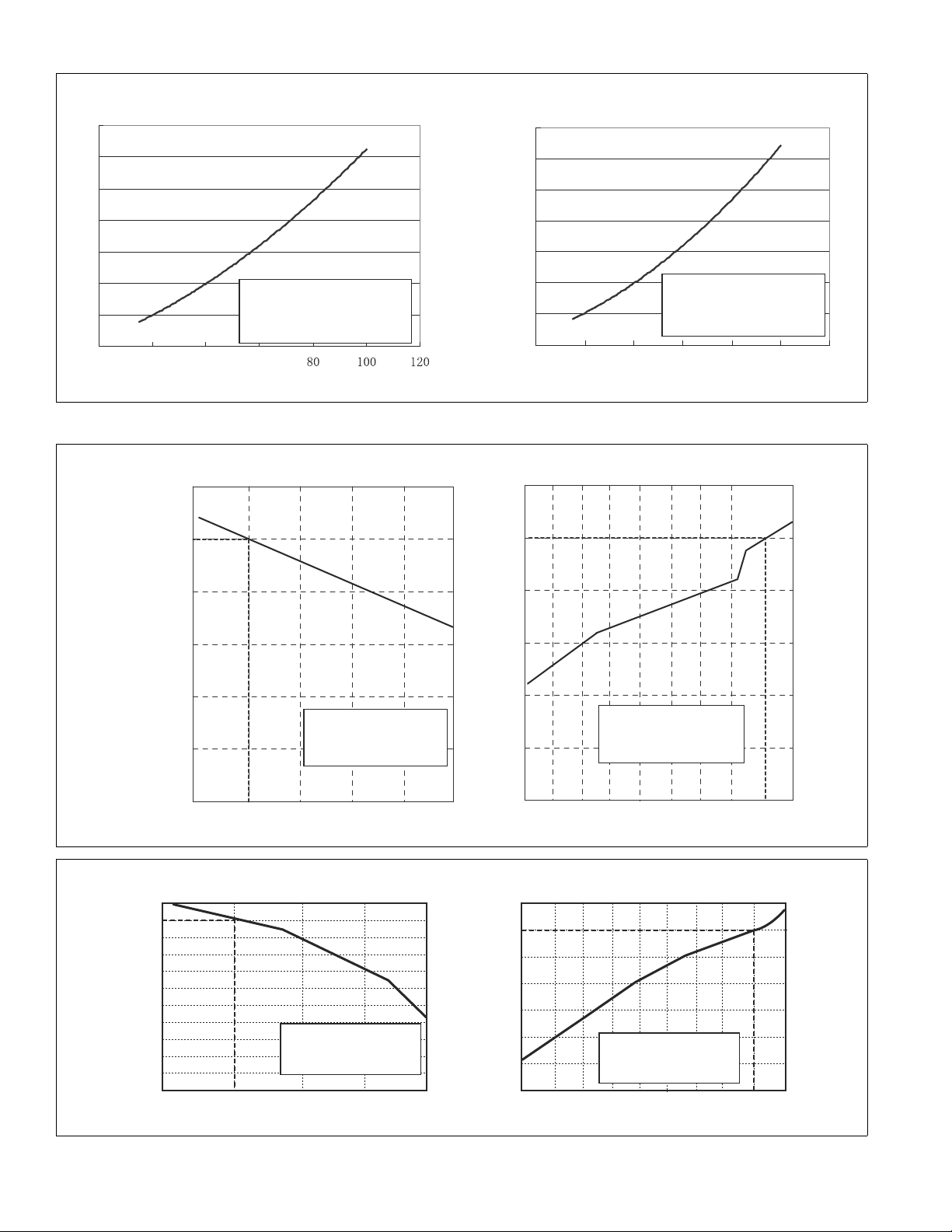
Heating
Cooling
50
60
70
80
90
100
110
Capacity ratio(%)
Condition
Indoor air flow: Super High
Pipe length:
24.6ft
Outdoor temp. (°F)
0
20
40
60
80
100
120
510152025 3035404550
Capacity ratio(%)
Condition
Indoor air flow: Super High
Pipe length:
24.6ft
Outdoor temp. (°F)
Indoor:DB 68°F
Indoor:DB 80.6°F
WB66.2
°F
90 95 100 105 110 115
18K 24K
<Cooling> <Heating>
95 100 105 110
51015202530354045 50
100
105
95
90
85
80
75
70
65
60
55
50
Outdoor temp. (˚F)
110
100
90
80
70
60
50
40
Outdoor temp. (˚F)
Capacity ratio (%)
Conditions
Indoor:
Indoor air flow : High
Pipe length :
24.6ft
90
Capacity ratio (%)
DB 80.6°F
WB66.2
°F
Condition
Indoor:DB 68°F
Indoor air flow: Super High
Pipe length:24.6ft
PRODUCT CAPACITY VARIATION RATIO
8 Johnson Controls Unitary Products
Page 9
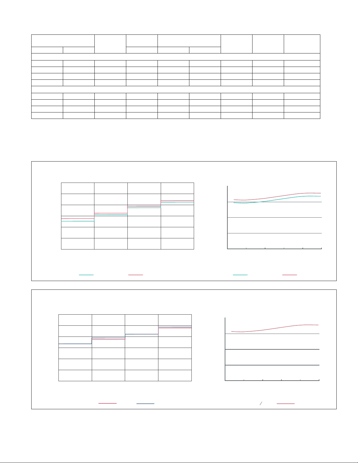
OPERATION DATA
Indoor side noise when blowing
Outdoor side noise
60
60
60 80 100
50
50
40
40
40
30
30
20
20
20
10
0
0
Indoor Fan Motor Rotating Speed
Noice/dB(A)
Noice/dB(A)
low
Middle
High Super High
Compressor frequency/Hz
09K 12K 09K 12K
09K 12K
Indoor side noise when blowing
Outdoor side noise
18K
24K
60
60
60 80 100
50
50
40
40
40
30
30
20
20
20
10
0
0
Indoor Fan Motor Rotating Speed
Noice/dB(A)
low
Middle
High Super High
Compressor frequency/Hz
18 24K
18K 24K
Noice/dB(A)
Temperature Condition (°F)
Indoor Outdoor P (MPa) T1 (°F) T2 (°F)
80/66.9 95/75 09K 0.9 to 1.1 53.6 to 57.2 158 to 104 Super High High 73
80/66.9 95/75 12K 0.9 to 1.1 53.6 to 57.2 158 to 104 Super High High 71
80/66.9 95/75 18K 0.9 to 1.1 53.6 to 57.2 176 to 104 Super High High 75
80/66.9 95/75 24K 0.9 to 1.1 53.6 to 57.2 176 to 104 Super High High 89
70/60 46.9/43 09K 2.5 to 2.7 158 to 95 35.6 to 39.2 Super High High 76
70/60 46.9/43 12K 2.5 to 2.7 158 to 95 35.6 to 39.2 Super High High 76
70/60 46.9/43 18K 2.2 to 2.4 158 to 104 33.8 to 41.0 Super High High 90
70/60 46.9/43 24K 2.2 to 2.4 158 to 104 33.8 to 41.0 Super High High 87
Notes:
Measure surface temperature of heat exchanger pipe around center of heat exchanger path U bent. (Thermistor thermometer).
Connecting piping condition: 24.6 ft.
P: pressure of air pipe connected to the indoor and outdoor units (g as valve side),
T1: Inlet and outlet temperature for evaporator,
T2: Inlet and outlet temperature for condenser.
Model name
Standard
Pressure
Heat Exchanger
Pipe Temperature
COOLING
HEATING
Indoor Fan
Mode
Outdoor Fan
Mode
SOUND DATA
923178-UTG-B-0114
Compressor
Frequency (Hz)
Johnson Controls Unitary Products 9
Page 10
923178-UTG-B-0114
5.0 21.6
3.7
09K 12K
7.221.3
5.5
18K
7.6
27.05.1
24K
A
C
B
B
A
C
G
D
E
F
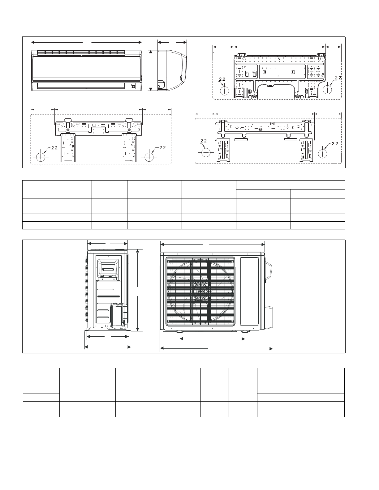
PRODUCT CONSTUCTION VIEW & DIMENSIONS
Indoor Unit Dimensions
Model Size A B C
09K
12K 27 lbs (12 kg) 27 lbs (12 kg)
18K 34.1 (866) 8.5 (216) 12.0 (305) 35 lbs (16 kg) 35 lbs (16 kg)
24K 39.7 (1008) 8.7 (221) 12.4 (315) 44 lbs (20 kg) 44 lbs (20 kg)
30.3 (770) 7.9 (201) 11.1 (282)
Unit Gross Weight
Air Conditioner Heat Pump
25 lbs (11.5 kg) 25 lbs (11.5 kg)
Outdoor Unit Dimensions
Model Size A B C D E F G
09K
12K 77 lbs (35 kg) 77 lbs (35 kg)
18K
24K 123 lbs (56 kg) 126 lbs (57 kg)
28.0 (711 ) 12.5 (318) 21.7 (551) 11.8 (300) 10.8 (274) 25.9 (658) 18.5 (470)
37.9 (963) 15.6 (396 ) 27.6 (701) 14.4 (366) 13.4 (340) 35.0 (889) 22.0 (559)
Unit Gross Weight
Air Conditioner Heat Pump
73 lbs (33 kg) 73 lbs (33 kg)
115 lbs (52 kg) 117 lbs (53 kg)
10 Johnson Controls Unitary Products
Page 11
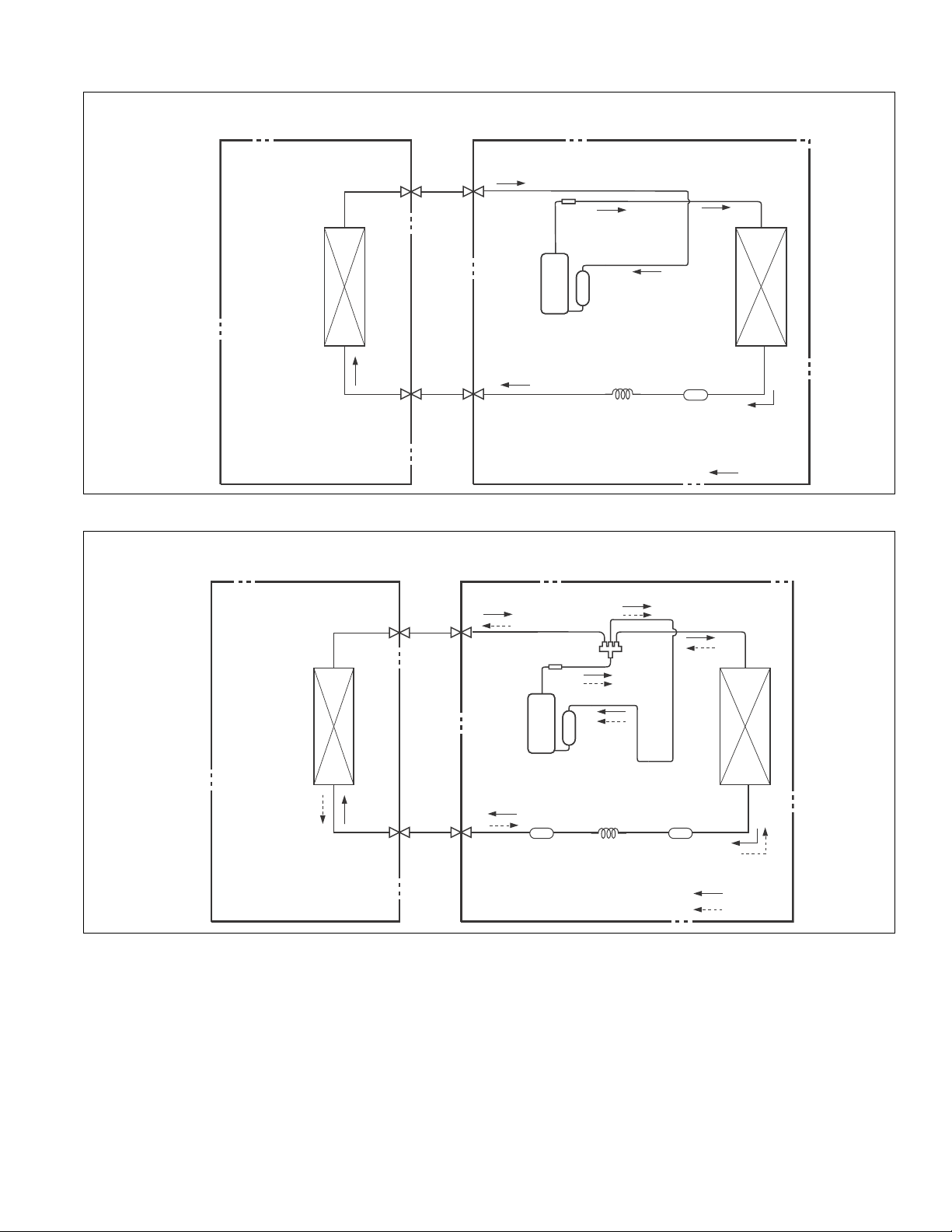
REFRIGERANT SYSTEM DIAGRAM
09K/12K/18K Cooling Only Models
09K/12K/18K Heat Pumps
INDOOR UNIT OUTDOOR UNIT
923178-UTG-B-0114
GAS SIDE
See Page 12 for notes.
3-WAY VALVE
HEAT
EXCHANGE
(EVAPORATOR)
LIQUID SIDE
2-WAY VALVE
Muffler
Discharge
Suction
Accumlator
COMPRESSOR
Capillary Strainer
INDOOR UNIT OUTDOOR UNIT
GAS SIDE
3-WAY VALVE
Muffler
HEAT
EXCHANGE
(CONDENSER)
COOLING
4-Way valve
HEAT
EXCHANGE
(EVAPORATOR)
See Page 12 for notes.
LIQUID SIDE
2-WAY VALVE
Discharge
Suction
Accumlator
COMPRESSOR
HEAT
EXCHANGE
(CONDENSER)
CapillaryStrainer Strainer
COOLING
HEATING
Johnson Controls Unitary Products 11
Page 12

923178-UTG-B-0114
HEAT
EXCHANGE
(EVAPORATOR)
HEAT
EXCHANGE
(CONDENSER)
COMPRESSOR
GAS SIDE
3-WAY VALVE
LIQUID SIDE
2-WAY VALVE
COOLING
Accumlator
Discharge
Suction
Muffler
Strainer
Electron expansion valve
24K Cooling Only Models
HEAT
EXCHANGE
(EVAPORATOR)
HEAT
EXCHANGE
(CONDENSER)
COMPRESSOR
GAS SIDE
3-WAY VALVE
LIQUID SIDE
2-WAY VALVE
COOLING
HEATING
Accumlator
Discharge
Suction
Muffler
4-Way valve
Electron expansion valve
Strainer Strainer
24K Heat Pumps
See below for notes.
INDOOR UNIT OUTDOOR UNIT
NOTES:
Refrigerant pipe diameter
Liquid: 1/4” (0.24 inch)
Gas: 3/8” (0.37 inch)(09K 12K)
Gas: 1/2” (0.47 inch)(18K 24K)
INDOOR UNIT OUTDOOR UNIT
12 Johnson Controls Unitary Products
Page 13

923178-UTG-B-0114
WIRING DIAGRAM
Electrical Data
Symbol Color Symbol Symbol Color Symbol Symbol Part Name
INDOOR UNIT
BU BlUE BN BROWN PROTECTIVE EARTH
YE YELLOW GN GREEN / /
RD RED BK BLACK / /
YEGNYELLOW GREEN////
OUTDOOR UNIT
Symbol Part Name Symbol Color Symbol Symbol Color Symbol
C1 CBB61 BN BROWN WH WHITE
C2 CBB65 BU BLUE YE YELLOW
SAT OVERLOAD BK BLACK RD RED
COMP COMPRESSOR OG ORANGE YEGN YELLOW GREEN
PROTECTIVE EARTH WH WHITE / /
Electrical Wiring
09K & 12K Outdoor Air Conditioners
Johnson Controls Unitary Products 13
Page 14

923178-UTG-B-0114
09K & 12K Indoor Air Conditioners
18K & 24K Outdoor Air Conditioners
14 Johnson Controls Unitary Products
Page 15

923178-UTG-B-0114
18K & 24K Indoor Air Conditioners
09K & 12K Outdoor Heat Pumps
Johnson Controls Unitary Products 15
Page 16

923178-UTG-B-0114
09K & 12K Indoor Heat Pumps
18K & 24K Outdoor Heat Pumps
16 Johnson Controls Unitary Products
Page 17

18K
24K
Start cooling
Stop cooling
sorserpmoC
Original working state
Run
Stop
Outdoor fan
Indoor fan
T
preset
T
preset
+3.6
T
amb.
Preset fan speed
6 minutes
6 minutes
3 minutes
ºF
923178-UTG-B-0114
18K & 24K Indoor Heat Pumps
DESCRIPTION OF EACH CONTROL
OPERATION
Temperature & Current Parameters
• Indoor preset temperature (T
• Indoor ambient temperature (T
• Evaporator coil temperature (T
• Condenser coil temperature (T
• Defrost compensation temperature (T
• Outdoor ambient temperature (T
• Measured temperature of outdoor condensing coil under
cooling mode and measured temperature of indoor evaporator coil under heating mode (T
• Indoor ambient temperature (T
Basic Functions
Once energized, the compressor should never be restarted
within less than 3 minutes. In a situation where memory function is available when energized for the first time, if the compressor is at stop before de-energized, it will re-start without a
3-minute lag. If it has been in operation before de- energized,
the compressor will start with a 3-minute lag. Once started, the
compressor will not be stopped within 6 minutes regardless of
changes in room temperature.
Cooling Mode
1. Cooling Mode Operation
• When T
amb
T
fan, outdoor fan and the compressor will operate simultaneously. The indoor fan will run at preset speed.
• When T
amb
T
outdoor fan will stop with a time lag of 60 seconds, and the
indoor fan will run at preset speed.
• When T
preset
remain at its previous state.
In cooling mode, the four-way valve will be de-energized and
temperature can be set within a range from 61 to 86°F. If the
compressor stops running, the indoor fan and the swing device
will operate at original state.
Johnson Controls Unitary Products 17
, cooling mode is activated. The indoor
preset
- 3.6,°F the compressor will stop, the
preset
- 3.6°F < T
amb
)
preset
.)
amb
)
evap
outdoor pipe
outdoor amb
tube
indoor amb)
)
compensation
).
. < T
+ 1.8°F, the unit will
preset
)
)
2. Protection – Cooling Mode
• Antifreeze protection - In cooling and dehumidification
mode, antifreeze protection is activated 6 minutes after the
compressor has started if one of followings occur:
T
35.6 °F, the compressor will operate at reduced
evap
frequency.
T
30.2 °F is detected for a duration of 3 minutes,
evap
the compressor will stop and after 60 seconds, the outdoor fan will stop. In cooling mode, the indoor fan and the
swing motor will remain at the original state.
T
42.8 °F and the compressor has remained in
evap.
OFF mode for at least 3 minutes, the compressor will
resume its original operation state.
• Total current up and freq uency down protection if the followings occur:
I
16A, the compressor frequency will start to
total
increase
I
17A, the compressor frequency will not increase
total
18A, the compressor will run at reduced frequency
I
total
20A, the compressor will immediately stop and the
I
total
outdoor fan will stop after 60 seconds
Page 18

923178-UTG-B-0114
Dehumidification Mode
1. Dehumidification Mode Operation
• When T
amb
> T
+ 1.8 °F, cooling and dehumidification
preset
mode will be activated. The compressor and th e outdoor
fan will operate while the indoor fan runs at low speed.
• When T
preset
- 3.6 °F T
amb
T
+ 1.8°F, the compres-
preset
sor remains at its original operation state.
• When T
amb
. < T
- 3.6°F, the compressor will stop, the
preset
outdoor fan will stop after 60 seconds and the indoor fan
will operate at low speed.
2. Protection – Dehumidification Mode
Protection is the same as that under cooling mode section.
Heating Mode
1. Heating Mode Operation
• When T
amb
. T
+ 3.6°F, heating mode is activated.
preset
The four-way valve, the compressor and the outdoor fan
will operate simultaneously. The indoor fan will run at preset speed defined under “cold air prevention”.
• When T
amb
. T
+ 9°F, the compressor will stop, the
preset
outdoor fan will stop after 60 seconds, and the indoor fan
will continue to run at low speed for 60 seconds more.
• When T
preset
+ 3.6°F<T
amb
.<T
+ 9°F, the unit will
preset
maintain its original operating status.
In heating mode, the four-way valve is energized an d temperature can be set within a range of 61 - 86°F. The heating symbol
and preset temperature are displayed on the indoor unit display.
2. Defrost Mode Operation
When the system has been running continuously in heating
mode for more than 45 minutes, or an accumulated heating
time of more than 90 minutes, and one of the following conditions are present, the unit will enter defrost mode after 3 minutes.
•T
outdoor amb.
• 28.4°F≤T
• 23°F≤T
• 14°F≤T
•T
outdoor amb.
outdoor amb.
door amb
outdoor amb.
≥ 41°F, T
outdoor amb.
-5.4°F);
<14°F, T
outdoor pipe
<28.4°F, T
<23°F, T
outdoor pipe-Tcompensation
≤28.4°F;
outdoor pipe
outdoor pipe
≤17.6°F;
- T
compensation
≤ (T
outdoor amb.
≤ (T
out-
5.4°F)
NOTE:
After defrost mode is energized for the first time, T
0°F. After the first time, T
densing coil temperature T
•T
outdoor pipe
•T
outdoor pipe
>35.6°F, T
≤35.6°F, T
compensation
outdoor pipe
compensation
compensation
is determined by the con of the last defrost cycle.
= 0°F;
= 5.4°F
compensation
When in defrost mode the following will occur in the order
described:
a. The indoor fan and compressor stop running
b. The outdoor fan will stop running after 60 seconds.
c. 30seconds later, the four-way valve will close.
d. After 30 seconds, the compressor’s frequency is
increased to defrost frequency.
e. When the compressor has operated in defrost mode for
10 minutes, or T
outdoor pipe
≥ 50°F, the compressor will
adjust to 46Hz.
f. After 30 seconds, the compressor will stop.
g. After another 30 seconds, the four-way valve will open.
h. After 60 seconds, the compressor and the outdoor unit fan
will start running. The indoor fan will run under preset cold
air prevention conditions. H1 will be displayed on the
indoor unit display. Defrost frequency is 70Hz.
3. Protection – Heating Mode
• Cold air prevention (Hot Heat Pump) - In heating mode,
after the compressor is energized the indoor fan is delayed
under these conditions to prevent discharging cold air:
When T
T
tube
indoor amb.
≤104°F, the indoor fan will not run. The indoor fan
<75°F if:
will start running at low speed after 2 minutes.
Within 2 minutes, if T
>104°F, the indoor fan will start
tube
running at low speed.
After 1minute of operation at low speed, the indoor fan
will run at preset speed.
Within 1-minute of low speed operation or 2-minute
non-operation, if T
>108°F, the fan will run at present
tube
speed.
When T
T
tube
indoor amb.
≤108°F, the indoor fan will run at low speed. After
≥75°F if:
one minute of operation, the indoor fan wil l run at preset speed.
Within one-minute of low speed operation, if
T
>104°F, the indoor fan will run at preset speed.
tube
Total current up and frequency down protection occurs:
When I
When I
≤16A, compressor frequency can increase
total
≥17A, compressor frequency is not allowed
total
to increase
When I
≥18A, the compressor runs at reduced fre-
total
quency
When I
≥20A, the compressor stops running and the
total
outdoor fan stops running after 60 seconds.
Fan Mode
In this mode, the indoor fan will run at preset speed. The compressor, the outdoor fan and the four-way valve will not be running.
1. In fan mode, temperature can be set within a range of 61 -
-
86°F.
AUTO Mode
1. AUTO Mode Operation
=
In AUTO mode, the default cooling setpoint temperature T
is 77°F and the default heating setpoint temperature T
68°F. Once activated, the following will occur under these con-
ditions:
• When T
• When 71.6°F< T
fan icon is displayed on the indoor unit display.
• When T
• When T
mode. The preset temperature is 77°F;
• When T
the outdoor fan stops running after 1 minute, and the indoor
fan continues to run at a preset speed.
• When T
tinues to run normally.
• When T
•T
amb.≥Tpreset
door fan stops running after 1 minute, and the indoor fan
continues to run for about 30 seconds before it stops.
≤71.6°F, heating mode is activated.
amb.
<78.8°F, fan mode is activated and the
amb.
≥78.8°F, cooling mode is activated.
amb.
amb.≥Tpreset
amb. ≤Tpreset
preset
amb.≤Tpreset
+1.8°F, the system runs in cooling
-1.8°F, the compressor stops running,
-1.8°F< T
amb.
< T
+1.8°F, the system con-
preset
+3.6°F, heating mode is activated.
+9°F, the compressor stops running, the out-
preset
preset
is
18 Johnson Controls Unitary Products
Page 19

923178-UTG-B-0114
• When T
preset
+3.6°F< T
amb.
< T
+41°F, the system con-
preset
tinues to run normally
• When 71.6°F<T
<78.8°F, the system continues to run
amb.
normally.
2. Protection – Auto Mode
• When the system is running in cooling mode, the protections described in “Protection - Cooling Mode” apply.
• When the system is running in heating mode, the protections described in “Protection – Heating Mode” apply.
• When the ambient temperature changes, operation mode
will switch back and forth. Once the compressor is ene rgized, it will keep running for a minimum of 6 minutes.
COMMON PROTECTION FUNCTIONS AND
FAULT DISPLAY UNDER COOL, HEAT, DRY
AND AUTO MODES
1. Overload Protection
• Cooling Overload
When T
When T
allowed to increase.
When T
quency.
When T
the indoor fan will continue to run at preset speed.
Heating Overload
When T
When T
allowed to increase.
When T
quency.
≤ 126⁰F, the system operates normally.
tube
≥ 131⁰F, compressor frequency is not
tube
≥ 136⁰F, compressor will run at reduced fre-
tube
≥ 144⁰F, compressor is de-energized and
tube
≤ 126⁰F, the system operates normally.
tube
≥ 131⁰F, compressor frequency is not
tube
≥ 136⁰F, compressor will run at reduced fre-
tube
When T
≥ 144⁰F, compressor is de-energized and
tube
the indoor fan will continue to run for about 30 seconds
and stops.
2. High Discharge Temperature Compressor Protection
• When compressor discharge temperature is ≥ 208 ⁰F, compressor frequency is not allowed to increase.
• When compressor discharge temperature is ≥ 217 ⁰F, compressor will run at reduced frequency.
• When compressor discharge temperature is ≥ 230 ⁰F, t he
compressor will stop.
• When compressor discharge temperature is ≤ 194 ⁰F and
the compressor has been idle for at least 3 minutes, it will
resume its operation.
3. Communication Fault
If the system fails to receive communication signals for more
than 3 minutes, its operation will stop.
4. Module Protection
• Under module protection mode, the compressor will stop.
• If the compressor remains idle for at least 3 minutes, it will
resume its operation.
• If module protection occurs six consecutive times, the compressor will not be allowed to start again.
5. Overload Protection
• If the overload temperature is over 239 ⁰F, the compressor
will stop and the outdoor fan will stop after 30 seconds.
• If the overload temperature drops below 203 ⁰F, t h e c om pressor overload protection is reset.
• If voltage on the DC bus is below 150V or over 420V, the
compressor will stop and the outdoor fan will stop after 30
seconds.
• When voltage on the DC bus returns to its normal value
and the compressor has been idle for at least 3 minutes,
the compressor will resume its operation.
6. Temperature Sensors Faults.
Designation of Sensors Faults
Indoor ambient temperature The sensor is detected to be open-circuited or short-circuited for a continuous 30 seconds.
Indoor tube temperature The sensor is detected to be open-circuited or short-circuited for a continuous 30 seconds.
Outdoor ambient temperature The sensor is detected to be open-circuited or short-circuited for a continuous 30 seconds.
Outdoor tube temperature
Exhaust
Overload
The sensor is detected to be open-circuited or short-circuited for a continuous 30 seconds and no detection is
performed within 10 minutes after defrost begins.
After the compressor has operated for 3minutes, the sensor is detected to be open-circuited or short-circuited for a
continuous 30 seconds.
After the compressor has operated for 3minutes, the sensor is detected to be open-circuited or short-circuited for a
continuous 30 seconds.
Johnson Controls Unitary Products 19
Page 20

923178-UTG-B-0114
RESISTANCE TABLES
Resistance Table of Ambient Temperature Sensor for Indoor and Outdoor Units (15K)
Temp. (°F) Resistance (k) Temp. (°F) Resistance (k) Temp. (°F) Resistance (k) Temp. (°F) Resistance (k)
-2.2 138.1 68 18.75 138.2 3.848 208.4 1.071
-0.4 128.6 69.8 17.93 140 3.711 210.2 1.039
1.4 121.6 71.6 17.14 141.8 3.579 212 1.009
3.2 115 73.4 16.3 9 143.6 3.454 213.8 0.98
5 108.7 75.2 15.68 145.4 3.333 215.6 0.952
6.8 102.9 77 15 147.2 3.217 217.4 0.925
8.6 97.4 78.8 14.36 149 3.105 219.2 0.898
10.4 92.22 80.6 13.74 150.8 2.998 221 0.873
12.2 87.35 82.4 13.16 152.6 2.896 222.8 0.848
14 82.75 84.2 12.6 154.4 2.797 224.6 0.825
15.8 78.43 86 12.07 156.2 2.702 226.4 0.802
17.6 74.35 87.8 11.57 158 2.611 228.2 0.779
19.4 70.5 89.6 11.09 159.8 2.523 230 0.758
21.2 66.88 91.4 10.63 161.6 2.439 231.8 0.737
23 63.46 93.2 10.2 163.4 2.358 233.6 0.717
24.8 60.23 95 9.779 165.2 2.28 235.4 0.697
26.6 57.18 96.8 9.382 167 2.206 237.2 0.678
28.4 54.31 98.6 9.003 168.8 2.133 239 0.66
30.2 51.59 100.4 8.642 170.6 2.064 240.8 0.642
32 49.02 102.2 8.297 172.4 1.997 242.6 0.625
33.8 46.6 104 7.967 174.2 1.933 244.4 0.608
35.6 44.31 105.8 7.653 176 1.871 246.2 0.592
37.4 42.14 107.6 7.352 177.8 1.811 248 0.577
39.2 40.09 109.4 7.065 179.6 1.754 249.8 0.561
41 38.15 111.2 6.791 181.4 1.699 251.6 0.547
42.8 36.32 113 6.529 183.2 1.645 253.4 0.532
44.6 34.58 114.8 6.278 185 1.594 255.2 0.519
46.4 32.94 116.6 6.038 186.8 1.544 257 0.505
48.2 31.38 118.4 5.809 188.6 1.497 258.8 0.492
50 29.9 120.2 5.589 190.4 1.451 260.6 0.48
51.8 28.51 122 5.379 192.2 1.408 262.4 0.467
53.6 27.18 123.8 5.197 194 1.363 264.2 0.456
55.4 25.92 125.6 4.986 195.8 1.322 266 0.444
57.2 24.73 127.4 4.802 197.6 1.282 267.8 0.433
59 23.6 129.2 4.625 199.4 1.244 269.6 0.422
60.8 22.53 131 4.456 201.2 1.207 271.4 0.412
62.6 21.51 132.8 4.294 203 1.171 273.2 0.401
64.4 20.54 134.6 4.139 204.8 1.136 275 0.391
66.2 19.63 136.4 3.99 206.6 1.103 276.8 0.382
20 Johnson Controls Unitary Products
Page 21

923178-UTG-B-0114
Resistance Table of Outdoor and Indoor T u be Temperature Sensors (20K)
Temp. (°F) Resistance (k) Temp. (°F) Resistance (k) Temp. (°F) Resistance (k) Temp. (°F) Resistance (k)
-2.2 181.4 68 25.01 138.2 5.13 208.4 1.427
-0.4 171.4 69.8 23.9 140 4.948 210.2 1.386
1.4 162.1 71.6 22.85 141.8 4.773 212 1.346
3.2 153.3 73.4 21.85 143.6 4.605 213.8 1.307
5 145 75.2 20.9 145.4 4.443 215.6 1.269
6.8 137.2 77 20 147.2 4.289 217.4 1.233
8.6 129.9 78.8 19.14 149 4.14 219.2 1.198
10.4 123 80.6 18.13 150.8 3.998 221 1.164
12.2 116.5 82.4 17.55 152.6 3.861 222.8 1.131
14 110.3 84.2 16.8 154.4 3.729 224.6 1.099
15.8 104.6 86 16.1 156.2 3.603 226.4 1.069
17.6 99.13 87.8 15.43 158 3.481 228.2 1.039
19.4 94 89.6 14.79 159.8 3.364 230 1.01
21.2 89.17 91.4 14.18 161.6 3.252 231.8 0.983
23 84.61 93.2 13.59 163.4 3.144 233.6 0.956
24.8 80.31 95 13.04 165.2 3.04 235.4 0.93
26.6 76.24 96.8 12.51 167 2.94 237.2 0.904
28.4 72.41 98.6 12 168.8 2.844 239 0.88
30.2 68.79 100.4 11.52 170.6 2.752 240.8 0.856
32 65.37 102.2 11.06 172.4 2.663 242.6 0.833
33.8 62.13 104 10.62 174.2 2.577 244.4 0.811
35.6 59.08 105.8 10.2 176 2.495 246.2 0.77
37.4 56.19 107.6 9.803 177.8 2.415 248 0.769
39.2 53.46 109.4 9.42 179.6 2.339 249.8 0.746
41 50.87 111.2 9.054 181.4 2.265 251.6 0.729
42.8 48.42 113 8.705 183.2 2.194 253.4 0.71
44.6 46.11 114.8 8.37 185 2.125 255.2 0.692
46.4 43.92 116.6 8.051 186.8 2.059 257 0.674
48.2 41.84 118.4 7.745 188.6 1.996 258.8 0.658
50 39.87 120.2 7.453 190.4 1.934 260.6 0.64
51.8 38.01 122 7.173 192.2 1.875 262.4 0.623
53.6 36.24 123.8 6.905 194 1.818 264.2 0.607
55.4 34.57 125.6 6.648 195.8 1.736 266 0.592
57.2 32.98 127.4 6.403 197.6 1.71 267.8 0.577
59 31.47 129.2 6.167 199.4 1.658 269.6 0.563
60.8 30.04 131 5.942 201.2 1.609 271.4 0.549
62.6 28.68 132.8 5.726 203 1.561 273.2 0.535
64.4 27.39 134.6 5.519 204.8 1.515 275 0.521
66.2 26.17 136.4 5.32 206.6 1.47 276.8 0.509
Johnson Controls Unitary Products 21
Page 22

923178-UTG-B-0114
Resistance Table of Outdoor Discharge Temperature Sensor (50K)
Temp. (°F) Resistance (k) Temp. (°F) Resistance (k) Temp. (°F) Resistance (k) Temp. (°F) Resistance (k)
-20.2 853.5 50 98 120.2 18.34 190.4 4.754
-18.4 799.8 51.8 93.42 122 17.65 192.2 4.609
-16.6 750 53.6 89.07 123.8 16.99 194 4.469
-14.8 703.8 55.4 84.95 125.6 16.36 195.8 4.334
-13 660.8 57.2 81.05 127.4 15.75 197.6 4.204
-11.2 620.8 59 77.35 129.2 15.17 199.4 4.079
-9.4 580.6 60.8 73.83 131 14.62 201.2 3.958
-7.6 548.9 62.6 70.5 132.8 14.09 203 3.841
-5.8 516.6 64.4 67.34 134.6 13.58 204.8 3.728
-4 486.5 66.2 64.33 136.4 13.09 206.6 3.619
-2.2 458.3 68 61.48 138.2 12.62 208.4 3.514
-0.4 432 69.8 58.77 140 12.17 210.2 3.413
1.4 407.4 71.6 56.19 141.8 11.74 212 3.315
3.2 384.5 73.4 53.74 143.6 11.32 213.8 3.22
5 362.9 75.2 51.41 145.4 10.93 215.6 3.129
6.8 342.8 77 49.19 147.2 10.54 217.4 3.04
8.6 323.9 78.8 47.08 149 10.18 219.2 2.955
10.4 306.2 80.6 45.07 150.8 9.827 221 2.872
12.2 289.6 82.4 43.16 152.6 9.489 222.8 2.792
14 274 84.2 41.34 154.4 9.165 224.6 2.715
15.8 259.3 86 39.61 156.2 8.854 226.4 2.64
17.6 245.6 87.8 37.96 158 8.555 228.2 2.568
19.4 232.6 89.6 36.38 159.8 8.268 230 2.498
21.2 220.5 91.4 34.88 161.6 7.991 231.8 2.431
23 209 93.2 33.45 163.4 7.726 233.6 2.365
24.8 198.3 95 32.09 165.2 7.47 235.4 2.302
26.6 199.1 96.8 30.79 167 7.224 237.2 2.241
28.4 178.5 98.6 29.54 168.8 6.998 239 2.182
30.2 169.5 100.4 28.36 170.6 6.761 240.8 2.124
32 161 102.2 27.23 172.4 6.542 242.6 2.069
33.8 153 104 26.15 174.2 6.331 244.4 2.015
35.6 145.4 105.8 25.11 176 6.129 246.2 1.963
37.4 138.3 107.6 24.13 177.8 5.933 248 1.912
39.2 131.5 109.4 23.19 179.6 5.746 249.8 1.863
41 125.1 111.2 22.29 181.4 5.565 251.6 1.816
42.8 119.1 113 21.43 183.2 5.39 253.4 1.77
44.6 113.4 114.8 20.6 185 5.222 255.2 1.725
46.4 108 116.6 19.81 186.8 5.06 257 1.682
48.2 102.8 118.4 19.06 188.6 4.904 258.8 1.64
22 Johnson Controls Unitary Products
Page 23

REMOVAL PROCEDURE
Axonometric drawing for the
complete unit.
panel
clasps
filter
a. Open the panel.
b. Loosen the clasps
on the filter.
c. Draw out two
pieces of filter.
Display
Remove 2 screws fixing display,
and then remove the filter.
Removal Procedure of Indoor Unit
Be sure to wait for a minimum of 10 minutes after turning off all power supplies before disassembly.
STEPS PROCEDURES
1. Before disassembly of the unit
923178-UTG-B-0114
2. Remove filter
3. Remove display
Johnson Controls Unitary Products 23
Page 24

923178-UTG-B-0114
horizontal louver
Remove the axial bush on the
horizontal louver, and then
remove the horizontal louver.
Screw
Top cover of electric box
a. Remove screws fixing the
top cover of electric box.
b. Remove the top cover of
electric box.
STEPS PROCEDURES
Pull the clasps at both sides slightly,
4. Remove panel
5. Remove horizontal louver
and then remove the panel.
Panel
Clasp
6. Remove top cover of electric box
24 Johnson Controls Unitary Products
Page 25

STEPS PROCEDURES
Screw Cap
Screw
Front Case
a. Remove the screw caps on front case.
b. Remove screws connecting
the front case.
c. Remove the front case.
screw
Remove earthing screws, and
then remove the earthing wire.
Clasp
Clasp
electric box cover
a. Loosen clasps at the left side of
electric box.
b. Loosen clasps on the right side of
electric box.
c. Remove electric box cover.
7. Remove front case
923178-UTG-B-0114
8. Remove earthing wire
9. Remove electric box cover
Johnson Controls Unitary Products 25
Page 26

923178-UTG-B-0114
STEPS PROCEDURES
10. Remove temperature sensor
11. Remove electric box
Pull out the indoor temperature sensor.
a. Pull out 6 sockets on PCB board.
b. Pull out two screws on electric box.
temperature sensor
Screw
Electric
Box
c. Remove the electric box.
Water Tray
12. Remove water tray
13. Remove connection pipe between
indoor and outdoor units
Pull the water tray upwards,
and then remove the water tray.
Separate the connection pipe
between indoor and outdoor units.
Connection position for indoor and
outdoor units' connection pipe
26 Johnson Controls Unitary Products
Page 27

STEPS PROCEDURES
Pipe-Stopping Plate
Screw
Remove two screws on pipe-stopping
plate for indoor unit, and then remove
the pipe-stopping
Screw
Damping
Board
Remove 2 screws on
damping board, and then
remove the damping board.
Screw
Evaporator
a. Remove screws between
evaporator and bottom case.
b. Turn over the indoor unit
and adjust the pipe line to
the position as shown by
the broken line.
c. Lift up the evaporator, and
then remove the evaporator.
Screw
Remove 2 screws on fixing
plate of motor, and then
remove the fixing pate of
motor.
14. Remove pipe-stopping plate
15. Remove damping board
923178-UTG-B-0114
16. Remove evaporator
17. Remove the fixing plate of motor
Johnson Controls Unitary Products 27
Page 28

923178-UTG-B-0114
STEPS PROCEDURES
a. Remove screws fixing cross
flow blade and motor.
18. Remove cross flow blade and motor
Blade
Motor
19. Remove cushion rubber
b. Remove the motor sub-assy.
c. Separate two cross flow blade.
a. Remove the cushion rubber
on cross flow blade.
Cushion Rubber
b. Remove the cushion rubber
from the base.
28 Johnson Controls Unitary Products
Page 29

Removal Procedure of Outdoor Unit
a. Use the screwdriver to remove
the screws connecting the top
panel and panel and side panels.
Remove the top panel. Loosen the
screws fixing the valve cover and
then remove the valve cover.
Top Panel
Valve Cover
b. Loosen the screws connecting the front
side panel and mask and chassis.
Remove the front side panel.
Front Side Plate
Twist off the screws connecting the grille
and panel, and then remove the grille.
Grille
Twist off the screws connecting the panel,
chassis and motor support with screwd-river,
and then remove the panel.
Panel
Be sure to wait for a minimum of 10 minutes after turning off all power supplies before disassembly.
STEPS PROCEDURES
1. Remove top cover and front side plate
923178-UTG-B-0114
2. Remove grille
3. Remove panel
Johnson Controls Unitary Products 29
Page 30

923178-UTG-B-0114
STEPS PROCEDURES
Twist off the screws fixing the guard grille
4. Remove guard grille
and then remove the guard grille.
Twist off the screws fixing the handle
5. Remove handle
and then remove the handle.
Guard Grille
Handle
6. Remove right side plate
7. Remove electric box
Right
Side Plate
Twist off the screws connecting the right
side plate and chassis, valve support and
condenser, and then remove the right
side plate.
Electric Box
Cover
a. Twist off the screws on electric box
cover with screwdriver, and then
remove the electric box cover.
30 Johnson Controls Unitary Products
Page 31

STEPS PROCEDURES
b. Twist off the screws on electric box,
cut off the tieline with scissors or pliers,
pull out the wiring terminal, pull it upwards
to remove the electric box.
Electric Box
Electric Box 1
c. Twist off the screws between electric box 1
and left side plate with screwdriver,
pull it upwards to remove the electric box 1.
Left Side Plate
Twist off the screws connecting the
left side plate and chassis with
screwdriver, and then remove the
left side plate.
Axial Flow Blade
Twist off the nuts on blade
with wrench and then remove
the axial flow blade.
7. Remove electric box (Continued)
923178-UTG-B-0114
8. Remove left side plate
9. Remove axial flow blade
Johnson Controls Unitary Products 31
Page 32

923178-UTG-B-0114
STEPS PROCEDURES
a. Twist off the tapping screws fixing the
motor, pull out the pin of leading wire
for motor and then remove the motor.
Motor
10. Remove motor and motor support
11. Remove 4-way valve
Motor
Support
b. Twist off the tapping screws fixing the
motor support, pull it upwards and
then remove the motor support.
4-Way Valve
Unsolder the pipeline between
compressor, condenser, gas and
liquid valve, and then remove the
4-way valve. (note: release all
refrigerant before unsoldering).
Twist off the 2 bolts fixing the
valve sub-assy. Unsolder the
soldering joint between gas valve
and air-return pipe and then
remove the gas valve.
(note: when unsoldering
12. Remove gas valve and liquid valve
the soldering joint, wrap the
gas valve with wet cloth
completely to avoid the damage
to valve, and release all
Gas
Valve
refrigerant completely at first).
Unsolder the soldering joint
between liquid valve and connection
pipe of liquid valve, and then remove the liquid valve.
Liquid Valve
32 Johnson Controls Unitary Products
Page 33

STEPS PROCEDURES
Compressor
Twist off the 3 foot nuts on
compressor and then remove
the compressor.
Isolation
Sheet
Twist off the screws connecting
isolation sheet and end plate of
condenser and chassis, and then
remove the isolation sheet.
Support Plate
of Condenser
Twist off the screws connecting
the support plate of condenser
and condenser with screwdriver,
and then remove the support
plate of condenser.
Condenser
Chassis
Pull it upwards to separate
the chassis and condenser.
13. Remove compressor
14. Remove isolation sheet
923178-UTG-B-0114
15. Remove support plate of condenser
16. Remove chassis and condenser
Johnson Controls Unitary Products 33
Page 34

ACCESSORIES
PART NUMBER DESCRIPTION
OTHER ACCESSORIES
S1-DL30510050 Remote Control
S1-DL26150003 Remote Control Holder
S1-DL112005 11 Catechin Filter
S1-230-DL16 5/8" Drain Line
MOUNTING ACCESSORIES
S1-1836-2 PAD,UNIT,ECOPAD,18X36X2 (M50)
S1-ACP1836-2 PAD,UNIT,DURAGRID,18X36X2 (M50)
S1-EL1838-3 PAD,UNIT,ELITE PLASTIC,18X38X3 (M16)
S1-UC1636-2 PAD,UNIT,ULTRALITE,16X36X2 (M20)
S1-UC1636-3 PAD,UNIT,ULTRALITE,16X36X3 (M15)
S1-230-MB14W BLOCK,MOUNTING,MINISPLIT,14",PK OF 2(M6)
S1-230-MB17W BLOCK,MOUNTING,MINISPLIT,17",PK OF 2(M6)
S1-230-MB36W BLOCK,MOUNTING,MINISPLIT,36",PK OF 2(M6)
S1-230-MBCW CAP,END,MTG BLOCK,MINISPLIT,4/PACK (M25)
S1-WBB300 BRACKET,WALL,MINISPLIT,300-LB
S1-CNG STAND,CONDENSER
S1-PR-351N-M RISER,CONDENSER,4"H X 18"L (M20)
S1-NP-R410 10PK CAP,REFRIG,LOCKING,NOVENT,PINK,R-410
S1-NP-R410 2PK CAP,REFRIG,LOCKING,NOVENT,PINK,R-410
S1-NP-R410 SDT SCREWDRIVER/KEY,CAP,REFRIG,LOCKING,R-410
CONDENSATE HANDLING
S1-ASP-MA-UNI KIT,PUMP,CONDS,MINISPLIT,100-250V,AQUA
S1-ASP-MAXO-230 KIT,PUMP,CONDS,MINISPLIT,230V,ORANGE
S1-ASP-MLF-UNI KIT,PUMP,CONDS,MINISPLIT,100-250V,LIME
S1-ASP-MW-UNI KIT,PUMP,CONDS,MINISPLIT,100-250V,WHITE
S1-CVMINI PUMP, CONDS,MINISPLIT,120/230V (M6)
S1-IQP-KUBE PUMP,CONDS,0-15 FT,115V,MINISPLIT (M6)
S1-IQP-KUBE-SHROUD PUMP,CONDS,0-15 FT,1 15V,MINI,W/SHRD (M6)
S1-553676 PUMP,CONDS,46',230V,MINISPLIT,TPR (M4)
S1-553712 PUMP,CONDS,29',230V,MSPLIT,EC-OP-K (M4)
S1-EZT-180 TRAP,CONDENSATE,WATERLESS,5/8" (M10)
S1-SS610E SWITCH,CONDS,MINISPLIT,W/DIAG DISP (M12)
S1-230-DPML PAN,CONDS,OUTDOOR,MINISPLIT,LARGE
S1-230-DPMM PAN,CONDS,OUTDOOR,MINISPLIT,MEDIUM
S1-230-DPPL PAN,CONDS,OUTDOOR,MINISPLIT,LARGE
S1-230-DPPM PAN,CONDS,OUTDOOR,MINISPLIT,MEDIUM
S1-DH-16S HOSE,DRAIN,16MM (5/8") X 20' (M5)
S1-230-DL16 LINE,DRAIN,MINISPLIT,5/8" ID X 160'
S1-230-DL20 LINE,DRAIN,MINISPLIT,3/4" ID X 160'
S1-230-DLF16 ADAPTER,DRAIN,MINISPLIT,16MM (M10)
S1-230-DLF18 ADAPTER,DRAIN,MINISPLIT,18MM (M10)
S1-230-DLF20 ADAPTER,DRAIN,MINISPLIT,20MM (M10)
S1-230-DLF25 ADAPTER,DRAIN,MINISPLIT,25MM (M10)
S1-230-DLF32 ADAPTER,DRAIN,MINISPLIT,32MM (M10)
S1-230-DLFY Y,DRAIN,MINISPLIT (M10)
LINESET COVERS AND FITTINGS
S1-LDK-122-W KIT,LINESET COVER,4.5" X 12',WHITE
S1-LDK-92-W KIT,LINESET COVER,3.5" X 12',WHITE
S1-NFP-75 SLEEVE,WALL,ADJUSTABLE,3"DIA (M10)
S1-230-CP3 CPLG, UNION,SPEEDICHANNEL,3" (M10)
S1-230-CP4 CPLG, UNION,SPEEDICHANNEL,4" (M10)
S1-230-CP6 CPLG, UNION,SPEEDICHANNEL,6" (M10)
S1-230-D3 COVER,LINESET,SPEEDICHANNEL,3" (M6)
S1-230-D4 COVER,LINESET,SPEEDICHANNEL,4" (M6)
S1-230-D6 COVER,LINESET,SPEEDICHANNEL,6" (M5)
S1-230-DC3 CAP,END,SPEEDICHANNEL,3" (M10)
S1-230-DC4 CAP,END,SPEEDICHANNEL,4" (M10)
S1-230-DC6 CAP,END,SPEEDICHANNEL,6" (M10)
S1-230-DCLIP CLIP,SPEEDICHANNEL,PK OF 50
S1-230-DE3 END,DUCT,SPEEDICHANNEL,3" (M10)
S1-230-DE4 END,DUCT,SPEEDICHANNEL,4" (M10)
S1-230-DE6 END,DUCT,SPEEDICHANNEL,6" (M10)
S1-230-DSCREW SCREW,SPEEDICHANNEL,PK OF 100
S1-230-EB3 ELBOW,INSIDE,90DEG,SPEEDICHANNEL,3"(M10)
S1-230-EB4 ELBOW,INSIDE,90DEG,SPEEDICHANNEL,4"(M10)
S1-230-EB6 ELBOW,INSIDE,90DEG,SPEEDICHANNEL,6"(M10)
PART NUMBER DESCRIPTION
S1-230-EIN3 ELBOW,OUTSD,90DEG,SPEEDICHANNEL,3"(M10)
S1-230-EIN4 ELBOW,OUTSD,90DEG,SPEEDICHANNEL,4"(M10)
S1-230-EIN6 ELBOW,OUTSD,90DEG,SPEEDICHANNEL,6"(M10)
S1-230-FB3 BEND,FLAT,90 DEG,SPEEDICHANNEL,3" (M10)
S1-230-FB4 BEND,FLAT,90 DEG,SPEEDICHANNEL,4" (M10)
S1-230-FB453 BEND,FLAT,45 DEG,SPEEDICHANNEL,3" (M10)
S1-230-FB454 BEND,FLAT,45 DEG,SPEEDICHANNEL,4" (M10)
S1-230-FB456 BEND,FLAT,45 DEG,SPEEDICHANNEL,6" (M10)
S1-230-FB6 BEND,FLAT,90 DEG,SPEEDICHANNEL,6" (M10)
S1-230-FJ3 JOINT,FLEX.SPEEDICHANNEL,3" (M10)
S1-230-FJ4 JOINT,FLEX.SPEEDICHANNEL,4" (M10)
S1-230-FR3 ESCUTCH,FLAT,WALL,SPEEDICHANNEL,3" (M10)
S1-230-FR4 ESCUTCH,FLAT,WALL,SPEEDICHANNEL,4" (M10)
S1-230-FR6 ESCUTCH,FLAT,WALL,SPEEDICHANNEL,6" (M10)
S1-230-LFB3 BEND,FLAT,LGRAD,90DEG,SPEEDICHNL,3"(M10)
S1-230-LFB4 BEND,FLAT,LGRAD,90DEG,SPEEDICHNL,4"(M10)
S1-230-LFB6 BEND,FLAT,LGRAD,90DEG,SPEEDICHNL,6"(M10)
S1-230-TC34 CPLG,REDUCER,SPEEDICHANNEL,3"X4" (M10)
S1-230-TC46 CPLG,REDUCER,SPEEDICHANNEL,4"X6" (M10)
S1-230-TJ4 TEE,SPEEDICHANNEL,4" (M10)
S1-230-TJ6 TEE,SPEEDICHANNEL,6" (M10)
S1-230-WC3 CVR,WALL PEN,SPEEDICHANNEL,3" (M10)
S1-230-WC4 CVR,WALL PEN,SPEEDICHANNEL,4" (M10)
S1-230-WC6 CVR,WALL PEN,SPEEDICHANNEL,6" (M10)
S1-230-WR3 ESCUTCHEON,WALL,SPEEDICHANNEL,3" (M10)
S1-230-WR4 ESCUTCHEON,WALL,SPEEDICHANNEL,4" (M10)
S1-230-WR6 ESCUTCHEON,WALL,SPEEDICHANNEL,6" (M10)
S1-230-WS2 SLV,WALL PEN,SPEEDICHANNEL,2-1/2" (M10)
MINISPLIT LINESETS (BOTH LINES INSULATED WITH FLARE NUTS)
S1-52642437015 LINEST,MINISPLIT,1/4LX3/8SX15',3/8(M8)
S1-52642437020 LINEST,MINISPLIT,1/4LX3/8SX20',3/8(M8)
S1-52642437025 LINEST,MINISPLIT,1/4LX3/8SX25',3/8(M8)
S1-52642437030 LINEST,MINISPLIT,1/4LX3/8SX30',3/8(M8)
S1-52642437035 LINEST,MINISPLIT,1/4LX3/8SX35',3/8(M8)
S1-52642437050 LINEST,MINISPLIT,1/4LX3/8SX50',3/8(M8)
S1-52642438015 LINEST,MINISPLIT,1/4LX1/2SX15',3/8(M8)
S1-52642438020 LINEST,MINISPLIT,1/4LX1/2SX20',3/8(M8)
S1-52642438025 LINEST,MINISPLIT,1/4LX1/2SX25',3/8(M8)
S1-52642438030 LINEST,MINISPLIT,1/4LX1/2SX30',3/8(M8)
S1-52642438035 LINEST,MINISPLIT,1/4LX1/2SX35',3/8(M8)
S1-52642438050 LINESET,MINISPLIT,1/4LX1/2SX50',3/8(M8)
S1-52642439015 LINESET,MINISPLIT,1/4LX5/8SX15',3/8(M8)
S1-52642439020 LINESET,MINISPLIT,1/4LX5/8SX20',3/8(M8)
S1-52642439025 LINESET,MINISPLIT,1/4LX5/8SX25',3/8(M8)
S1-52642439030 LINESET,MINISPLIT,1/4LX5/8SX30',3/8(M8)
S1-52642439035 LINESET,MINISPLIT,1/4LX5/8SX35',3/8(M8)
S1-52642439050 LINESET,MINISPLIT,1/4LX5/8SX50',3/8(M6)
S1-52642440015 LINESET,MINISPLIT,1/4LX3/4SX15',3/8(M8)
S1-52642440020 LINESET,MINISPLIT,1/4LX3/4SX20',3/8(M8)
S1-52642440025 LINESET,MINISPLIT,1/4LX3/4SX25',3/8(M8)
S1-52642440030 LINESET,MINISPLIT,1/4LX3/4SX30',3/8(M8)
S1-52642440035 LINESET,MINISPLIT,1/4LX3/4SX35',3/8(M8)
S1-52642440050 LINESET,MINISPLIT,1/4LX3/4SX50',3/8(M6)
S1-52642441015 LINESET,MINISPLIT,3/8LX5/8SX15',3/8(M8)
S1-52642441020 LINESET,MINISPLIT,3/8LX5/8SX20',3/8(M8)
S1-52642441025 LINESET,MINISPLIT,3/8LX5/8SX25',3/8(M8)
S1-52642441030 LINESET,MINISPLIT,3/8LX5/8SX30',3/8(M8)
S1-52642441035 LINESET,MINISPLIT,3/8LX5/8SX35',3/8(M8)
S1-52642441050 LINESET,MINISPLIT,3/8LX5/8SX50',3/8(M6)
S1-52642442015 LINESET,MINISPLIT,3/8LX3/4SX15',3/8(M8)
S1-52642442020 LINESET,MINISPLIT,3/8LX3/4SX20',3/8(M8)
S1-52642442025 LINESET,MINISPLIT,3/8LX3/4SX25',3/8(M8)
S1-52642442030 LINESET,MINISPLIT,3/8LX3/4SX30',3/8(M8)
S1-52642442035 LINESET,MINISPLIT,3/8LX3/4SX35',3/8(M8)
S1-52642442050 LINESET,MINISPLIT,3/8LX3/4SX50',3/8(M6)
S1-52642443015 LINESET,MINISPLIT,3/8LX7/8SX15',3/8(M8)
S1-52642443025 LINESET,MINISPLIT,3/8LX7/8SX25',3/8INS
Subject to change without notice. Published in U.S.A. 923178-UTG-B-0114
Copyright © 2014 by Johnson Controls, Inc. All rights reserved. Supersedes: 923178-UTG-A-1112
York International Corp.
5005 York Drive
Norman, OK 73069
 Loading...