

Page 1
TECHNICAL GUIDE
80 AFUE
MULTI-POSITION
GAS FURNACES
MODELS: G8C SERIES
4-POSITION
50-125 MBH INPUT
3-POSITION
150 MBH INPUT
EFFICIENCY
RATING
CERTIFIED
ISO 9001
Certified Quality
Management System
®
270844-YTG-A-0407
DESCRIPTION
These compact units (31-1/2" high) employ induced combustion, reliable electronic ignition and high heat transfer heat
exchangers. The units may be factory shipped for upflow/horizontal application and converted for downflow application.
These units may also be factory shipped for downflow application and converted for upflow/horizontal applications
Note: The 150 MBH input model is upflow/horizontal only and
may not be converted to the downflow position.
These furnaces are designed for residential installation in a
basement, closet, alcove, attic, or garage. All units are factory
assembled, wired and tested to assure safe dependable and
economical installation and operation.
These units are Category I listed and may be common vented
with another gas appliance as allowed by the National Fuel
Gas Code.
WARRANTY
20-year limited warranty on the heat exchanger.
5-year limited parts warranty.
FEATURES
• 4-position (MU) upflow models allow horizontal-left, horizontal-right, downflow and convertible applications
• 4-position (MD) models allow downflow and convertible
upflow/horizontal applications
• 3-position (UH) 150 MBH input model allows upflow, horizontal-left and horizontal-right application
• Reliable, hot surface ignitor
• Integrated control module for simplicity and reliable, economical operation
• Built-in self-diagnostics with fault code display
• 100% shut off main gas valve for added safety
• Rollout safety control
• Low unit amp requirement for easy application
• High quality inducer motor for quiet operation
• 40 VA, fuse protected control transformer
• Terminals for controlling humidifiers and EAC’s
• Easy to connect power and control wiring
• Efficiency ratings of 80 AFUE
• Cooling blower relay supplied for easy installation of addon cooling
• Blower off-delay for cooling SEER improvement
• Multi-speed PSC, direct-drive blower motors to match
cooling requirements
• Adjustable fan-off settings to eliminate "cold-blow"
• Compact 31-1/2-in height allows installation in small space
confines
• All models are propane convertible with factory kit
• Pre-painted exterior provides attractive, durable finish
• Models are not approved for LoNox applications
FOR DISTRIBUTION USE ONLY - NOT TO BE USED AT POINT OF RETAIL SALE
Page 2
270844-YTG-A-0407
DOWNFLOW
BOTTOM VIEW
B
29-3/4
UPFLOW
C
K
31-1/2
31-1/2
A
F
G
A
D
J
E
K
16-1/4
14
29-3/4
H
BOTTOM VIEW
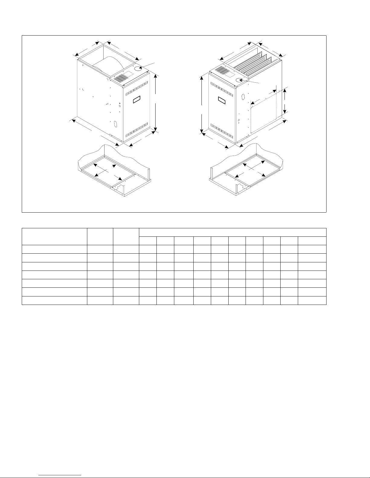
CABINET AND DUCT DIMENSIONS
BTUH (kW)
Input
G8C05012(MU,MD)B12
G8C07512(MU,MD)B12
G8C07516(MU,MD)C12
G8C10016(MU,MD)C12
G8C10020(MU,MD)D11
G8C12520(MU,MD)D11
G8C15020UHD11
1. 4-position models may be factory configured as upflow (MU) or downflow (MD).
2. 3-position 150 MBH model available only in upflow/horizontal (UH) configuration.
4. Dimensions “B”, “C”, “D”, and “E” are with duct flanges turned up. “F”, “G”, “H”, & “J” are with flanges flat.
3. All models are supplied with 3” (7.62 cm) vent connections. An installer supplied transition to 4” (10.16 cm) or 5” (12.7 cm) must be used where necessary.
Nominal
CFM
1
1200 B 17 1/2 16 1/2 20 3/8 20.0 16 14 3/4 18 3/4 15 1/8 19.0 3
1
1200 B 17 1/2 16 1/2 20 3/8 20.0 16 14 3/4 18 3/4 15 1/8 19.0
1
1600 C 21 20 20 3/8 20.0 19 1/2 18 1/4 18 3/4 18 5/8 19.0
1
1600 C 21 20 20 3/8 20.0 19 1/2 18 1/4 18 3/4 18 5/8 19.0
1
2000 D 24.5 23 1/2 20 3/8 20.0 23 21 3/4 18 3/4 22 1/8 19.0
1
2000 D 24.5 23 1/2 20 3/8 20.0 23 21 3/4 18 3/4 22 1/8 19.0
3
2000 D 24 1/2 23 1/2 20 3/8 20.0 23 21 3/4 18 3/4 22 1/8 19.0
Cabinet
Size
A(in.) B(in.) C(in.) D(in.) E(in.) F(in.) G(in.) H(in.) J(in.) K Vent (in.)
Cabinet Dimension
2
4
2
4
2
4
2
4
2
5
2
5
2 Unitary Products Group
Page 3
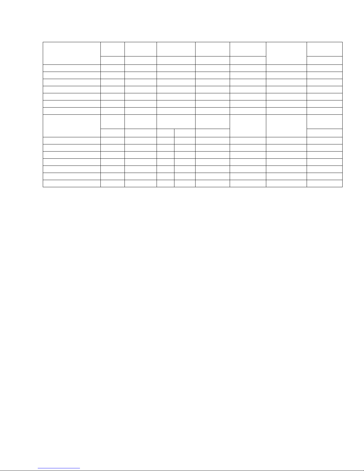
RATINGS & PHYSICAL / ELECTRICAL DATA - UPFLOW MODELS
270844-YTG-A-0407
Models
G8C05012(MU,MD)B12 50 40 1200 17-1/2 8.0 80.0 30-60
G8C07512(MU,MD)B12 75 60 1200 17-1/2 8.0 80.0 35-65
G8C07516(MU,MD)C12 75 60 1600 21 11.4 80.0 30-60
G8C10016(MU,MD)C12 100 80 1600 21 11.4 80.0 40-70
G8C10020(MU,MD)D11 100 80 2000 24 1/2 11.3 80.0 35-65
G8C12520(MU,MD)D11 125 100 2000 24 1/2 11.3 80.0 40-70
G8C15020UHD11 150 120 2000 24 1/2 11.3 80.0 40-70
Models
G8C05012(MU,MD)B12 50 160 1/2 7.0 10 x 8 15 14 112
G8C07512(MU,MD)B12 75 165 1/2 7.0 10 x 8 15 14 118
G8C07516(MU,MD)C12 75 160 1/2 10.4 10 x 10 15 14 129
G8C10016(MU,MD)C12 100 170 1/2 10.4 10 x 10 15 14 135
G8C10020(MU,MD)D11 100 165 1 10.3 (2)10 x 6 15 14 149
G8C12520(MU,MD)D11 125 170 1 10.3 (2)10 x 6 15 14 155
G8C15020UHD11 150 170 1 10.3 (2)10 x 6 15 14 165
Nominal external static pressure is 0.50” w.c. at furnace outlet ahead of cooling coils.
Annual Fuel Utilization Efficiency (AFUE) numbers are determined in accordance with DOE Test procedures.
Wire size and over current protection must comply with the National Electrical Code (NFPA-70-latest edition) and all local codes.
Input Output Nominal Airflow Cabinet Width
MBH MBH CFM In. Amps °F
Input
MBH °F Hp Amps In. LBS
Max. Outlet
Air Temp
Blower
Blower
Size
Total
Unit
Max
Over-current
protect
AFUE
Min.Wire Size
(awg) @ 75 ft.
one way
Air Temp.
Rise
Operation
Wt.
Unitary Products Group 3
Page 4
270844-YTG-A-0407
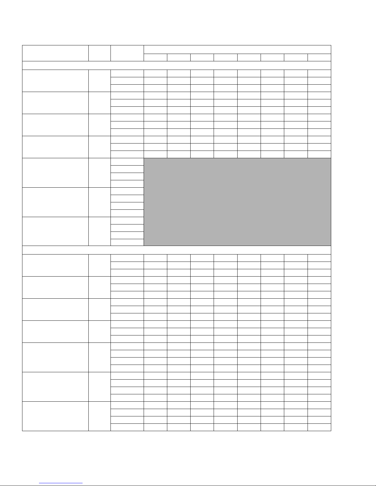
BLOWER PERFORMANCE
BTU/H (kW)
Input
G8C05012(MU,MD)B12
G8C07512(MU,MD)B12
G8C07516(MU,MD)C12
G8C10016(MU,MD)C12
G8C10020(MU,MD)D11
G8C12520(MU,MD)D11
G8C15020UHD11
2
G8C05012(MU,MD)B12
G8C07512(MU,MD)B12
G8C07516(MU,MD)C12
G8C10016(MU,MD)C12
G8C10020(MU,MD)D11
G8C12520(MU,MD)D11
G8C15020UHD11
2
1
1
1
1
2
3
1
1
1
1
2
2
Cabinet
Size
B
B
C
C
D
D
D
B
B
C
C
D
D
D
Speed
Tap
0.10.20.30.40.50.60.70.8
External Static Pressure, Inches WC - CFM
UPFLOW, SINGLE SIDE RETURN (WITHOUT FILTER)
High 1411 1360 1289 1218 1154 1075 983 882
Med 1213 1177 1134 1085 1022 960 880 782
Low 887 884 871 848 814 775 726 656
High 1535 1470 1408 1343 1275 1202 1115 1014
Med 1215 1199 1182 1151 1106 1039 976 887
Low 875 874 864 847 827 799 736 658
High 1792 1724 1630 1552 1462 1367 1264 1152
Med 1597 1555 1496 1444 1372 1287 1190 1086
Low 1115 1140 1167 1183 1149 1093 1023 939
High 1868 1781 1690 1600 1498 1396 1277 1156
Med 1602 1553 1503 1447 1376 1287 1181 1060
Low 1147 1147 1147 1147 1132 1078 1009 918
High
Med-High
Med-Low
Low
High
Med-High
Med-Low
NOT ALLOWED
Low
High
Med-High
Med-Low
Low
DUAL RETURN (TWO SIDES OR ONE-SIDE & BOTTOM)
High 1507 1433 1371 1300 1223 1132 1040 938
Med 1239 1215 1175 1144 1085 1012 938 838
Low 907 907 891 875 849 800 741 672
High 1634 1562 1484 1417 1340 1238 1154 1030
Med 1243 1228 1214 1184 1133 1079 999 912
Low 886 886 886 886 865 823 777 700
High 1978 1896 1803 1693 1589 1478 1366 1235
Med 1682 1657 1606 1530 1455 1366 1265 1137
Low 1235 1235 1235 1235 1198 1154 1083 987
High 2122 2027 1916 1821 1717 1590 1462 1312
Med 1667 1696 1656 1597 1523 1438 1330 1191
Low 1130 1145 1177 1194 1181 1146 1077 982
High 2350 2248 2129 2015 1876 1745 1596 1425
Med-High 2122 2018 1926 1824 1722 1606 1458 1311
Med-Low 1958 1875 1782 1690 1608 1491 1364 1213
Low 1820 1757 1664 1594 1506 1405 1287 1137
High 2483 2392 2282 2161 2032 1887 1739 1567
Med-High 2198 2123 2039 1930 1830 1708 1550 1413
Med-Low 1999 1916 1859 1778 1684 1576 1451 1315
Low 1832 1775 1709 1642 1556 1450 1335 1209
High 2570 2462 2361 2244 2128 1983 1826 1655
Med-High 2205 2105 2033 1952 1865 1738 1617 1459
Med-Low 1993 1931 1869 1880 1708 1590 1485 1330
Low 1831 1782 1722 1660 1575 1477 1364 1231
4 Unitary Products Group
Page 5
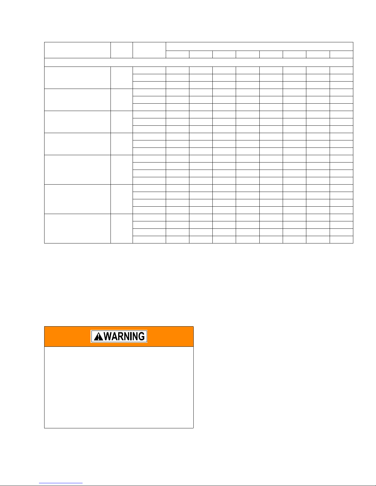
BLOWER PERFORMANCE (CONTINUED)
270844-YTG-A-0407
BTU/H (kW)
Input
G8C05012(MU,MD)B12
G8C07512(MU,MD)B12
G8C07516(MU,MD)C12
G8C10016(MU,MD)C12
G8C10020(MU,MD)D11
G8C12520(MU,MD)D11
G8C15020UHD11
1. Return air is through side opposite motor (left side) for one side return (worst case).
2. Airflows above 1800 CFM (50.97 m
3. Airflows expressed in standard cubic feet per minute (CFM) and in cubic meters per minute (m
Cabinet
Size
1
B
1
B
1
C
1
C
2
D
2
D
2
D
3
Speed
Tap
High 1419 1357 1297 1212 1131 1050 942 846
Med 1221 1185 1145 1092 1036 961 879 780
Low 920 902 883 860 818 761 711 639
High 1552 1491 1420 1348 1271 1185 1080 970
Med 1229 1237 1198 1164 1105 1039 956 861
Low 889 892 879 866 846 807 760 689
High 1946 1862 1775 1620 1518 1409 1291 1160
Med 1683 1611 1551 1484 1388 1300 1190 1080
Low 1110 1138 1175 1190 1175 1126 1041 937
High 1997 1920 1822 1723 1620 1500 1355 1211
Med 1728 1679 1635 1556 1465 1359 1249 1117
Low 1131 1156 1181 1190 1171 1126 1049 926
High 2327 2232 2121 1999 1888 1763 1628 1473
Med-High 2050 1967 1868 1757 1658 1525 1403 1260
Med-Low 1911 1839 1758 1675 1593 1468 1340 1189
High 1780 1712 1642 1566 1465 1366 1249 1094
High 2397 2304 2192 2063 1955 1822 1678 1521
Med-High 2151 2063 1977 1881 1774 1652 1528 1377
Med-Low 1972 1906 1838 1748 1660 1551 1419 1282
Low 1845 1794 1721 1646 1559 1451 1344 1208
High 2488 2389 2276 2151 2024 1883 1730 1577
Med-High 2164 2084 2024 1920 1816 1692 1558 1395
Med-Low 1998 1934 1868 1773 1673 1567 1445 1294
Low 1843 1793 1728 1653 1553 1453 1328 1192
/min) require either return from two sides or one side plus bottom
0.10.20.30.40.50.60.70.8
BOTTOM/END RETURN
External Static Pressure, Inches WC - CFM
3
/min).
RETURN AIR AND FILTERS
The return air ducts to the furnace must have a total cross
sectional area of not less than two square inches per 1000
BTUH of furnace input rating for heating operation. If air con-
ditioning is to be inst alled with th e furnace, or if it may be
added at a later time, larger return air ducts may be
required, depending on the capacity of the air conditioner and the airflow required.
For applications requiring more than 1800 CFM, it
is required to use the bottom return, both side
returns or one side plus the bottom return.
• Single side return is not approved on 5 Ton models.
• 18” minimum height for return air box for bottom
return only on Heating only applications with furnace in the upflow configuration.
• 24” minimum height for return air box for bottom
return only on A/C applications with furnace in
the upflow configuration.
FILTER PERFORMANCE
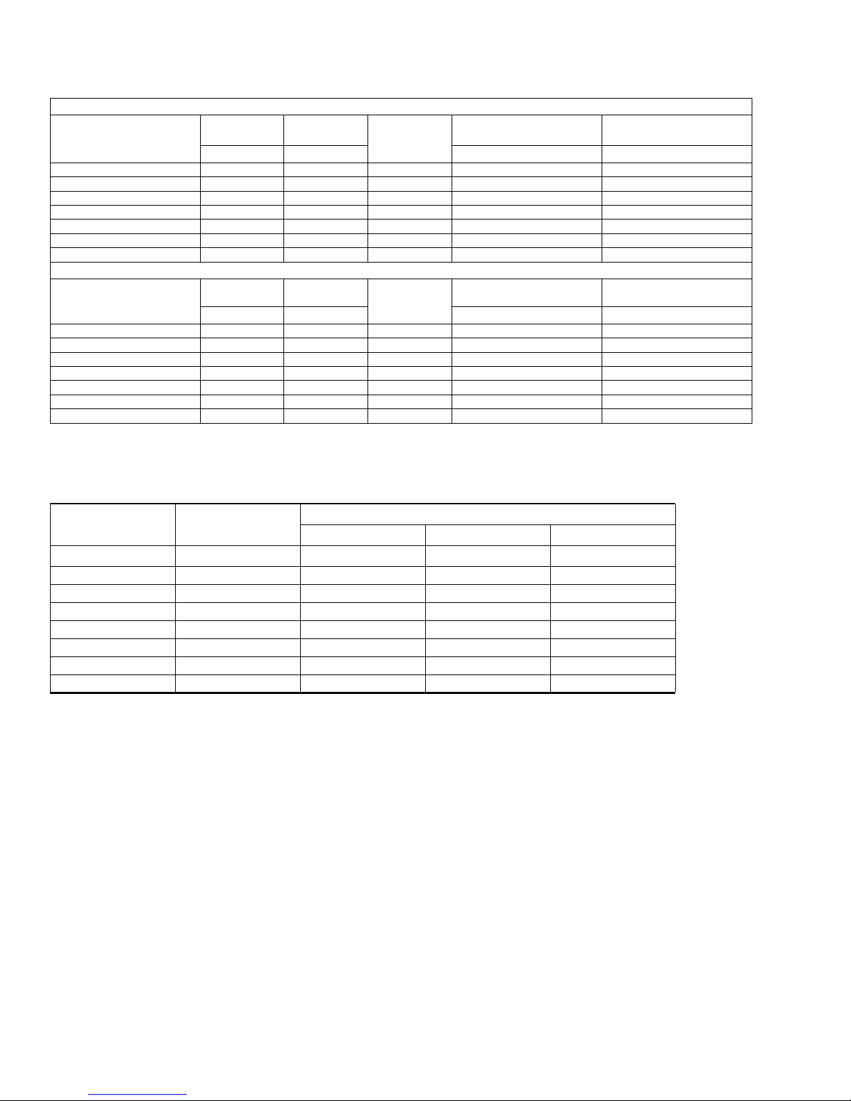
The airflow capacity data published in the “Blower Performance” table listed above represents blower performance
WITHOUT filters. To determine the approximate blower performance of the system, apply the filter drop value for the filter being used or select an appropriate value from the “Filter
Performance” table shown.
The filter pressure drop values in the “Filter Performance”
table shown are typical values for the type of filter listed and
should only be used as a guideline. Actual pressure drop ratings for each filter type vary between filter manufacturers.
Unitary Products Group 5
Page 6
270844-YTG-A-0407
RECOMMENDED FILTER SIZE
UPFLOW
Side
Return
Models
Input Air Flow
MBH CFM in. in.
Cabinet
Size
G8C05012(MU,MD)B12 50 1200 B 25 x 16 25 x 16
G8C07512(MU,MD)B12 75 1200 B 25 x 16 25 x 16
G8C07516(MU,MD)C12 75 1600 C 25 x 16 25 x 20
G8C10016(MU,MD)C12 100 1600 C 25 x 16 25 x 20
G8C10020(MU,MD)D11 100 2000 D (2) 25 x 16 24 x 24
G8C12520(MU,MD)D11 125 2000 D (2) 25 x 16 24 x 24
G8C15020UHD11 150 2000 D (2) 25 x 16 24 x 24
DOWNFLOW
Top Return (Downflow)
Cleanable Air Filters
Models
Input Air Flow
MBH CFM in. in.
Cabinet
Size
G8C05012(MU,MD)B12 50 1200 B 14 x 20 (2) 10 x 20
G8C07512(MU,MD)B12 75 1200 B 14 x 20 (2) 14 x 20
G8C07516(MU,MD)C12 75 1600 C 16 x 20 (2) 16 x 20
G8C10016(MU,MD)C12 100 1600 C 16 x 20 (2) 16 x 20
G8C10020(MU,MD)D11 100 2000 D 20 x 20 (2) 20 x 20
G8C12520(MU,MD)D11 125 2000 D 20 x 20 (2) 20 x 20
G8C15020UHD11 150 2000 D N/A N/A
NOTES:
1. Air velocity through throwaway type filters may not exceed 300 feet per minute. All velocities over this require the use of high velocity filters.
2. Air flows above 1800 CFM require either return from two sides or one side plus bottom.
Bottom/End
Return
Top Return (Downflow)
Disposable Air Filters
FILTER PERFORMANCE - PRESSURE DROP INCHES W.C. AND (KPA)
Airflow Range
CFM
Minimum
Opening Size
2
in
Disposable Washable Fiber Pleated
In W.C. In W.C. In W.C.
0 - 750 230 0.01 0.01 0.15
751 - 1000 330 0.05 0.05 0.20
1001 - 1250 330 0.10 0.10 0.20
1251 - 1500 330 0.10 0.10 0.25
1501 - 1750 380 0.15 0.14 0.30
1751 - 2000 380 0.19 0.18 0.30
2001 & Above 463 0.19 0.18 0.30
Filter Type
6 Unitary Products Group
Page 7

270844-YTG-A-0407
APPLYING FILTER PRESSURE DROP T O
DETERMINE SYSTEM AIRFLOW
To determine the approximate airflow of the unit with a filter in
place, follow the steps below:
1. Select the filter type.
2. Select the number of return air openings or calculate the
return opening size in square inches to determine the
proper filter pressure drop.
3. Determine the External System Static Pressure (ESP)
without the filter.
4. Select a filter pressure drop from the table based upon
the number of return air openings or return air opening
size and add to the ESP from Step 3 to determine the
total system static.
5. If total system static matches a ESP value in the airflow
table (i.e. 0.20 w.c., 0.60 w.c., etc.,) the system airflow
corresponds to the intersection of the ESP column and
Model/Blower Speed row.
6. If the total system static falls between ESP values in the
table (i.e. 0.58 w.c., 0.75 w.c., etc.), the static pressure
may be rounded to the nearest value in the table determining the airflow using Step 5 or calculate the airflow by
Example: For a 75,000 BTUH furnace with 2 return openings
and operating on high-speed blower, it is found that total system static is 0.38” w.c. To determine the system airflow, complete the following steps:
Obtain the airflow values at 0.30 w.c. & 0.40 w.c. ESP.
Airflow @ 0.30”: 1408 CFM
Airflow @ 0.40”: 1343 CFM
Subtract the airflow @ 0.30 w.c. from the airflow @ 0.40 w.c.
to obtain airflow difference.
1343 - 1408 = -65 CFM
Subtract the total system static from 0.30 w.c. and divide this
difference by the difference in ESP values in the table, 0.40
w.c. - 0.30 w.c., to obtain a percentage.
(0.38 - 0.30) / (0.40 - 0.30) = 0.8
Multiply percentage by airflow difference to obtain airflow
reduction.
(0.8) X (-65) = -52
Subtract airflow reduction value to airflow @ 0.30 w.c. to
obtain actual airflow @ 0.38 in. w.c. ESP.
1408 - 52 = 1356
using the following example.
UNIT CLEARANCES TO COMBUSTIBLES
Application Top Front Rear Left Side
Upflow 1 6 0 0 0 6 Combustible Yes Yes Yes No
Upflow
B-Vent
Horizontal 0 6 0 0 1 6 Combustible No Yes Yes
Horizontal
B-Vent
Downflow 1 6 0 0 5* 6
Downflow
B-Vent
1. Special floor base or air conditioning coil required for use on combustible floor.
2. Line contact only permitted between lines formed by the intersection of the rear panel and side panel (top in horizontal position) of
the furnace jacket and building joists, studs or framing.
*
Cabinet clearance is "0", vent clearance is required.
1 2 0 0 0 1 Combustible Yes Yes Yes No
1 2 0 0 1 1 Combustible No Yes Yes
12 0 0 01
Right
Side
Flue
Floor /
Bottom
1" (See Note
1" (See Note
Closet Alcove Attic
1
Yes Yes Yes No
)
)
Yes Yes Yes No
Line
Contact
Yes(See Note
Yes(See Note
2
)
2
)
ACCESSORIES
Propane Conversion Kit (Standard) – 1NP0366
This accessory conversion kit may be used to convert natural
gas units for propane (LP) operation at altitudes 0-2,000 ft.
Conversion must be made by qualified distributor or dealer
personnel.
Propane Conversion Kit (High Altitude) – 1PS0467
This accessory conversion kit may be used to convert natural
gas units for propane (LP) operation at altitudes from 2,000 to
8,000 ft. Conversion must be made by qualified distributor or
dealer personnel.
Natural Gas Conversion Kit (High Altitude) – 1PS0466
This accessory conversion kit may be used to convert natural
gas units for high altitude operation at altitudes from 2,000 to
8,000 ft. Conversion must be made by qualified distributor or
dealer personnel.
Unitary Products Group 7
Combustible Floor Base
This accessory is used for downflow applications on combustible surfaces.
17-1/2" "B" Cabinets 1FB0318
21" "C" Cabinets 1FB0319
24-1/2" "D" Cabinets 1FB0320
Bottom External Filter Rack
This accessory is used to upflow/bottom return air applications. Packaged and sold in quantities of six (6).
17-1/2" "B" Cabinets 1BR0312BK
21" "C" Cabinets 1BR0316BK
24-1/2" "D" Cabinets 1BR0320BK
Page 8

NOTES
Subject to change without notice. Printed in U.S.A. 270844-YTG-A-0407
Copyright © by York International Corp. 2007. All rights reserved. Supersedes: 246657-YTG-C-0806
Unitary 5005 Norman
Products York OK
Group Drive 73069
 Loading...