

Page 1
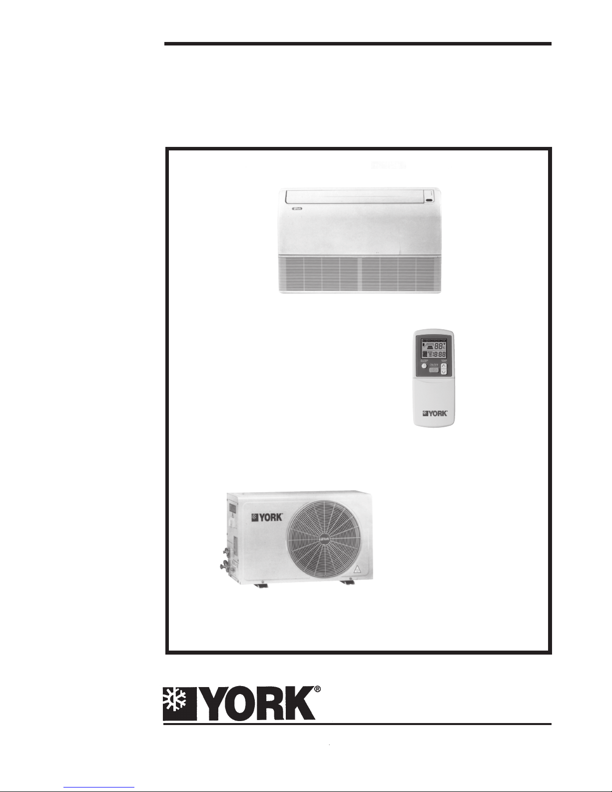
MOC - MOH
MCC - MCH
MINISPLIT
Floor / Ceiling
TECHNICAL GUIDE
Cooling only and Heat Pump Systems
Models MCC / MOC-MCH / MOH 09 to 25
Infrared remote control
035 T 700049 - 001
Page 2
Page
1
-
Safety...........................................................................................................................2
2
- Indoor and Outdoor units................................................................................................2
3
- Technical Specifications...............................................................................................3
4
- Dimensions..................................................................................................................3
5
- Installation....................................................................................................................4
6
- Condensate Drainage...................................................................................................6
7
- Refrigerant Piping Connections....................................................................................6
8
- Unit Controller Operation..............................................................................................7
9
- Filter Access.................................................................................................................8
10
- Wiring Diagram............................................................................................................9
11
- Service and Maintenance............................................................................................9
12
- Technical Appendix....................................................................................................10
13
- Accessories...............................................................................................................10
Parts List : (Contact York)
Decommissioning,Dismantling and Disposal
Installation and maintenance of this air conditioning system
should only be carried out by trained and qualified personnel.
Regular maintenace operations such as cleaning the coils and
air filters must be performed to keep the units in proper
operating condition.
CAUTION
Before undertaking any work on the unit, make sure that the
power supply has been disconnected.
ELECTRICAL CONNECTIONS
All electrical wiring and connections must comply with local
standards.Power supply cord used must not be lighter than
Polychloroprene sheated cord (245 IEC 57 or H05RN-F).
Disconnecting device must have a contact separation of at
least 3 mm.
GENERAL PRECAUTIONS
Check that the power supply available agrees with nameplate
voltage. Use adequate line protection.The unit must be grounded.
2
2.1 - Indoor Units
Each Unit is shipped with the following items:
- an indoor unit ready for connection to the condensing unit,
- a wireless remote controller supplied with batteries,
- a user's guide,
- a technical guide.
- installation accessories (see section13)
2.2 - Outdoor Units
The units are shipped complete with a charge of R22 refrigerant sufficient for a piping length of 5 metres.
List of Contents
1 - Safety
2 - Indoor & Outdoor Units
Page 3
3
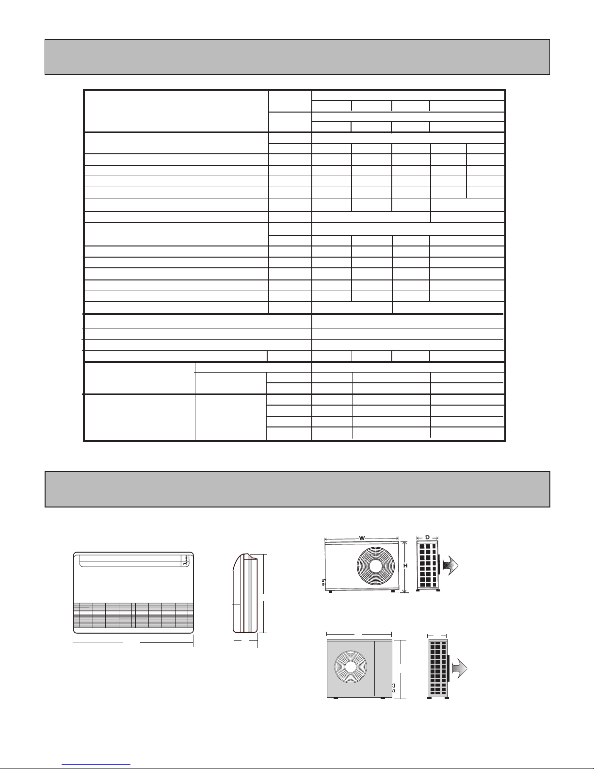
Unit dimensions are shown in the Technical Specifications table above.
Outdoor Unit : MOC/MOH 09-18
C
B EA D
Outdoor Unit : MOC/MOH 25
W
D
H
H
D
W
Indoor Unit : MCC/MCH 09-25
1
1.25
5.7
29
10
590
920/1,050
1/2"
1/4"
655/492
990/764
199/230
26/38
1
2.4
11.3
53
16
710
1,620
5/8"
3/8"
655/590
990/820
199/280
27/59
1
1.01
5
21.5
10
490
900/1,000
3/8"
1/4"
655/492
990/764
199/230
26/36
V/Ph/Hz
Ph
kW
A
A
A
m /h
Type
gr.
Suction
Liquid
H(mm)
W(mm)
D(mm)
kg
1
3.14
14.5
70
20
840
1,750
5/8"
3/8"
655/696
990/850
199/287
29/65
3
Models
Power Supply
Power Consumption
Nominal Current
Starting Current
Fuse Size
Indoor Airflow (high speed)
Indoor
unit
Outdoor
unit
V/Ph/Hz
Ph
kW
A
A
A
m /h
09
09
1
0.99
4.6
21
10
490
12
12
1
1.30
6.1
28
10
580
18
18
1
1.89
8.7
43
16
700
Refrigerant
Refrigerant Charge (MOC/MOH)
Piping
Dimensions and Weights
Indoor/Outdoor
Connection Type
Indoor Airflow (high speed)
Power Supply
208-230/1/60
Compressor
Starting Current
Fuse Size
Nominal Current
Power Consumption
Expansion Device
System Operation Control
Compressor
Wired or Wireless Remote Control with LCD Display
Capillary Tube
R22
Rotary
Rotary
Reciprocating
Reciprocating
220-240/1/50 or 380-415/3/50
3
2.73
5.4
34
10
25
25
820
1
2.80
13.2
68
20
3
Flare and Nuts
Diameter
MOC - MOH
MCC - MCH
3 - Technical Specifications
4 - Dimensions
Page 4
4
Unit installation entails:
- unit mounting
- refrigerant piping connections
- condensate water drainage connections
- unit wiring connections.
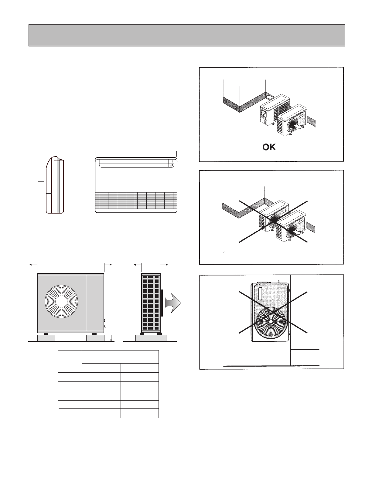
5.1 - Unit clearances
A minimium of clearance is necessary around the units to
ensure proper air circulation and easy access for maintenance.
Clearance required for indoor units
Clearance required for outdoor units
Outdoor unit placement
C
B EA D
Unit
A
B
C
D
E
09 to 18
400
200
100
200
600
25
400
200
100
250
600
MOC -MOH
↑
↓
←
→
200200
500
800
50
←
5 - Installation
Page 5
5
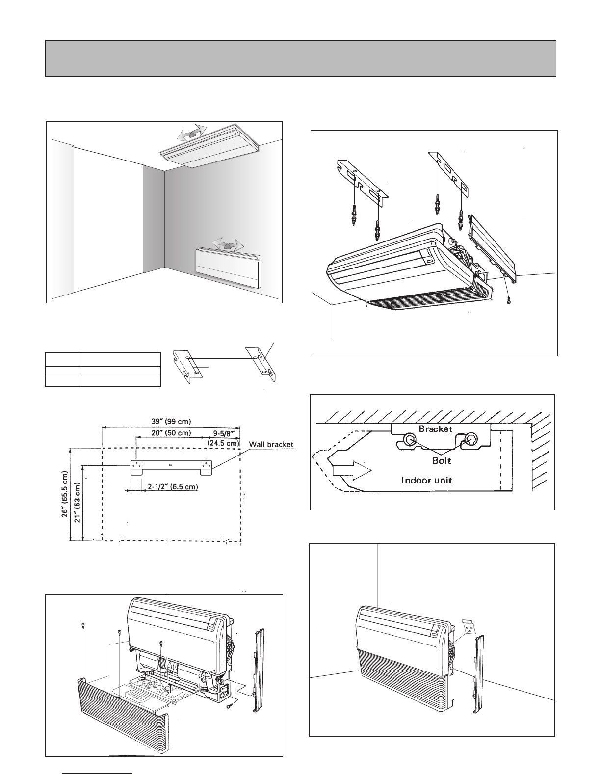
Indoor unit installation
Units can be installed vertically at floor level or horizontally
beneath a ceiling.
Under Ceiling
A
MCC -MCH 09-25
90 cm.
20 cm.
A
B
Bracket
Drill holes for fastners to attach brackets to wall or ceiling.
Use 12 mm. fastners suitable for the wall or ceiling material.
Wall Mount
Now, securely tighten the hex bolts on both sides.
Disassemble the side panels and the air inlet grill as shown.
First open the grill,then remove the side panel installation
screws. Slide the panel toward the top of the unit to detach it.
Dissasembly
Wall Mount
Installation Views
Unit installs easily under the ceiling or on the wall. After unit
is secure, side panels should be assembled again as shown.
side panel
installation screw
Under Ceiling
Slide the unit into the brackets as shown below.
B
5 - Installation (Cont'd)
Page 6
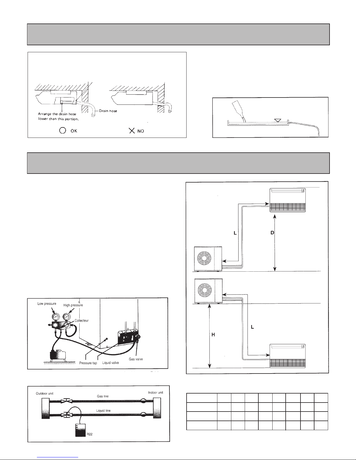
Prefabricated refrigerant piping is available as an accessory.
If this is not used, piping and insulating materials employed
must be compatible with this type of installation.
Indoor unit gas and liquid line connectors are mounted on
annealed copper tubing stubs and may be shaped to suit the
connection arrangements of your choice. Use the knock-outs
provide in the unit casing. Do not bend stubs to tight angles.
The pre-charged outdoor unit does not require charging if
piping length is 5m or less. However, the interconnecting
piping and the indoor unit must be pumped down before
releasing R22 refrigerant into them from the outdoor unit.
1 - Remove the cap from the service valve.
2 - Connect the line to a vacuum pump and pump down
to 5 Pa.
3 - When pump down is finisned, wait 15 minutes to detect
potential circuit leakage. Open service valves on the
outdoor unit.
* Note : The expansion device is located in the outdoor unit.
6
Table 2 - Maximum piping lengths
Note : Where the difference in elevation is greater than 5 metres,
install an oil trap every 5 metres.
Unit size
D(m)
L(m)
H(m)
7
10
15
12
9
10
15
12
12
12
18
15
18
12
18
15
25
20
25
22
35
20
25
22
45
24
30
26
55
24
30
26
If piping length exceeds 7.5 metres, add 15g of refrigerant
R22 per extra metre.
Install the drain hose.
Be sure to arrange the drain hose so that it is
leveled lower than the drain hose connecting
port of the indoor unit.
Drain tube on unit is flexible and can be routed to
suit various piping arrangements. The drainage
line must include an elbow trap (U bend).
Verification of condensate water drainage :
Fill the drain pan and observe evacuation.
6 - Condensate Drainage
7 - Refrigerant Piping Connections
Page 7

7
7
7
Units are equipped with a switch to run in emergency operation mode.
The switch is on the infrared receiver board where the LED lights are
located, or in the case of wall mount units it can be accessed by
opening the front grill. This switch is used for manual operation upon
expiration of service life of remote control batteries, or upon occurrence of a problem. Pushing the emergency switch first turns it on;
pushing it again turns if off (toggle action). During emergency
operation, the remote controller cannot be used and the power LED
light will flash in intervals, while the other LED lights will indicate
the operation of the Diagnostic Codes.
In Emergency Operation in cool mode, the temperature will be set at
24°C and the fan on Auto. In heating the unit will switch to auto mode
at a temperature set point of 24°C and the fan will run on auto mode.
EMERGENCY OPERATION
AUTO RESTART FUNCTION
Upon suspension of electrical power supply during operation for any
reason, when supply of power resumes the unit operation will restart
automatically according to all parameters set before the suspension
of power.
ANTI-ICE AND ANTI OVERHEATING
This feature is used to prevent the evaporator unit from freezing during cool or dry operation. During execution of anti-ice operation and
anti-overheating, the compressor will stop operating and the fan will
continue to run until the coil temperature reaches predetermined set
points, at which time the unit will resume normal operation.
LOW VOLTAGE
The feature is used to protect against any damage to the unit caused
by fluctuation of voltage. If voltage is lower than the lower limit for
approximately 10 seconds or longer, compressor operation will be
temporarily stopped. Normal operation will resume when the voltage
returns above the set limit for a minimum of 10 seconds. If the time
elapsed is less than 3 minutes then the compressor start up will be
delayed until 3 minutes has passed.
There are five different operating modes;
Cool Only and Heat Pump Units
-Cooling mode Heat Pump Units Only
-Dry mode - Automatic mode
-Fan mode (only on Cooling units) - Heating mode
The required mode can be selected by pressing the System button
until the corresponding mode symbol appears on the display. In automatic mode the unit operates automatically between Cool and Heat
modes based on the change in the room temperature and the
temperature set point entered on the control.
SYSTEM OPERATION MODE SELECTION
ROOM TEMPERATURE SETTING
Press the TEMP button up or down to change the setting to the desired
room temperature. The setting range is from 16°C to 32°C.Operating
the unit below 18°C may result in the coil freezing.
FAN SPEED AND LOUVER POSITION SETTING
Low - Medium - High speeds are available. Press the FAN button for
the desired air flow. The FAN symbol shows the speed that has been
selected.
Automatic fan speed is available in Cooling and Heat modes only.
When the dehumidification mode is used, the fan speed is set automatically.
The Sweep button is used to control the movement of the air louvers.
By pressing the button, the louver can be set in either the fixed position
or by pressing again, it will move in a sweeping motion to distribute
the air in the room.
Applicable only for units with air sweep.
FILTER CARE AND FILTER ALARM
To keep your air conditioning unit in peak condition, the filters should
be cleaned regularly, i.e. once a month, or more frequently depending
on conditions. To do this;
-Remove the filters from the unit
-Wash them in soapy water (do not use detergent)
-Dry the filters and put them back in place on the unit.
To clean the unit casing, use a damp cloth.
The control is equipped with a filter Alarm; based on the hours of
operation, and indicated by all of the lights flashing (see the Diagnostic
Chart for details), to remind you to change the filter. To reset the alarm
press the Filter button on the remote control. If you fail to press the reset
button the alarm will automatically reset after 6 hours of operation.
CLOCK AND TIMER FUNCTIONS
To set the clock press the Clock button for at least 5 seconds, until the
Clock symbol flashes. Then use the timer buttons to set the desired
time. Finally, press the Clock button again to enter the time that has
been set.
The control is equipped with a timer that can set both start and stop
times for the unit. the operational settings that have been entered on
the control will be the ones that the control follows when it starts.
To use the timer function follow these steps;
Lights will indicate that the unit timer has been set.
STOP
1. With the unit on.
2. Press the stop button
3. Adjust the clock display to the
desired stop time
4. Press Enter
The STOP symbol will be shown
on the display, indicating that a
stop time has been programmed.
START
1. Turn the unit on.
2. Press the start button
3. Adjust the clock display to the
desired start time
4. Press Enter
The START symbol will be shown
on the display, indicating that a
start time has been programmed.
8 - Unit Controller Operation
Page 8
8
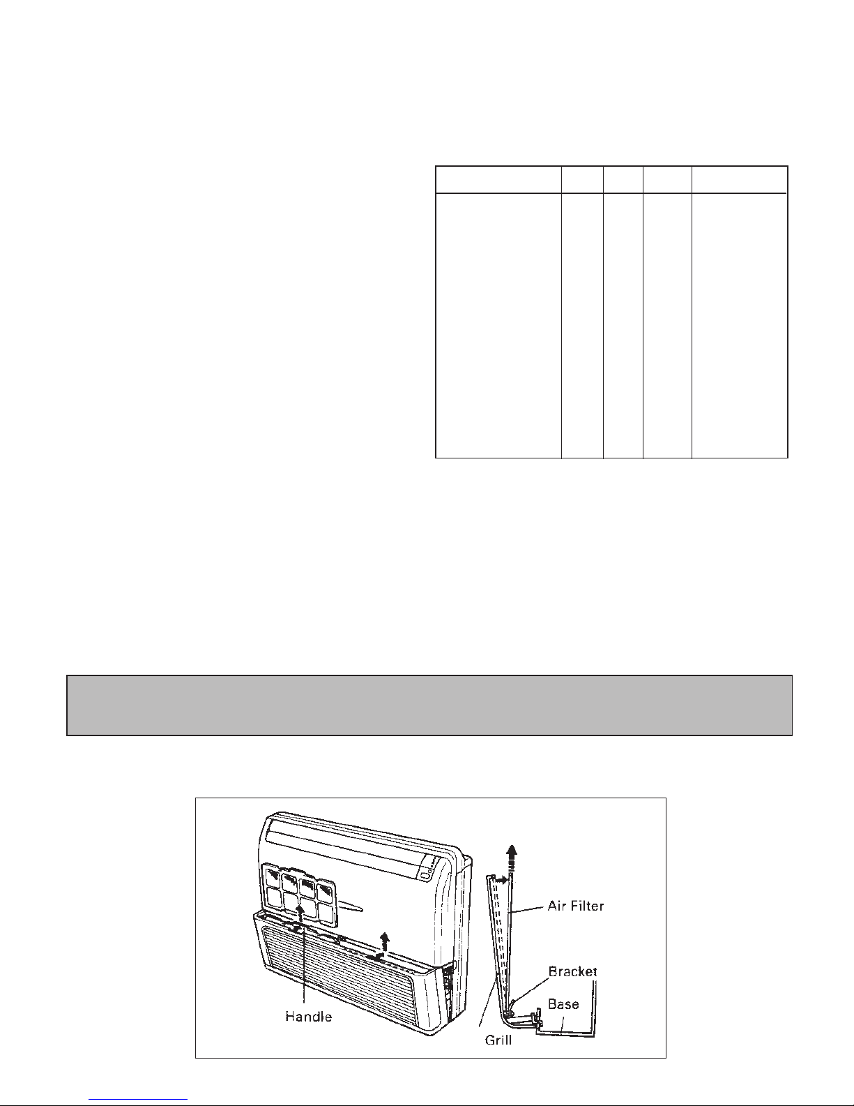
To remove filters, for cleaning or replacement, first open the grill, then pull filters up.
After the unit has either been started or stopped by the timer, the set
time will remain in the program, however the start or stop button must
be pressed again to reset the timer function.
To cancel either the Start or Stop Timer setting press the Cancel
button. To check the time that has been entered either for starting or
stopping the unit, press the appropriate start - stop button and the time
will be displayed. Press the button again to go back to the clock display.
SLEEP TIMER FUNCTION
Sleep mode, which can be used in Cool and Heat modes is a program
in the control which is designed to give a comfortable room environment during sleeping hours. At the start of sleep mode the unit will
operate in cooling or heating mode continuously until the temperature
set point is reached. It will then run for a further 1 hour period at this
setting. After this, the temperature set point will automatically be raised
+ 1° C every hour (cooling) or lowered -1°C every hour (heating) until
the sleep (shut off) time is reached. At this time the unit will shut off.
Sleep mode is set by pressing the sleep button which will set the shut
off time in 30 minute increments, starting from the time shown on the
clock when the sleep button is first pressed.
In sleep mode the unit will follow the settings that were entered at the
time that Sleep mode was started. Sleep mode can be canceled by
pressing the cancel button at any time.
DIAGNOSTIC INFORMATION FUNCTION
The control is equipped with a diagnostic information system to report
operation of the unit as well as operational failures. If your remote
control does not operate properly first check the polarity of the batteries
and that they are in good working condition. Also make sure that the
control is pointed directly at the air conditioning unit when you are using
it, that the distance is a maximum of 10 meters, and that there are no
obstacles between the remote control and the air conditioning unit.
The Diagnostic Information is reported via different flashing patterns
of the 3 indicator lights on the unit. The chart below shows the light
patterns for the various operational, protection and failure modes.
This feature is intended to provide information to the consumer as well
as for service of the units.
Status Power Timer Operation Mode
OFF(with power on)
ON (Temperature satisfied)
Waiting for delay
Compressor started
Sleep mode
Start timer set
Stop timer set
Low HP temp < 18°C
Coil temp > 40°C (cooling)
Overheat > 62° (heating)
Anti Freeze
Low voltage
Sensor fail
Cooling fail
Heating fail
Emergency operation
Test operation
Filter
O
X
X
X
X
X
X
X
X
X
X
F-2
F-1
F-2
F-3
F-3
F-1
F-3
O
O
F-1
O
X
F-2
F-3
O
O
F-1
F-2
O
O
O
O
Note 1
F-1
F-3
Normal Operation
Normal Operation
Normal Operation
Normal Operation
Normal Operation
Normal Operation
Normal Operation
Protection
Protection
Protection
Protection
Protection
Reset-Call Service Technician
Reset-Call Service Technician
Reset-Call Service Technician
Operational
Operational
Protection
O
O
O
X
X/O
X/O
X/O
F-1
F-2
F-1
F-2
O
F-1
F-2
F-3
Note 1
F-1
F-3
Notes
1) In emergency mode, the Power light will flash and the other lights will
indicate the operation as above.
2) Lights will flash during the time that the units is held off, due to Low
Voltage. If the voltage has passed through the reset voltage and the
unit is waiting for the time delay, the lights will go to normal operation.
3) The lights will show the LED Diagnostic Code even when the unit is
off.
X = ON, O = OFF, F-1 = ON : 0.5 sec, OFF : 0.5 sec
F-2 = ON : 1.5 sec, OFF : 0.5 sec
F-3 = ON : 0.5 sec, OFF : 1.5 sec
9 - Filter Access
Page 9
COMPONENT
E 1
2
1
N
A
E
2
Power Supply
220-240V/1Ph/50Hz
208-230V/1Ph/60Hz
N
2
3
23
N
E
N
1
EA
Power Supply
220-240V/1Ph/50Hz
208-230V/1Ph/60Hz
1
Outdoor unit
Power Supply
380-415V/3Ph/50Hz
Power Supply
380-415V/3Ph/50Hz
2
3
N
E
1
E
N12
RE
S
TN
12
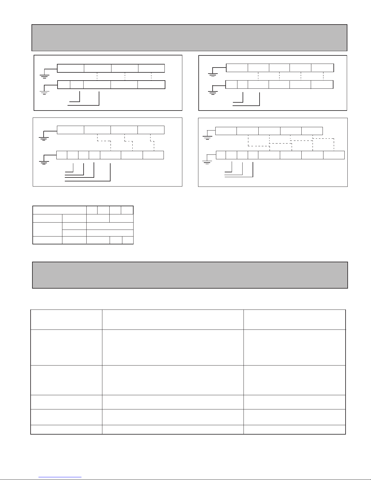
Table 3 - Wiring sizes
Unit size
Power supply
Fuse (slow-blow)
mm
2
2
2
Interconnection
(Indoor/Outdoor)
Cooling mm
Heating mm
A
2
RE
S
TN
1
3
3x2.5
10
For details of indoor unit and outdoor unit wiring, see the diagram
supplied inside the units. Start the unit and check operation both
in cooling and heating mode.
Indoor unit
Indoor
unit
Outdoor
unit
▲
▲
▲
▲
▲
▲
▲
MCH/MOH 25 - Heat Pump Units
MCH/MOH 09 - 25 - Heat Pump Units
Indoor
unit
▲▲▲▲
MCC/MOC 25 - Cooling Only Units
MCC/MOC 09 - 25 Cooling Only Units
Indoor
unit
Outdoor
unit
Outdoor
unit
9
The units are designed to operate for long periods of time with a minimum of maintenance. However, the following operations must be
performed regularly.
RECOMMENDED
FREQUENCY
MAINTENANCE OPERATIONS
1 - Clean with a vacuum cleaner or tap gently then
wash in warm water (40°C) with a mild detergent.
2 - Rinse and dry before replacing on unit.
3 - Never use petrol, alcohol or any other chemical
product.
1 - Remove dust from the front panel with a soft duster
or wipe a dump cloth with a mild soap solution.
2 - Never use petrol, alcohol or any other chemical
product.
1 - No maintenance required.
Drain pan and
evacuation piping
Unit casing
Air filter
Indoor / Outdoor coils
Compressor
1 - Check condition and remove dust from between
coil fins.
1 - Clean and check for obstructions.
Every month or more
often if necessary
Every month or more
often if necessary
Each season before start up.
Each season before start up.
9 12 18 25
3x2.5
3x4
4x2.5
16
20
10 - Wiring Diagram
11 - Service and Maintenance
Page 10
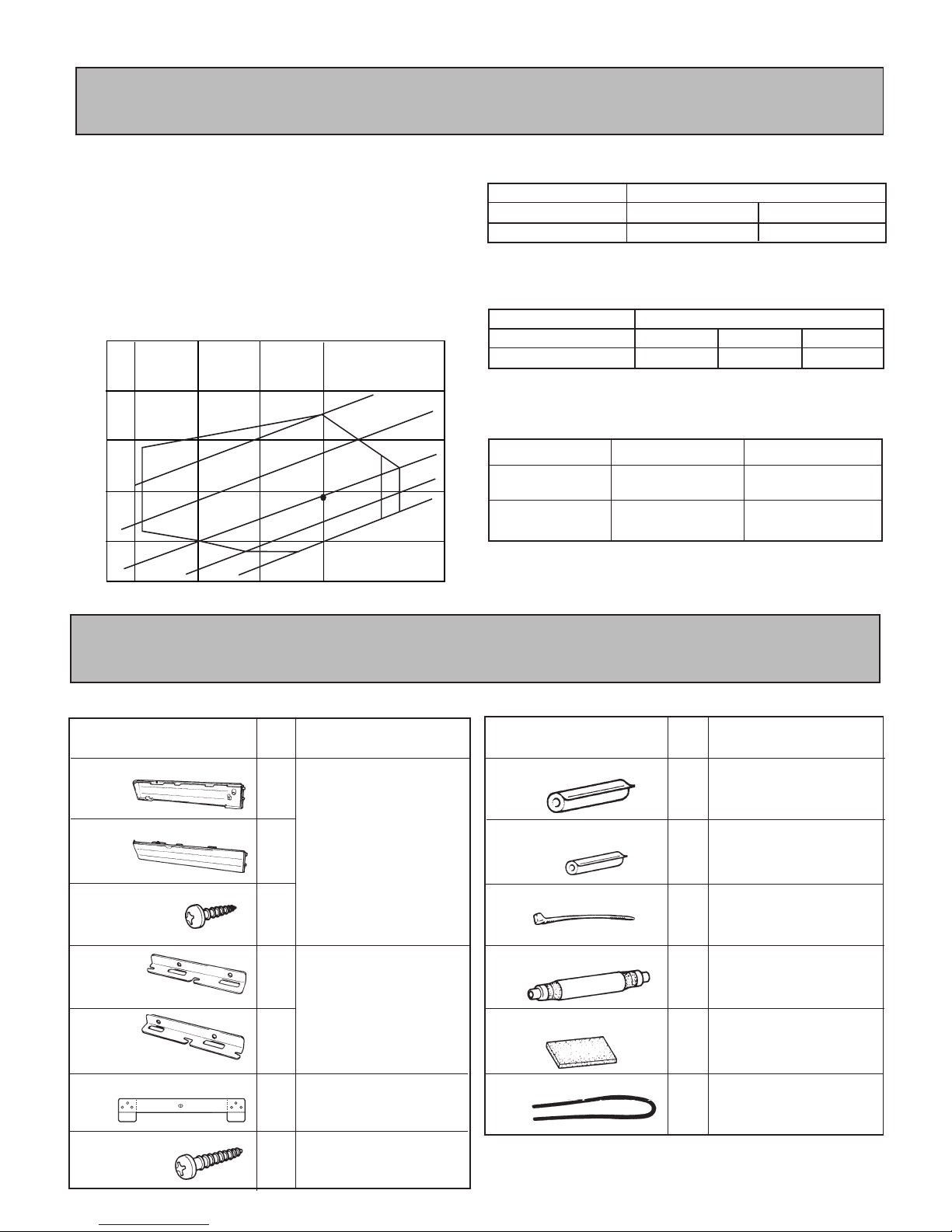
Unit Capacity
Total cooling capacity can be detemined by using correction factors C1, C2 and C3.
Given cooling capacity = Cooling capacity at standard
rating conditions x C1 x C2 x C3.
C1 = Capacity correction factor for tempetature
C2 = Capacity correction for piping length
C3 = Capacity correction for indoor unit fan speed
Capacity correction factor for temperature
Capacity correction factor for indoor fan speed (C3)
Fan speed
Correction factor C3
Indoor unit
High
1
Medium
0.90
Low
0.75
Indoor unit
10
0.98
7.5
1.00
Piping length (m)
Correction factor C2
Capacity correction factor for piping length (C2)
Operating temperature limits
Cooling mode
Heating mode
Maximum
+ 25°C
(heat pump mode)
+ 46°C
Minimum
+ 21°C
(-5 with low ambiant kit)
- 8°C
Inlet air wet bulb temperature,indoor unit (CWB)
10
15
20
25
30
35
20
25
30 35
40
Air intake dry bulb temperature, outdoor unit (CDB)
Capacity correction factor C1
Operating temperature range
110 %
100 %
90 %
85 %
120 %
R.C.
45
10
R.C. = Standard rating condition : Indoor 27°C DB / 19.5°C WB
Outdoor 35°C DB / 24°C WB
INDOOR UNIT INSTALLATION ACCESSORIES
Description Use
Description UseQ'ty
Q'ty
Bracket
(left)
Bracket
(right)
Wall bracket
Tapping screw
(Ø4x20)
Cover plate
(left)
Cover plate
(right)
Tapping screw
(Ø4x10)
Coupler heat insulater (small)
Coupler heat insulater (large)
Nylon fastener
Drain hose
Insulation (Drain hose)
VT wire
Hanging bracket for ceiling
installation
Bracket for wall installation
For indoor side pipe joint
(Small pipe)
For indoor side pipe joint
(Large pipe)
For indoor side pipe joint
(Small pipe)
For drain hose
Adhesive type
1
1
2
1
1
2
6
1
1
1
1
1
1
For drain hose
(L 280 mm)
12 - Technical Appendix
13 - Accessories
Page 11
CONFORMITY DECLARATION
AS DEFINED BY MACHINERY DIRECTIVE 89/392 EEC ANNEXE II A
WE : YORK Industrial (Thailand) Co., Ltd.
104 Moo 2, Teparak Rd., Tambon Bangsaothong
King-Ampher Bangsaothong. Samutprakarn 10540, Thailand.
DECLARE UNDER OUR OWN RESPONSIBILITY THAT THE MACHINE :
Outdoor unit MOC 07 to 55 and MOH 07 to 55
DESIGNATION :
Indoor units MCC 07 to 35 , MCH 07 to 35,
MSC 35 to 55, MSH 35 to 55,
MKC 12 to 55, MKH 12 to 55,
MAC 18 to 55, MAH 18 to 55
IS IN COMPLIANCE WITH REQUIREMENTS OF :
• MACHINERY DIRECTIVE CEE 89/392 AS MODIFIED WITH DIRECTIVES
CEE 91/368, 93/44, 93/68 (EEC 91/368, 93/44 AND 93/68)
• LOW VOLTAGE DIRECTIVE CEE73/23 (EEC 73/23)
• ELECTROMAGNETIC COMPATIBILITY DIRECTIVE CEE 89/336 (EEC 89/336)
EC type certificate TCF n° 277
IN ACCORDANCE WITH THE FOLLOWING HARMONIZED STANDARDS :
• EN 292/1, EN 292/2, EN 292-2A1, EN 60335-2-40, EN 50081-1, EN 50082-1
NAME : KACHIT
SURNAME : SRIMUNCHU
POSITION : ENGINEERING MANAGER
SIGNATURE :
11
Page 12
DE - COMMISSIONING DISMANTLING & DISPOSAL
This product contains refrigerant under pressure, rotating parts, and electrical connections which may be a danger and cause injury!
All work must only be carried out by competent persons using suitable protective clothing and safety precautions.
Read the Manual Risk of electric shock Unit is remotely controlled and may start without warning
1. Isolate all sources of electrical supply to the unit including any control system supplies switched by the unit. Ensure that all points of electrical and gas
isolation are secured in the OFF position. The supply cables and gas pipework may then be disconnected and removed. For points of connection refer
to unit installation instructions.
2. Remove all refrigerant from each system of the unit into a suitable container using a refrigerant reclaim or recovery unit. This refrigerant may then be
re-used, if appropriate, or returned to the manufacturer for disposal. Under No circumstances should refrigerant be vented to atmosphere. Where
appropriate, drain the refrigerant oil from each system into a suitable container and dispose of according to local laws and regulations governing
disposal of oily wastes.
3. Packaged unit can generally be removed in one piece after disconnection as above. Any fixing down bolts should be removed and then unit lifted
from position using the points provided and equipment of adequate lifting capacity. Reference MUST be made to the unit installation instructions for
unit weight and correct methods of lifting. Note that any residual or spilt refrigerant oil should be mopped up and disposed of as described above.
4. After removal from position the unit parts may be disposed of according to local laws and regulations.
 Loading...