

Page 1

FULL-CASED MULTI-POSITION FOR
ISO 9001
Certified Quality
Management System
INSTALLATION MANUAL
COOLING/HEAT PUMPS
MODELS: MC
FULL-CASED UPFLOW/COUNTERFLOW FOR
COOLING/HEAT PUMPS
MODELS: FC
PARTIAL-CASED UPFLOW FOR COOLING/HEAT PUMP
MODELS: PC
LIST OF SECTIONS
SAFETY . . . . . . . . . . . . . . . . . . . . . . . . . . . . . . . . . . . . . . . . . . . . . . . .1
GENERAL INFORMATION . . . . . . . . . . . . . . . . . . . . . . . . . . . . . . . . .2
COIL METERING DEVICES . . . . . . . . . . . . . . . . . . . . . . . . . . . . . . . . 4
COIL INSTALLATION . . . . . . . . . . . . . . . . . . . . . . . . . . . . . . . . . . . . .5
DUCT CONNECTIONS . . . . . . . . . . . . . . . . . . . . . . . . . . . . . . . . . . . .6
LIST OF FIGURES
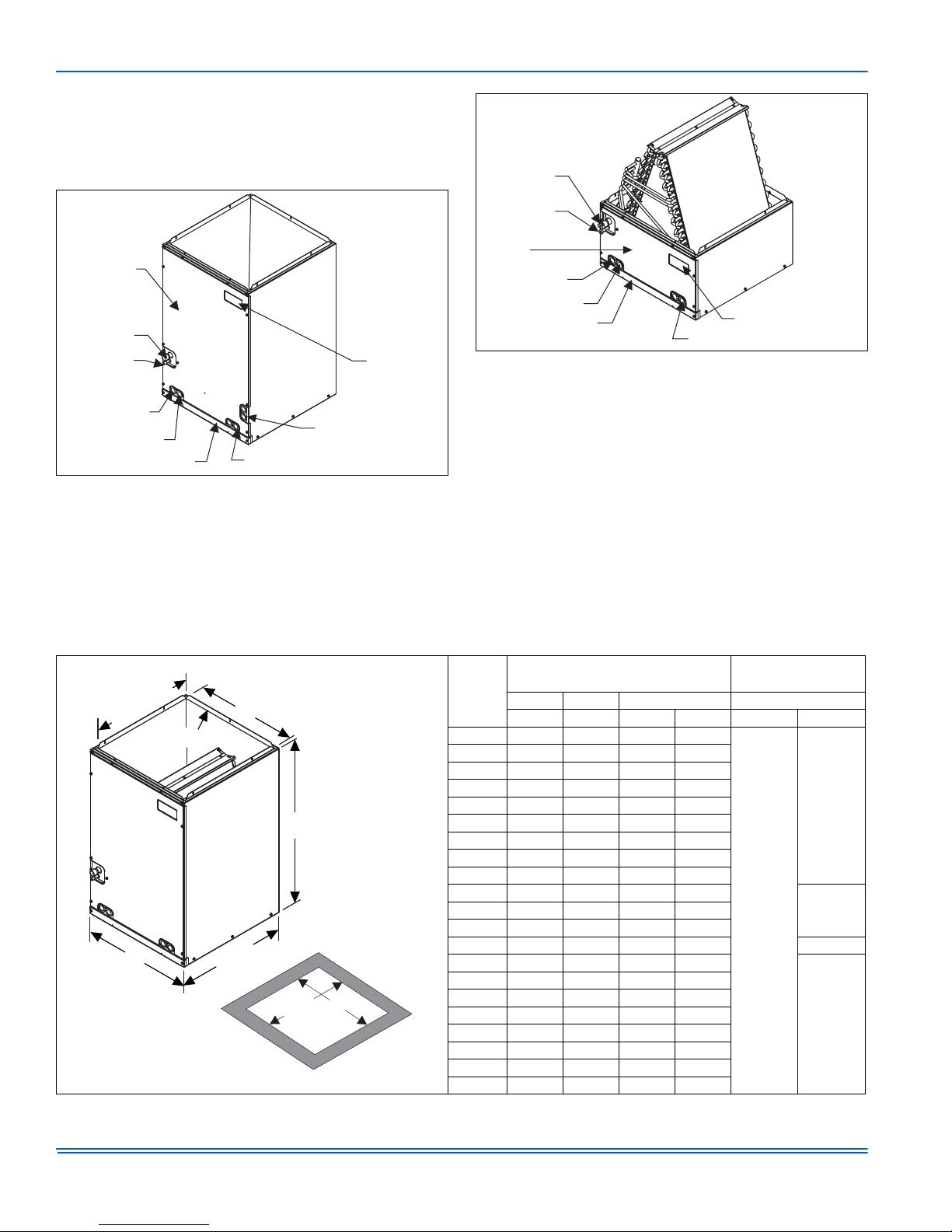
Component Location - Coil MC & FC . . . . . . . . . . . . . . . . . . . . . . . . . . 2
Component Location - Coil PC . . . . . . . . . . . . . . . . . . . . . . . . . . . . . . .2
TXV Bulb Installation . . . . . . . . . . . . . . . . . . . . . . . . . . . . . . . . . . . . . . 4
Proper Bulb Location . . . . . . . . . . . . . . . . . . . . . . . . . . . . . . . . . . . . . .4
Vertical Applications . . . . . . . . . . . . . . . . . . . . . . . . . . . . . . . . . . . . . . . 5
Coil Flange Placement . . . . . . . . . . . . . . . . . . . . . . . . . . . . . . . . . . . . .5
Coil Flange . . . . . . . . . . . . . . . . . . . . . . . . . . . . . . . . . . . . . . . . . . . . . .5
Horizontal Right Application . . . . . . . . . . . . . . . . . . . . . . . . . . . . . . . . .6
Horizontal Left Application . . . . . . . . . . . . . . . . . . . . . . . . . . . . . . . . . .6
CONDENSATE DRAIN CONNECTIONS . . . . . . . . . . . . . . . . . . . . . . .7
REFRIGERANT LINE CONNECTION . . . . . . . . . . . . . . . . . . . . . . . . .8
COIL CLEANING . . . . . . . . . . . . . . . . . . . . . . . . . . . . . . . . . . . . . . . . .8
AIR SYSTEM ADJUSTMENT . . . . . . . . . . . . . . . . . . . . . . . . . . . . . . .8
INSTALLATION VERIFICATION . . . . . . . . . . . . . . . . . . . . . . . . . . . . .9
Upflow Coil Installation . . . . . . . . . . . . . . . . . . . . . . . . . . . . . . . . . . . . .6
Condensate Deflector on Vertical Drain Pan . . . . . . . . . . . . . . . . . . . .7
Condensate Deflector on Horizontal Drain Pan Edge . . . . . . . . . . . . .7
S-Clip Installation . . . . . . . . . . . . . . . . . . . . . . . . . . . . . . . . . . . . . . . . .7
Pressure Check . . . . . . . . . . . . . . . . . . . . . . . . . . . . . . . . . . . . . . . . . .9
TXV Check List . . . . . . . . . . . . . . . . . . . . . . . . . . . . . . . . . . . . . . . . . . .9
Drain Traps . . . . . . . . . . . . . . . . . . . . . . . . . . . . . . . . . . . . . . . . . . . . . .9
Location of Trapped and Plugged Drain Connections . . . . . . . . . . . . .9
LIST OF TABLES
Dimensions - MC Coils . . . . . . . . . . . . . . . . . . . . . . . . . . . . . . . . . . . . .2
Dimensions - FC Coils . . . . . . . . . . . . . . . . . . . . . . . . . . . . . . . . . . . . .3
Dimensions - PC Coils . . . . . . . . . . . . . . . . . . . . . . . . . . . . . . . . . . . . .3
SECTION I: SAFETY
This is a safety alert symbol. When you see this symbol on
labels or in manuals, be alert to the potential for personal
injury.
Understand and pay particular attention to the signal words DANGER,
WARNING, or CAUTION.
DANGER indicates an imminently hazardous situation, which, if not
avoided, will result in death or serious injury
WARNING indicates a potentially hazardous situation, which, if not
avoided, could result in death or serious injury
CAUTION indicated a potentially hazardous situation, which, if not
avoided may result in minor or moderate injury. It is also used to alert
against unsafe practices and hazards involving only property damage.
Improper installation may create a condition where the operation of
the product could cause personal injury or property damage.
Improper installation, adjustment, alteration, service or maintenance can cause injury or property damage. Refer to this manual
for assistance or additional information, consult a qualified installer
or service agency.
.
.
Coil Air Flow Limits . . . . . . . . . . . . . . . . . . . . . . . . . . . . . . . . . . . . . . . .4
ECoil Projection Dimensions - PC Coils . . . . . . . . . . . . . . . . . . . . . . . .6
Air Flow Data - Static Pressure Drop . . . . . . . . . . . . . . . . . . . . . . . . . .8
This product must be installed in strict compliance with the
enclosed installation instructions and any applicable local, state,
and national codes including, but not limited to building, electrical,
and mechanical codes.
The furnace area must not be used as a broom closet or for any
other storage purposes, as a fire hazard may be created. Never
store items such as the following on, near or in contact with the furnace.
1. Spray or aerosol cans, rags, brooms, dust mops, vacuum
cleaners or other cleaning tools.
2. Soap powders, bleaches, waxes or other Cleaning compounds; plastic items or containers; gasoline, kerosene, cigarette lighter fluid, dry cleaning fluids or other volatile fluid.
3. Paint thinners and other painting compounds.
4. Paper bags, boxes or other paper products
Never operate the furnace with the blower door removed. To do so
could result in serious personal injury and/or equipment damage.
841890-UIM-B-0612
Page 2
841890-UIM-B-0612
Coil Access
Panel
Suction Line
Connection
Liquid Line
Connection
Alternate Drain Location
Label
Location
Drain Location
Horizontal Application
(on MC Coils Only)
Primary Drain
Secondary Drain
Bottom Door Panel
Label Location
Coil Access
Panel
Primary Drain
Secondary Drain
Bottom Door Panel
Alternate Drain Locations
Suction Line
Connection
Liquid Line
Connection
20 3/8”
(Opening)
B
C
3/4” Flange
A
21 1/2”
BOTTOM
OPENING
DIMENSIONS
D
20 1/4”
SECTION II: GENERAL INFORMATION
This instruction covers the installation of the following coils with 80+ or
90+ AFUE furnaces or MA/MX/MV air moving systems.
The coils have sweat connect fittings. All coils are shipped with a low
psi nitrogen holding charge.
FIGURE 1: Component Location - Coil MC & FC
INSPECTION
As soon as a coil is received, it should be inspected for possible damage during transit. If damage is evident, the extent of the damage
should be noted on the carrier’s delivery receipt. A separate request for
inspection by the carrier’s agent should be made in writing. See Local
Distributor for more information. Check drain pan for cracks or breakage.
FIGURE 2: Component Location - Coil PC
CLEARANCES
DURING INSTALLATION
Clearance must be provided for:
1. Refrigerant piping and connections
2. Maintenance and servicing access - including cleaning the coil
3. Condensate drain line
4. Filter removal / change
5. Removal of coil assembly
TABLE 1: Dimensions
- MC Coils
1. All dimensions are in inches.
2. Refrigerant line sizes may require larger lines for extended line lengths. See York bulletin #690.01-AD1V for details.
2
Dimensions
Models
MC18A 22 14 1/2 13 3/8 13 1/2
MC18B 22 17 1/2 16 3/8 16 1/2
MC24A 26 1/2 14 1/2 13 3/8 13 1/2
MC24B 26 1/2 17 1/2 16 3/8 16 1/2
MC30A 26 1/2 14 1/2 13 3/8 13 1/2
MC30B 26 1/2 17 1/2 16 3/8 16 1/2
MC32A 22 14 1/2 13 3/8 13 1/2
MC35B 22 17 1/2 16 3/8 16 1/2
MC35C 22 21 19 7/8 20
MC36A 26 1/2 14 1/2 13 3/8 13 1/2
MC36C 26 1/2 21 19 7/8 20
MC37A 26 1/2 14 1/2 13 3/8 13 1/2 3/4
MC42B 32 17 1/2 16 3/8 16 1/2
MC42C 32 21 19 7/8 20
MC43B 26 1/2 17 1/2 16 3/8 16 1/2
MC43C 26 1/2 21 19 7/8 20
MC48C 32 21 19 7/8 20
MC48D 32 24 1/2 23 3/8 23 1/2
MC60D 32 24 1/2 23 3/8 23 1/2
MC62D 36 24 1/2 23 3/8 23 1/2
Height Width Opening Widths Line Size
ABCDLiquidVapor
1
Refrigerant
Connections
3/8
3/4
7/8MC36B 26 1/2 17 1/2 16 3/8 16 1/2
7/8
2
Page 3

841890-UIM-B-0612
20 3/8”
(Opening)
B
C
3/4” Flange
A
21 1/2”
BOTTOM
OPENING
DIMENSIONS
D
20 1/4”
20 3/8”
(Opening)
B
C
(Opening)
12”
A
21 1/2”
BOTTOM
OPENING
DIMENSIONS
20 1/4”
D
TABLE 2: Dimensions
1. All dimensions are in inches.
2. Refrigerant line sizes may require larger lines for extended line lengths. See York bulletin #690.01-AD1V for details.
TABLE 3: Dimensions - PC Coils
1. All dimensions are in inches.
2. Refrigerant line sizes may require larger lines for extended line lengths. See York bulletin #690.01-AD1V for details.
- FC Coils
Dimensions
Models
FC18A 18 14 1/2 13 3/8 13 1/2
FC18B 18 17 1/2 16 3/8 16 1/2
FC24A 22 14 1/2 13 3/8 13 1/2
FC24B 22 17 1/2 16 3/8 16 1/2
FC30A 22 14 1/2 13 3/8 13 1/2
FC30B 22 17 1/2 16 3/8 16 1/2
FC32A 20 14 1/2 13 3/8 13 1/2
FC35B 20 17 1/2 16 3/8 16 1/2
FC35C 24 1/2 21 19 7/8 20
FC36A 24 1/2 14 1/2 13 3/8 13 1/2
FC36C 24 1/2 21 19 7/8 20
FC37A 24 1/2 14 1/2 13 3/8 13 1/2 3/4
FC42B 28 17 1/2 16 3/8 16 1/2
FC42C 28 21 19 7/8 20
FC43B 24 1/2 17 1/2 16 3/8 16 1/2
FC43C 24 1/2 21 19 7/8 20
FC48C 28 21 19 7/8 20
FC48D 28 24 1/2 23 3/8 23 1/2
FC60C 28 21 19 7/8 20
FC60D 28 24 1/2 23 3/8 23 1/2
FC62D 32 24 1/2 23 3/8 23 1/2
FC64D 36 24 1/2 23 3/8 23 1/2
Models
PC18A 17 3/4 14 1/2 13 3/8 13 1/2
PC18B 17 17 1/2 16 3/8 16 1/2
PC24A 21 7/8 14 1/2 13 3/8 13 1/2
PC24B 21 3/8 17 1/2 16 3/8 16 1/2
PC30A 21 7/8 14 1/2 13 3/8 13 1/2
PC30B 21 3/8 17 1/2 16 3/8 16 1/2
PC32A 20 14 1/2 13 3/8 13 1/2
PC35B 18 7/8 17 1/2 16 3/8 16 1/2
PC35C 18 3/4 21 19 7/8 20
PC36A 23 7/8 14 1/2 13 3/8 13 1/2
PC36C 22 7/8 21 19 7/8 20
PC37A 23 7/8 14 1/2 13 3/8 13 1/2 3/4
PC42B 27 5/8 17 1/2 16 3/8 16 1/2
PC42C 27 1/8 21 19 7/8 20
PC43B 23 1/8 17 1/2 16 3/8 16 1/2
PC43C 22 5/8 21 19 7/8 20
PC48C 25 3/8 21 19 7/8 20
PC48D 24 5/8 24 1/2 23 3/8 23 1/2
PC60C 27 1/2 21 19 7/8 20
PC60D 26 7/8 24 1/2 23 3/8 23 1/2
Height Width Opening Widths Line Size
ABCDLiquidVapor
Dimensions
Height Width Opening Widths Line Size
ABCDLiquidVapor
1
1
Refrigerant
Connections
3/4
7/8FC36B 24 1/2 17 1/2 16 3/8 16 1/2
3/8
7/8
Refrigerant
Connections
3/4
3/8
2
2
7/8PC36B 23 1/8 17 1/2 16 3/8 16 1/2
7/8
3
Page 4

841890-UIM-B-0612
NOTICE
Vapor
Line
Thermal
Expansion
Valve Bulb
Thermal
Expansion
Valve
Distributor
Body
Liquid
Line
TXV
Equalizer
Line
(Wrapped with
insulation)
TXV BULB
(Cover completely
with insulation)
SCREW
CLAMP
NUT
SUCTION LINE
NOTICE
LIMITATIONS
These coils should be installed in accordance with all national and local
safety codes.
TABLE 4:
60, 62, 64
Coil Air Flow Limits
Coil
Size
18 1-1/2 525 675
24
30, 32
35
36, 37
42
43
48
Outdoor Unit
Tons
1-1/2 525 675
2 700 900
2 700 900
2-1/2 875 1125
2-1/2 875 1125
3 1050 1200
2-1/2 875 1125
3 1050 1350
3 1050 1350
3-1/2 1225 1575
3 1050 1350
3-1/2 1225 1575
3 1050 1350
3-1/2 1225 1575
4 1400 1800
4 1600 1800
5 1750 2250
CFM Limits
Minimum Maximum
FIGURE 3: TXV Bulb Installation
SECTION III: COIL METERING DEVICES
An orifice or a TXV to be installed in the field. Refer to installation manual with TXV kit. It is recommended to install the orifice or TXV kit prior
to installation of coil in cabinet and brazing line sets.
Consult the outdoor installation guide for outdoor units that require an
orifice as a metering device for the indoor coil. The orifice and the
Schraeder core are supplied with the outdoor unit. Install Schraeder
core in the suction line Schraeder body and cap with the supplied plastic cap.
TXV METERING DEVICE
Please refer to Technical Guide to verify which TXV is installed in this
coil and that this is a valid system match for the AC or HP unit installed.
The temperature sensing bulb is attached to the coil suction header
line.
For models that have factory installed TXV’s, take caution not to
apply high temperatures to the TXV assembly or equalizer line
while brazing.
FIGURE 4: Proper Bulb Location
COIL UNDER PRESSURE.
Relieve pressure by depressing schrader stem. Coil may have factory installed TXV or may require orifice or TXV to be added. See
outdoor unit documentation for correct orifice or TXV to be used.
Refer to coil nameplate for orifice or TXV identification for this unit.
The coil should be open to the air for no more than 2 minutes to
keep moisture and contaminates from entering the system. If the
coil cannot be brazed into the refrigeration system in that time, the
ends should be temporarily closed or plugged. For a short term
delay, use masking tape over the ends of the copper tubing to close
the tube to the air. For a longer term delay, use plugs or caps.
There is no need to purge the coil if this procedure is followed.
4
Page 5

SECTION IV: COIL INSTALLATION
UPFLOW
DOWNFLOW
Furnace
Furnace
NOTICE
Alternate
Flange Location
Factory
Flange
Location
FIGURE 5: Vertical Applications
FURNACE ASSEMBLY - MC & FC
These coils are factory shipped for installation in either upflow or downflow applications with a minor conversion.
For Upflow Application:
1. Position the coil casing over or under the furnace opening as
shown in Figure 5 after configuring coil flanges as required see
“Coil Flange” section below and refer to Figure 7.
2. Slide up the sides and back flange and tight the 6 screws that hold
them. Refer to Figure 6.
3. Unscrew the front flange and move it to the top to align it to the
rest of the flanges allowing to screw it back to the brace using the
2 holes in the bottom of the front flange. Refer to Figure 6.
4. Place the ductwork over the coil casing flange and secure.See
sections on "Refrigerant L ine Connections" and "Condensate
Drain Connections". One mounting plate is provided with the coils.
For Downflow Application:
1. Position the coil casing over or under the furnace opening as
shown in Figure 5 after configuring coil flanges as required see
“Coil Flange” section below and refer to Figure 7.
2. Remove all 8 screws from flangs and position them at the bottom
of the casing for the alternate position. Refer to Figure 7.
3. Place the ductwork over the coil casing flange and secure.See
sections on "Refrigerant Line Connections" and "Condensate
Drain Connections". One mounting plate is provided with the coils
841890-UIM-B-0612
FIGURE 6: Coil Flange Placement
When installing this coil with an oil furnace, a minimum of six inches
clearance should be maintained from the top of the heat exchanger.
COIL FLANGE - FOR DOWNFLO W AND HORIZONT AL
LEFT KIT INSTALLATION
The coils include removable flanges to allow proper fit up with furnaces
or two-piece air handlers having various inlet and outlet flange configurations. The two flanges are attached to the top of the coil in the factory
during production. If the installation requires the flanges to be moved to
the bottom of the coil, remove the screws attaching the flanges to the
top of the coil casing. Next, install the flanges to the bottom of the coil
casing using the same screws. Refer to Figure 7.
The additional holes in the upper area of the flanges may be used to
attach the coil to the furnace or two-piece air handler. This is done by
installing field-supplied screws through the flanges into the inside of the
furnace or two-piece air handler casing.
The front flange is also designed so that it can be rotated 180 degrees
and re-installed. In this mounting configuration the front flange will
extend further to the front of the coil casing to accommodate furnaces
or two-piece air handlers that have a greater front-to-back dimension
than the coils.
FIGURE 7: Coil Flange
5
Page 6
841890-UIM-B-0612
Furnace
Furnace
NOTICE
NOTICE
Flexible Duct
Collar
DO NOT Drill or
Screw this Flange
Field
Fabricated
Ductwork
Upflow Coil
Upflow Furnace
Secondary Drain
Primary Drain
D
C
(Min.)
Alternate
Drain Location
FURNACE ASSEMBLY - (MC ONLY)
MC coils are supplied ready to be installed in a horizontal position. A
horizontal pan is factory installed. MC coils should be installed in all horizontal applications with the horizontal drain pan side down.
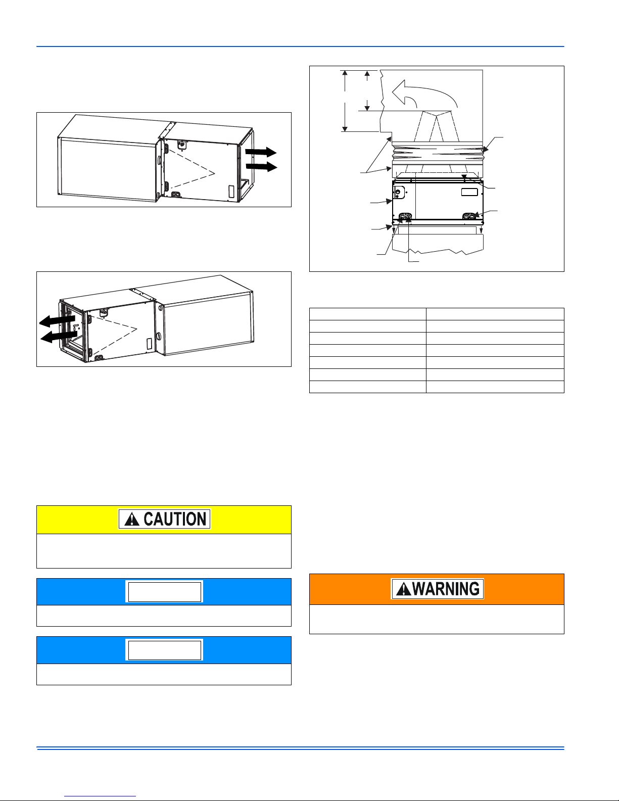
FIGURE 8: Horizontal Right Application
For horizontal left hand applications no conversion is required to an MC
coil when used with a downflow/horizontal furnace. A mounting plate,
supplied with every coil should always be installed on the side designated as top side. See Figure 8 & 9.
FIGURE 9: Horizontal Left Application
FURNACE ASSEMBLY - PC
These upflow coils are designed for installation on top of upflow furnaces only.
If the coil is used with a furnace of a different size, use a 45° transition
to allow proper air distribution through the coil.
1. Position the coil casing over the furnace opening as shown in Figure 10.
2. Place the ductwork over the coil casing flange and secure.
3. Check for air leakage between the furnace and coil casing and
seal appropriately.
Do not drill any holes or drive any screws into the front duct
flange on the coil in order to prevent damaging coil tubing (see
Figure 12).
FIGURE 10: Upflow Coil Installation
TABLE 5:
Dimension “C” should be at least 2/3 of dimension “D”. See Figure 12.
Coil Projection Dimensions - PC Coils
COIL SIZE DIMENSION “C” INCH
PC18 3-1/2
PC24 4-1/2
PC30, PC32, PC35 4-1/2
PC42, PC43, PC36, PC37 5-1/2
PC48 6-1/2
PC60 9
CRITICAL COIL PROJECTION
The coil assembly must be located in the duct such that a minimum distance is maintained between the top of the coil and the top of the duct.
Refer to Table 6.
SECTION V: DUCT CONNECTIONS
Air supply and return may be handled in one of several ways best
suited to the installation. Upflow, horizontal or downflow applications
may be used.
The vast majority of problems encountered with combination heating
and cooling systems can be linked to improperly designed or installed
duct systems. It is therefore highly important to the success of an installation that the duct system be properly designed and installed.
Use flexible duct collars to minimize the transmission of vibration/noise
into the conditioned space.
When installing this coil with an oil furnace, a minimum of six inches
clearance should be maintained from the top of the heat exchanger.
Refer to the heat pump add-on control instruction before installing
an add-on heat pump coil.
6
Use 1/2" screws to connect ductwork to unit. If pilot holes are
drilled, drill only through field duct and unit flange.
Page 7

841890-UIM-B-0612
NOTICE
NOTICE
Condensate
Deflector
S-Clips (3)
Vertical Drain Pan
NOTICE
S-Clips on Horizontal Pan
Feeder
Tubes
Condensate
Deflector
Condensate
Deflector
S-Clip
Drain Pan
Wall
Where return air duct is short, or where sound may to be a problem,
sound absorbing glass fiber should be used inside the duct. Insulation
of duct work is a must where it runs through an unheated space during
the heating season or through an uncooled space during the cooling
season. The use of a vapor barrier is recommended to prevent absorption of moisture from the surrounding air into the insulation. The supply
air duct should be properly sized by use of a transition to match unit
opening. All ducts should be suspended using flexible hangers and
never fastened directly to the structure. Duct work should be fabricated
and installed in accordance with local and/or national codes. This
includes the standards of the National Fire Protection Association for
Installation of Air-Conditioning and Ventilating Systems, NFPA No. 90B.
Equipment should never be operated without filters.
SECTION VI: CONDENSATE DRAIN
CONNECTIONS
All drain lines should be pitched away from unit drain pan and should be
no smaller than the coil drain connection.
Route the drain line so that it doesn’t interfere with accessibility to the
coil, furnace, air handling system or filter and will not be exposed to
freezing temperatures.
Instruct the owner that the evaporator coil drain pan should be
inspected and cleaned regularly to prevent odors and assure proper
drainage.
SUCTION FEEDER TUBECONDENSATE DEFLECTOR
Upflow or Downflow
No action required. See Figure 11.
FIGURE 11: Condensate Deflector on Vertical Drain Pan
Horizontal Left or Right
Use an appropriate tool to pry out water deflector with two or three sclips from the vertical drain pan. See Figure 11. Relocate the deflector
with s-clips on the Horizontal Drain Pan lined up to the coil support
bracket. See Figure 12. This positions the deflector below the feeder
tubes to channel the condensate to the drain pan.
When the coil is installed in an attic or above a finished ceiling, an
auxiliary drain pan must be provided under the coil as is specified
by most local building codes.
Coils should be installed level or pitched slightly toward the drain end.
Suggested pitch should not exceed 1/4-inch per foot of coil.
If the coil is provided with a secondary drain it should be piped to a location that will give the occupant a visual warning that the primary drain is
clogged. If the secondary drain is not used it must be capped.
Avoid Double Trapping.
Threaded drain connections should be hand tightened, plus
no more than 1 turn.
DO NOT
sealant may cause damage and premature failure of the drain pan.
use T e flonTM tape, “pipe dope”, or other sealants. The use of a
If the coil is installed in a draw-thru application (modular air handler), it is recommended to trap the primary and secondary drain
line. If the secondary drain line is not used, it must be capped.
The condensate deflector should be installed in the s-clip section
which is inside the drain pan edge. See Figure 13.
FIGURE 12: Condensate Deflector on Horizontal Drain Pan Edge
FIGURE 13: S-Clip Installation
7
Page 8

841890-UIM-B-0612
NOTICE
NOTICE
SECTION VII: REFRIGERANT LINE
CONNECTION
Coil is under inert gas pressure. Relieve pressure from coil by
removing rubber plug or by depressing schrader core.
Dry nitrogen should always be supplied through the tubing while it
is being brazed, because the temperature required is high enough
to cause oxidation of the copper unless an inert atmosphere is provided. The flow of dry nitrogen should continue until the joint has
cooled. Always use a pressure regulator and safety valve to insure
that only low pressure dry nitrogen is introduced into the tubing.
Only a small flow is necessary to displace air and prevent oxidation.
Connect lines as follows:
Route the refrigerant lines to the coil in a manner that will not
obstruct service access to the coil, air handling system, furnace flue
or filter.
1. Suction and liquid line connections are made outside the cabinet.
Leave the tubing connection panel attached to the cabinet with the
tubes protruding through it. Coil access panel should be removed
for brazing. The lines are expanded to receive the field line set
tubes.
2. Cut the end of the suction tube using a tube cutter. Place the tube
cutter as close as possible to the end of the tube to allow more
space for the connection and brazing of the suction line.
3. Remove the heat shield from the Customer Packet, soak in water,
and install over coil tubing to prevent overheating of cabinet.
4. Wrap a water soaked rag around the coil connection tubes inside
the cabinet to avoid damaging the TXV bulb.
5. Remove grommets where tubes exit the cabinet to prevent burning
them during brazing.
6. Purge refrigerant lines with dry nitrogen.
7. Braze the suction and liquid lines.
8. Remove the heat shield.
9. Re-attach the grommets to the lines carefully to prevent air leakage.
10. Attach the coil access panel to the cabinet.
Refer to Outdoor unit Installation Manual for evacuation, leak check and
charging instructions.
Lines should be sound isolated by using appropriate hangers or strapping.
All evaporator coil connections are copper-to-copper and should be
brazed with a phosphorous-copper alloy material such as Silfos-5 or
equivalent. DO NOT use soft solder.
SECTION VIII: COIL CLEANING
If the coil needs to be cleaned, it should be washed with Calgon CalClean (mix one part CalClean to seven parts water). Allow solution to
remain on coil for 30 minutes before rinsing with clean water. Solution
should not be permitted to come in contact with painted surfaces.
SECTION IX: AIR SYSTEM ADJUSTMENT
To check the CFM, measure the static pressure drop across the coil
using a portable manometer and static pressure tips. To prepare coil for
static pressure drop measurements - the system should have been
recently operational in cooling mode.
Table 7 below has WET coil data. Run system for approximately 15
minutes in cooling mode prior to taking measurements.
Drill 2 holes, one 3" after the coil (before any elbows in the ductwork)
and one 3” before the coil. Insert the pressure tips and read the pressure drop from the manometer. See Table 5 to determine the air flow,
and make the necessary adjustments to keep the CFM within the air
flow limitations of the coil.
TABLE 6:
Air Flow Data - St atic Pressure Drop
CFM @ Static Pressure Drop - IWG
Coil Size
0.10 0.15 0.20 0.25 0.30
18A 400 550 710 880 1000
18B 425 620 830 970 1125
24A 400 600 800 950 1075
24B 425 725 900 1075 1215
30A 425 600 800 950 1075
30B 450 725 900 1075 1215
32A 555 725 865 970 1080
35B 600 800 950 1090 1220
35C 792 1007 1206 1382 1572
36A 625 775 925 1025 1125
37A 689 880 1031 1180 1300
36B 825 976 1174 1300 1450
36C 975 1225 1375 1575 1775
42B 825 1000 1175 1325 1450
42C 1025 1275 1475 1650 1850
43C 785 1025 1210 1400 1570
48C 900 1075 1300 1475 1600
48D 1008 1224 1451 1620 1788
60D 1160 1432 1598 1750 1870
62D 1240 1532 1709 1870 2000
64D 1152 1362 1573 1783 1994
(Based on wet coil)
8
Page 9

SECTION X: INSTALLATION VERIFICATION
Was the coil still under pressure when received?
Pull rubber plug
to check for
pressure one time.
Was the coil still under pressure when received?
Depress schrader
core to check for
pressure one time.
Is coil metering device installed correctly?
Was the correct TXV installed per the outdoor unit instructions?
Is the TXV Bulb positioned correctly?
Is Bulb Insulated?
Is Equalizer Line connected?
Secondary
Primary
3” Min.
Were the primary and secondary
drains trapped correctly?
Right Hand
Discharge
Left Hand
Discharge
Trapped
Trapped
Horizontal Drain Conditions
(All other drain connections should be plugged)
Upflow Drain
Connections
Downflow Drain
Connections
Primary Drain
Alternate Drain
Were all drains trapped or plugged?
Trap Appropriate Side
(All other drain connections should be plugged)
Furnace
Furnace
Furnace
Furnace
Primary Drain
Alternate Drain
FIGURE 14: Pressure Check
841890-UIM-B-0612
FIGURE 15: TXV Check List
FIGURE 16: Drain Traps
FIGURE 17: Location of Trapped and Plugged Drain Connections
9
Page 10

NOTES
Subject to change without notice. Published in U.S.A. 841890-UIM-B-0612
Copyright © 2012 by Johnson Controls, Inc. All rights reserved. Supersedes: 841890-UIM-A-0412
York International Corp.
5005 York Drive
Norman, OK 73069
 Loading...