

York GM8S Series, LM8S Series, LY8S Series, GY8S*UH Series, GM8S*UH Series User's Information, Maintenance And Service Manual
...Page 1
USER’S INFORMATION,
EFFICIENCY
RATING
CERTIFIED
ISO 9001
Certified Quality
Management System
MAINTENANCE AND
SERVICE MANUAL
HIGH EFFICIENCY
TUBULAR HEAT EXCHANGER SERIES
MODELS:
GY8S*UH/GM8S*UH/GR8S/LY8S*UH/LM8S*UH/LF8*UH
(Single Stage Upflow / Horizontal / LowNOx)
CONTACT INFORMATION . . . . . . . . . . . . . . . . . . . . . . . . . . . . . . .1
TABLE OF CONTENTS
USER’S INFORMATION . . . . . . . . . . . . . . . . . . . . . . . . . . . . . . . . . . . 1
SAFETY . . . . . . . . . . . . . . . . . . . . . . . . . . . . . . . . . . . . . . . . . . . . . . 1
INSTRUCTIONS FOR EXAMINING THE
FURNACE INSTALLATION . . . . . . . . . . . . . . . . . . . . . . . . . . . . . . . 2
HOW YOUR GAS FURNACE WORKS . . . . . . . . . . . . . . . . . . . . . . 3
START-UP AND SHUTDOWN INSTRUCTIONS . . . . . . . . . . . . . . . 3
Read the Instructions Below Before Trying to Start the Furnace . . 3
Operating Instructions: . . . . . . . . . . . . . . . . . . . . . . . . . . . . . . . . . . 3
To Turn Off the Appliance: . . . . . . . . . . . . . . . . . . . . . . . . . . . . . . . 3
FURNACE USER MAINTENANCE . . . . . . . . . . . . . . . . . . . . . . . . .4
Air Filters . . . . . . . . . . . . . . . . . . . . . . . . . . . . . . . . . . . . . . . . . . . . 4
Removing Filters . . . . . . . . . . . . . . . . . . . . . . . . . . . . . . . . . . . . . .4
Blower Care . . . . . . . . . . . . . . . . . . . . . . . . . . . . . . . . . . . . . . . . . . 5
Motor Lubrication . . . . . . . . . . . . . . . . . . . . . . . . . . . . . . . . . . . . . . 5
SERVICE AND MAINTENANCE MANUAL . . . . . . . . . . . . . . . . . . . . 5
CONTACT INFORMATION
• Go to website at www.york.com click on “contact”, then click on “contact form” and follow the instructions.
• Contact us by mail:
York International
Consumer Relations
Norman, OK 73069
SAFETY SECTION . . . . . . . . . . . . . . . . . . . . . . . . . . . . . . . . . . . . . .5
FURNACE MAINTENANCE SECTION . . . . . . . . . . . . . . . . . . . . . . .5
FURNACE CLEANING SECTION . . . . . . . . . . . . . . . . . . . . . . . . . . .5
Burner Removal/Cleaning . . . . . . . . . . . . . . . . . . . . . . . . . . . . . . .5
Cleaning the Heat Exchanger . . . . . . . . . . . . . . . . . . . . . . . . . . . .5
SEQUENCE OF OPERATION . . . . . . . . . . . . . . . . . . . . . . . . . . . . .6
Continuous Blower . . . . . . . . . . . . . . . . . . . . . . . . . . . . . . . . . . . . .6
Intermittent Blower - Cooling . . . . . . . . . . . . . . . . . . . . . . . . . . . . .6
Heating Cycle . . . . . . . . . . . . . . . . . . . . . . . . . . . . . . . . . . . . . . . . .6
Hot Surface Ignition System . . . . . . . . . . . . . . . . . . . . . . . . . . . . . .7
TROUBLESHOOTING . . . . . . . . . . . . . . . . . . . . . . . . . . . . . . . . . . .7
FURNACE CONTROL DIAGNOSTICS . . . . . . . . . . . . . . . . . . . . . . .7
DIAGNOSTIC FAULT CODE STORAGE AND RETRIEVAL . . . . . .8
REPLACEMENT PARTS LIST . . . . . . . . . . . . . . . . . . . . . . . . . . . . . .9
REPLACEMENT PART CONTACT INFORMATION . . . . . . . . . . . . .10
WIRING DIAGRAM . . . . . . . . . . . . . . . . . . . . . . . . . . . . . . . . . . . . . .11
5005 York Drive
The manufacturer recommends that the user read all sections of this manual and keep the manual for future reference.
FIRE OR EXPLOSION HAZARD - Failure to follow safety
warnings exactly could result in serious injury, death, or property damage.
— Do not store or use gasoline or other flammable
vapors and liquids in the vicinity of this or any other
appliance.
— WHAT TO DO IF YOU SMELL GAS:
• Do not try to light any appliance.
• Do not touch any electrical switch; do not use any phone
(including cell phone) in your building.
• Leave the building immedia te l y.
• Immediately call your gas supplier from a neighbor’s
phone. Follow the gas supplier’s instructions.
• If you cannot reach your gas supplier, call the fire department.
— Installation and service must be performed by a quali-
fied installer, service agency or the gas supplier.
SECTION I: USER’S INFORMATION
SAFETY
1. The furnace area must be kept clear and free of combustible materials, gasoline and other flammable vapors and liquids.
2. Insulating materials may be combustible. The furnace must be
kept free and clear of insulating materials. The furnace area must
be examined when installed in an attic or other insulated space or
when insulation is added to be sure that the insulation material has
been kept away from the furnace.
3. The furnace needs air for combustion in order to operate properly
and safely. Do not block or obstruct air openings on the furnace,
air openings to the area where the furnace is installed, or spaces
around the furnace.
4. Follow the instructions exactly as shown on the OPERATING
INSTRUCTION LABEL or the Start-up and Shutdown Instructions
on Page 3 of this manual when lighting the furnace or turning the
furnace off.
5. Should the gas supply fail to shut off or if overheating occurs, shut
off the gas valve to the furnace before shutting off the electrical
supply.
6. Do not use this furnace if any part has been under water. A flooddamaged furnace is extremely dangerous. Attempts to use the furnace can result in fire or explosion. A qualified service agency
should be contacted to inspect the furnace and replace all gas
controls, control system parts, electrical parts that have been wet
or the furnace if deemed necessary.
268893-UUM-A-0407
Page 2
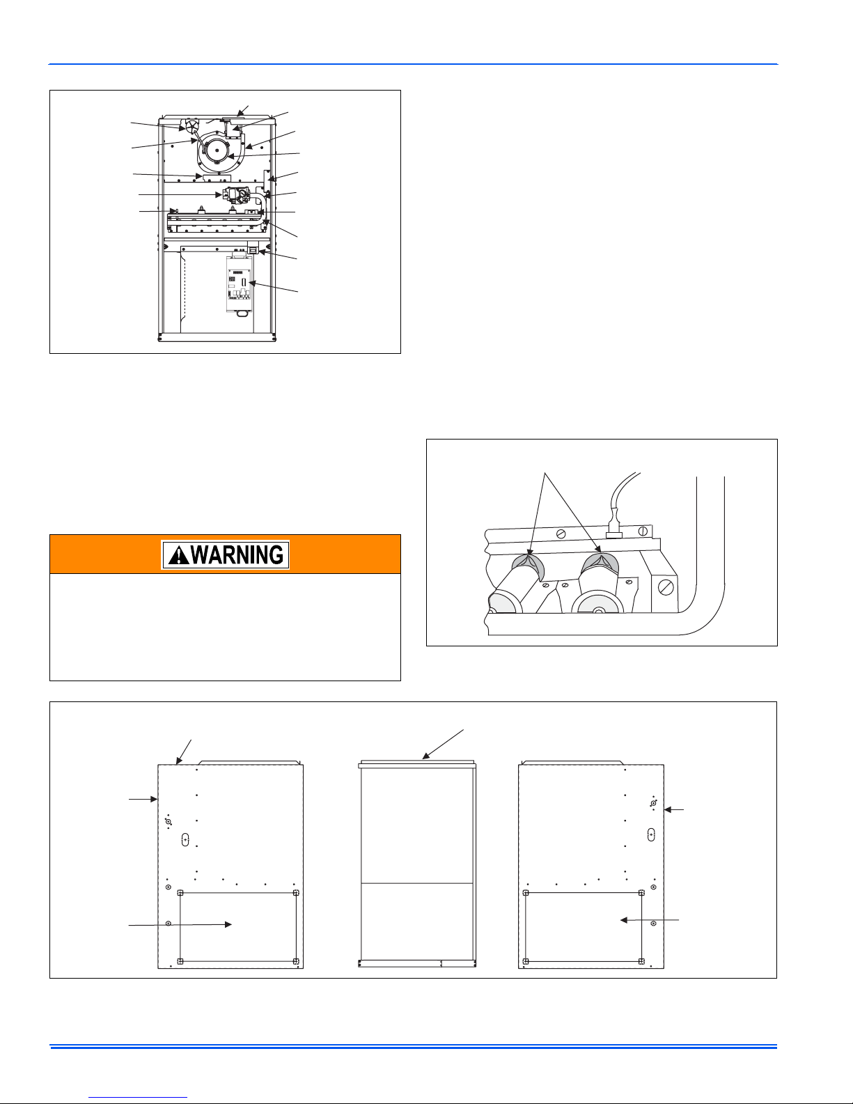
268893-UUM-A-0407
PRESUURE
SWITCH
SILICONE
TUBE
INDUCER
SHIELD
GAS VALVE
FLAME
SENSOR
VENT PIPE
FLUE
COLLAR
INDUCED DRAFT
ASSEMBLY
INDUCED DRAFT
MOTOR
ELECTRICAL
JUNCTION BOX
LIMIT
SWITCH
IGNITOR
MANIFOLD
PIPE
SAFETY SHUTOFF
SWITCH
CONTROL
BOARD
FIGURE 1: Component Locations
7. NEVER . . .Store flammable materials of any kind near your furnace. Gasoline, solvents, and other volatile liquids should be
stored only in approved containers outside your home. These
materials vaporize easily and are extremely dangerous.
8. NEVER . . .Store cleaning materials near your furnace. Materials
such as bleaches, detergents, powdered cleansers, etc., can
cause corrosion of the heat exchangers.
9. NEVER . . . Use the area around your furnace as a storage area
for items which could block the normal flow of air. This flow of air is
required for ventilation of the various furnace components.
INSTRUCTIONS FOR EXAMINING THE FURNACE
INSTALLATION
It is the owner’s responsibility to ensure that an annual inspection of the
entire heating portion of the unit is made by a qualified service agency.
Examine the furnace as outlined below in steps “1 - 6” before each
heating season. Use Figure 3 for visual reference.
1. Examine the heat exchanger, vent pipe, combustion air passes
gas, vent connectors and chimney to be sure they are clear and
free of obstructions.
2. Examine the vent pipe making sure it is firmly in place, that it
slopes slightly upward and is physically sound without holes and
all of the connections are secure.
3. Examine the return-air duct connections to make sure they are
physically sound, sealed to the furnace casing, and the ducts terminate outside the space containing the furnace.
4. Examine the furnace casing making sure the physical support is
sound without sagging, cracks or gaps. Examine the furnace base
making sure it is physically sound without cracks, gaps or sagging
and has a good seal.
5. Examine the furnace casing for obvious signs of deterioration.
6. Examine the burner flames to make sure they are in good adjustment. Refer to the pictorial sketch shown in Figure 2 as a comparison to the actual flame.
BLUE CONE PORTION OF FLAME SHOULD
ENTER HEAT EXCHANGER TUBE
FIRE OR EXPLOSION HAZARD
This furnace is designed and approved for use with Nat-
ural Gas and (LP) Propane Gas ONLY. DO NOT BURN
ANY LIQUID FUEL OR SOLID FUEL IN THIS FURNACE.
Burning any unapproved fuel will result in damage to the
furnace heat exchanger, which could result in Fire, Personal Injury, and/or Property Damage.
EXAMINE ENTIRE
5
FURNACE CASING
SHOWN IN ALL
DRAWINGS
6
REMOVE
PANEL
TO EXAMINE
BURNER
FLAMES
3
EXAMINE
RETURN AIR
DUCT
CONNECTION
EXAMINE EXTERNAL
VENT PIPE
4
EXAMINE
FURNACE
CASING
FIGURE 2: Burner Flame Drawing
1
EXTERNAL HEAT EXCHANGER INTERNAL
VENT COMBUSTION AIR PIPE. MUST
REMOVE PANEL TO EXAMINE.
4
EXAMINE
FURNACE
CASING
6
REMOVE
PANEL
TO EXAMINE
BURNER
FLAMES
3
EXAMINE
RETURN AIR
DUCT
CONNECTION
(side or bottom)
FIGURE 3: Furnace Examination Checkpoints
2 Unitary Products Group
Page 3
268893-UUM-A-0407
HOW YOUR GAS FURNACE WORKS
Your furnace is a very easy appliance to take for granted. Season after
season, it sits there in your home, keeping you warm and comfortable.
For this reason, you may never have given much thought to the way
your furnace operates. In order to get the safest and most efficient operation from your furnace, you should understand how your furnace does
its job.
When you set your thermostat to provide more heat in your home, you
are starting the heating cycle of the furnace. First, the inducer motor
starts to purge the heat exchanger of any remaining gases. Next, the
hot surface ignitor glows and after a warm-up period the gas valve
opens and ignition occurs. A short time later, the blower starts and distributes the warm air throughout the home. When the temperature setting on your thermostat is reached, the gas valve closes, the main
burners are turned off, and the blower continues to run until the remaining warm air in the system is distributed. When the blower stops, the
heating cycle has ended.
START-UP AND SHUTDOWN INSTRUCTIONS
Read the Instructions Below Before Trying to Start the
Furnace
If you do not follow these instructions exactly, a fire or
explosion may result causing property damage, personal
injury, and/or loss of life.
A. This appliance does not have a pilot. It is equipped with an ignition
device which automatically lights the burner. Do not try to light the
burner by hand.
B. BEFORE OPERATING; smell all around the appliance area for
gas. Be sure to smell next to the floor because some gas is
heavier than air and will settle on the floor.
C. Use only your hand to push the gas control switch to the “on” posi-
tion. Never use tools. If the switch will not operate by hand, don’t
try to repair it, call a qualified service technician. Force or
attempted repair may result in a fire or explosion.
D. Do not use this appliance if any part has been under water. Imme-
diately call a qualified service technician to inspect the appliance
and to replace any part of the control system and any gas control,
which has been under water.
Operating Instructions:
1. STOP! Read the safety information above.
2. Set the thermostat to the lowest setting.
3. Turn off all electric power to the appliance.
4. Remove furnace door.
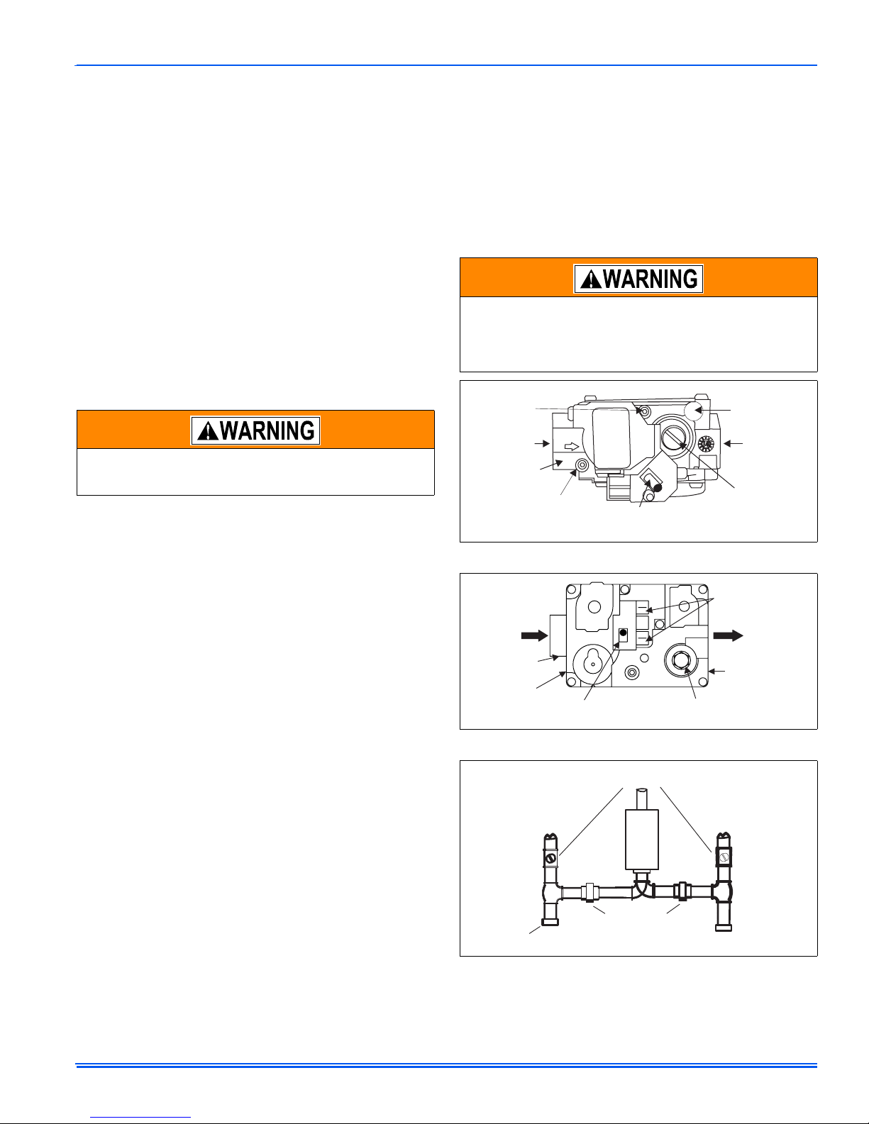
5. Move gas control switch to the “OFF” position. Do not force. See
Figures 4 or 5.
6. Wait five (5) minutes to clear out any gas. If you then smell gas,
STOP! Follow “B” in the safety information above. If you don’t
smell gas, go to next step.
7. Move gas control switch to the “ON” position. Do not force. See
Figures 4 or 5.
8. Replace burner access panel.
9. Turn on all electric power to the appliance.
10. Set thermostat to the desired setting. Burner will light, which may
take 30-60 seconds.
11. After three (3) trials for ignition, if the appliance will not operate follow the instructions, “TO TURN OFF THE APPLIANCE” and call
your service technician or gas supplier.
To Turn Off the Appliance:
1. Set the thermostat to lowest setting.
2. Turn off all electric power to the appliance if service is to be performed.
3. Remove burner access panel.
4. Move gas control switch to the “OFF” position. See Figures 4 or 5.
5. Replace burner access panel.
Should overheating occur, or the gas valve fail to shut off,
turn the external manual gas valve in the gas supply line to
the furnace to the “off” position and let the furnace cool off
before shutting off the electrical power supply. Refer to
Figure 6 or 7.
OUTLET
PRESSURE
PORT
INLET
WRENCH
BOSS
INLET
PRESSURE
PORT
ON/OFF SWITCH
(Shown in ON position)
OFF
ON
FIGURE 4: Gas Valve - All Except GR Models
INLET
WRENCH
BOSS
SUPPLY
PRESSURE
TAP
ON/OFF SWITCH
(shown in OFF position)
O
F
F
ON
MAIN REGULATOR
ADJUSTMENT
FIGURE 5: Gas Valve - GR Models Only
EXTERNAL MANUAL
SHUTOFF VALVE
TO GAS
SUPPLY
DRIP
LEG
GROUNDED JOINT UNION
MAY BE INSTALLED
INSIDE OR OUTSIDE UNIT.
FIGURE 6: Upflow Gas Piping
VENT PORT
OUTLET
MAIN REGULATOR
ADJUSTMENT
ELECTRICAL
CONNECTIONS
OUTLET
OUTLET
(MANIFOLD)
PRESSURE
TAP
TO GAS
SUPPLY
Unitary Products Group 3
Page 4
268893-UUM-A-0407
MANUAL
SHUT-OFF
VALV E
DRIP
GAS
PIPE
GAS
LEG
GAS BURNERS
GAS VALVE
PIPE
DRIP
LEG
MANUAL
SHUT-OFF VALVE
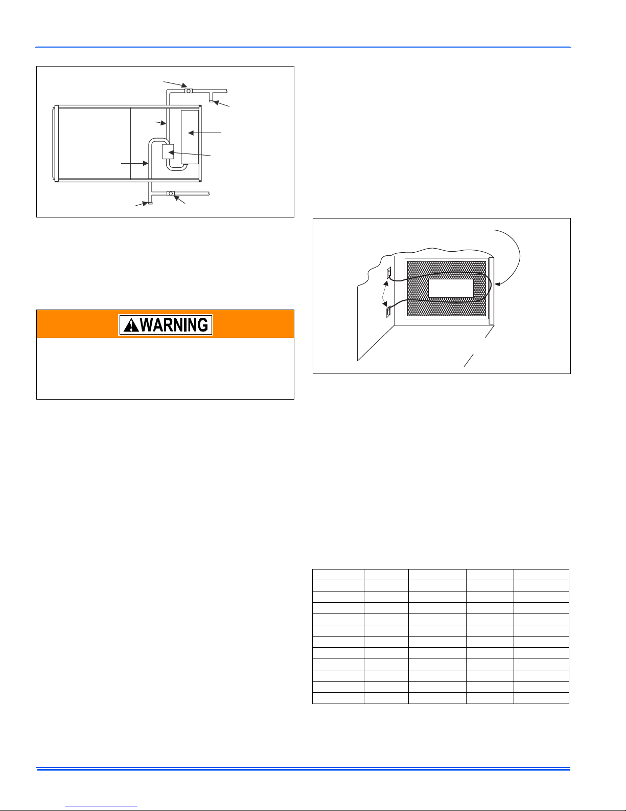
FIGURE 7: Horizontal Gas Piping
NOTE: The spring-loaded safety cut-off switch, mounted under the
blower deck will automatically cut off the electrical power supply
to the furnace when the blower panel is removed. As a safety
precaution, all electrical power and the gas supply to the furnace
should be turned off before servicing.
FURNACE USER MAINTENANCE
Before proceeding, be sure the area is well ventilated. Turn
the thermostat OFF. If the blower is running, wait until it
stops automatically. Turn OFF the gas and electrical power
supplies to the furnace. Check all metal parts and surfaces
to be sure they have cooled to room temperature before
you begin.
Every time the filters are changed the following items should be visually
inspected:
• Check combustion air and vent pipe for blockage or leakage.
• Check all components to be sure they are in good condition and
that there are no obvious signs of deterioration.
• Check the drain lines to make sure there are no cracks or leaks.
• Check for dirt or lint on any surfaces or on components. Do not try
to clean any of the surfaces or components. Cleaning of the furnace and its components must be done by a qualified service professional.
If during the inspection of your furnace, you find any of the following
conditions:
• Excessive amounts of dust and lint on components.
• Damaged or deteriorated components or surfaces.
• Leaks or blockage in the vent pipe passages.
• Water on any surface inside or outside of the furnace.
Do not operate the furnace, call a certified dealer / servicing contractor
to check and / or clean your furnace, or for more information if you have
questions about the operation of your furnace.
If all components appear to be in good operating condition, replace the
front panels. Turn ON the gas and electrical power supplies to the furnace, and set thermostat to the desired temperature.
Air Filters
Dirty filters greatly restrict the flow of air and may cause damage to the
moving parts of the furnace. If the filters become clogged the heat
exchangers and blower motor could overheat resulting in a potentially
dangerous situation. The filters should be checked every 3 months. On
new construction, check the filters every week for the first four weeks
and every three weeks after that, especially if the indoor fan is running
continuously. When replacing the filter(s) you must use filters that are
the same size as those recommended in Table 1. Never operate your
furnace without a suitable air filter.
Removing Filters
Internally Mounted Air Filters
Some upflow furnaces may have their filters located on the side or bottom of the furnace in a filter wire retainer located inside the blower compartment. To check filters located in the blower compartment:
1. Remove the upper furnace door by lifting up. Pull out bottom of
door and lower from furnace.
2. Remove the blower compartment panel by lifting up.
3. The filters will be located on the bottom or on one of the sides. To
remove bottom-mounted or side mounted filter (s) on all furnaces,
push the looped end of the filter retainer rod in, and then move the
retainer rod away from the filter.
4. Reverse the procedure to reinstall filters.
POSITION WIRE RETAINER
PROVIDED UNDER FLANGE
CLIPS
RIGHT SIDE
INSTALLATION
SHOWN
FIGURE 8: Internal Filter Retainer
Externally Mounted Air Filters
The air filter should be located in a rack attached to the casing of the
furnace or placed in the return air duct. You can gain access to the filter
by pulling on the door or unscrewing the retaining screw, then slide the
filter(s) out of its channel. Replace throw away filter(s) with the same
size new filter(s). Throw away filter(s) may be replaced with cleanable
filter(s) at this time. Cleanable filter(s) may be cleaned as described in
the manufacturer instructions or as described below and then reinstalled.
To replace the filter after cleaning you must do the following:
1. Slide filter into place.
2. Snap the door on or place the door in position and tighten the
retaining screws, if provided.
3. Make sure the door is secure to the end of the filter rack.
TABLE 1:
Cabinet Size Side (in) Side (cm) Bottom (in) Bottom (cm)
Filter Sizes
A 16 x 25 40.6 x 63.5 14 x 25 35.6 x 63.5
A 16 x 25 40.6 x 63.5 14 x 25 35.6 x 63.5
A 16 x 25 40.6 x 63.5 14 x 25 35.6 x 63.5
B 16 x 25 40.6 x 63.5 16 x 25 40.6 x 63.5
C (2) 16 x 25 (2) 40.6 x 63.5 20 x 25 50.8 x 63.5
B 16 x 25 40.6 x 63.5 16 x 25 40.6 x 63.5
B 16 x 25 40.6 x 63.5 16 x 25 40.6 x 63.5
C (2) 16 x 25 (2) 40.6 x 63.5 20 x 25 50.8 x 63.5
C 16 x 25 40.6 x 63.5 20 x 25 50.8 x 63.5
C (2) 16 x 25 (2) 40.6 x 63.5 20 x 25 50.8 x 63.5
D (2) 16 x 25 (2) 40.6 x 63.5 22 x 25 55.9 x 63.5
How to Clean your Filter
High-velocity filters may be cleaned with a vacuum cleaner or washed
with a garden hose. Be sure to shake off excess water and allow filter to
completely dry before re-installing the filter.
FURNACE
FRONT
4 Unitary Products Group
Page 5
268893-UUM-A-0407
Blower Care
Even with good filters properly in place, blower wheels and motors will
become dust laden after long months of operation. The entire blower
assembly should be inspected annually. If the motor and wheel are
heavily coated with dust, they can be brushed and cleaned with a vacuum cleaner. If the blower cannot be properly cleaned without removing
it from the furnace, then this service must be performed by a qualified
service agency.
Make sure you DO NOT move the clip on weight on the
indoor fan wheel when cleaning the wheel. This weight is
used to balance the wheel. Moving the weight will cause
the fan wheel to vibrate.
Motor Lubrication
The motors in these furnaces are permanently lubricated, and do not
require periodic oiling.
Every time the filters are changed, the following items should be visually inspected:
• Check combustion air and vent pipe for blockage or leakage.
• Check all components to be sure they are in good condition and
that there are no obvious signs of deterioration.
• Check the drain lines to make sure there are no cracks or leaks.
• Check for dirt or lint on any surfaces or on components. Do not try
to clean any of the surfaces or components. Cleaning of the furnace and its components must be done by a qualified service professional.
If during the inspection of your furnace, you find any of the following
conditions:
• Excessive amounts of dust and lint on components.
• Damaged or deteriorated components or surfaces.
• Leaks or blockage in the vent pipe passages.
• Water on any surface inside or outside of the furnace.
Do not operate the furnace, call a certified dealer / servicing contractor
to check and / or clean your furnace, or for more information if you have
questions about the operation of your furnace.
If all components appear to be in good operating condition, replace the
front panels. Turn ON the gas and electrical power supplies to the furnace, and set thermostat to the desired temperature.
SECTION II: SERVICE AND MAIN TENANCE
MANUAL
SAFETY SECTION
The following safety rules must be followed when servicing th e
furnace.
ELECTRIC SHOCK, FIRE OR EXPLOSION HAZARD
Failure to follow safety warnings exactly could result in
dangerous operation, serious injury, death or property
damage.
Improper servicing could result in dangerous operation,
serious injury, and death or property damage.
• Before servicing, disconnect all electrical power to the furnace.
• When servicing controls, label all wires prior to disconnecting. Reconnect wires correctly.
• Verify proper operation after servicing.
FURNACE MAINTENANCE SECTION
The furnace should be cleaned and adjusted by a certified dealer or
qualified service contractor once a year or before the start of every
heating season. The following items must be cleaned and serviced or
replaced if there are signs of deterioration.
1. The vent terminal.
2. The furnace vent and combustion air intake passageways. Should
it be necessary to service the vent/air intake system, the manufacturer recommends this service be conducted by a qualified service
agency. The operation of this appliance requires the reassembly
and resealing of the vent/air intake system.
3. The furnace burners, ignitor and flame sensor.
4. The condensate collection and disposal system. If any disassembly of components containing flue or vent gases is required, a
qualified service agency must perform the service.
FURNACE CLEANING SECTION
NOTE: The cleaning operations listed below must be performed only by
a qualified service agency.
Burner Removal/Cleaning
The main burners should be checked periodically for dirt accumulation.
If cleaning is required, follow this procedure:
1. Turn off the electrical power to the unit.
2. Turn off the gas supply at the external manual shut-off valve and
loosen the ground union joint.
3. Remove the upper access panel and remove the burner box
cover.
4. Disconnect wires from flame sensor, rollout switch and HSI igniter.
Remove igniter carefully, as it is easily broken.
5. Remove the screws that hold the burner box assembly to the vest
panel and remove the assembly.
6. Remove burners from the burner assembly.
7. Burners may be cleaned by rinsing in hot water.
8. Reassemble the burners in the reverse order.
Cleaning the Heat Exchanger
Lower Heat Exchanger Access
1. Turn off the electrical power to the unit and turn off gas supply at
the shutoff valve.
2. Remove the blower and burner compartment access doors. Disconnect the gas supply piping at the union to permit removal of the
entire burner and gas control assembly from the vestibule panel.
Use the wrench boss on the gas valve when removing or installing
this piping. See Figure 4 or 5.
3. Unplug the igniter from the wire harness. Disconnect sensor and
rollout switch wires located on top of the air shield. Identify and
note the location of all leads for ease of reinstallation. Also disconnect the wires at the side rollout switches (upflow only) and the
gas valve wires.
4. Remove the screws holding the burner assembly to the vestibule
panel and remove this assembly. Handle the assembly carefully
since it contains the igniter, which is fragile and easily broken. The
lower portion of the heat exchanger will now be exposed. To clean
the burner assembly, use a vacuum cleaner, or remove the burners as outlined in burner cleaning, and clean in hot water.
Upper Heat Exchanger Access
1. Perform steps 1-4 above.
2. Disconnect vent piping from the vent motor assembly at the top
panel on the furnace (upflow only). On downflow models, the vent
pipe is secured to the vent motor outlet with a screw. Remove this
screw before proceeding.
Unitary Products Group 5
Page 6
268893-UUM-A-0407
3. Unplug the vent motor wires and ground wire. Remove the pressure switch tubing at the top on the vent motor housing.
NOTE: It is recommended that replacement gaskets be available
before removing vent motor.
4. Remove six mounting screws that hold the vent motor to the
restrictor plate. The surface is gasketed and the gasket can be
reused if it is carefully removed. It is necessary to remove this
assembly to gain access to the restrictor plate mounting holes.
The assembly may be vacuumed if cleaning is necessary. If any
vent assembly parts are damaged, replace with an entire new
assembly (except for gaskets).
5. Remove the perimeter screws attaching the restrictor plate assembly to the vestibule panel. The surface is also gasketed. The
assembly, including the flue baffle plate (rear) may be vacuumed
or cleaned with hot water if necessary.
6. The upper portion of the heat exchanger is now accessible. With a
long flexible wire brush, clean inside each tube at both the top and
bottom. The brush must pass around the rear heat exchanger
tubes. Vacuum loose scale and dirt from each tube.
7. Clean - Replace all components in reverse order. Re-gasket all
surfaces which required a gasket. Reconnect all wiring. Reattach
vent pipe and gas supply lines before restoring service to furnace.
Restore electrical power, check gas supply piping for leaks, and
then verify furnace operation.
Label all wires prior to disconnection when servicing
controls. Wiring errors can cause improper and dangerous operation. Verify proper operation after servicing.
SEQUENCE OF OPERATION
The following describes the sequence of operation of the furnace. Refer
to Figure 1 for component location.
Continuous Blower
Cooling/heating thermostats have a fan switch that has an ON and
AUTO position. In the ON position the thermostat circuit is completed
between terminals R and G. The motor will operate on the speed tap
wire that is connected to the “HI COOL” cooling terminal on the control
board. To obtain a constant air circulation at lower flow rate, change the
high-speed wire to either the medium speed wire or the low speed wire.
Intermittent Blower - Cooling
Cooling/heating thermostats have a fan switch that has an ON and
AUTO position. In the AUTO position the thermostat circuit is completed
between terminals R and G when there is a call for cooling. The motor
will operate on the speed tap wire that is connected to the “HI COOL”
cooling terminal on the control board. The fan off setting is fixed at 60
seconds to improve cooling efficiency.
Heating Cycle
When the thermostat switch is set on HEA T and the fan is set on AUT O,
and there is a call for heat, a circuit is completed between terminals R
and W of the thermostat. When the proper amount of combustion air is
being provided, the pressure switch will close, the ignition control provides a 17-second warm-up period, the gas valve then opens, the gas
starts to flow, ignition occurs and the flame sensor begins its sensing
function. The blower motor will energize 30 seconds after the gas valve
opens, if a flame is detected. Normal furnace operation will continue
until the thermostat circuit between R and W is opened, which causes
the ignition system and gas valve to de-energize and the burner flames
to be extinguished. The vent motor will operate for 15 seconds and the
blower motor will operate for the amount of time set by the fan-off delay
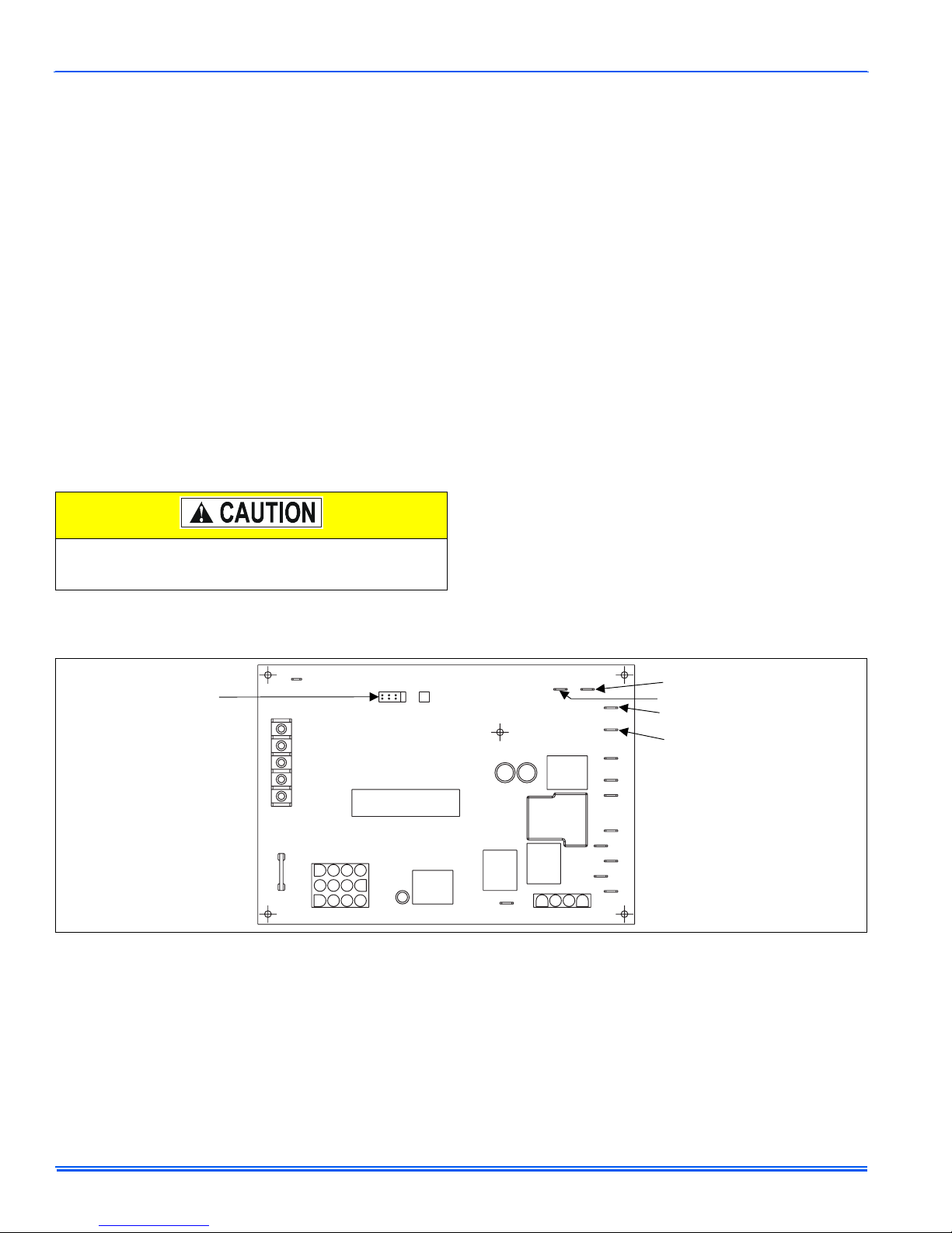
jumper located on the control board. See Figure 8. The heating cycle is
complete, and ready for the start of the next heating cycle.
TWIN
FAN OFF
ADJUSTMENT
JUMPER
Y/Y2
W
R
G
C
120
180
90
60
BLOWER
OFF
DELAY
FIGURE 9: Furnace Control Board
If the flame is not detected within 7 seconds of the gas valve opening,
the gas valve is shut off and a retry operation begins. If the flame is lost
for 2 seconds during the 10-second stabilization period, the gas valve is
shut off and a retry operation begins. During a retry operation, the vent
motor starts a 15 second inter-purge and the ignitor warm-up time is
extended to 27 seconds. If the flame is established for more than 10
seconds after ignition during a retry, the control will clear the ignition
attempt (retry) counter. If three retries occur during a call for heat, the
furnace will shut down for one hour. If at the end of the one hour shut
down there is a call for heat, the furnace will initiate a normal start cycle.
If the problem has not been corrected the furnace will again lockout
after three retries.
YELLOW-MED. LOW
RED-LOW
BLACK-HI
BLUE-MED. HI
HUM
PAR K
PARK
HI COOL
HEAT
EAC-H
L1
XFMR
NEUTRALS
A momentary loss of gas supply, flame blowout, or a faulty flame probe
circuit will result in a disruption in the flame and be sensed within 1.0
seconds. The gas valve will de-energize and the control will begin a
recycle operation. A normal ignition sequence will begin after a 15 second inter-purge. If during the five recycles the gas supply does not
return, or the fault condition is not corrected the ignition control will lockout for 60 minutes.
During burner operation, a momentary loss of power for 50 milliseconds
or longer will de-energize the gas valve. When the power is restored,
the gas valve will remain de-energized and the ignition sequence will
immediately restart.
6 Unitary Products Group
Page 7
268893-UUM-A-0407
Hot Surface Ignition System
HOT SURFACE IGNITION SYSTEM
Do not attempt to light this furnace by hand (with a
match or any other means). There may be a potential
shock hazard from the components of the hot surface
ignition system. The furnace can only be lit automatically
by its hot surface ignition system.
TROUBLESHOOTING
The following visual checks should be made before troubleshooting:
1. Check to see that the power to the furnace and the ignition control
module is ON.
2. The manual shut-off valves in the gas line to the furnace must be
open.
3. Make sure all wiring connections are secure.
4. Review the sequence of operation. Start the system by setting the
thermostat above the room temperature. Observe the system’s
response. Then use the troubleshooting section in this manual to
check the system’s operation.
Never bypass any safety control to allow furnace operation. To do so will allow furnace to operate under potentially hazardous conditions.
Do not try to repair controls. Replace defective controls
with UPG Source 1 Parts.
Never adjust pressure switch to allow furnace operation.
FURNACE CONTROL DIAGNOSTICS
The furnace has built-in, self-diagnostic capability. If a system problem
occurs, a blinking LED shows a fault code. The LED can flash red,
green or amber to indicate various conditions. It is located behind a
clear view port in the blower compartment door.
The control continuously monitors its own operation and the operation
of the system. If a failure occurs, the LED will indicate the failure code. If
the failure is internal to the control, the light will stay on continuously. In
this case, the entire control should be replaced, as the control is not
field repairable.
Flash sequence codes 1 through 11 are as follows: LED will turn “on”
for 1/4 second and “off” for 1/4 second. This pattern will be repeated the
number of times equal to the code. For example, six “on” flashes equals
a number 6 fault code. All flash code sequences are broken by a 2 second “off” period.
SLOW GREEN FLASH: Normal operation.
SLOW AMBER FLASH: Normal operation with call for heat.
RAPID RED FLASH: Twinning error, incorrect 24V phasing. Check
twinning wiring.
RAPID AMBER FLASH: Flame sense current is below 1.5 microamps.
Check and clean flame sensor. Check for proper gas flow. Verify that
current is greater than 1.5 microamps at flame current test pad.
4 AMBER FLASHES: The control board is recie ving a “Y” signal from
the thermostat without a “G” signal, indicating improper thermostat wiring.
1 RED FLASH: This indicates that flame was sensed when there was
not a call for heat. With this fault code the control will turn on both the
inducer motor and supply air blower. A gas valve that leaks through or
is slow closing would typically cause this fault.
2 RED FLASHES: This indicates that the normally open pressure
switch contacts are stuck in the closed position. The control confirms
these contacts are open at the beginning of each heat cycle. This would
indicate a faulty pressure switch or miswiring.
3 RED FLASHES: This indicates the normally open pressure switch
contact did not close after the inducer was energized. This could be
caused by a number of problems: faulty inducer, blocked vent pipe, broken pressure switch hose or faulty pressure switch.
4 RED FLASHES: This indicates that a primary or auxiliary limit switch
has opened its normally closed contacts. With this fault code the control
will operate the supply air blower and inducer. This condition may be
caused by: dirty filter, improperly sized duct system, incorrect blower
speed setting, incorrect firing rate or faulty blower motor.
5 RED FLASHES: This fault is indicated if the normally closed contacts
in the rollout switch opens. The rollout control is manually reset. If it has
opened, check for proper combustion air, proper inducer operation, and
primary heat exchanger failure or burner problem. Be sure to reset the
switch and cycle power (24 VAC) to the control after correcting the failure condition.
6 RED FLASHES: This indicates that after the unit was operating, the
pressure switch opened 4 times during the call for heat. If the main
blower is in a “Delay on” mode, it will complete it, and any subsequent
delay off period. The furnace will lock out for one hour and then restart.
7 RED FLASHES: This fault code indicates that the flame could not be
established. This no-light condition occurred 3 times (2 retries) during
the call for heat before locking out. Low gas pressure, faulty gas valve,
dirty or faulty flame sensor, faulty hot surface ignitor or burner problem
may cause this. The furnace will lock out for one hour and then restart.
8 RED FLASHES: This fault is indicated if the flame is lost 5 times (4
recycles) during the heating cycle. This could be caused by low gas
pressure, dirty or faulty flame sensor or faulty gas valve. The furnace
will lock out for one hour and then restart.
9 RED FLASHES: Indicates reversed line voltage polarity or grounding
problem. Both heating and cooling operations will be affected. Check
polarity at furnace and branch. Check furnace grounding. Check that
flame probe is not shorted to chassis.
10 RED FLASHES: Gas flow with no call for heat. Check gas valve and
gas valve wiring.
11 RED FLA SHES: This indicates that a primary or auxiliary limit switch
has opened its normally-closed contacts and has remained open for
more than five minutes. This condition is usually caused by a failed
blower motor or blower wheel. Cycle power (24 VAC) to the control to
reset the hard lockout condition after correcting the failure condition.
12 RED FLASHES: This code indicates an open igniter circuit, which
could be caused by a disconnected or loose wire or by a cracked or broken igniter.
STEADY ON RED: Control failure. Replace control board.
60-MINUTE AUTOMATIC RESET FROM LOCKOUT: This control
includes a “watchdog” type circuit that will reset from a lockout condition
after 60 minutes. Operational faults 6,7,8 will be reset. This provides
protection to an unoccupied structure if a temporary condition exists
causing a furnace malfunction. An example would be a low incoming
gas supply pressure preventing unit operation. When the gas pressure
is restored, at some point the “watchdog” would restart the unit and provide heat for the house.
NOTE: If a flame is detected the control flashes the LED for 1/8 of a
second and then enters a flame stabilization period.
IGNITION CONTROL
Normal flame sense current is approximately
3.7 microamps DC (µa)
Low flame signal warning starts at 1.5 microamps.
Low flame signal control lockout point is
0.1 microamps DC (µa)
Unitary Products Group 7
Page 8
268893-UUM-A-0407
DIAGNOSTIC FAULT CODE STORAGE AND
RETRIEVAL
The control in this furnace is equipped with memory that will store up to
five error codes to allow a service technician to diagnose problems
more easily. This memory will be retained even if power to the furnace
is lost. This feature should only be used by a qualified service tech-
nician.
The control stores up to five separate error codes. If more than five
error codes have occurred since the last reset, only the five most recent
will be retained. The furnace control board has a button, labeled "LAST
ERROR" that is used to retrieve error codes. This function will only work
if there are no active thermostat signals. So any call for heating, cooling
or continuous fan must be terminated before attempting to retrieve error
codes.
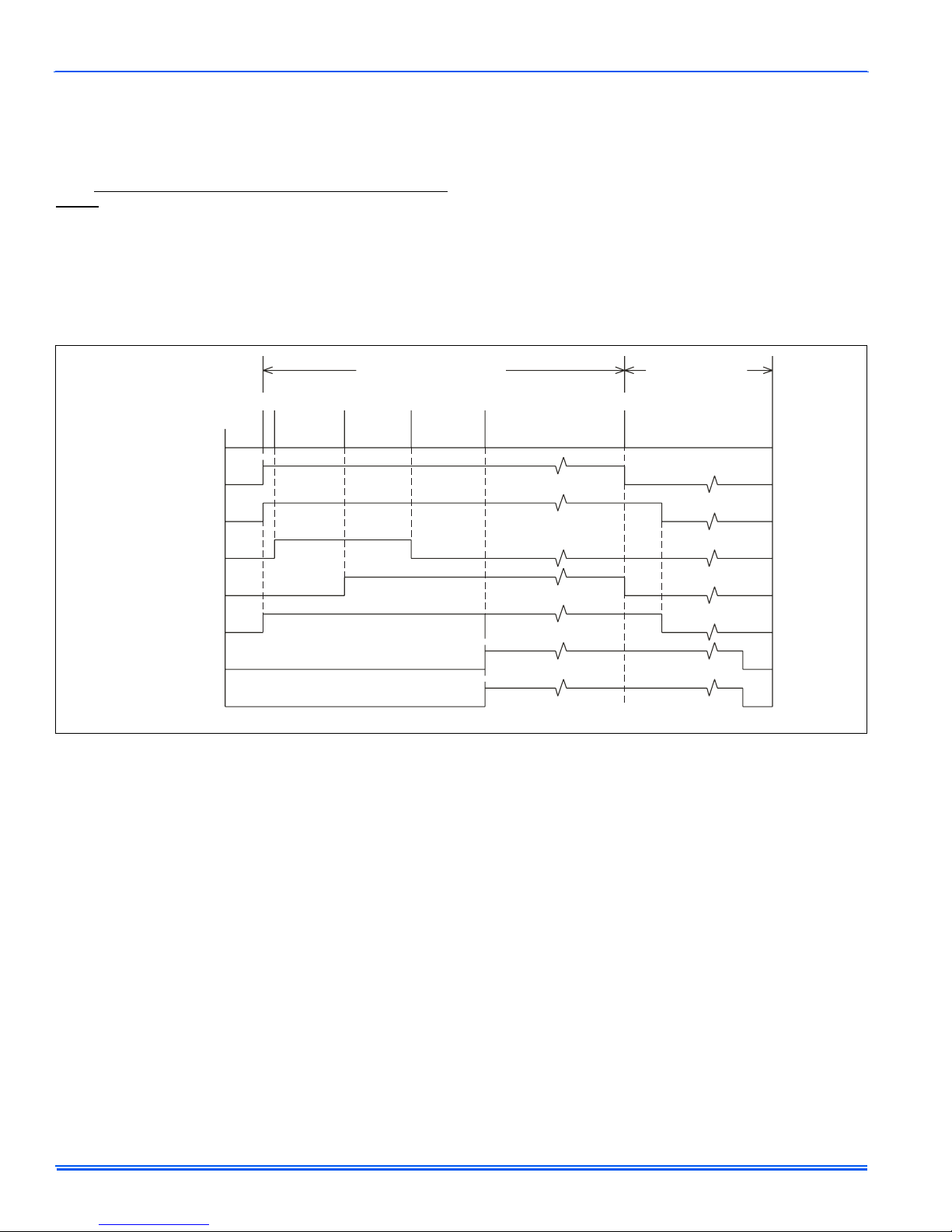
Thermostat Calling for Heat
(Seconds)
THERMOSTAT
INDUCER
IGNITOR
MAIN VALVE
HUMIDIFIER
ELECTRONIC
AIR CLEANER
CIRCULATING
BLOWER
OFF
OFF
OFF
OFF
OFF
OFF
OFF
0
2
ON
ON
ON
17 22
ON
Fan on Delay
30 Seconds
OFF
To retrieve the error codes, push the LAST ERROR button. The LED on
the control will then flash the error codes that are in memory, starting
with the most recent. There will be a two-second pause between each
flash code. After the error codes have all been displayed, the LED will
resume the normal slow green flash after a five second pause. To
repeat the series of error codes, push the button again.
If there are no error codes in memory, the LED will flash two green
flashes. To clear the memory, push the LAST ERROR button and hold it
for more than five seconds. The LED will flash three green flashes when
the memory has been cleared, then will resume the normal slow green
flash after a five-second pause.
Thermostat Satisfied
52
ON
OFF
ON
OFF
ON
OFF
0
OFF
15 Sec.
Post
Purge
OFF
OFF
60, 90, 120, 180 SEC.
Selectable Fan Off Delay
OFF
OFF
OFF
OFF
FIGURE 10: Furnace Control Event Schedule
8 Unitary Products Group
Page 9
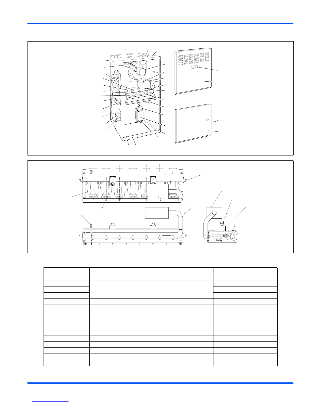
SECTION III: REPLACEMENT PARTS LIST
268893-UUM-A-0407
43
29
8
23
12
7
17
19
21
13
1
16
15
26
40
28
2
11
4
6,20
24
22
9
10
5
31
3
30
39
25
37
27
12A
11
19
12
24
TABLE 2:
7
Field Installed Accessories - Non Electrical
36
MODEL NO. DESCRIPTION USED WITH
1NP0347 PROPANE (LP) CONVERSION KIT ALL MODELS
1PS0301
1PS0302 80 MBH
1PS0311 100, 115, 130 MBH
1SR0302 SIDE RETURN FILTER KIT 1” FILTER ALL MODELS
1SR0200 SIDE RETURN FILTER KIT 1-4” FILTER ALL MODELS
1BR0114 BOTTOM RETURN FILTER KIT 1” FILTER 14-1/2” CABINETS
1BR0214 BOTTOM RETURN FILTER KIT 1-4” FILTER 14-1/2” CABINETS
1BR0117 BOTTOM RETURN FILTER KIT 1” FILTER 17-1/2” CABINETS
1BR0217 BOTTOM RETURN FILTER KIT 1-4” FILTER 17-1/2” CABINETS
1BR0121 BOTTOM RETURN FILTER KIT 1” FILTER 21” CABINETS
1BR0221 BOTTOM RETURN FILTER KIT 1-4” FILTER 21” CABINETS
1BR0124 BOTTOM RETURN FILTER KIT 1” FILTER 24-1/2” CABINETS
1BR0224 BOTTOM RETURN FILTER KIT 1-4” FILTER 24-1/2” CABINETS
1HF0801 INTERNAL FILTER KIT WITH 1” FIBER FILTER ALL MODELS
HIGH ALTITUDE PRESSURE SWITCH KIT
(Does Not Include Orifices)
35
40, 60 MBH
Unitary Products Group 9
Page 10
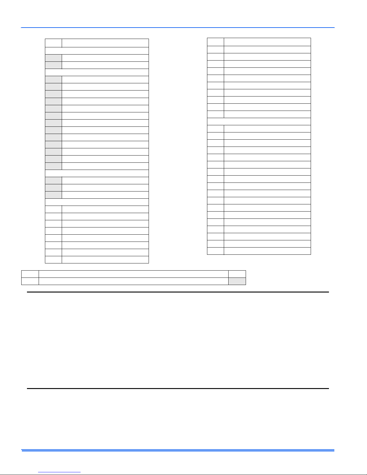
268893-UUM-A-0407
ITEM DESCRIPTION
MOTOR
MOTOR,DIRECT DRIVE BLOWER
1
2 MOTOR,VENTOR ASS’Y
ELECTRICAL
3 CAPACITOR
4 CONTROL, HIGH LIMIT
5 CONTROL, FURACE
6IGNITER
7 SENSOR, FLAME
8 SWITCH, AIR PRESSURE [1LP]
9 SWITCH, DOOR [SW]
10 TRANSFORMER
11 VALVE, GAS
12 CONTROL, LIMIT (Top)
CONTROL, LIMIT (Side, 2 Req’d)
12A
CONTROL, AUX LIMIT (2 Req’d)
13
14* FUSE
AIR MOVING
15 HOUSING, BLOWER
16 WHEEL, BLOWER
16A PANEL, FILLER WRAP
FABRICATED PARTS
17 SHIELD, SECONDARY AIR
18* BAFFLE, FLUE
19 BURNER, MAIN GAS
20 BRACKET, IGNITER
21 DECK, BLOWER (Rear)
22 DECK, FRONT
23 HEAT EXCHANGER ASS’Y
24 MANIFOLD, GAS
(Primary)
ITEM DESCRIPTION
25 PANEL, VEST ACCESS (Burner)
26 PAN, BASE
27 PANEL, BLOWER ACCESS
28 PANEL, TOP
29 WRAPPER, INSULATED
30 CHANNEL, TOE PLATE
31 BASE FRAME, SIDE (2 Req’d)
32* PLATE, RESTRICTOR
33* SHIELD, INDUCER
34 BRACKET, ROLL-OUT SWITCH
MISCELLANEOUS
35* FILTER
36* RACK, FILTER
37 PLUG HOLE WINDOW CLEAR-.875”
38 ORIFICE, BURNER
(Natural #45)
39 HANDLE, DOOR
40 COLLAR, FLUE
41* GROMMET, 1/2” DIA.
42* GASKET, RESTRICTOR PLATE
43 TUBING, SILICONE
44* SPRING, DOOR
45* WIRING DIAGRAM
46* WIRING HARNESS
47* FERRULE
48* GROMMET
49* BEZEL/LOGO
50* MOTOR MOUNT
51* LO-NOX SCREEN
52* GASKET KIT, INDUCER MOTOR
NOTE: *Not Shown
Major components and suggested stocking items are shown with shaded item number.
REPLACEMENT PART CONTACT INFORMATION
This is a generic parts list. To request a complete parts list, refer to the contact information below:
• Visit our website at www.source1parts.com for the following information:
1. Search for a part or browse the catalog.
2. Find a dealer or distributor.
3. Customer Service contact information.
a. Click on the “Brand Links” button
b. Click on the “Customer Service” button
• You can contact us by mail. Just send a written request to:
York International
Consumer Relations
5005 York Drive
Norman, OK 73069
10 Unitary Products Group
Page 11
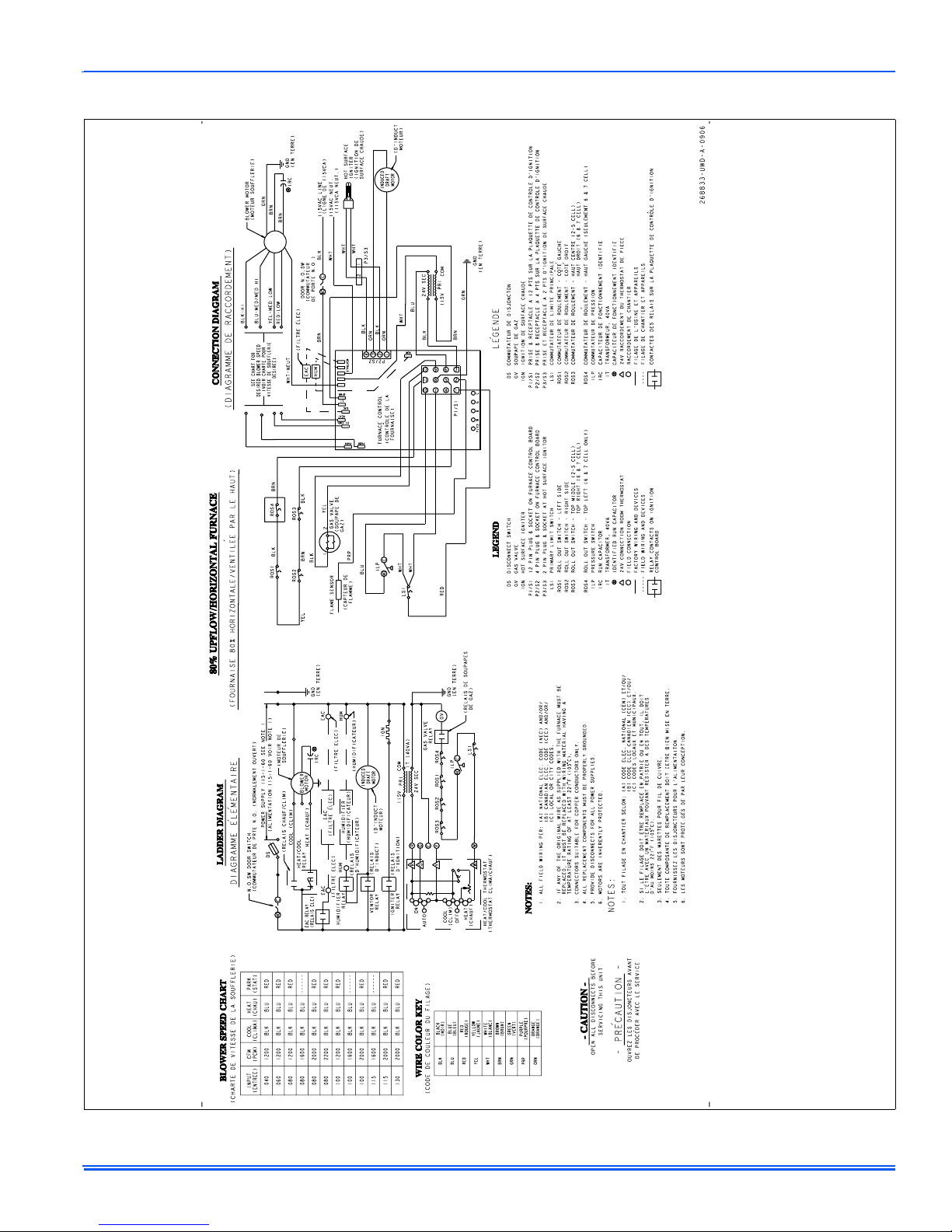
SECTION IV: WIRING DIAGRAM
268893-UUM-A-0407
FIGURE 11: Wiring Diagram
Unitary Products Group 11
Page 12
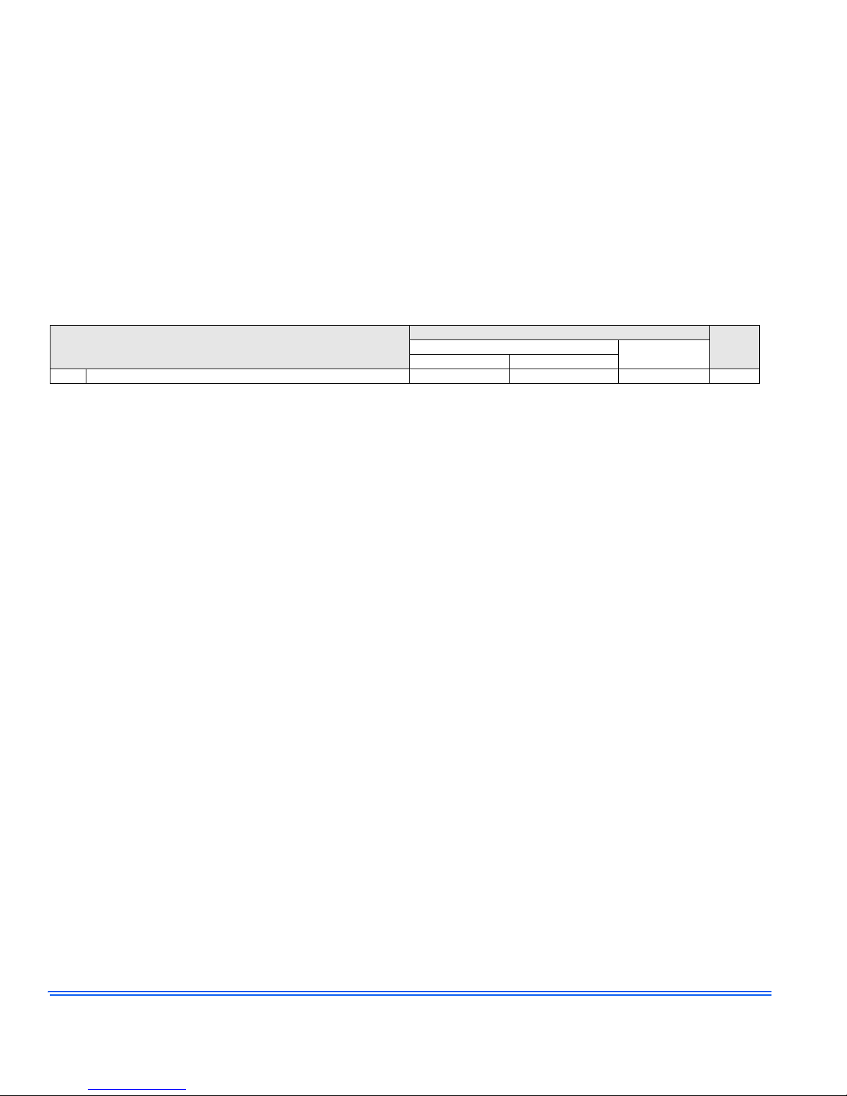
Limited Warranty
UPG warrants this product to be free from d efects in facto ry workmanshi p and material under nor mal use and ser vice and will , at its op tion, repair or replace
any parts that prove to have such defects accordin g to the ter ms out lined on this warran ty. This warranty covers only the eq uip ment described by the Product
Model Number and Serial Number listed on the Warranty Registration Card.
UPG warrants the primary heat excha ngers i n th e produ ct t o be fr ee fro m def ects in fa ctory w orkma nship a nd mat erial under norma l u se and servi ce and will
at its option, repair or furnish a repl acement heat exchanger, either new or reconditio ned, that meets the intended fit, us e and function of the origina l heat
exchanger for any heat exchange r furnishe d by UPG whic h proves to h ave such de fects within the du ration of wa rranty cove rage. Alterna tively, UPG may, at its
option, extend a replacement allowance to be appl ied toward the purchas e of a new furnace or packa ged unit marketed by UPG. The exact amount of th e
allowance will be determined at the discret ion of UPG, based upon current market conditions, but i n no ca se shall this al lowanc e ex ceed thir ty (30) perc ent of
the original consumer purchase price of the furnace, excluding such items as ductwork, wiring, piping and installation costs. UPG shall have no responsibility
hereunder for installation, sh ipping, handling or other charges except as specifically pro vided herein.
For your benefit and protect ion, re turn the Warranty Re gistration Card to UPG promptly after installation. This will initiat e the warr anty per iod and a llow us to
contact you, should it become necessary. In the absence of a recorded Warranty Registration Card, the warranty period will begin upon product shipment from
UPG.
This warranty extends only to the ori ginal cons umer purch aser and is non-tra nsferable. For this w arranty to apply, the product must be installed acc ording to
UPG recommendations and specif icati ons, and i n ac cordanc e wit h all local , state, and n ation al code s; a nd the prod uct must not be removed from its place of
original installation. The warran ty period for repair or replacement parts provided h ereunder shall not extend beyond the w arranty period stated on this warranty
HEAT EXCHANGER
FURNACE TYPE
Original Owner Subsequent Owner
80% GY8S / GM8S / GR8S / LY8S / LM8S / LF8S
UPG strongly recommends regular peri odic pre vent a tive mainte nan ce on t his e quip ment. Th e pe rson most familia r wi th th e equ ipmen t in your HVAC system is
a UPG dealer. The UPG dealer can ensure your maintenance program meets the conditions of the "UPG Warranty", maximize the efficiency of the equipment,
and service your unit within th e mandated guidelines with regard to unlawful discharge of refrigerants into the atmosphere.
This warranty applies only to products installed in the United States and Canada.
20 N/A 10 5
Non-Residential
Applications
EXCLUSIONS
This warranty does not cover any:
1. Shipping, labor, or material charges.
2. Damages resulting from transportation, installation, or servicing.
3. Damages resu lting from accident , abuse, fire, flood, alteration, or acts of God (tamper ing, altering, defac ing or removing th e product serial numbe r will
serve to void this warranty).
4. Damages resulting from use of the product in a corrosive atmosphere.
5. Damages resulting from inadequacy or interruption of electrical service or fuel supply, improper voltage conditions, blown fuses, or other like damages.
6. Cleaning or replacement of filters.
7. Damages resulting from failure to properly and regularly clean air and/or water side of condenser and evaporator.
8. Damages resul ting f rom: (I ) freez ing of conden ser water or cond ensate; (II) in adequ ate or interr upte d water sup ply; (I II) use of corrosive water; (IV) fouling or restriction of the water ci rcuit by foreign material or like c auses.
9. Damages resulting from operation with inadequate supply of air or water.
10. Damages resulting from use of components or accessories not approved by UPG (vent dampers, etc.).
11. Increase in fuel or electric cost.
THIS WARRANTY IS IN LIEU OF ALL OTHER WARRANTIES, EXPRESSED OR IMPLIED, INCLUDING THE IMPLIED WARRANTIES OF MERCHANTABILITY AND FITNESS FOR A PARTICULAR PURPOSE.
SOME STATES DO NOT ALLOW THE DISCLAIMER OF IMPLIED WARRANTY, SO THAT THE ABOVE DISCLAIMER MAY NOT APPLY TO YOU.
SOME STATES ALLOW ONLY A PARTIAL LIMIT ATION ON IMPLIED WARRANTIES TO LIMIT THE DURA TION OF IMPLIED W ARRANTIES TO THE DURA-
TION OF THE EXPRESS WARRANTY. IN SUCH STATES, THE DURATION OF IMPLIED WARRANTIES IS HEREBY EXPRESSLY LIMITED TO THE DURATION OF THE EXPRESS WARRANTY ON THE FACE HEREOF.
IN NO EVENT, WHETHER AS A RESULT OF BREACH OF WARRANTY OR CONTRACT, TORT (INCLUDING NEGLIGENCE) STRICT LIABILITY OR OTHERWISE, SHALL UPG BE LIABLE FOR SPECIAL, INCIDENTAL, OR CONSEQUENTIAL DAMAGES, INCLUDING BUT NOT LIMITED TO LOSS OF USE OF
THE EQUIPMENT OR ASSOCIATED EQUIPMENT , LOST REVENUES OR PROFITS, COST OF SUBSTITUTE EQUIPMENT OR COST OF FUEL OR ELECTRICITY. THE ABOVE LIMITATIONS SHALL INURE TO THE BENEFIT OF UPG'S SUPPLIERS AND SUBCONTRACTORS. THE ABOVE L IMITATION ON
CONSEQUENTIAL DAMAGES SHALL NOT APPLY TO INJURIES TO PERSONS IN THE CASE OF CONSUMER GOODS.
SOME STATES DO NOT ALLOW THE EXCLUSION OR LIMITATION OF LIABILITY FOR CONSEQUENTIAL OR INCIDENT AL DAMAGES, OR FOR STRICT
LIABILITY IN TORT, SO THAT THE ABOVE EXCLUSIONS AND LIMITATIONS MAY NOT APPLY TO YOU.
UPG DOES NOT ASSUME, OR AUTHORIZE ANY OTHER PERSON TO ASSUME FOR UPG , ANY OTHER LIABILITY FOR THE SALE OF THIS PRODUCT .
THIS WARRANTY GIVES YOU SPECIFIC LEGAL RIGHTS. YOU MAY ALSO HAVE OTHER RIGHTS WHICH VARY FROM STATE TO STATE.
For Owner's Information:
PARTSResidential Applications
PRODUCT MODEL. NO. ____________________ INSTALLATION DATE ______________________________
UNIT SERIAL NO. _________________________ INSTALLING DEALER ______________________________
Subject to change without notice. Printed in U.S.A. 268893-UUM-A-0407
Copyright © by York International Corp. 2007. All rights reserved. Supersedes: 166747-UUM-C-0706
Unitary 5005 Norman
Products York OK
Group Drive 73069
 Loading...