

Page 1

FAN COIL
AIR CONDITIONERS
INSTALLATION, OPERATION, & MAINTENANCE
YCW Series
2-pipe, 4-pipe
or
2-pipe, cooling with electric heat
NEW RELEASE
MODELS: YCW SERIES
Basic YCW Series Unit
Form 115.20-NOM6 (1106)
LD11554
LD11555
YCWE with Bottom Return
Option (shown)
LD11556
Basic YCW Series with Optional
Notes:
1. For proper operation, control valve must be normally closed.
2. Aquastats provided where required.
3. Electric Heat is available as an option.
Wall Panel (shown)
***** WARNING TO INSTALLER, SERVICE PERSONNEL AND OWNER *****
Altering the product or replacing parts with non-authorized factory parts voids all warranty or
implied warranty and may result in adverse operational performance and/or a possible hazardous
safety condition to service personnel and occupants. Company employees and/or contractors are
not authorized to waive this warning.
Page 2
JOHNSON CONTROLS
2
FORM 115.20-NOM6 (1106)
TABLE OF CONTENTS
http://intranet.york.com/web0003/
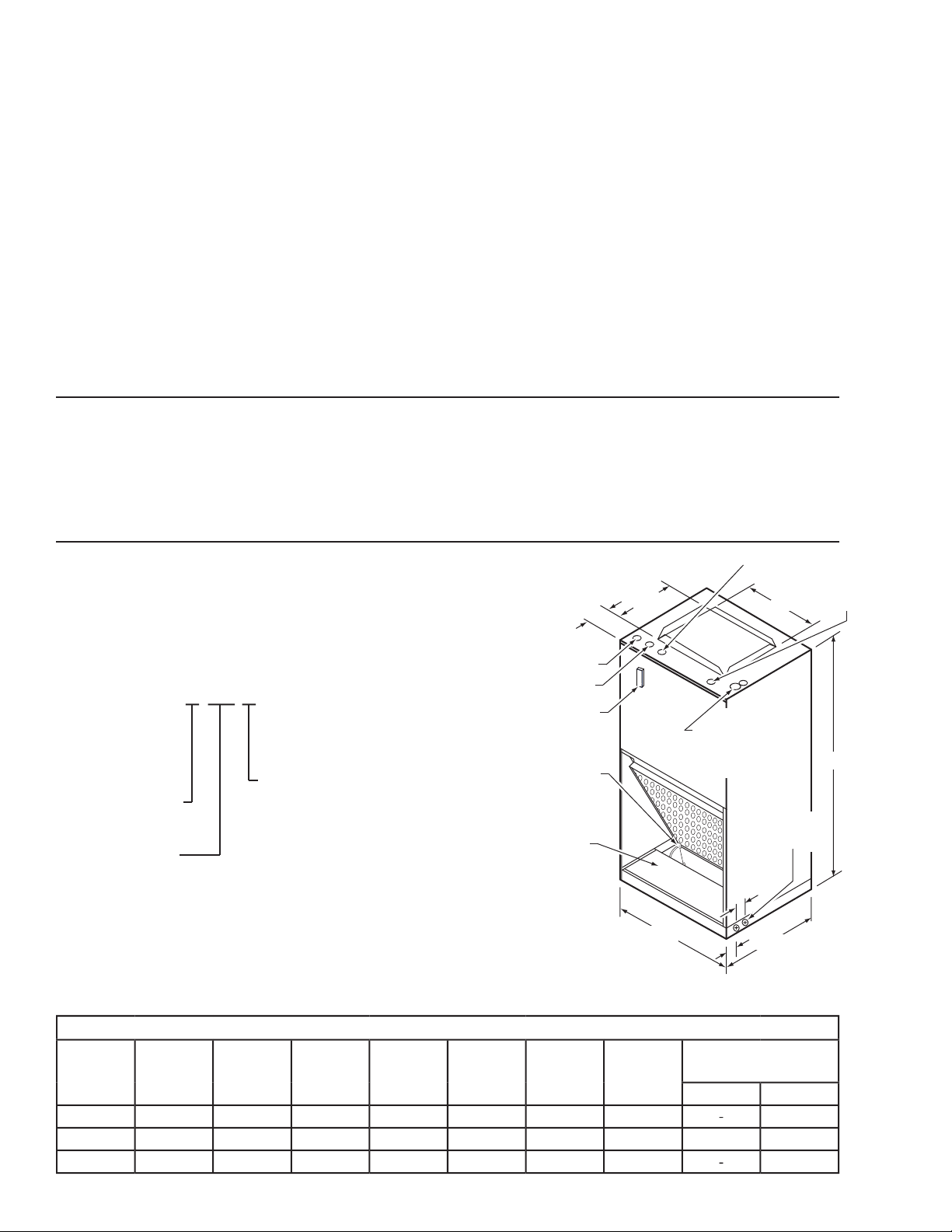
F
D
C
B
2
1.75
A
DRAIN
KNOCKOUTS
(BOTH SIDES)
LOW VOLTAGE
HIGH VOLTAGE
OPTIONAL
OVERFLOW
SWITCH
OPENING WITH
COVER REMOVED:
6-3/8 X 18.5
DISCONNECT
E
SUPPLY AND
RETURN CHILLED
WATER LINES
(5/8"OD COPPER
STUBOUTS)
HOT WATER RETURN
HOT WATER
SUPPLY
A
YCW
YCW-HW
YCWE
10 YCW-31
CFM (100's)
3,4,6,8,10,12
Unit Style
YCW - 2-pipe
YCWE - 2-pipe
w/EH
YCW-HW - 4-pipe
Coil Type
3 - 3 Row
4 - 4 Row
31 - 3 Row Cool,
1 Row Heat
41 - 4 Row Cool,
1 Row Heat
............................................................................................................................................................
.....................................................................................................................................................
.....................................................................................................................................................
YCW UNIT STYLE
........................................................................................................................
WIRING
................................................................................................................................................................
.................................................................................................................................................................
..................................................................................................................................................
Page 3
RECEIVING
FORM 115.20-NOM6 (1106)
INSTALLATION
Material in this shipment has been inspected at the
factory and released to the transportation agency in
good condition. When received, a visual inspection of
all cartons should be made immediately. Any evidence
of rough handling or apparent damage should be noted
on the delivery receipt and the material inspected in
the presence of the carrier’s representative.
If damage is found, a claim should be
filed against the carrier immediately.
STORAGE
If the equipment is not to be immediately installed,
store it in a dry location with the motor protected
against moisture, dust, corrosion and physical damage.
If units are to be stored for six months or longer, see
long term storage requirements (Form 50.20-NM3).
DESCRIPTION
The YCW models are available as 2-pipe cooling
(YCW), 2-pipe cooling with electric heat (YCWE)
and a 4-pipe heating/cooling (YCW-HW). All units are
provided with a 3-speed fan control in the control box
in the fan section (left side), with 24v access on the top
panel, left. Manual and auto changeover thermostats
and the T200 auto speed control thermostats can be
used with this unit. Twenty-four volt (24 v) power is
provided in the unit for thermostat operation.
The 2-pipe cooling unit is provided with a single coil
with connections on the top panel, right side.
form (platform not provided), hung on a closet wall
(use wall hanging kit option) or recessed in a wall
between wall studs (use front panel kit option).
FEATURES
Non-corrosive drain pan, installed in sloped position,
¾” female primary and secondary connections accessible from either side or bottom.
Filters provided, are 1” throwaway accessible from
the front.
Coils and fan motor/blower assemblies accessible
from the front, when installed with the optional front
panel assembly.
Front air return standard, optional bottom return available but requires bottom return option.
Options available are thermostats, wall front panels,
condensate pan overflow switch, closet hanger bracket
kit, bottom return air kit and chilled water coil valve
packages. Consult applications group @ 717-7717073 for details on ordering and availability of these
options.
Cabinet is fully insulated with 1” coated fiberglass
panels.
All units have 0” clearance to combustible surfaces,
so the units can be installed against wall studs and
drywall.
CLEARANCES
The 2-pipe cooling with electric heat is provided
with a single chilled water coil and electric heat elements; coil connections are on the top panel, right
side; electrical connections are on the top panel, left
side and the units are provided with a disconnect on
the front panel.
The 4-pipe heating/cooling unit is provided with 2
coils with single end sheets – cooling connections are
on the top panel, right side and the hot water connections are on the top panel, middle front.
This unit is designed to be installed vertically in the
upflow position and can be installed on a closet plat-
JOHNSON CONTROLS
Clearance required in front of the unit to provide
access to coils, electrical controls and motor/blower
assembly. This clearance should be equal to the depth
of the cabinet.
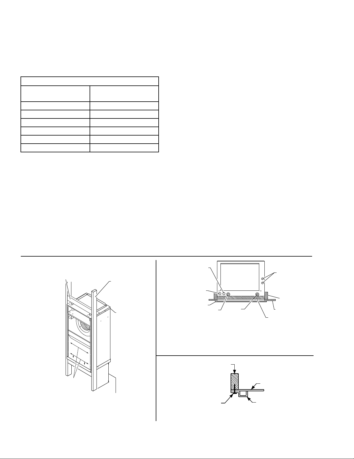
MOUNTING - YCW UNIT STYLE
Recessed In Wall
All units must be installed level to insure proper drainage and operation.
1. Frame the unit as required so the front panel
of the wall unit will be flush with the drywall
surface when installed (see Fig. 3).
3
Page 4
INSTALLATION
VERTICAL 2X 4
WALL STUDS
CLOSET MOUNT:
BRACKET
PLACEMENT
FOR HANGING
MOUNT UNIT
FLUSH WITH
DRY WALL (1/2"
MIN. IN FRONT
OF WALL STUD)
LEAVE SUFFICIENT SPACE
FOR DRAIN PIPING 10" TO 12"
MIN. RECOMMENDED
ATTACH UNIT TO FRAMING
USING SIX SCREWS/NAILS
IN CABINET LOCATIONS
SHOWN
CROSS MEMBER - TOP &
BOTTOM (PLACE UPPER CROSS
MEMBER 3" ABOVE UC UNIT)
SUPPORT FRAMING
RECESSED WALL UNIT TOP VIEW
THERMOSTAT
WIRING
POWER SUPPLY
WIRING
WALL PANEL FRAME
HOT
WATER
OUTLET
HOT
WATER
INLET
DRY WALL
2 X 4 WALL
STUD
CW UNITS:
CHILLED WATER
CONNECTION
Note: Front edge of unit to
be flush with dry wall.
CROSS MEMBER
(ON EDGE)
2 X 4 WALL STUD
WALL PANEL FRAME
SCREW
DETAIL OF WALL PANEL FRAME INSTALLATION
DRY WALL
FORM 115.20-NOM6 (1106)
2. Frame around the perimeter of the unit as
required for securing the drywall. See Table 1
below for drywall openings.
TABLE 1 - DRYWALL OPENINGS
MODEL NUMBER
3YWC 28 x 42
4YWC 28 x 50
6YWC 28 x 58
8YWC 28 x 66
10YWC 28 x 74
12YWC 28 x 82
DRYWALL CUTOUT DIM
HT x WD
3. Mount the unit in its permanent location, making
sure it is level to insure proper drainage and
operation (two 1/2” holes have been provided
on each end of the unit for securing the unit to
the wall studs).
4. After the drywall has been installed, recheck to
make sure the unit’s front panel is flush with the
exterior drywall surface. Shimming of the unit
may be required to get a seal between the unit
and panel.
5. Install the wall panel to the front of the unit using
the 1/4-20 x 1-1/2” long, painted, Phillips head
screws (four on unit sizes 3, 4, 6 and 8; six on
unit sizes 10 and 12) (1/4” cage nuts are located
in the slotted front panel of the unit).
6. Remove the lower return air grille to get access
to the filter.
7. See Fig. 2 for unit details and dimensions.
Hung on a Closet Wall
Unit can be mounted in a closet using the bracket
support option 90PK3.
These brackets mount to the top, back of the cabinet.
See Fig 3 for location.
The unit should be isolated from the wall to be sure
sound is not transferred from the unit to the wall.
Platform Mounted in a Closet
Unit can be set on a platform (provided by others) in
a closet.
Be sure to allow for sufficient space below the platform
for drain piping.
FIG. 3 – CW-HW RECESSED WALL and CLOSET
MOUNTING
4
LD11695A
JOHNSON CONTROLS
Page 5

DUCTWORK
FORM 115.20-NOM6 (1106)
INSTALLATION
Ductwork recommendations are as follows:
• Insulat e to pr event condensa tion during
cooling.
• Size to th e unit op enings ar e general ly
acceptable but are determined by the engineering
drawings.
• Be sure units are ducted per local codes or
national codes, as applicable.
WIRING
Units are provided with wiring diagrams and nameplate data to provide information required for necessary field wiring. All wiring must comply with local
and national code requirements.
Refer to Fig. 3 for access locations.
These units are provided with a class 2 transformer
for 24-volt control circuits. Should any add-on equipment also have a class 2 transformer furnished, care
must be taken to prevent interconnecting outputs of
the two transformers by using a thermostat with isolating contacts. These units are supplied with a 3-speed
control board.
The YCW units (2-pipe cooling) are provided as
standard 120 volt power wired to a disconnect/terminal
block and a ground lug. Fan motor hi, med and low
speed leads are wired to the control board. There may
be an unused motor lead from the motor – it needs to
be capped off. The board is also wired to handle either
24v or 120v control wiring. To use 24v, remove jumpers on the control board. To use a 24v chilled water
control valve, wire the valve in series with the “Y”
connection from the control box, max of 20va.
For 24v wiring using a T420 manual C/O, T421 auto
C/O or the T200 speed control thermostats, you will
need a 6-wire thermostat cable minimum.
The YCW-HW units (4-pipe heating/cooling) are
provided as standard 120 volt power wired to a disconnect/terminal block and a ground lug. Fan motor
hi, med and low speed leads are wired to the control
board. There may be an unused motor lead from the
motor – its needs to be capped off. The board is also
wired to handle either 24v or 120v control wiring. To
use 24v, remove jumpers on the control board. For
your 24v hot water control valve, wire it in series
with the “W” connection. For your 24v chilled water
control valve, wire it in series with the “Y” connection.
For 24v wiring using a T420 manual C/O, T421 auto
C/O or the T200 speed control thermostats, you will
need a 7-wire thermostat cable minimum.
The YCWE units (2-pipe cooling w/electric heat)
are provided as standard 208/240 volt power wired
to a disconnect switch with a ground lug. Fan motor
hi, med and low speed leads are wired to the control
board. There may be an unused motor lead from the
motor – its needs to be capped off. The board is also
wired to handle either 24v or 120v control wiring.
To use 24v, remove jumpers on the control board.
The transformer in the control box is 208/240v with
a common terminal, one for 208v and one for 240v.
Transformer is wired 240v from factory; for 208v application, move the ORG wire on the transformer to
the 208v terminal. For your 24v chilled water control
valve, wire it in series with the “Y” connection. When
using a T420 manual C/O, T421 auto C/O or the T200
speed control thermostats, you will need a 7-wire
thermostat cable minimum. See Table 2 for MCA and
MFS for each unit size/electric heat KW size.
Any devices such as fan switches or
thermostats that have been furnished
by the factory for field installation
must be wired in strict accordance with
the wiring diagram that is supplied
with the unit. Failure to do so could
result in damage or injury.
JOHNSON CONTROLS
5
Page 6

Table 2 - ELECTRICAL DATA
UNIT MODEL
240V 208V 240V 208V 240V 208V 240V 208V
0 0 0.0 1.1 N/A N/A N/A N/A N/A
1 1 0.8 5.3 4.7 7 6 15 15
4CWE
6CWE
8CWE
10CWE
2 2 1.5 9.4 8.3 12 11 15 15
3 3 2.3 13.6 11.9 17 15 20 15
4 4 3.0 17.8 15.5 23 20 25 20
0 0 0.0 1.1 N/A N/A N/A N/A N/A
2 2 1.5 9.4 8.3 12 11 15 15
3 3 2.3 13.6 11.9 17 15 20 15
4 4 3.0 17.8 15.5 23 20 25 20
5 5 3.8 21.9 19.1 28 24 30 25
6 6 4.5 26.1 22.7 33 29 35 30
0 0 0.0 1.7 N/A N/A N/A N/A N/A
3 3 2.3 14.2 12.5 18 16 20 20
4 4 3.0 18.4 16.1 23 21 25 25
5 5 3.8 22.5 19.7 29 25 30 25
6 6 4.5 26.7 23.5 34 30 35 30
8 8 6.0 35.0 30.5 44 39 50 40
0 0 0.0 2.7 N/A N/A N/A N/A N/A
3 3 2.3 15.2 13.5 19 17 20 20
5 5 3.8 23.5 20.7 30 26 30 30
6 6 4.5 27.7 24.3 35 31 35 35
8 8 6.0 36 31.5 45 40 50 40
10 10 7.5 44.4 38.8 56 49 60 50
KW TOTAL AMPS MIN. CIR. AMPACITY
FORM 115.20-NOM6 (1106)
MAX.OVERCURRENT
PROTECTION
6
JOHNSON CONTROLS
Page 7

PIPING
FORM 115.20-NOM6 (1106)
INSTALLATION
All piping connections are 5/8" OD copper tubing
(see Fig.4).
The supply and return piping must be adequately
sized to meet the design water flow requirements as
specified for the specific installation. All chilled water
piping must be insulated to prevent condensation. It
is also recommended that all piping be insulated to
prevent freezing when piping is run in an unconditioned space.
Coil freeze protection is recommended
for applications where the fan coil is
located in ambient air locations (attics,
crawl spaces, etc.) or within structures
that may be unoccupied during freezing conditions. Consult the factory for
additional information.
Piping Precautions
• Flush all piping prior to connection to remove
all debris.
• Use wet cotton rags to cool valve bodies when
soldering.
• Open all valves (midway for hand valves,
manually open on motorized valves) prior to
soldering.
• When soldering to bronze or brass, heat the piping
while in the socket/cup and begin introducing the
solder when the flux boils rapidly. Avoid direct
flame into the solder joint.
• Heat can only be applied to the cup of the valve
body for a minimal time before damage occurs
(even with the use of wet rags).
• Avoid rapid quenching of solder joints, as this
will produce joints of inferior quality.
• Connect all piping per accepted industry
standards and observe all regulations governing
installation of piping systems. When all
connections are complete, the system must be
pressure tested. Repair any solder joint leaks and
gently tighten any leaking valve packing nuts
and piping accessories as required. Hydronic
systems are not designed to hold pressurized air
and should only be tested with water.
When connecting piping or valve
kits to fan coil units, do not bend or
reposition the coil header tubing for
alignment purposes. This could cause
a tubing fracture resulting in a water
leak when water pressure is applied
to the system
JOHNSON CONTROLS
LD12277A
FIG. 4 – CW-HW SERIES UPFLOW WALL / CLOSET FAN COILS
4-Pipe Chilled Water-Hot Water (190 - 1085 CFM)
7
Page 8

INSTALLATION
CONDENSATE DRAIN CONNECTIONS
(With drain cover removed)
(Thermoplastic pan shown)
Drain Piping
Condensate drain lines must be installed with adequate
slope away from the unit to assure positive drainage.
Since the drain pan is located on the suction side of
the blower, a negative pressure exists at the drain pan
and a minimum trap of 1-1/2" must be provided in the
drain line to assure proper drainage.
Drain connections, primary and secondary, are 3/4"
MPT (see Fig. 5 for details).
FORM 115.20-NOM6 (1106)
On units with plastic drain pans the
drain connections must be made hand
tight only.
LD12278
FIG. 5 – CWE SERIES WALL / CLOSET FAN COILS
Chilled Water with Electric Heat
8
JOHNSON CONTROLS
Page 9

SEQUENCE OF OPERATION
YCW With a Chilled Water Coil
The unit will respond to a cooling command from
the thermostat by powering a water control valve
open. The fan will operate at the speed selected at the
thermostat. When the space reaches the temperature
setpoint at the thermostat, the cooling valve will close
and the fan will continue to operate.
When using the T420 manual C/O thermostat and the
TB3-3/TB2-5 jumper is in place, the fan will continue to operate at the fan speed selected. Removing
the jumper will cause the fan to shut down when the
thermostat is satisfied.
When using the T200 thermostat, the stat will automatically regulate the fan speed based on the difference between the space temp and setpoint - @ 4˚F off
setpoint, the fan will run @ HI; @ 3˚F off setpoint, the
fan will run @ MED; @ 2˚F off setpoint, the fan will
run @ LO. When the thermostat is satisfied, the water
valve will be deenergized and the fan will revert to
LO speed.
FORM 115.20-NOM6 (1106)
When using the T200 thermostat, the stat will automatically regulate the fan speed based on the difference between the space temp and setpoint - @ 4˚F off
setpoint, the fan will run @ HI; @ 3˚F off setpoint, the
fan will run @ MED; @ 2˚F off setpoint, the fan will
run @ LO. When the thermostat is satisfied, the water
valve will be deenergized and the fan will revert to
LO speed.
The YCWE With Both a Chilled Water Coil and
Electric Heating Coil.
The unit control thermostat, on a call for heating, will
energize the heater contactor(s). When the thermostat
is set for cooling, it will energize the chilled water
valve on a call for cooling. The fan will operate at
the speed selected at the thermostat. When the space
reaches the temperature setpoint at the thermostat,
the cooling valve will close (on cooling) or the heating contactors will open (on heating) and the fan will
continue to operate.
The YCW-HW with Both a Chilled Water Coil and a
Hot Water Coil.
The unit control thermostat, on a call for heating, will
energize the hot water control valve. When the thermostat is set for cooling, it will energize the chilled
water valve on a call for cooling. The fan will operate
at the speed selected at the thermostat. When the space
reaches the temperature setpoint at the thermostat, the
cooling valve will close (on cooling) or the heating
valve will close (on heating) and the fan will continue
to operate.
When using the T420 manual C/O thermostat and the
TB3-3/TB2-5 jumper is in place, the fan will continue to operate at the fan speed selected. Removing
the jumper will cause the fan to shut down when the
thermostat is satisfied.
When using the T421 auto C/O thermostat and the
TB3-3/TB2-5 jumper is in place, the fan will continue to operate at the fan speed selected. Removing
the jumper will cause the fan to shut down when the
thermostat is satisfied.
When using the T200 thermostat, the stat will automatically regulate the fan speed based on the difference between the space temp and setpoint - @ 4˚F off
setpoint, the fan will run @ HI; @ 3˚F off setpoint, the
fan will run @ MED; @ 2˚F off setpoint, the fan will
run @ LO. When the thermostat is satisfied, the water
valve will be deenergized (on cooling) or the heating
contactor will open (on heating) and the fan will revert
to LO speed.
JOHNSON CONTROLS
9
Page 10

MOTOR
FORM 115.20-NOM6 (1106)
MAINTENANCE
The blower motor should be cleaned annually and if it
has oiling ports, it should be oiled with a good grade
of SAE 20 oil. Normally a few drops of oil in each
bearing is sufficient.
COIL
The coil must be kept clean by any of the following
methods.
1. Cleaning with low-pressure compressed air.
2. Flushing or rinsing with water (a detergent is
advisable for greasy surfaces).
FILTERS
Clean or replace air filters regularly
The intervals at which filters require replacement
depend on local conditions.
Because of dust and lint in the room, room-air filters
load up much more rapidly than outdoor-air filters.
Under normal conditions, the room air filter requires
replacement every six to eight weeks.
To ensure proper maintenance of the filters, it is best
to follow an organized maintenance procedure. The
following one is recommended:
Divide the total number of units on the job into six
equal groups. Each week inspect, clean or replace
the filters in each group, in rotation. This insures
a uniform servicing interval. The interval may be
lengthened or shortened as determined by experience.
If inspection shows only the room-air filter to be dirty,
this one alone should be replaced.
Dirty filters reduce the air and heating
capacities of the unit. When the filters
are excessively dirty, the unit heating
capacity will be so reduced that it is ineffective for heating the room. When
a room fails to heat, always check the
filters.
CLEAN UNIT INTERIOR
Once a year clean the fans and coils of the unit thoroughly. Remove the access panel as necessary.
Wipe the interior of the unit clean with a rag. Wipe
the motor and inside and outside of the fan housings.
(In cooling units, clean out the drain pan.)
10
JOHNSON CONTROLS
Page 11

FORM 115.20-NOM6 (1106)
This Page Intentionally Left Blank
JOHNSON CONTROLS
11
Page 12

www.York.com
www.York.com
air fi lters are clean, installed properly and secured. Use the di rec tion al ar rows or oth er information on the fi lter to
❑
❑
❑
❑
❑
❑
❑
❑
❑
❑
❑
❑
❑
❑ Ensure
❑ Ensure
❑
❑
❑
❑
❑
❑
❑
❑
❑
❑
 Loading...