

Page 1
TECHNICAL GUIDE
ADD - ON COILS
FOR USE WITH SPLIT -SYSTEM
COOLING & HEAT PUMPS
MODELS: MC, PC, FC, HD, UC
600 - 2000 CFM 1.5 - 5 TON COILS
Due to continuous product improvement,
specifications are subject to change without notice.
Visit us on the web at:
www.upgnet.com and www.york.com
Additional rating information can be found at:
www.ahridirectory.org
UPFLOW/DOWNFLOW
FULL CASED
FC
FULL CASED
MULTI-POSITION
MC
UPFLOW
PARTIAL CASED
PC
HORIZONTAL
DUCT
HD
UPFLOW
UNCASED
UC
ISO 9001
Certified Quality
Management System
FOR DISTRIBUTION USE ONLY - NOT TO BE USED AT POINT OF RETAIL SALE
1183385-YTG-A-1114
DESCRIPTION
These evaporator coils are designed to be installed with UPG furnaces or modular air handlers and matched with UPG cooling
and heat pump outdoor units. All coil models are available as
“flex-coil” units without a factory installed metering device. Flexcoil models allow these coils to be used with R-22 or R-410A for
added flexibility to meet refrigerant system choice. An orifice
metering device or a R-410A TXV should be installed in the field
to meet your system requirements.
FC Models, Full Case Coils - Full cased coils are suitable for
use in upflow or downflow applications.
MC Models, Multi-Position Coils - MC coils have the added
flexibility that allow them to be installed in any position - upflow,
downflow, or horizontal (right or left). This coil can be easily
installed with a UPG furnace or modular air handler in any configuration.
PC Models, Partial Case Coils - These coils are designed for
installation on top of upflow furnaces. The partial case height on
these coils allows for the flexibility of fabricating the upper portion
of the coil casing in the field. The partial cased coils are for use in
upflow only applications.
UC Models, Uncased Coils - These coils are designed for installation on top of upflow furnaces, and they are to be used for
upflow only applications. The uncased coils allows field modification of the furnace duct for the coil installation.
HD Models, Horizontal Duct Coils - Dedicated horizontal, slab
coil available for cooling applications. Field transition may be
required.
FEATURES
Rust-proof plastic drain pans - The vertical and horizontal drain
pans on these coils are made of a fiberglass reinforced thermoset
polymer that will not rust or compromise stability at high temperatures.
Insulated Cabinet - Evaporator coil cabinets are thermally insulated with foil faced insulation to prevent sweating. HD coils use
fiberglass Tuf-Skin® insulation.
Internally Clean - All evaporator coils are factory leak-tested,
dehydrated, sealed and shipped with a holding charge. The suction and liquid lines are sealed with spun copper fittings with easy
access to attach line set.
Durable Finish Inside and Out - Coil casings are made of prepainted steel. Pre-treated flat galvanized steel provides a better
paint to steel bond, which resists corrosion and rust creep. All
internal metal parts are made of G90 galvanized steel.
Optimum Heat Transfer - Using the latest in heat transfer technology, staggered rows of copper tubes are mechanically
expanded into aluminum fins to provide optimum air to surface
contact for ample moisture removal as well as high performance
ratings.
ACCESSORIES
Refer to Price Manual for specific model numbers.
TXV Kits - Thermal expansion valve kits are available for flex-coil
applications, for converting R-22 to R-410A refrigerant, or as a
service replacement. All TXV kits are non-braze. All connections
are bolt-on including the valve assembly and equalizer tube. No
orifice or any other metering device is to be used in conjunction
with the TXV.
Coil Casing Without Coil - Coil casings are available in four
widths that can be installed with the furnace or modular air handler during initial installation. This option is available to allow the
installer the flexibility to add the coil at a later date without duct
modifications.
UVC Germicidal Light - The UVC technology effectively prevents mold, bacteria, and other microorganisms that develop in
air handling systems. The UVC Light Kit provides safe, continuous cleaning while actually saving money by reducing HVAC system maintenance and energy consumption.
Page 2
1183385-YTG-A-1114
20 1/4”
D
20 3/8”
(Opening)
C
A
B
21 1/2”
BOTTOM OPENING
DIMENSIONS
-
-
-
BOTTOM OPENING
DIMENSIONS
21-1/2”
20-1/4”
C
(Opening)
20-3/8”
(Opening)
B
A
D
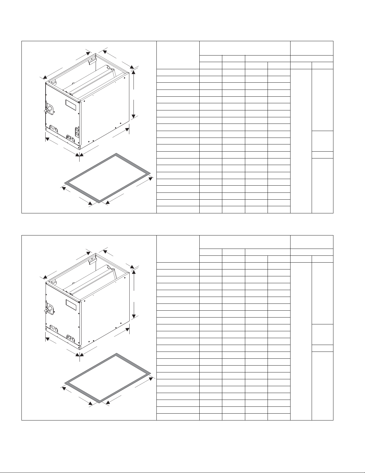
DIMENSIONS
Dimensions
Models
MC18A3X(C,T)1 22 14-1/2 13-3/8 13-1/2
MC18B3X(C,T)1 22 17-1/2 16-3/8 16-1/2
MC24A3X(C,T)1 26-1/2 14-1/2 13-3/8 13-1/2
MC24B3X(C,T)1 26-1/2 17-1/2 16-3/8 16-1/2
MC30A3X(C,T)1 26-1/2 14-1/2 13-3/8 13-1/2
MC30B3X(C,T)1 26-1/2 17-1/2 16-3/8 16-1/2
MC32A3X(C,T)1 22 14-1/2 13-3/8 13-1/2
MC35B3X(C,T)1 22 17-1/2 16-3/8 16-1/2
MC35C3X(C,T)1 22 21 19-7/8 20
MC36A3X(C,T)1 26-1/2 14-1/2 13-3/8 13-1/2
MC36C3X(C,T)1 26-1/2 21 19-7/8 20
MC37A3X(C,T)1 26-1/2 14-1/2 13-3/8 13-1/2 3/4
MC42B3X(C,T)1 32 17-1/2 16-3/8 16-1/2
MC42C3X(C,T)1 32 21 19-7/8 20
MC43B3X(C,T)1 26-1/2 17-1/2 16-3/8 16-1/2
MC43C3X(C,T)1 26-1/2 21 19-7/8 20
MC48C3X(C,T)1 32 21 19-7/8 20
MC48D3X(C,T)1 32 24-1/2 23-3/8 23-1/2
MC60D3X(C,T)1 32 24-1/2 23-3/8 23-1/2
MC62D3X(C,T)1 36 24-1/2 23-3/8 23-1/2
1. All dimensions are in inches.
2. Refrigerant line sizes may require larger lines for extended line lengths. See Applicati on Data part number 247077.
Height Width Opening Widths Line Size
ABCDLiquidVapor
1
Refrigerant
Connections
2
3/4
3/8
7/8MC36B3X(C,T)1 26-1/2 17-1/2 16-3/8 16-1/2
7/8
1. All dimensions are in inches.
2. Refrigerant line sizes may require larger lines for extended line lengths. See Applicati on Data part number 247077.
2 Johnson Controls Unitary Products
Refrigerant
Connections
2
Models
Dimensions
1
Height Width Opening Widths Line Size
ABCDLiquidVapor
FC18A3XC1 18 14-1/2 13-3/8 13-1/2
FC18B3XC1 18 17-1/2 16-3/8 16-1/2
FC24A3XC1 22 14-1/2 13-3/8 13-1/2
FC24B3XC1 22 17-1/2 16-3/8 16-1/2
FC30A3XC1 22 14-1/2 13-3/8 13-1/2
3/4
FC30B3XC1 22 17-1/2 16-3/8 16-1/2
FC32A3XC1 20 14-1/2 13-3/8 13-1/2
FC35B3XC1 20 17-1/2 16-3/8 16-1/2
FC35C3XC1 20 21 19-7/8 20
FC36A3XC1 24-1/2 14-1/2 13-3/8 13-1/2
7/8FC36B3XC1 24-1/2 17-1/2 16-3/8 16-1/2
FC36C3XC1 24-1/2 21 19-7/8 20
3/8
FC37A3XC1 24-1/2 14-1/2 13-3/8 13-1/2 3/4
FC42B3XC1 28 17-1/2 16-3/8 16-1/2
FC42C3XC1 28 21 19-7/8 20
FC43B3XC1 24-1/2 17-1/2 16-3/8 16-1/2
FC43C3XC1 24-1/2 21 19-7/8 20
FC48C3XC1 28 21 19-7/8 20
FC48D3XC1 28 24-1/2 23-3/8 23-1/2
7/8
FC60C3XC1 28 21 19-7/8 20
FC60D3XC1 28 24-1/2 23-3/8 23-1/2
FC62D3XC1 32 24-1/2 23-3/8 23-1/2
FC64D3XC1 36 24-1/2 23-3/8 23-1/2
Page 3
1183385-YTG-A-1114
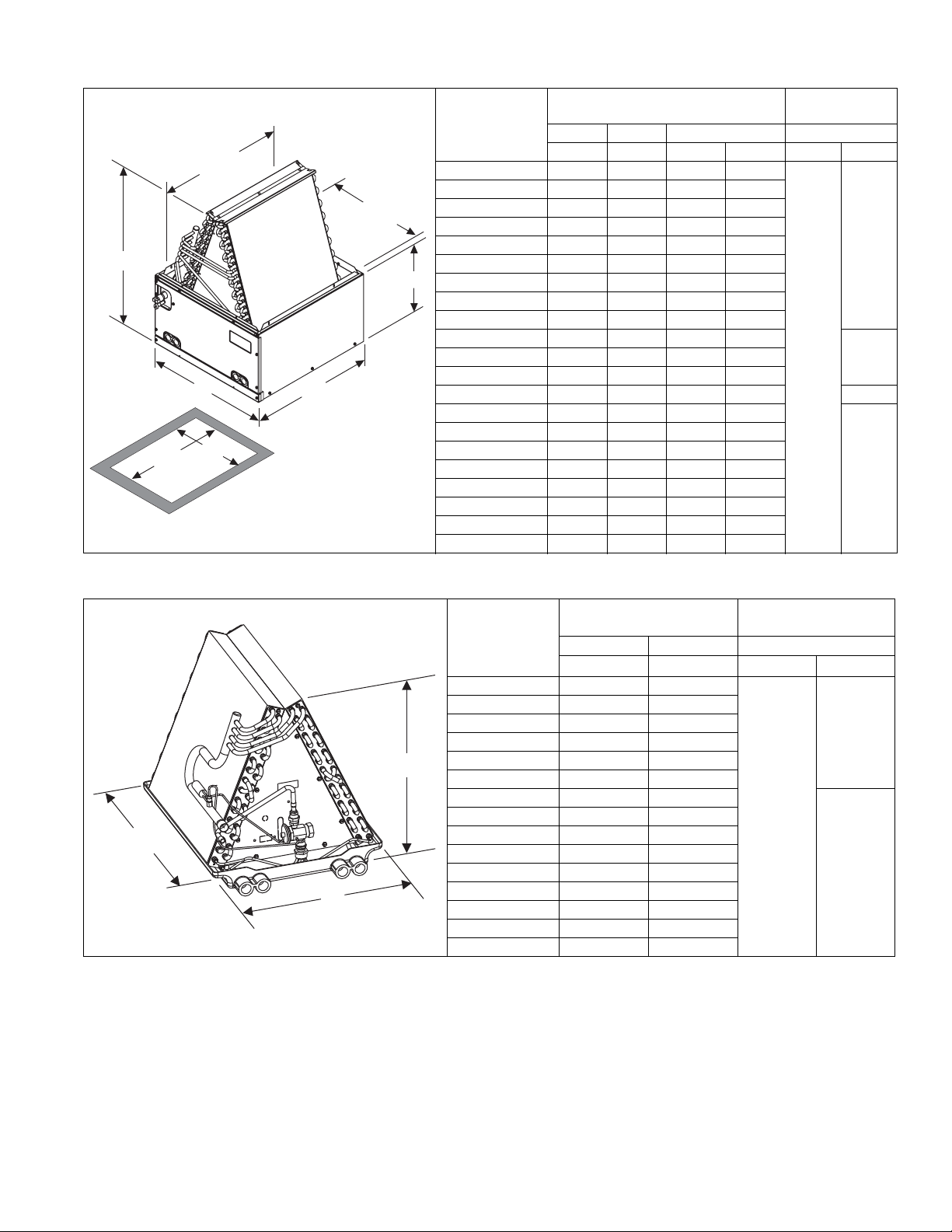
BOTTOM
OPENING
DIMENSIONS
20 1/4”
D
-
20 3/8”
(Opening)
A
C
(Opening)
12”
B
21 1/2”
-
-
21.0
A
B
Dimensions
Models
Height Width Opening Widths Line Size
ABCDLiquidVapor
PC18A3XC1 17-3/4 14-1/2 13-3/8 13-1/2
PC18B3XC1 17 17-1/2 16-3/8 16-1/2
PC24A3XC1 21-7/8 14-1/2 13-3/8 13-1/2
PC24B3XC1 21-3/8 17-1/2 16-3/8 16-1/2
PC30A3XC1 21-7/8 14-1/2 13-3/8 13-/2
PC30B3XC1 21-3/8 17-1/2 16-3/8 16-1/2
PC32A3XC1 20 14-1/2 13-3/8 13-1/2
PC35B3XC1 18-7/8 17-1/2 16-3/8 16-1/2
PC35C3XC1 18-3/4 21 19-7/8 20
PC36A3XC1 23-7/8 14-1/2 13-3/8 13-1/2
PC36C3XC1 22-7/8 21 19-7/8 20
PC37A3XC1 23-7/8 14-1/2 13-3/8 13-1/2 3/4
PC42B3XC1 27-5/8 17-1/2 16-3/8 16-1/2
PC42C3XC1 27-1/8 21 19-7/8 20
PC43B3XC1 23-1/8 17-1/2 16-3/8 16-1/2
PC43C3XC1 22-5/8 21 19-7/8 20
PC48C3XC1 25-3/8 21 19-7/8 20
PC48D3XC1 24-5/8 24-1/2 23-3/8 23-1/2
PC60C3XC1 27-1/2 21 19-7/8 20
PC60D3XC1 26-7/8 24-1/2 23-3/8 23-1/2
1. All dimensions are in inches.
2. Refrigerant line sizes may require larger lines for extended line lengths. See Application Data part number 247077.
1
Refrigerant
Connections
2
3/4
3/8
7/8PC36B3XC1 23-1/8 17-1/2 16-3/8 16-1/2
7/8
Refrigerant
Connections
2
Models
Dimensions
1
Height Width Line Size
A B Liquid Vapor
UC18A3XC1 17 13
UC18B3XC1 16-1/2 16
UC24A3XC1 21 13
UC24B3XC1 20-1/2 16
UC30A3XC1 21 13
UC30B3XC1 20-1/2 16
UC36A3XC1 23-1/2 13
UC36B3XC1 22-1/2 16
3/8
UC36C3XC1 22 19-1/2
UC42B3XC1 26-1/2 16
UC42C3XC1 25-1/2 19-1/2
UC48C3XC1 23-1/2 19-1/2
UC48D3XC1 23 23
UC60C3XC1 25-1/2 19-1/2
UC60D3XC1 25 23
1. All dimensions are in inches.
2. Refrigerant line sizes may require larger lines for extended line lengths. See Application Data part number 247077.
3/4
7/8
Johnson Controls Unitary Products 3
Page 4
1183385-YTG-A-1114
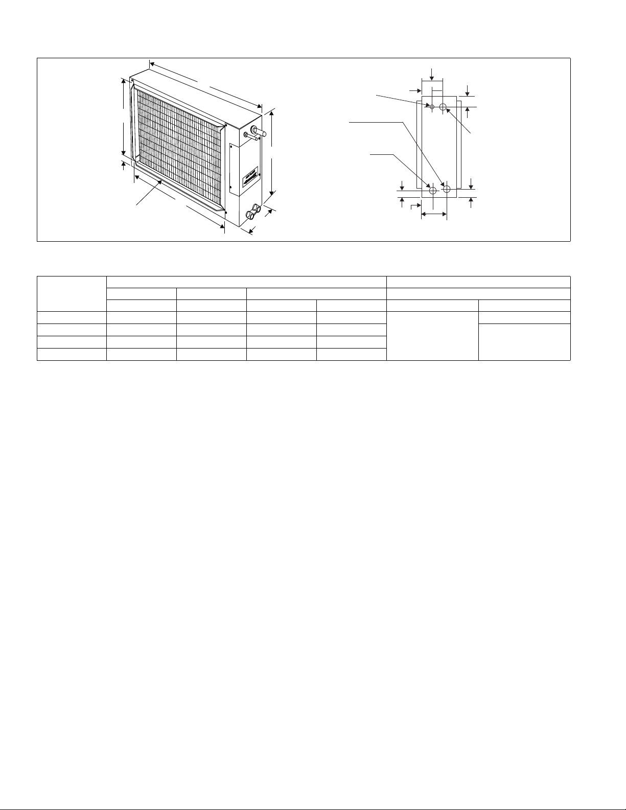
1-3/4
D
5-5/8
A
B
C
3-3/4
2-5/8
1-3/8
OPENING
FOR
VAPOR
CONN.
OPENING
FOR
LIQUID
CONN.
OPENING
FOR
3/4 NPT
SECONDARY
DRAIN CONN.
OPENING
FOR
3/4 NPT
PRIMARY
DRAIN CONN.
7/8
1-7/8
4-1/8
1-3/8
OUTLET SAME
SIZE AS INLET
(3/4” FLANGE)
COIL - HD
DIMENSIONS - HD Coils
Dimensions
Models
Height Width Opening Widths Line Size
ABCD Liquid Vapor
HD24S3XC1 24 28-3/4 21-5/8 23-3/4
HD36S3XC1 28 28-3/4 25-5/8 23-3/4
HD60S3XC1 30 34-3/4 27-5/8 29-3/4
1. All dimensions are in inches.
2. Refrigerant line sizes may require larger lines for extended line lengths. See Applicati on Data part number 247077.
1
Refrigerant Connections
3/8
2
3/4
7/8HD48S3XC1 28 34-3/4 25-5/8 29-3/4
4 Johnson Controls Unitary Products
Page 5

1183385-YTG-A-1114
COOLING CAPACITY - Coil Only
Model
FC18A
PC18A
FC18B
PC18B
FC24A
PC24A
FC24B
PC24B
FC30(A,B)
PC30(A,B)
FC32A
PC32A
FC35(B,C)
PC35(B,C)
FC37A
PC37A
FC36A
PC36A
FC36(B,C)
PC36(B,C)
FC42(B,C)
PC42(B,C)
FC43(B,C)
PC43(B,C)
FC48(C,D)
PC48(C,D)
FC60(C,D)
PC60(C,D)
FC62D 1850
FC64D 1850
Rated
CFM
675
675
850
850
1025
1200
1150
1250
1400
1400
1620
1850
1
Entering
Air °F
(Dry/Wet Bulb)
MBH @ Evaporator Temperature and Corresponding Pressure °F / PSIG
35 / 61.5 40 / 68.5 45 / 76.0 50 / 84.0
UPFLOW "A" TYPE
85/72 25.3 23.1 20.6 17.9
80/67 23.4 21.1 18.7 16.1
75/62 19.2 12.0 18.7 12.4
70/57 15.6 13.5 11.3 8.8
85/72 28.1 25.7 22.9 19.9
80/67 26.0 23.5 20.8 17.9
75/62 21.3 18.9 16.4 13.7
70/57 17.3 15.0 12.6 9.8
85/72 35.6 32.5 29.0 25.2
80/67 32.9 29.7 26.3 22.7
75/62 27.0 23.9 20.7 17.4
70/57 21.9 19.0 15.9 12.4
85/72 35.6 32.5 29.0 25.2
80/67 32.9 29.7 26.3 22.7
75/62 27.0 23.9 20.7 17.4
70/57 21.9 19.0 15.9 12.4
85/72 38.9 35.4 31.6 27.6
80/67 33.9 30.3 26.8 23.0
75/62 27.3 23.7 22.5 18.0
70/57 22.6 20.1 17.5 14.8
85/72 58.7 50.5 42.1 33.2
80/67 47.0 39.5 32.2 24.6
75/62 36.7 29.2 23.8 19.9
70/57 31.5 27.6 22.4 18.8
85/72 46.0 41.9 37.4 32.9
80/67 36.8 32.5 28.5 24.2
75/62 28.8 24.1 26.4 19.6
70/57 24.7 22.9 21.1 19.6
85/72 51.1 46.5 41.5 36.6
80/67 40.9 36.1 31.7 26.9
75/62 32.0 26.8 29.3 21.8
70/57 27.4 25.4 23.4 21.8
85/72 73.1 62.9 52.4 41.4
80/67 58.6 49.1 40.0 30.6
75/62 45.7 36.3 29.6 24.7
70/57 39.2 34.3 27.9 23.4
85/72 76.8 66.0 55.0 43.4
80/67 61.5 51.6 42.0 32.1
75/62 47.9 38.1 31.1 26.0
70/57 41.2 36.0 29.3 24.6
85/72 82.2 70.7 58.9 46.5
80/67 65.8 55.3 45.0 34.4
75/62 51.4 40.9 33.3 27.9
70/57 44.1 38.6 32.3 26.5
85/72 100.9 85.0 68.9 52.3
80/67 80.8 66.6 52.6 38.6
75/62 62.9 49.3 38.8 31.2
70/57 54.1 46.6 37.4 29.8
85/72 105.9 89.3 72.4 54.9
80/67 84.8 70.0 55.2 40.5
75/62 66.0 51.8 40.8 32.8
70/57 56.8 48.9 39.3 31.2
85/72 124.4 109.4 94.1 78.0
80/67 100.9 87.0 72.1 56.2
75/62 80.3 66.7 52.5 37.2
70/57 61.8 48.2 34.8 24.3
Johnson Controls Unitary Products 5
Page 6

1183385-YTG-A-1114
1. - See Condensing Unit or Heat Pump Technical Guide for Total Cooling Capacity and Sensible Capacity.
COOLING CAPACITY - COIL ONLY
Model Coil Rated CFM
MC18A 550
MC18B 650
MC24(A,B) 850
MC30(A,B)
MC32A
MC35(B,C)
MC37A
MC36A 1150
MC36B 1250
MC36C 1250
MC42(B,C) 1400
MC43(B,C) 1400
MC48(C,D) 1650
MC60D 1825
MC62D 2000
1. See Condensing Unit or Heat Pump Technical Guide for Total Cooling Capacity and Sensible Capacity.
1025
1200
1
Entering Air °F
(Dry/Wet Bulb)
MBH@ Evaporator Temperature and Corresponding Pressure °F / PSIG
35 / 61.5 40 / 68.5 45 / 76.0 50 / 84.0
FULL-CASED “A” TYPE MULTI-POSITION
85/72 25.8 23.5 21.0 18.2
80/67 23.7 21.5 19.0 16.4
75/62 19.5 17.3 14.9 12.6
70/57 15.8 13.5 11.5 9.0
85/72 28.7 26.1 23.3 20.2
80/67 26.4 23.9 21.1 18.2
75/62 21.6 19.2 16.6 14.0
70/57 17.5 15.2 12.8 10.0
85/72 36.3 33.0 29.5 25.6
80/67 33.4 30.2 26.7 23.1
75/62 27.4 24.3 21.0 17.7
70/57 22.2 19.3 16.2 12.6
85/72 41.5 37.8 33.7 29.5
80/67 36.2 32.4 28.6 24.5
75/62 29.1 25.3 24.0 19.2
70/57 24.1 21.5 18.7 15.8
85/72 59.9 51.5 42.9 33.9
80/67 48.0 40.3 32.8 25.1
75/62 37.4 29.8 24.3 20.3
70/57 32.1 28.1 22.9 19.2
85/72 46.8 42.6 38.1 33.6
80/67 37.5 33.1 29.1 24.7
75/62 29.3 24.6 26.8 20.0
70/57 25.1 23.2 21.4 20.0
85/72 52.0 47.3 42.3 37.3
80/67 41.7 36.8 32.3 27.4
75/62 32.5 27.3 29.8 22.2
70/57 27.9 25.8 23.8 22.2
85/72 53.4 48.6 43.4 38.3
80/67 42.8 37.8 33.1 28.2
75/62 33.4 28.1 30.6 22.8
70/57 28.7 26.5 24.5 22.8
85/72 74.6 64.1 53.4 42.2
80/67 59.8 50.1 40.8 31.2
75/62 46.6 37.1 30.2 25.2
70/57 40.0 35.0 28.5 23.9
85/72 78.3 67.4 56.1 44.3
80/67 62.7 52.6 42.9 32.8
75/62 48.9 38.9 31.7 26.5
70/57 42.0 36.8 29.9 25.1
85/72 83.9 72.1 60.1 47.4
80/67 67.2 56.4 45.9 35.1
75/62 52.4 41.7 33.9 28.4
70/57 45.0 39.4 33.0 27.0
85/72 102.9 86.7 70.3 53.3
80/67 82.4 68.0 53.7 39.4
75/62 64.2 50.3 39.6 31.8
70/57 55.1 47.5 38.1 30.3
85/72 107.0 90.2 73.1 55.5
80/67 85.7 70.7 55.8 40.9
75/62 66.7 52.3 41.2 33.1
70/57 57.4 49.4 39.7 31.6
6 Johnson Controls Unitary Products
Page 7

RATED
CFM
1
ENTERING
AIR F
(Dry/Wet Bulb)
HORIZONTAL DUCT TYPE
MBH @ Evaporator Temperature and Corresponding Pressure °F/ PSIG
35 / 61.5 40 / 68.5 45 / 76.0 50 / 84.0
COOLING CAPACITY - Coil Only
MODEL
85/72 35.3 32.4 28.7 24.9
HD24S 815
80/67 32.6 29.4 26.0 22.5
75/62 26.7 23.7 20.5 17.2
70/57 21.7 18.8 15.7 12.3
85/72 57.9 52.7 47.1 41.5
HD36S 1192
80/67 46.4 41.1 35.9 30.4
75/62 36.2 30.4 26.5 24.7
70/57 31.1 28.7 26.5 24.7
85/72 83.4 71.7 59.7 47.1
HD48S 1610
80/67 66.8 56.1 45.6 34.9
75/62 52.1 41.5 33.7 28.3
70/57 44.7 39.2 33.7 28.3
85/72 133.0 112.4 90.9 69.2
HD60S 2100
80/67 106.5 87.9 69.4 50.0
75/62 83.0 65.0 51.3 41.1
70/57 71.2 61.4 51.3 41.1
1. See Condensing Unit or Heat Pump Technical Guide for Total Cooling Capacity and Sensible Capacity.
1183385-YTG-A-1114
COOLING CAPACITY - COIL ONLY
Model Coil Rated CFM
1
Entering Air °F
(Dry/Wet Bulb)
MBH@ Evaporator Temperature and Corresponding Pressure °F / PSIG
35 / 61.5 40 / 68.5 45 / 76.0 50 / 84.0
Uncased Upflow
85/72 23.3 21.3 19.0 17.5
UC18(A,B) 600
80/67 21.5 19.5 17.3 14.9
75/62 17.7 15.6 13.5 11.4
70/57 14.4 12.4 10.4 8.0
85/72 27.4 25.0 22.3 19.4
UC24(A,B) 800
80/67 25.3 22.9 20.3 17.5
75/62 20.8 18.4 15.9 13.4
70/57 16.9 14.6 12.2 9.4
85/72 35.2 32.0 28.6 24.8
UC30(A,B) 1000
80/67 32.4 28.6 25.3 21.9
75/62 26.6 23.6 21.5 18.7
70/57 25.2 22.7 20.2 17.6
85/72 46.8 42.7 37.9 33.0
UC36A 1150
80/67 43.1 39.2 34.9 30.4
75/62 35.3 32.1 28.6 24.9
70/57 33.3 26.9 26.9 23.4
85/72 49.3 44.9 39.9 34.7
UC36(B,C) 1200
80/67 45.4 41.3 36.7 32.0
75/62 37.2 33.8 30.1 26.2
70/57 35.0 28.3 28.3 24.6
85/72 86.7 73.0 59.2 44.9
UC42(B,C) 1400
80/67 69.4 57.2 45.2 33.1
75/62 54.0 42.3 33.4 26.8
70/57 46.4 40.0 33.4 26.8
85/72 62.4 56.8 50.5 44.4
UC48(C,D) 1600
80/67 57.4 53.2 46.5 40.5
75/62 47.1 42.8 38.1 33.2
70/57 44.3 40.3 35.8 31.2
85/72 95.4 82.1 68.4 54.0
UC60(C,D) 1800
80/67 76.4 64.1 52.2 39.9
75/62 59.6 47.4 38.6 32.4
70/57 51.2 44.8 38.6 32.4
1. See Condensing Unit or Heat Pump Technical Guide for Total Cooling Capacity and Sensible Capacity.
Johnson Controls Unitary Products 7
Page 8

1183385-YTG-A-1114
APPLICATION FACTOR-RATED CFM VS. ACTUAL CFM
% OF RATED AIR FLOW 80% 90% Rated CFM 110% 120%
CAPACITY FACTOR 0.96 0.98 1.00 1.02 1.03
* Do not exceed minimum/maximum CFM limits shown under Air Flow Data.
APPLICATION LIMITATIONS
These units must be installed in accordance with all national
and local safety codes.
Air flow must be within the minimum and maximum limits
approved for electric heat, evaporator coils and outdoor units.
STATIC PRESSURE VS. AIRFLOW
(BASED ON WET COIL)
HORIZONTAL - DUCT TYPE
Model Airflow Wet Coil
600 0.02
HD24S
HD36S
HD48S
HD60S
800 0.09
1000 0.19
1000 0.19
1200 0.28
1400 0.38
1200 0.14
1400 0.19
1600 0.25
1800 0.32
1600 0.16
1800 0.20
2000 0.25
2200 0.30
UNCASED UPFLOW - “A” TYPE
Model Airflow Wet Coil
UC18A
UC18B
UC24A
UC24B
UC30A
UC30B
UC36A
UC36B
UC36C
UC42B
UC42C
UC48C
UC48D
UC60C
UC60D
600 0.16
800 0.23
1000 0.30
600 0.14
800 0.20
1000 0.26
600 0.15
800 0.21
1000 0.27
600 0.13
800 0.18
1000 0.23
800 0.21
1000 0.27
1200 0.33
800 0.18
1000 0.23
1200 0.29
1000 0.24
1200 0.32
1400 0.40
1000 0.15
1200 0.22
1400 0.28
1000 0.10
1200 0.15
1400 0.20
1200 0.21
1400 0.28
1600 0.34
1200 0.14
1400 0.19
1600 0.24
1800 0.28
1200 0.18
1400 0.24
1600 0.29
1800 0.35
1200 0.14
1400 0.20
1600 0.25
1800 0.30
1600 0.28
1800 0.33
2000 0.38
2200 0.43
1600 0.21
1800 0.27
2000 0.32
2200 0.38
8 Johnson Controls Unitary Products
Page 9

1183385-YTG-A-1114
UPFLOW CASED “A” TYPE
Model Airflow Wet Coil
FC18A
PC18A
FC18B
PC18B
FC24A
PC24A
FC24B
PC24B
FC30A, PC30A
FC32A, PC32A
FC30B
PC30B
FC35B
PC35B
FC35C
PC35C
FC36A
PC36A
FC36B
PC36B
FC37A
PC37A
FC36C
PC36C
FC42B
PC42B
FC42C, PC42C
FC43B, PC43B
FC43C
PC43C
FC48C
PC48C
FC48D
PC48D
FC60C
PC60C
FC60D
PC60D
FC62D
FC64D
CASED “A” TYPE MULTI-POSITION
600 0.16
800 0.23
1000 0.30
600 0.14
800 0.20
1000 0.26
600 0.15
800 0.21
1000 0.27
600 0.13
800 0.18
1000 0.23
800 0.21
1000 0.27
1200 0.33
800 0.18
1000 0.23
1200 0.29
800 0.16
1000 0.22
1200 0.29
800 0.14
1000 0.20
1200 0.27
1000 0.24
1200 0.32
1400 0.40
1000 0.15
1200 0.22
1400 0.28
800 0.13
1000 0.19
1200 0.26
1000 0.10
1200 0.15
1400 0.20
1200 0.21
1400 0.28
1600 0.34
1800 0.40
1200 0.14
1400 0.19
1600 0.24
1800 0.28
1000 0.15
1200 0.21
1400 0.28
1600 0.34
1600 0.29
1800 0.35
2000 0.40
2200 0.46
1600 0.25
1800 0.30
2000 0.35
2200 0.40
1600 0.28
1800 0.33
2000 0.38
2200 0.43
1600 0.21
1800 0.27
2000 0.32
2200 0.38
1600 0.18
1800 0.23
2000 0.29
1600 0.21
1800 0.26
2000 0.30
Model Airflow Wet Coil
MC18A
MC18B
MC24A
MC24B
MC30A
MC32A
MC30B
MC35B
MC35C
MC36A
MC37A
MC36B
MC36C
MC42B
MC42C
MC43C
MC48C
MC48D
MC60D
MC62D
600 0.22
800 0.29
1000 0.36
600 0.20
800 0.26
1000 0.32
600 0.21
800 0.27
1000 0.33
600 0.19
800 0.24
1000 0.29
600 0.21
800 0.27
1000 0.33
600 0.19
800 0.24
1000 0.29
600 0.22
800 0.26
1000 0.34
600 0.20
800 0.24
1000 0.32
800 0.22
1000 0.30
1200 0.38
800 0.19
1000 0.25
1200 0.32
800 0.15
1000 0.21
1200 0.28
1000 0.16
1200 0.21
1400 0.26
1200 0.27
1400 0.34
1600 0.40
1200 0.20
1400 0.25
1600 0.30
1800 0.34
1200 0.26
1400 0.31
1600 0.36
1800 0.41
1200 0.24
1400 0.30
1600 0.35
1800 0.41
1200 0.20
1400 0.26
1600 0.31
1800 0.36
1600 0.27
1800 0.33
2000 0.38
2200 0.44
1600 0.24
1800 0.29
2000 0.34
Johnson Controls Unitary Products 9
Page 10

1183385-YTG-A-1114
PHYSICAL DATA
UNCASED UPFLOW - “A” TYPE
Model Application
UC18A
UC18B Sweat 3.67 2 14 (2) 16 x 16.5 1 x 0.866 3/8 Enhanced None 20
UC24A
UC24B Sweat 4.58 2 14 (2) 20 x 16.5 1 x 0.866 3/8 Enhanced None 23
UC30A
UC30B Sweat 4.58 2 14 (2) 20 x 16.5 1 x 0.866 3/8 Enhanced None 23
Cooling/ Heat Pump
Cooling/ Heat Pump
Cooling/ Heat Pump
UC36A
UC36B Sweat 5.04 2 14 (2) 22 x 16.5 1 x 0.866 3/8 Enhanced None 28
Cooling/ Heat Pump
Refrig.
Conn.
Types
Sweat 3.67 2 14 (2) 16 x 16.5 1 x 0.866 3/8 Enhanced None 18
Sweat 4.58 2 14 (2) 20 x 16.5 1 x 0.866 3/8 Enhanced None 22
Sweat 4.58 2 14 (2) 20 x 16.5 1 x 0.866 3/8 Enhanced None 22
Sweat 5.04 2 14 (2) 22 x 16.5 1 x 0.866 3/8 Enhanced None 25
UC36C Sweat 5.04 2 14 (2) 22 x 16.5 1 x 0.866 3/8 Enhanced None 30
UC42B
UC42C Sweat 5.96 2 14 (2) 26 x 16.5 1 x 0.866 3/8 Enhanced None 36
UC48C
UC48D Sweat 5.50 3 12 (2) 24 x 16.5 1 x 0.866 3/8 Enhanced None 42
UC60C
UC60D Sweat 5.96 3 12 (2) 26 x 16.5 1 x 0.866 3/8 Enhanced None 45
Cooling/ Heat Pump
Cooling/ Heat Pump
Cooling/ Heat Pump
Sweat 5.96 2 14 (2) 26 x 16.5 1 x 0.866 3/8 Enhanced None 34
Sweat 5.50 3 12 (2) 24 x 16.5 1 x 0.866 3/8 Enhanced None 38
Sweat 5.96 3 12 (2) 26 x 16.5 1 x 0.866 3/8 Enhanced None 42
HORIZONTAL - DUCT TYPE
Model Application
HD24S Cooling Sweat 3.67 3 12 22 x 24 1 x 0.866 3/8 Enhanced None 33
HD36S Cooling Sweat 4.23 3 12 26 x 24 1 x 0.866 3/8 Enhanced None 35
HD48S Cooling Sweat 5.29 3 12 26 x 30 1 x 0.866 3/8 Enhanced None 38
HD60S Cooling Sweat 5.71 3 12 28 x 30 1 x 0.866 3/8 Enhanced None 46
Refrig.
Conn.
Types
Face
Area
(Sq. Ft.)
Face
Area
(Sq. Ft.)
Rows
Deep
Rows
Deep
Fin
Per
In.
Fin
Per
In.
Coil Size
Coil Size
Tube
Geometry
Tube
Geometry
Tube
Dia.
Tube
Dia.
Fin
Type
Fin
Type
TXV
TXV
Operatin
g
Weight
(Lbs.)
Operating
Weight
(Lbs.)
CASED UPFLOW/DOWNFLOW AND PARTIAL CASED
Model Application
Refrig.
Conn.
Types
FC18A Cooling/Heat Pump Sweat 3.4 2 14 (2) 14 x 17.5 1 x 0.866 3/8 Enhanced None 42
FC18B Cooling/Heat Pump Sweat 3.4 2 14 (2) 14 x 17.5 1 x 0.866 3/8 Enhanced None 44
FC24A Cooling/Heat Pump Sweat 4.38 2 14 (2) 18 x 17.5 1 x 0.866 3/8 Enhanced None 46
FC24B Cooling/Heat Pump Sweat 4.38 2 14 (2) 18 x 17.5 1 x 0.866 3/8 Enhanced None 50
FC30A Cooling/Heat Pump Sweat 4.38 2 14 (2) 18 x 17.5 1 x 0.866 3/8 Enhanced None 46
FC30B Cooling/Heat Pump Sweat 4.38 2 14 (2) 18 x 17.5 1 x 0.866 3/8 Enhanced None 50
FC32A Cooling/Heat Pump Sweat 3.9 3 12 (2) 16 x 17.5 1 x 0.866 3/8 Enhanced None 49
FC35B Cooling/Heat Pump Sweat 3.9 3 12 (2) 16 x 17.5 1 x 0.866 3/8 Enhanced None 53
FC35C Cooling/Heat Pump Sweat 3.9 3 12 (2) 16 x 17.5 1 x 0.866 3/8 Enhanced None 55
FC36A Cooling/Heat Pump Sweat 4.86 2 14 (2) 20 x 17.5 1 x 0.866 3/8 Enhanced None 49
FC36B Cooling/Heat Pump Sweat 4.86 2 14 (2) 20 x 17.5 1 x 0.866 3/8 Enhanced None 51
FC36C Cooling/Heat Pump Sweat 4.86 2 14 (2) 20 x 17.5 1 x 0.866 3/8 Enhanced None 53
FC37A Cooling/Heat Pump Sweat 4.86 3 12 (2) 20 x 17.5 1 x 0.866 3/8 Enhanced None 56
FC42B Cooling/Heat Pump Sweat 5.83 2 14 (2) 24 x 17.5 1 x 0.866 3/8 Enhanced None 60
FC42C Cooling/Heat Pump Sweat 5.83 2 14 (2) 24 x 17.5 1 x 0.866 3/8 Enhanced None 62
FC43B Cooling/Heat Pump Sweat 4.86 3 12 (3) 20 x 17.5 1 x 0.866 3/8 Enhanced None 56
FC43C Cooling/Heat Pump Sweat 4.86 3 12 (2) 20 x 17.5 1 x 0.866 3/8 Enhanced None 58
FC48C Cooling/Heat Pump Sweat 5.35 3 12 (2) 22 x 17.5 1 x 0.866 3/8 Enhanced None 63
FC48D Cooling/Heat Pump Sweat 5.35 3 12 (2) 22 x 17.5 1 x 0.866 3/8 Enhanced None 71
FC60C Cooling/Heat Pump Sweat 5.83 3 12 (2) 24 x 17.5 1 x 0.866 3/8 Enhanced None 63
FC60D Cooling/Heat Pump Sweat 5.83 3 12 (2) 24 x 17.5 1 x 0.866 3/8 Enhanced None 76
FC62D Cooling/Heat Pump Sweat 6.8 3 12 (2) 28 x 17.5 1 x 0.866 3/8 Enhanced None 88
FC64D Cooling/Heat Pump Sweat 7.78 3 13 (2) 32x17.5 1 x 0.866 3/8 Enhanced None 92
Face
Area
(Sq. Ft.)
Rows
Deep
Fin
Per In.
Coil Size
Tube
Geometry
Tube
Dia.
Fin
Type
TXV
Operating
Weight
(Lbs.)
10 Johnson Controls Unitary Products
Page 11

1183385-YTG-A-1114
CASED UPFLOW “A” TYPE
Model Application
PC18A
PC18B Sweat 3.4 2 14 (2) 14 x 17.5 1 x 0.866 3/8 Enhanced None 37
PC24A
PC24B Sweat 4.38 2 14 (2) 18 x 17.5 1 x 0.866 3/8 Enhanced None 42
PC30A
PC30B Sweat 4.38 2 14 (2) 18 x 17.5 1 x 0.866 3/8 Enhanced None 42
Cooling/Heat Pump
Cooling/Heat Pump
Cooling/Heat Pump
Refrig.
Conn.
Types
Sweat 3.4 2 14 (2) 14 x 17.5 1 x 0.866 3/8 Enhanced None 36
Sweat 4.38 2 14 (2) 18 x 17.5 1 x 0.866 3/8 Enhanced None 40
Sweat 4.38 2 14 (2) 18 x 17.5 1 x 0.866 3/8 Enhanced None 40
PC32A Cooling/Heat Pump Sweat 3.9 3 12 (2) 16 x 17.5 1 x 0.866 3/8 Enhanced None 41
PC35B
PC35C Sweat 3.9 3 12 (2) 16 x 17.5 1 x 0.866 3/8 Enhanced None 46
Cooling/Heat Pump
PC36A
PC36B Sweat 4.86 2 14 (2) 20 x 17.5 1 x 0.866 3/8 Enhanced None 45
Cooling/Heat Pump
Sweat 3.9 3 12 (2) 16 x 17.5 1 x 0.866 3/8 Enhanced None 45
Sweat 4.86 2 14 (2) 20 x 17.5 1 x 0.866 3/8 Enhanced None 44
PC36C Sweat 4.86 2 14 (2) 20 x 17.5 1 x 0.866 3/8 Enhanced None 46
PC37A Cooling/Heat Pump Sweat 4.86 3 12 (2) 20 x 17.5 1 x 0.866 3/8 Enhanced None 48
PC42B
PC42C Sweat 5.83 2 14 (2) 24 x 17.5 1 x 0.866 3/8 Enhanced None 54
PC43B
PC43C Sweat 4.86 3 12 (2) 20 x 17.5 1 x 0.866 3/8 Enhanced None 49
PC48C
PC48D Sweat 5.35 3 12 (2) 22 x 17.5 1 x 0.866 3/8 Enhanced None 58
PC60C
PC60D Sweat 5.83 3 12 (2) 24 x 17.5 1 x 0.866 3/8 Enhanced None 60
Cooling/Heat Pump
Cooling/Heat Pump
Cooling/Heat Pump
Cooling/Heat Pump
Sweat 5.83 2 14 (2) 24 x 17.5 1 x 0.866 3/8 Enhanced None 50
Sweat 4.86 3 12 (3) 20 x 17.5 1 x 0.866 3/8 Enhanced None 47
Sweat 5.35 3 12 (2) 22 x 17.5 1 x 0.866 3/8 Enhanced None 56
Sweat 5.83 3 12 (2) 24 x 17.5 1 x 0.866 3/8 Enhanced None 58
Face
Area
(Sq. Ft.)
Rows
Deep
Fin
Per
In.
Coil Size
Tube
Geometry
Tube
Dia.
Fin
Type
TXV
Operating
Weight
(Lbs.)
FULL CASED “A” TYPE MULTI-POSITION
Model Application
Refrig.
Conn.
Types
MC18A Cooling/Heat Pump Sweat 3.40 2 14 (2) 14 x 17.5 1 x 0.866 3/8 Enhanced None 51
MC18B Cooling/Heat Pump Sweat 3.40 2 14 (2) 14 x 17.5 1 x 0.866 3/8 Enhanced None 51
MC24A Cooling/Heat Pump Sweat 4.38 2 14 (2) 18 x 17.5 1 x 0.866 3/8 Enhanced None 54
MC24B Cooling/Heat Pump Sweat 4.38 2 14 (2) 18 x 17.5 1 x 0.866 3/8 Enhanced None 54
MC30A Cooling/Heat Pump Sweat 4.38 2 14 (2) 18 x 17.5 1 x 0.866 3/8 Enhanced None 54
MC30B Cooling/Heat Pump Sweat 4.38 2 14 (2) 18 x 17.5 1 x 0.866 3/8 Enhanced None 54
MC32A Cooling/Heat Pump Sweat 3.9 3 12 (2) 16 x 17.5 1 x 0.866 3/8 Enhanced None 59
MC35B Cooling/Heat Pump Sweat 3.9 3 12 (2) 16 x 17.5 1 x 0.866 3/8 Enhanced None 65
MC35C Cooling/Heat Pump Sweat 3.9 3 12 (2) 16 x 17.5 1 x 0.866 3/8 Enhanced None 67
MC36A Cooling/Heat Pump Sweat 4.86 2 14 (2) 20 x 17.5 1 x 0.866 3/8 Enhanced None 64
MC36B Cooling/Heat Pump Sweat 4.86 2 14 (2) 20 x 17.5 1 x 0.866 3/8 Enhanced None 65
MC36C Cooling/Heat Pump Sweat 4.86 2 14 (2) 20 x 17.5 1 x 0.866 3/8 Enhanced None 65
MC37A Cooling/Heat Pump Sweat 4.86 3 12 (2) 20 x 17.5 1 x 0.866 3/8 Enhanced None 63
MC42B Cooling/Heat Pump Sweat 5.83 2 14 (2) 24 x 17.5 1 x 0.866 3/8 Enhanced None 72
MC42C Cooling/Heat Pump Sweat 5.83 2 14 (2) 24 x 17.5 1 x 0.866 3/8 Enhanced None 72
MC43B Cooling / Heat Pump Sweat 4.86 3 12 (2) 20 x 17.5 1 x 0.866 3/8 Enhanced None 73
MC43C Cooling / Heat Pump Sweat 4.86 3 12 (2) 20 x 17.5 1 x 0.866 3/8 Enhanced None 75
MC48C Cooling / Heat Pump Sweat 5.35 3 12 (2) 22 x 17.5 1 x 0.866 3/8 Enhanced None 82
MC48D Cooling / Heat Pump Sweat 5.35 3 12 (2) 22 x 17.5 1 x 0.866 3/8 Enhanced None 82
MC60D Cooling / Heat Pump Sweat 5.83 3 12 (2) 24 x 17.5 1 x 0.866 3/8 Enhanced None 86
MC62D Cooling / Heat Pump Sweat 6.80 3 12 (2) 28 x 17.5 1 x 0.866 3/8 Enhanced None 98
Note: MC coils supplied with a factory installed horizontal drain pan (H).
Face
Area
(Sq. Ft.)
Rows
Deep
Fin
Per In.
Coil
Size
Tube
Geometry
Tube
Dia.
Fin
Type
TXV
Operating
Weight
(Lbs.)
Johnson Controls Unitary Products 11
Page 12

Subject to change without notice. Published in U.S.A. 1183385-YTG-A-1114
Copyright © 2014 by Johnson Controls, Inc. All rights reserved. Supersedes: 813517-YTG-E-0114
York International Corp.
5005 York Drive
Norman, OK 73069
 Loading...