

York ERKC - 07AA, ERKC - 09AA, ERKC -12AA, ERKC -18 AA Installation Instructions [en, pt, de, es, it +2]
Page 1
ERKC - 07, 09, 12, 18 AA
Ref: N-40297 0309M
E
Minisplit mural con tecnología Inverter
Instrucciones de Instalación 6 - 8
GB
Wall Minisplit with Inverter technology
Installation Instructions 9 - 11
12 - 14
F
Minisplit mural avec Technologies Inverter
Instructions d'Installation
21 - 23
D
Minisplit-Wandgeräte mit Inverter-Technologie
Hinweise zum Einbau
18 - 20
I
Minisplit a parete con tecnologia inverter
Istruzioni per l'installazione
15 - 17
P
Mini-split mural com tecnologia Inverter
Instruções de Instalação
24 - 26
SW
Väggmodell typ Minisplit med Inverter-teknik
Installationsanvisningar
CGM-97/013
IS O 14 0 0 1
ER-0028/1991
IS O 90 0 1
Page 2

Page 3
3
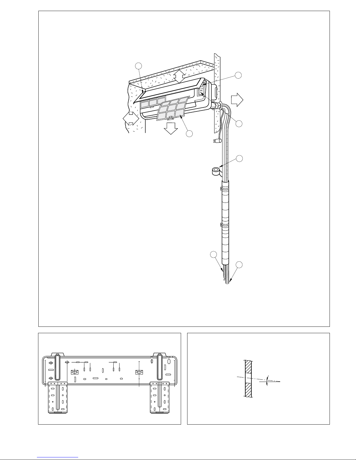
Fig. 1
Fig. 2 Fig. 3
Page 4
4
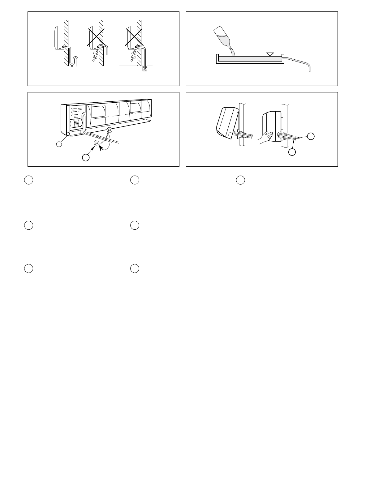
Fig. 4 Fig. 5
1 Panel frontal
Front panel
Panneau frontal
Painel frontal
Pannello frontale
Stirnseite
Frontpanel
2 Interruptor ON/OFF
ON/OFF switch
Interrupteur ON/OFF
Interruptor ON/OFF
Interruttore ON/OFF
EIN/AUS-Schalter
Strömbrytare ON/OFF
3 Tapa de conexiones eléctricas
Wire connection cover plate
Couvercle des connexions électriques
Tampa de conecções eléctricas
Coperchio dell'allacciamento elettrico
Anschlussabdeckung
Skyddskåpa elanslutningar
4 Filtros
Filters
Filtres
Filtros
Filtri
Filter
Filter
5 Cinta vinilo
Vinyl tape
Bande vinyle
Fita de vinilo
Nastro vinilico
Klebeband
Venyltejp
6
Manguera de desagüe
Drain hose
Tuyau de drainage
Mangueira de desaguamento
Tubo scarico condensa
Abflussschlauch
Dräneringsslang
Fig. 6
Fig. 7
7 Cable de interconexión
Interconnecting cable
Câble d'interconnexion
Cabo de interligação
Cavo di collegamento
Verbindungskabel
Anslutningskabel
�
�
5
Modelo / Model / Modèle / Modelo / Modello / Modell /Modell
ERKC-07 AA ERKC-09 AA ERKC-18 AA
Caudal / Flow / Débit / Caudal / Portata / Durchfluss / Luftflöde
(Velocidad alta) / (High speed) / (Grande vitesse) / (Velocidade elevada) /
(Velocità alta) / (Hohe Geschwindigkeit) / (I läget Hög)
m
3
/h 400 400 730
m
3
/s 0,11 0,11 0,20
Control / Control / Contrôle / Controlo / Comando / Steuerung / Styrning Infrarrojos / Infrared rays / Infrarouges / Infravermelhos / Infrarossi / IR / Infraröd strålning
Conexiones frigoríficas / Cooling connections / Raccordements frigorifiques / Ligações frigoríficas / Collegamenti frigoriferi / Kälteanschlüsse / Anslutningar köldmedierör
Diametro mayor / Larger diameter / Le plus diamètre / Diâmetro maior /
Diametro maggiore / Größerer Durchmesser /Större diameter
mm 9,52 (3/8") 9,52 (3/8") 12,5 (1/2")
Diametro menor / Smaller diameter / Le plus petit diamètre / Diâmetro menor
/ Diametro minore / Kleinerer Durchmesser / Mindre diameter
mm 6,35 (1/4") 6,35 (1/4") 6,35 (1/4")
Peso aproximado / Approximate weight / Poids approximatif / Peso aproximado / Peso approssimativo /Ungefähres Gewicht / Ungefärlig vikt
Neto / Nett / Net / Líquido / Netto / Netto / Netto kg 8,5 8,5 13
Bruto / Gross / Brut / Bruto / Lordo / Brutto / Brutto kg 12,5 12,5 16
ERKC-12 AA
490
0,14
12,5 (1/2")
6,35 (1/4")
11
14
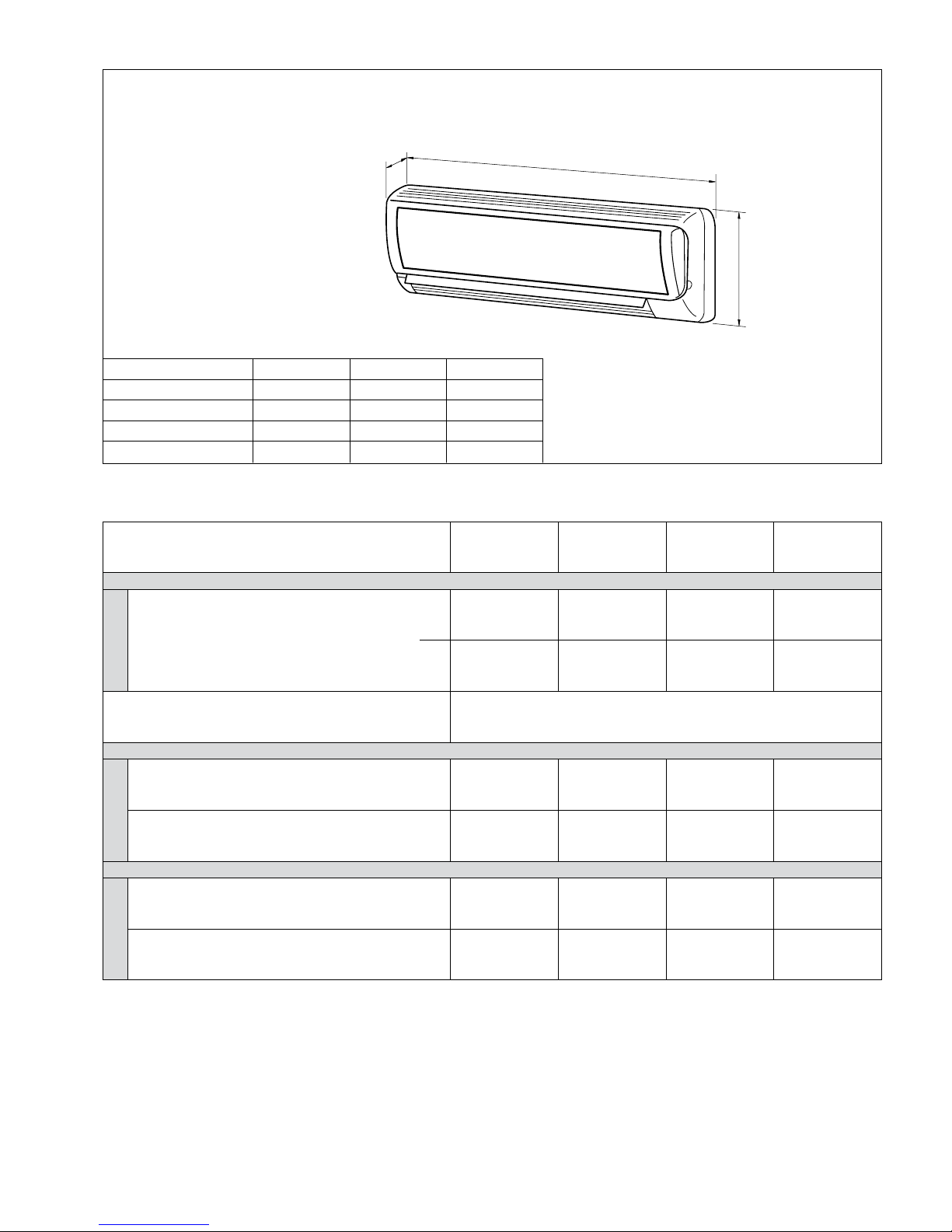
Dimensiones generales / General dimensions mm / Dimensions générales / Dimensões gerais /
Dimensioni d'ingombro / Allgemeine Abmessungen /Allmänna mått
ERKC - 07, 09, 12, 18 AA
Datos físicos / Physical data / Données physiques / Dados físicos / Dati tecnici / Physikalische Angaben /
Fysiska data
C
B
A
A B C
ERKC-07 AA
190 770 250
ERKC-09 AA
190 770 250
ERKC-12 AA
200 830 285
ERKC-18 AA
228 1 020 310
Page 5
5
Modelo / Model / Modèle / Modelo / Modello / Modell /Modell
ERKC-07 AA ERKC-09 AA ERKC-18 AA
Caudal / Flow / Débit / Caudal / Portata / Durchfluss / Luftflöde
(Velocidad alta) / (High speed) / (Grande vitesse) / (Velocidade elevada) /
(Velocità alta) / (Hohe Geschwindigkeit) / (I läget Hög)
m
3
/h 400 400 730
m
3
/s 0,11 0,11 0,20
Control / Control / Contrôle / Controlo / Comando / Steuerung / Styrning Infrarrojos / Infrared rays / Infrarouges / Infravermelhos / Infrarossi / IR / Infraröd strålning
Conexiones frigoríficas / Cooling connections / Raccordements frigorifiques / Ligações frigoríficas / Collegamenti frigoriferi / Kälteanschlüsse / Anslutningar köldmedierör
Diametro mayor / Larger diameter / Le plus diamètre / Diâmetro maior /
Diametro maggiore / Größerer Durchmesser /Större diameter
mm 9,52 (3/8") 9,52 (3/8") 12,5 (1/2")
Diametro menor / Smaller diameter / Le plus petit diamètre / Diâmetro menor
/ Diametro minore / Kleinerer Durchmesser / Mindre diameter
mm 6,35 (1/4") 6,35 (1/4") 6,35 (1/4")
Peso aproximado / Approximate weight / Poids approximatif / Peso aproximado / Peso approssimativo /Ungefähres Gewicht / Ungefärlig vikt
Neto / Nett / Net / Líquido / Netto / Netto / Netto kg 8,5 8,5 13
Bruto / Gross / Brut / Bruto / Lordo / Brutto / Brutto kg 12,5 12,5 16
ERKC-12 AA
490
0,14
12,5 (1/2")
6,35 (1/4")
11
14
Dimensiones generales / General dimensions mm / Dimensions générales / Dimensões gerais /
Dimensioni d'ingombro / Allgemeine Abmessungen /Allmänna mått
ERKC - 07, 09, 12, 18 AA
Datos físicos / Physical data / Données physiques / Dados físicos / Dati tecnici / Physikalische Angaben /
Fysiska data
C
B
A
A B C
ERKC-07 AA
190 770 250
ERKC-09 AA
190 770 250
ERKC-12 AA
200 830 285
ERKC-18 AA
228 1 020 310
Page 6
6
La línea de drenaje debe incluir un codo
(en forma de U) (fig. 4). Conectar un tubo
de drenaje de condensados de plástico con
un diámetro interior de 12 mm.
El tubo de drenaje debe fijarse a las líneas de
refrigeración con cinta de vinilo ver fig. 6.
Instalación típica (fig. 1)
Este dibujo nos muestra, en forma generali-zada, una instalación típica de estos
equipos.
Después de realizar una prueba de drenaje,
aplicar cinta de vinilo ref. 3, uniendo todos
los tubos.
Antes de dar por finalizada la
instalación
Verificar:
- El voltaje está siempre entre
198-254 V.
- La sección de los cables de
alimentación es, como mínimo,
la aconsejada.
- El desagüe de condensados se
realiza perfectamente y no hay
fugas en el circuito de agua.
- Se han dado instrucciones al
usuario para su manejo.
- Se ha informado
de la necesidad de la limpieza periódica del
filtro de aire.
- Se ha cumplimentado la tarjeta
de garantía.
- Se han dado instrucciones de
mantenimiento o efectuado
contrato de revisión periódica.
Instrucciones de
instalación
Inspección
En su recepción, inspeccionar la mercancía y comunicar por escrito las posibles
anomalías al transportista y a la Compañía
de Seguros.
Protección del medio ambiente
Eliminen el embalaje según la
reglamentación vigente para la
preservación del medio ambiente.
Contiene gas fluorado efecto invernadero
cubierto por el protocolo de Kyoto
Para el tipo de gas y la cantidad por sistema
ver la placa de características.
GWP (Global Warming Potential): 2088.
Instalación unidad interior
Fijar la placa de montaje a la pared. Apretar
los tornillos ligeramente.
Nivelar la placa de montaje y a continuación,
apretar los tornillos a fondo. (fig. 2).
Si se sacan las tuberías por la parte poster
ior de la unidad, taladrar un agujero
de diametro 50 mm, en la pared. El lado
exterior del agujero debe estar ligeramente
por debajo del interior, (fig. 3 y 7). Instalar
el pasa muros.
Se pueden instalar las líneas de refrigerante
en diversas posiciones, (fig. 6).
Instalación de las tuberías de interconexión e instalación eléctrica, con la
placa de montaje central ubicada en la
parte posterior del chasis
Colgar la parte superior de la unidad sobre
el panel de montaje y presionarla hacia
delante. Fijar la unidad interior a la placa
de montaje de modo permanente. Doblar
la tubería con cuidado de no aplastarla u
obstruirla.
Pasar la tubería y los cables de la unidad
por el agujero; y colgar la parte superior de
la unidad interior sobre el canto superior de
la placa de montaje, (ver fig. 2).
Asegúrese de que la unidad esté bien colocada, desplazándola primero a la izquierda
y luego a la derecha.
Instrucciones de instalación ERJC-24 DA/28 DA
E
Drenaje de condensados
El tubo de drenaje de la unidad es flexible
y puede colocarse en diversas posiciones.
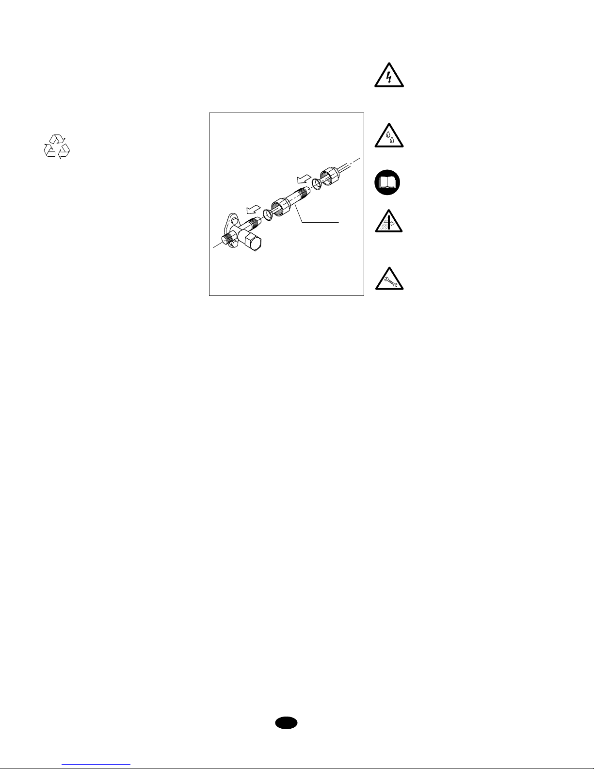
CONVERSOR
Si la combinación de unidades interiores
incluye uno o varios modelos con válvula
de gas de 3/8" se debe instalar el conversor suministrado con la unidad exterior.
Cada unidad exterior dispone de 3
conversores.
Page 7
7
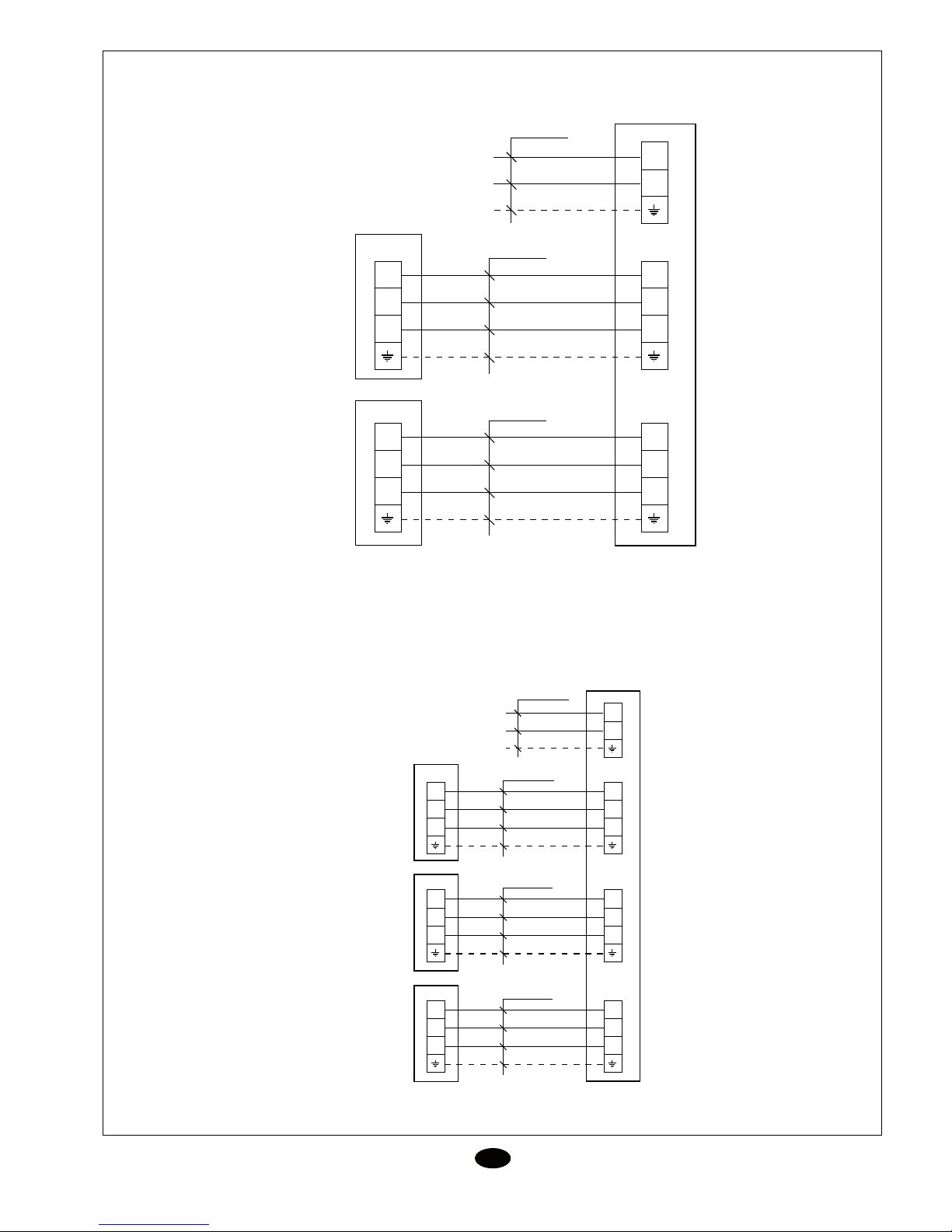
Diagrama de interconexión
E
ERJC - 22DA
ERJC - 24 DA
N
L
3
2
N(1)
3
2
N(1)
3
2
N(1)
3
2
N(1)
4 x 1,5 mm
2
4 x 1,5 mm
2
3 x 4 mm
2
XT
XT
XTB1
XTA1
230V, 1~50Hz
ERJC-22DA
N
L
3
2
N(1)
3
2
N(1)
4 x 1,5 mm
2
3 x 4 mm
2
XT
XTA
3
2
N(1)
3
2
N(1)
4 x 1,5 mm
2
XT
XTB
230V, 1~50Hz
ERJC-24 DA
3
2
N(1)
3
2
N(1)
4 x 1,5 mm
2
XT
XTC
ERKC-07 AA
ERKC-09 AA
ERKC-12 AA
ERKC-07 AA
ERKC-09 AA
ERKC-12 AA
ERKC-07 AA
ERKC-09 AA
ERKC-12 AA
ERKC-07 AA
ERKC-09 AA
ERKC-12 AA
ERKC-18 AA
ERKC-07 AA
ERKC-09 AA
ERKC-12 AA
ERKC-18 AA
ERKC-18 AA
ERKC-18 AA
ERKC-18 AA
Page 8
8
Datos y medidas susceptibles de variación sin previo aviso.
E
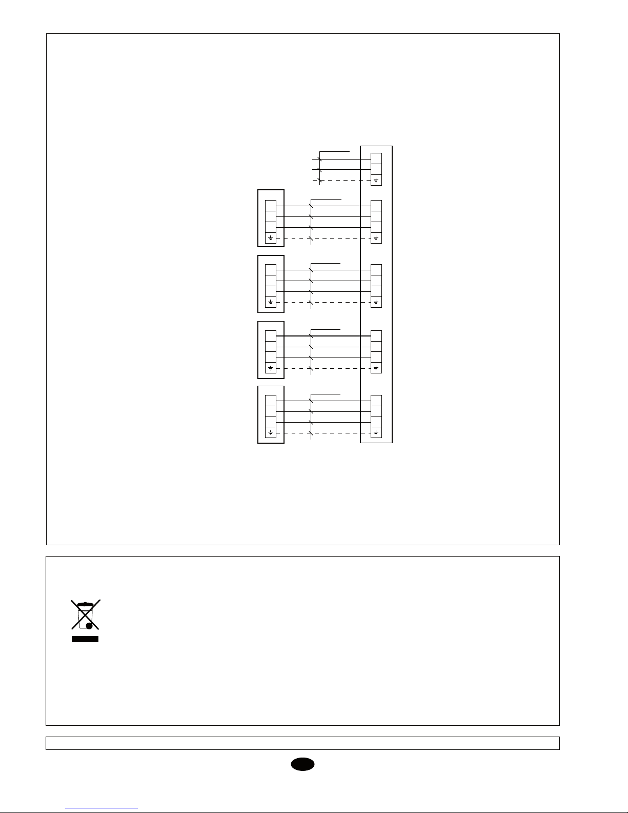
Diagrama de interconexión
N
L
3
2
N(1)
3
2
N(1)
4 x 1,5 mm
2
3 x 4 mm
2
XT
XTA
3
2
N(1)
3
2
N(1)
4 x 1,5 mm
2
XT
XTB
230V, 1~50Hz
ERJC-28 DA
ERKC-07 AA
ERKC-09 AA
ERKC-12 AA
ERKC-07 AA
ERKC-09 AA
ERKC-12 AA
3
2
N(1)
3
2
N(1)
4 x 1,5 mm
2
XT
XTC
ERKC-07 AA
ERKC-09 AA
ERKC-12 AA
3
2
N(1)
3
2
N(1)
4 x 1,5 mm
2
XT
XTD
ERKC-07 AA
ERKC-09 AA
ERKC-12 AA
ERKC-18 AA
ERKC-18 AA
ERKC-18 AA
ERKC-18 AA
Su producto está marcado con este símbolo. Esto significa que al final de su vida útil no debe mezclarse con
el resto de residuos domésticos no clasificados, sino que su eliminación debe realizarse de acuerdo con la
normativa local y nacional pertinente, de forma correcta y respetuosa con el medio ambiente.
El desmantelamiento del acondicionador de aire, así como el tratamiento del refrigerante, aceite y otros
componentes, debe ser efectuado por un instalador competente de acuerdo con la legislación aplicable.
Contacte con las autoridades locales para obtener más información.
ATENCIÓN
ERJC - 28 DA
9
line should include an elbow (U-shaped)
(Fig. 4). Connect a plastic condensed water
drain pipe with a 12 mm. inner diameter.
The drain pipe should be fastened to the
cooling lines with vinyl tape (see Fig. 6).
Typical installation (Fig. 1)
This illustration shows, in general, a typical
installation of this equipment.
After carrying out a drain test, apply vinyl
tape, ref. 3, joining all tubing.
Prior to final approval of the
installation
Check:
- The voltage is always between
198-254 V.
- The power supply cable section
is, at least, that recommended.
- Condensed water drainage is
carried out correctly, and there
are no leaks in the water cir-
cuit.
- Operating instructions have
been given to the user.
- Information has been given on
the need to clean the air filter
periodically.
- The guarantee card has been
filled out.
- Maintenance instructions have
b
een given, or a contract has
been made for periodical servic-
ing.
Installation Instructions
Inspection
Upon reception, inspect the equipment
and notify both the carrier and the insur-
ance company, in writing, of any possible
damage.
Environmental protection
Eliminate packing in accordance
with the regulations in force on
environmental conservation.
Contains greenhouse effect fluorided gas
covered by the Kyoto protocol
For the type of gas and quantity per system,
see the identification plate.
GWP (Global Warming Potential): 2088.
Installation of indoor unit
Fasten the mounting plate to the wall.
Tighten screws slightly. Level the mounting
plate, and then tighten screws to a maximum
(Fig. 2).
If the tubing goes through the back of the
unit, drill a 50 mm. diameter hole in the wall.
The outer
side of this hole should be slightly
below the inner side (Figs. 3 and 7). Install
the through guide.
The refrigerant lines can be installed in dif-
ferent positions (Fig. 6).
Installation of the interconnecting tubing
and wiring, with the central mounting
plate located at the back of the chassis.
Hang the upper part of the unit over the
mounting panel and press forward. Fasten
the indoor unit to the mounting plate per-
manently.
Bend the tubing carefully, without flattening
or obstructing it.
Pass the tubing and cables of the unit
through the hole; and hand the upper part
of the indoor unit on the upper edge of the
mounting plate (see Fig. 2).
Make sure the unit is installed properly,
moving it first to the left and then to the
right.
GB
Installation Instructions
ERJC-24 DA/28 DA
Condensed water drain
The drain pipe of the unit is flexible and can
be placed in different positions. The drain
CONVERTER
If the combination of indoor units includes
one or several with a 3/8" gas valve, the
converter supplied with the outdoor unit
should be installed. Each outdoor unit has
3 converters.
Page 9
9
line should include an elbow (U-shaped)
(Fig. 4). Connect a plastic condensed water
drain pipe with a 12 mm. inner diameter.
The drain pipe should be fastened to the
cooling lines with vinyl tape (see Fig. 6).
Typical installation (Fig. 1)
This illustration shows, in general, a typical
installation of this equipment.
After carrying out a drain test, apply vinyl
tape, ref. 3, joining all tubing.
Prior to final approval of the
installation
Check:
- The voltage is always between
198-254 V.
- The power supply cable section
is, at least, that recommended.
- Condensed water drainage is
carried out correctly, and there
are no leaks in the water circuit.
- Operating instructions have
been given to the user.
- Information has been given on
the need to clean the air filter
periodically.
- The guarantee card has been
filled out.
- Maintenance instructions have
b
een given, or a contract has
been made for periodical servicing.
Installation Instructions
Inspection
Upon reception, inspect the equipment
and notify both the carrier and the insurance company, in writing, of any possible
damage.
Environmental protection
Eliminate packing in accordance
with the regulations in force on
environmental conservation.
Contains greenhouse effect fluorided gas
covered by the Kyoto protocol
For the type of gas and quantity per system,
see the identification plate.
GWP (Global Warming Potential): 2088.
Installation of indoor unit
Fasten the mounting plate to the wall.
Tighten screws slightly. Level the mounting
plate, and then tighten screws to a maximum
(Fig. 2).
If the tubing goes through the back of the
unit, drill a 50 mm. diameter hole in the wall.
The outer
side of this hole should be slightly
below the inner side (Figs. 3 and 7). Install
the through guide.
The refrigerant lines can be installed in different positions (Fig. 6).
Installation of the interconnecting tubing
and wiring, with the central mounting
plate located at the back of the chassis.
Hang the upper part of the unit over the
mounting panel and press forward. Fasten
the indoor unit to the mounting plate permanently.
Bend the tubing carefully, without flattening
or obstructing it.
Pass the tubing and cables of the unit
through the hole; and hand the upper part
of the indoor unit on the upper edge of the
mounting plate (see Fig. 2).
Make sure the unit is installed properly,
moving it first to the left and then to the
right.
GB
Installation Instructions
ERJC-24 DA/28 DA
Condensed water drain
The drain pipe of the unit is flexible and can
be placed in different positions. The drain
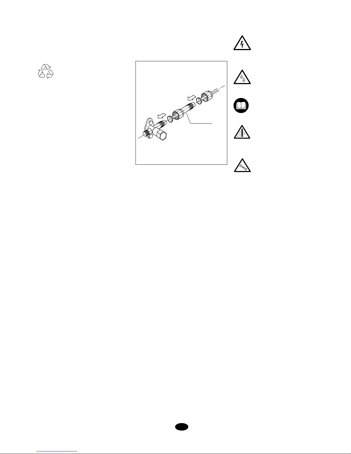
CONVERTER
If the combination of indoor units includes
one or several with a 3/8" gas valve, the
converter supplied with the outdoor unit
should be installed. Each outdoor unit has
3 converters.
Page 10
10
GB
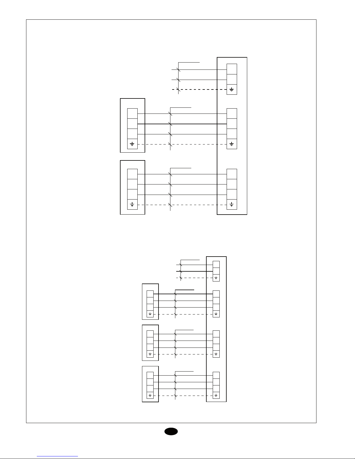
Interconnecting diagram
ERJC-22DA
ERJC-24 DA
N
L
3
2
N(1)
3
2
N(1)
3
2
N(1)
3
2
N(1)
4 x 1,5 mm
2
4 x 1,5 mm
2
3 x 4 mm
2
XT
XT
XTB1
XTA1
230V, 1~50Hz
ERJC-22DA
N
L
3
2
N(1)
3
2
N(1)
4 x 1,5 mm
2
3 x 4 mm
2
XT
XTA
3
2
N(1)
3
2
N(1)
4 x 1,5 mm
2
XT
XTB
230V, 1~50Hz
ERJC-24 DA
3
2
N(1)
3
2
N(1)
4 x 1,5 mm
2
XT
XTC
ERKC-07 AA
ERKC-09 AA
ERKC-12 AA
ERKC-07 AA
ERKC-09 AA
ERKC-12 AA
ERKC-07 AA
ERKC-09 AA
ERKC-12 AA
ERKC-07 AA
ERKC-09 AA
ERKC-12 AA
ERKC-18 AA
ERKC-07 AA
ERKC-09 AA
ERKC-12 AA
ERKC-18 AA
ERKC-18 AA
ERKC-18 AA
ERKC-18 AA
11
Your product is marked with this symbol. This means that at the end of its service life it should not be mixed
with other non-classified household waste. Therefore, disposal should be carried out in compliance with the
corresponding local and national regulations, in a correct and environment-friendly manner.
The dismantling of the air conditioning unit, as well as the processing of refrigerant, oil and other components,
should be carried out by a qualified technician and in compliance with the applicable legislation.
Contact your local authorities for further information
ATTENTION
All data subject to change without notice.
Interconnecting diagram
GB
ERJC-28 DA
N
L
3
2
N(1)
3
2
N(1)
4 x 1,5 mm
2
3 x 4 mm
2
XT
XTA
3
2
N(1)
3
2
N(1)
4 x 1,5 mm
2
XT
XTB
230V, 1~50Hz
ERJC-28 DA
3
2
N(1)
3
2
N(1)
4 x 1,5 mm
2
XT
XTC
3
2
N(1)
3
2
N(1)
4 x 1,5 mm
2
XT
XTD
ERKC-07 AA
ERKC-09 AA
ERKC-12 AA
ERKC-07 AA
ERKC-09 AA
ERKC-12 AA
ERKC-07 AA
ERKC-09 AA
ERKC-12 AA
ERKC-07 AA
ERKC-09 AA
ERKC-12 AA
ERKC-18 AA
ERKC-18 AA
ERKC-18 AA
ERKC-18 AA
Page 11
11
Your product is marked with this symbol. This means that at the end of its service life it should not be mixed
with other non-classified household waste. Therefore, disposal should be carried out in compliance with the
corresponding local and national regulations, in a correct and environment-friendly manner.
The dismantling of the air conditioning unit, as well as the processing of refrigerant, oil and other components,
should be carried out by a qualified technician and in compliance with the applicable legislation.
Contact your local authorities for further information
ATTENTION
All data subject to change without notice.
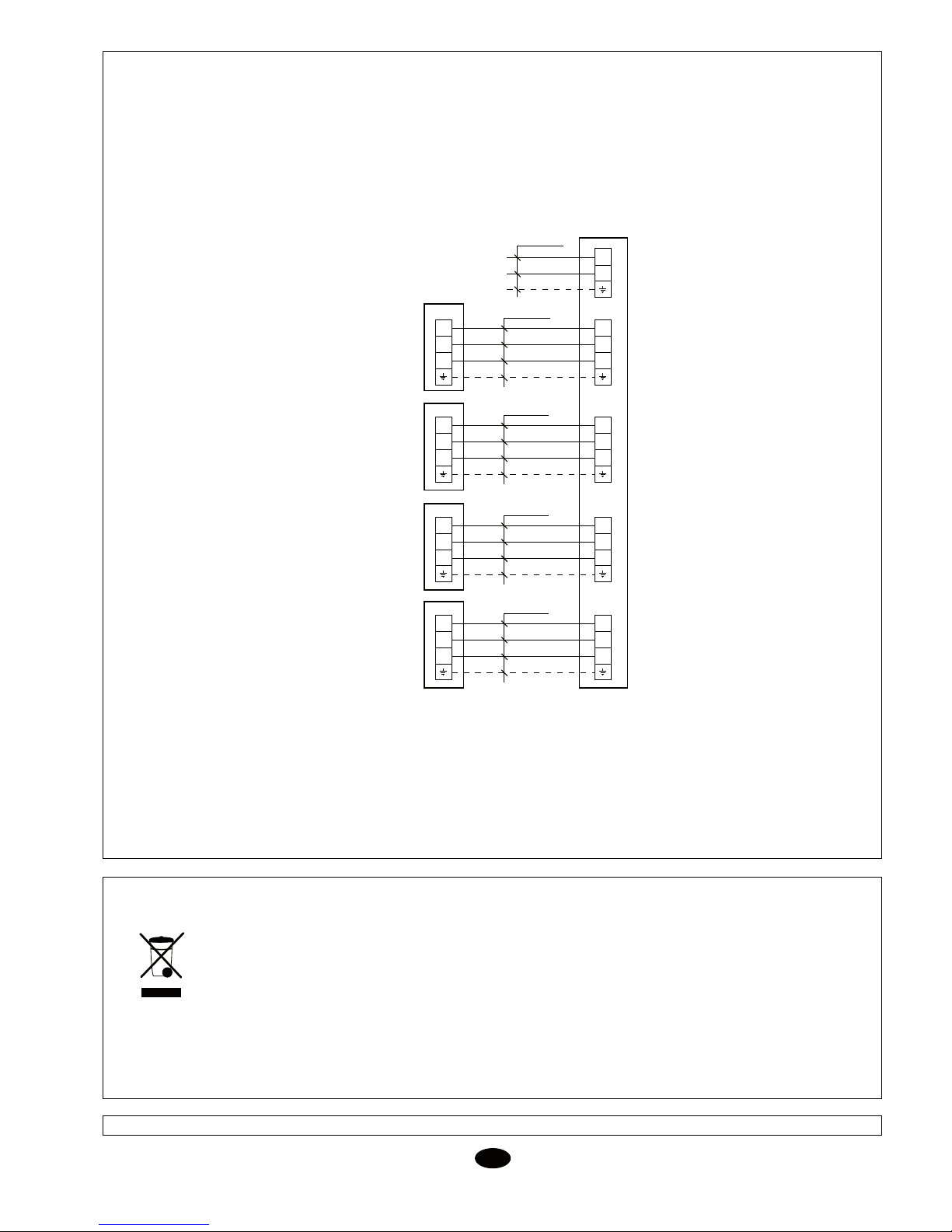
Interconnecting diagram
GB
ERJC-28 DA
N
L
3
2
N(1)
3
2
N(1)
4 x 1,5 mm
2
3 x 4 mm
2
XT
XTA
3
2
N(1)
3
2
N(1)
4 x 1,5 mm
2
XT
XTB
230V, 1~50Hz
ERJC-28 DA
3
2
N(1)
3
2
N(1)
4 x 1,5 mm
2
XT
XTC
3
2
N(1)
3
2
N(1)
4 x 1,5 mm
2
XT
XTD
ERKC-07 AA
ERKC-09 AA
ERKC-12 AA
ERKC-07 AA
ERKC-09 AA
ERKC-12 AA
ERKC-07 AA
ERKC-09 AA
ERKC-12 AA
ERKC-07 AA
ERKC-09 AA
ERKC-12 AA
ERKC-18 AA
ERKC-18 AA
ERKC-18 AA
ERKC-18 AA
Page 12
12
F
Instructions d’installation
Inspection
Au moment de sa réception, vérifier la
marchandise et communiquer par écrit les
possibles anomalies au transporteur et à la
compagnie d’assurances.
Protection de l’environnement
L’élimination de l’emballage doit
s’effectuer conformément à la
réglementation en vigueur pour la
préservation de l’environnement.
Il contient du gaz fluoré à effet de serre
couvert par le protocole de Kyoto.
Pour le type de gaz et la quantité par système, voir la plaque des caractéristiques.
GWP (Global Warming Potential): 2088.
Installation de l’unité inté-
rieure
Fixer la plaque de montage au mur. Serrer
légèrement les vis.
Mettre la plaque de montage à niveau et
ensuite serrer les vis à fond. (fig.2).
Si la tuyauterie sort de la partie postérieure
de l’unité, percer un trou de 50 mm de diamètre dans le mur. Le côté extérieur du trou
doit être légèrement au-dessous du côté
intérieur (fig.3 et 7). Installer le passe-fils.
Il est possib
le d’installer les lignes de réfrigé-
rant dans différentes positions. (fig.6).
Installation de la tuyauterie d’interconnexion et installation électrique, avec la
plaque de montage centrale située dans
la partie postérieure du châssis.
Accrocher la partie supérieure de l’unité sur
le panneau de montage et exercer une pression vers l’avant. Fixer l’unité intérieure à la
plaque de montage de façon permanente.
Introduire la tuyauterie en faisant attention
à ne pas l’aplatir ou l’obstruer.
Faire passer la tuyauterie et les fils de l’unité
dans le trou et accrocher la partie supérieure
de l’unité intérieure sur le bord supérieur de
la plaque de montage (voir fig.2).
S’assurer que l’unité est bien installée, en
la déplaçant tout d’abord vers la gauche et
ensuite vers la droite.
Instructions d’installation
ERJC-24 DA/28DA
Drainage de condensats
Le tuyau de drainage de l’unité est flexible
et peut être placé dans plusieurs positions.
La ligne de drainage d
oit inclure un code (en
forme de U)(fig.4). Connecter un tuyau de
drainage de condensats en plastique d’un
diamètre intérieur de 12 mm.
Le tuyau de drainage doit être fixé aux lignes
de refroidissement avec une bande vinyle.
(voir fig.6)
Installation typique (fig.1)
Ce dessin nous montre une installation
typique de ces appareils.
Après avoir réalisé un essai de drainage,
appliquer la bande vinyle réf.3 en unissant
tous les tuyaux.
Avant de considérer
l’installation terminée
Vérifier que:
- Le voltage est toujours entre
198 et 254 V.
- La section des fils d’alimentation est au minimum celle qui
est recommandée.
- Le drain des condensats s’effectue parfaitement et qu’il n’y
a pas de fuites dans le circuit
d’eau.
- Des instructions d’utilisation
ont été données à l’utilisateur.
- L’utilisateur a été informé de la
nécessité du nettoyage périodique du filtre à air.
- La carte de garantie a été dûment remplie.
- Des instructions
de maintenance ont été données ou un
contrat de révision périodique
a été établi.
CONVERTISSEUR
Si la combinaison d’unités intérieures
inclut un ou plusieurs modèles avec vanne
de gaz de 3/8’’, il faut installer le convertisseur fourni avec l’unité extérieure.
Chaque unité extérieure dispose de 3
convertisseurs.
Page 13
13
F
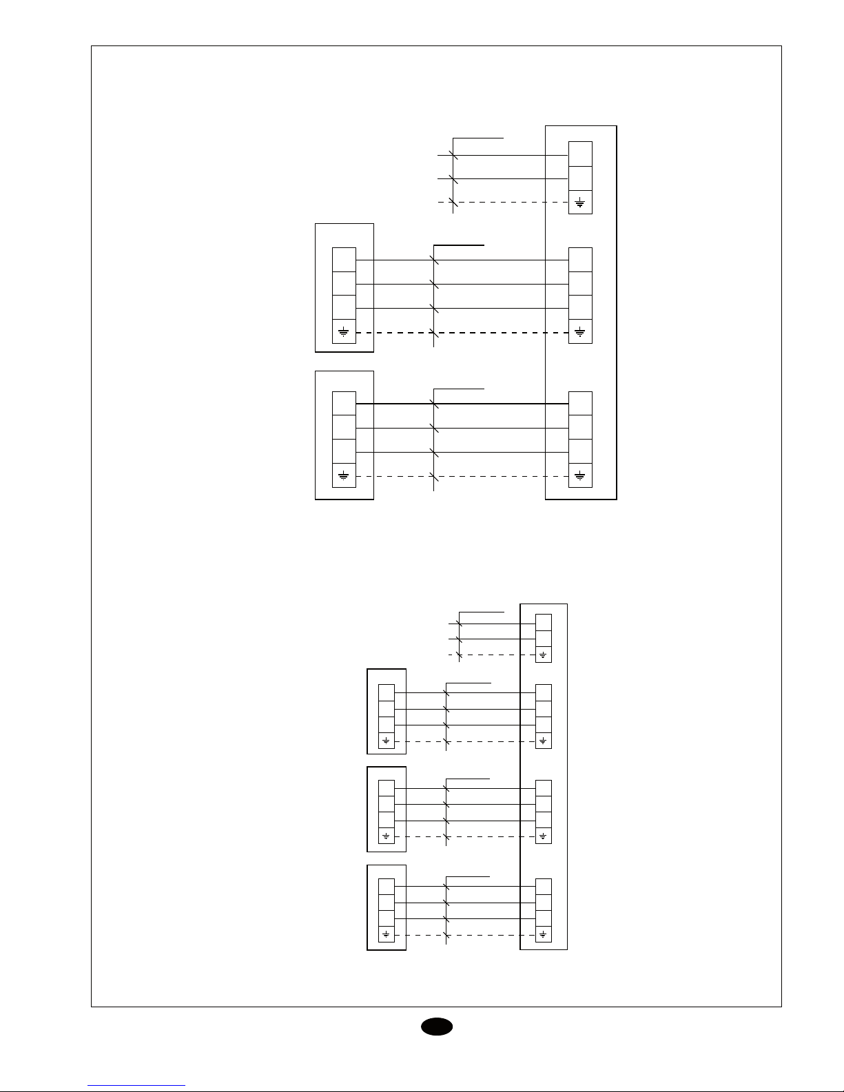
Schéma d’interconnexion
ERJC - 22 DA
ERJC - 24 DA
N
L
3
2
N(1)
3
2
N(1)
3
2
N(1)
3
2
N(1)
4 x 1,5 mm
2
4 x 1,5 mm
2
3 x 4 mm
2
XT
XT
XTB1
XTA1
230V, 1~50Hz
ERJC-22DA
N
L
3
2
N(1)
3
2
N(1)
4 x 1,5 mm
2
3 x 4 mm
2
XT
XTA
3
2
N(1)
3
2
N(1)
4 x 1,5 mm
2
XT
XTB
230V, 1~50Hz
ERJC-24 DA
3
2
N(1)
3
2
N(1)
4 x 1,5 mm
2
XT
XTC
ERKC-07 AA
ERKC-09 AA
ERKC-12 AA
ERKC-07 AA
ERKC-09 AA
ERKC-12 AA
ERKC-07 AA
ERKC-09 AA
ERKC-12 AA
ERKC-07 AA
ERKC-09 AA
ERKC-12 AA
ERKC-18 AA
ERKC-07 AA
ERKC-09 AA
ERKC-12 AA
ERKC-18 AA
ERKC-18 AA
ERKC-18 AA
ERKC-18 AA
Page 14
14
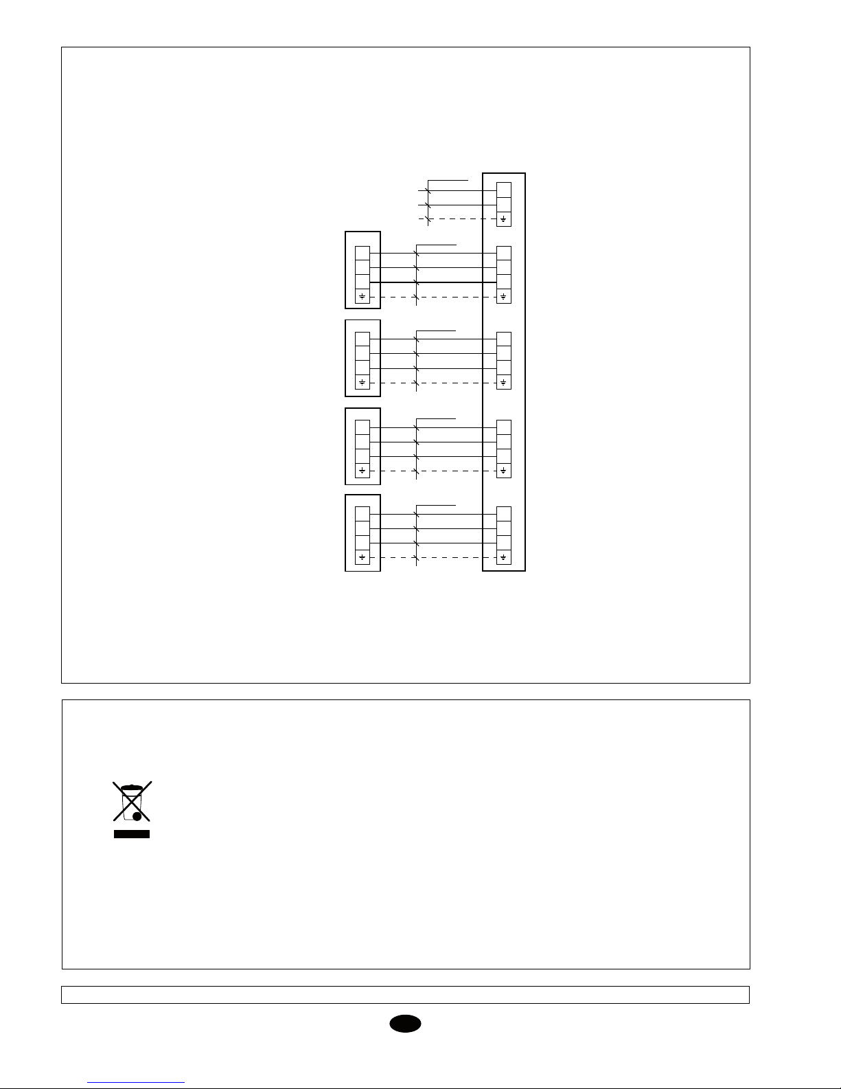
Schéma d’interconnexion
ERJC - 28 DA
F
ATTENTION
Ce produit porte ce symbole. Cela signifie qu’à la fin de sa vie utile, il ne devra pas être jeté avec
les autres déchets domestiques non classés. Son élimination devra être réalisée conformément
à la réglementation locale et nationale en vigueur, de manière correcte et respectueuse de
l’environnement.
Le démantèlement du climatiseur, ainsi que le traitement du réfrigérant, de l’huile et des autres
composants doivent être effectués par un installateur compétent, conformément à la législation
applicable.
Contacter les autorités locales pour obtenir toute information supplémentaire.
Données et mesures susceptibles de variation sans préavis.
N
L
3
2
N(1)
3
2
N(1)
4 x 1,5 mm
2
3 x 4 mm
2
XT
XTA
3
2
N(1)
3
2
N(1)
4 x 1,5 mm
2
XT
XTB
230V, 1~50Hz
ERJC-28 DA
3
2
N(1)
3
2
N(1)
4 x 1,5 mm
2
XT
XTC
3
2
N(1)
3
2
N(1)
4 x 1,5 mm
2
XT
XTD
ERKC-07 AA
ERKC-09 AA
ERKC-12 AA
ERKC-07 AA
ERKC-09 AA
ERKC-12 AA
ERKC-07 AA
ERKC-09 AA
ERKC-12 AA
ERKC-07 AA
ERKC-09 AA
ERKC-12 AA
ERKC-18 AA
ERKC-18 AA
ERKC-18 AA
ERKC-18 AA
15
linha de drenagem deve incluir um cotovelo
(em forma de U) (Fig. 4). Há que ligar um
tubo de drenagem de condensados de plás-
tico com um diâmetro interior de 12 mm.
O tubo de drenagem dos condensados deve
ser fixado às linhas de refrigeração por meio
de fita de vinil (vejase a Fig. 6).
Instalação típica (Fig. 1)
Este desenho mostra, de forma gene-
ralizada, uma instalação típica de estes
equipamentos.
Depois de ter realizado um teste de dre-
nagem, há que aplicar fita de vinil (refª 3),
unindo todos os tubos.
Antes de dar por finalizada a
instalação
Verificar se:
- A voltagem se encontra sempre
entre 198-254 V.
- A secção dos cabos de alimen-
tação é, no mínimo, a aconse-
lhada.
- O desaguamento de condensa-
dos se realiza perfeitamente e
que não hajam fugas no circuito
de água.
- Ao utente lhe foram dadas ins-
truções para a sua utilização.
- Ele foi informado da necessida-
de da limpeza periódica do filtro
de ar.
- Ele preencheu o cartão de ga-
rantia.
- Lhe foram dadas as instruções
de manutenção ou efectuado
um contrato de revisão periódi-
ca.
Instruções de Instalação
Inspecção
À sua recepção, há que inspeccionar a mer-
cadoria e comunicar as possíveis anomalias
por escrito ao transportador e à Companhia
de Seguros.
Protecção do meio ambiente
Deve-se eliminar a embalagem de
acordo com a regulamentação para
a preservação do meio ambiente
em vigor.
Contém gás fluorado com efeito de estu-
fa coberto pelo protocolo de Kyoto
Para o tipo de gás e a quantidade por siste-
ma, ver a placa de características
GWP (Global Warming Potential): 2088.
Instalação da unidade interior
Fixar a placa de montagem à parede. Aper-
tar ligeiramente os parafusos.
Nivelar a placa de montagem e, a
seguir,
apertar a fundo os parafusos (Fig. 2).
Se as tubagens saírem pela parte traseira
da unidade, há que perfurar na parede um
orifício de 50 mm de diâmetro. O lado exte-
rior do orifício deve encontrar-se a um nível
ligeiramente inferior ao do lado interior (Figs.
3 e 7). Há que instalar o passa-muros.
Podem-se instalar as linhas de refrigerante
em diversas posições (Fig. 6).
Instalação das tubagens de interligação
e de instalação eléctrica, com a placa
de montagem central situada na parte
traseira do chassis
Pendurar a parte superior da unidade sobre
o painel de montagem e pressioná-la para
a frente. Fixar a unidade interior à placa de
montagem de um modo permanente. Do-
brar a tubagem com cuidado a fim de não
amachucá-la ou de não obstruí-la.
Passar a tubagem e os cabos da unidade
através do orifício; depois pendurar a parte
superior da unidade interior sobre o canto
superior da
placa de montagem (veja-se
a Fig. 2).
Há que certificar-se de que a unidade esteja
bem colocada, deslocando-a em primeiro
lugar para a esquerda e logo a seguir para
a direita.
P
Instructions d’installation
ERJC-24 DA/28 DA
Drenagem de condensados
O tubo de drenagem da unidade é flexível
e pode-se colocar em diversas posições. A
CONVERSOR
Se a combinação de unidades interiores
inclui um ou vários modelos com válvula
de gás de 3/8", deve instalar-se o conver-
sor fornecido junto com a unidade
exterior. Cada unidade exterior dispõe de
3 conversores.
Page 15
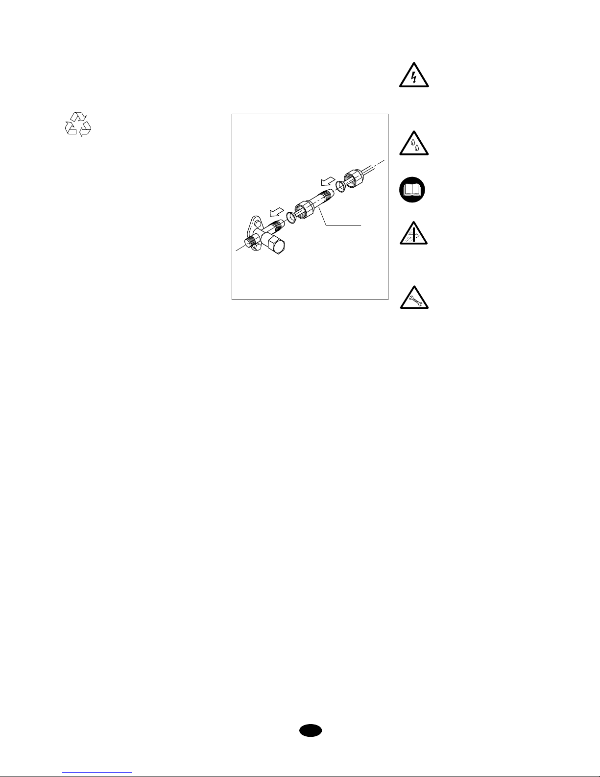
15
linha de drenagem deve incluir um cotovelo
(em forma de U) (Fig. 4). Há que ligar um
tubo de drenagem de condensados de plástico com um diâmetro interior de 12 mm.
O tubo de drenagem dos condensados deve
ser fixado às linhas de refrigeração por meio
de fita de vinil (vejase a Fig. 6).
Instalação típica (Fig. 1)
Este desenho mostra, de forma generalizada, uma instalação típica de estes
equipamentos.
Depois de ter realizado um teste de drenagem, há que aplicar fita de vinil (refª 3),
unindo todos os tubos.
Antes de dar por finalizada a
instalação
Verificar se:
- A voltagem se encontra sempre
entre 198-254 V.
- A secção dos cabos de alimentação é, no mínimo, a aconselhada.
- O desaguamento de condensados se realiza perfeitamente e
que não hajam fugas no circuito
de água.
- Ao utente lhe foram dadas instruções para a sua utilização.
- Ele foi informado da necessidade da limpeza periódica do filtro
de ar.
- Ele preencheu o cartão de garantia.
- Lhe foram dadas as instruções
de manutenção ou efectuado
um contrato de revisão periódica.
Instruções de Instalação
Inspecção
À sua recepção, há que inspeccionar a mercadoria e comunicar as possíveis anomalias
por escrito ao transportador e à Companhia
de Seguros.
Protecção do meio ambiente
Deve-se eliminar a embalagem de
acordo com a regulamentação para
a preservação do meio ambiente
em vigor.
Contém gás fluorado com efeito de estu-
fa coberto pelo protocolo de Kyoto
Para o tipo de gás e a quantidade por sistema, ver a placa de características
GWP (Global Warming Potential): 2088.
Instalação da unidade interior
Fixar a placa de montagem à parede. Apertar ligeiramente os parafusos.
Nivelar a placa de montagem e, a
seguir,
apertar a fundo os parafusos (Fig. 2).
Se as tubagens saírem pela parte traseira
da unidade, há que perfurar na parede um
orifício de 50 mm de diâmetro. O lado exterior do orifício deve encontrar-se a um nível
ligeiramente inferior ao do lado interior (Figs.
3 e 7). Há que instalar o passa-muros.
Podem-se instalar as linhas de refrigerante
em diversas posições (Fig. 6).
Instalação das tubagens de interligação
e de instalação eléctrica, com a placa
de montagem central situada na parte
traseira do chassis
Pendurar a parte superior da unidade sobre
o painel de montagem e pressioná-la para
a frente. Fixar a unidade interior à placa de
montagem de um modo permanente. Dobrar a tubagem com cuidado a fim de não
amachucá-la ou de não obstruí-la.
Passar a tubagem e os cabos da unidade
através do orifício; depois pendurar a parte
superior da unidade interior sobre o canto
superior da
placa de montagem (veja-se
a Fig. 2).
Há que certificar-se de que a unidade esteja
bem colocada, deslocando-a em primeiro
lugar para a esquerda e logo a seguir para
a direita.
P
Instructions d’installation
ERJC-24 DA/28 DA
Drenagem de condensados
O tubo de drenagem da unidade é flexível
e pode-se colocar em diversas posições. A
CONVERSOR
Se a combinação de unidades interiores
inclui um ou vários modelos com válvula
de gás de 3/8", deve instalar-se o conversor fornecido junto com a unidade
exterior. Cada unidade exterior dispõe de
3 conversores.
Page 16
16
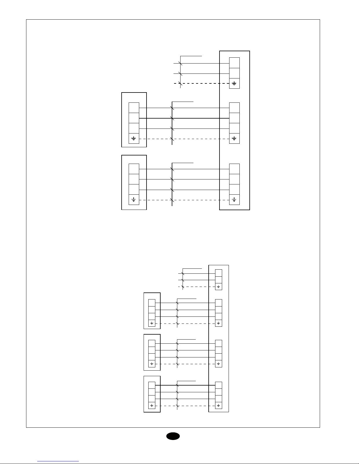
Diagrama de interligação
P
ERJC-22 DA
ERJC-24 DA
N
L
3
2
N(1)
3
2
N(1)
3
2
N(1)
3
2
N(1)
4 x 1,5 mm
2
4 x 1,5 mm
2
3 x 4 mm
2
XT
XT
XTB1
XTA1
230V, 1~50Hz
ERJC-22DA
N
L
3
2
N(1)
3
2
N(1)
4 x 1,5 mm
2
3 x 4 mm
2
XT
XTA
3
2
N(1)
3
2
N(1)
4 x 1,5 mm
2
XT
XTB
230V, 1~50Hz
ERJC-24 DA
3
2
N(1)
3
2
N(1)
4 x 1,5 mm
2
XT
XTC
ERKC-07 AA
ERKC-09 AA
ERKC-12 AA
ERKC-07 AA
ERKC-09 AA
ERKC-12 AA
ERKC-07 AA
ERKC-09 AA
ERKC-12 AA
ERKC-07 AA
ERKC-09 AA
ERKC-12 AA
ERKC-18 AA
ERKC-07 AA
ERKC-09 AA
ERKC-12 AA
ERKC-18 AA
ERKC-18 AA
ERKC-18 AA
ERKC-18 AA
17
Dados e medidas susceptíveis de variação sem aviso prévio.
P
O seu produto encontra-se marcado com este símbolo. Isto significa que no fim da sua vida útil não deve
ser misturado com o resto de resíduos domésticos não classificados, senão que a sua eliminação deve ser
realizada de acordo com a normativa local e nacional correspondente, de uma forma correcta e respeitosa
com o meio ambiente.
A desmontagem do condicionador de ar, bem como o tratamento do refrigerante, do óleo e doutros compo-
nentes, deve ser efectuado por um instalador qualificado de acordo com a legislação aplicável.
Contacte as autoridades locais para obter mais informação.
ATENÇÃO
Diagrama de interligação
ERJC-28 DA
N
L
3
2
N(1)
3
2
N(1)
4 x 1,5 mm
2
3 x 4 mm
2
XT
XTA
3
2
N(1)
3
2
N(1)
4 x 1,5 mm
2
XT
XTB
230V, 1~50Hz
ERJC-28 DA
3
2
N(1)
3
2
N(1)
4 x 1,5 mm
2
XT
XTC
3
2
N(1)
3
2
N(1)
4 x 1,5 mm
2
XT
XTD
ERKC-07 AA
ERKC-09 AA
ERKC-12 AA
ERKC-07 AA
ERKC-09 AA
ERKC-12 AA
ERKC-07 AA
ERKC-09 AA
ERKC-12 AA
ERKC-07 AA
ERKC-09 AA
ERKC-12 AA
ERKC-18 AA
ERKC-18 AA
ERKC-18 AA
ERKC-18 AA
Page 17
17
Dados e medidas susceptíveis de variação sem aviso prévio.
P
O seu produto encontra-se marcado com este símbolo. Isto significa que no fim da sua vida útil não deve
ser misturado com o resto de resíduos domésticos não classificados, senão que a sua eliminação deve ser
realizada de acordo com a normativa local e nacional correspondente, de uma forma correcta e respeitosa
com o meio ambiente.
A desmontagem do condicionador de ar, bem como o tratamento do refrigerante, do óleo e doutros componentes, deve ser efectuado por um instalador qualificado de acordo com a legislação aplicável.
Contacte as autoridades locais para obter mais informação.
ATENÇÃO
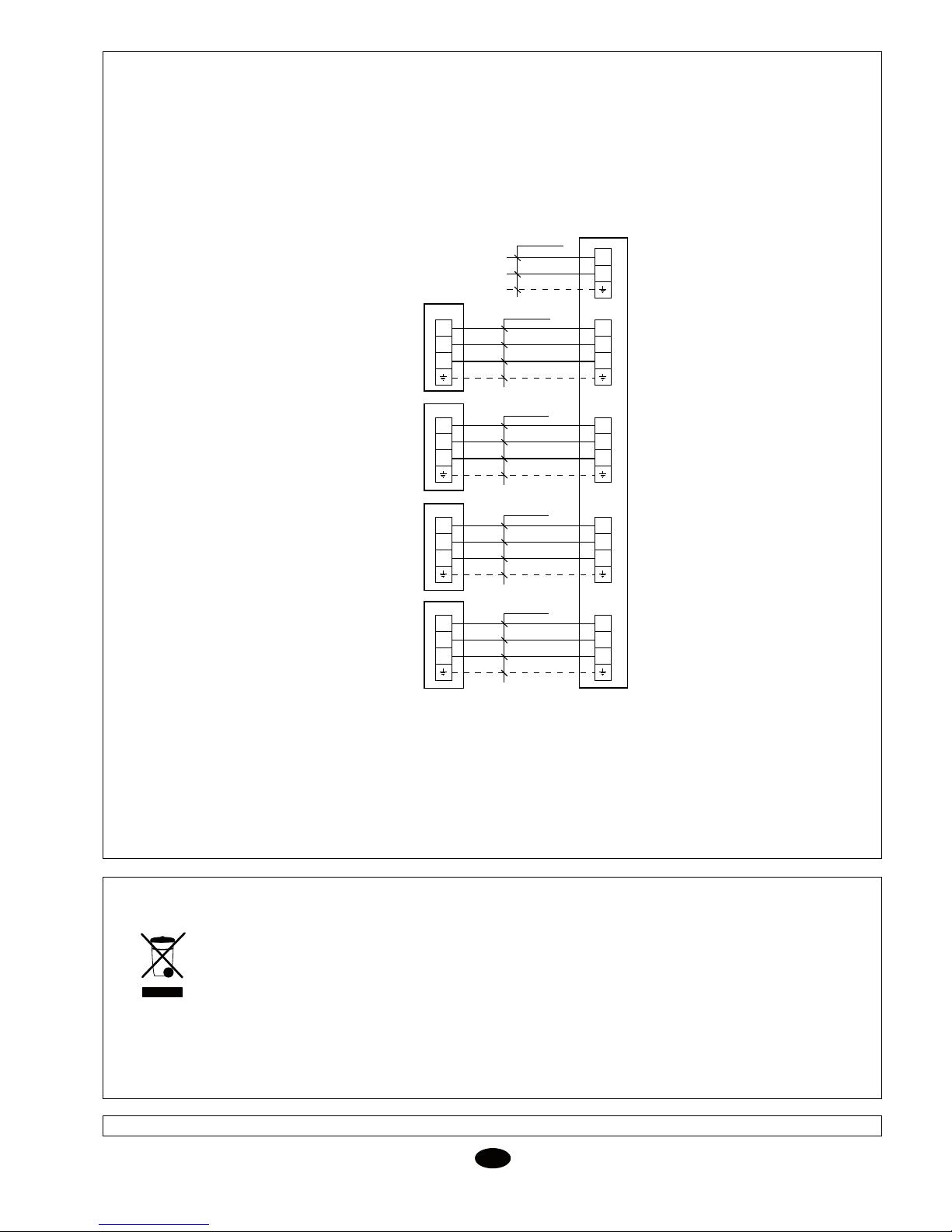
Diagrama de interligação
ERJC-28 DA
N
L
3
2
N(1)
3
2
N(1)
4 x 1,5 mm
2
3 x 4 mm
2
XT
XTA
3
2
N(1)
3
2
N(1)
4 x 1,5 mm
2
XT
XTB
230V, 1~50Hz
ERJC-28 DA
3
2
N(1)
3
2
N(1)
4 x 1,5 mm
2
XT
XTC
3
2
N(1)
3
2
N(1)
4 x 1,5 mm
2
XT
XTD
ERKC-07 AA
ERKC-09 AA
ERKC-12 AA
ERKC-07 AA
ERKC-09 AA
ERKC-12 AA
ERKC-07 AA
ERKC-09 AA
ERKC-12 AA
ERKC-07 AA
ERKC-09 AA
ERKC-12 AA
ERKC-18 AA
ERKC-18 AA
ERKC-18 AA
ERKC-18 AA
Page 18
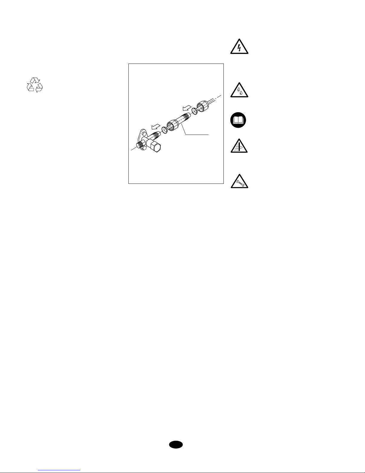
18
I
Istruzioni per l’installazione
Controllo
Al ricevimento, controllare la merce e comunicare per iscritto al vettore e alla compagnia
assicuratrice le anomalie eventualmente
riscontrate.
Ecologia
Eliminare l’imballo attenendosi alla
normativa vigente per la raccolta
selettiva dei rifiuti e la tutela dell’ambiente.
Contiene gas fluorurato ad effetto serra
contemplato dal Protocollo di Kyoto.
Per il tipo di gas e la quantità contenuta nel
sistema, vedi piastrina delle caratteristiche.
GWP (Global Warming Potential): 2088.
Installazione dell’unità interna
Fissare la piastra d’installazione alla parete,
serrandone appena le viti.
Livellare la piastra d’installazione, quindi
serrare bene le viti (Fig. 2).
Se i tubi vengono fatti uscire dalla parte
posteriore dell’unità, realizzare nella parete
un foro di 50 mm di diametro, leggermente
inclinato verso l’esterno (Figg. 3
e 7). Installare nel muro una guida per il passaggio
dei tubi.
I tubi del circuito frigorifero possono essere
installati in diverse posizioni (Fig. 6).
Installazione dei tubi di collegamento e
dell’allacciamento elettrico, con la piastra
d’installazione centrale ubicata nella
parte posteriore della struttura
Appendere la parte superiore dell’unità alla
piastra d’installazione e premere in avanti.
Fissare bene l’unità interna alla piastra d’installazione. Piegare il tubo con cura, facendo
attenzione a non schiacciarlo od ostruirlo.
Far passare i tubi e i cavi dell’unità per il foro
e appendere la parte superiore dell’unità
interna sul bordo superiore della piastra
d’installazione (Fig. 2).
Accertarsi che l’unità sia ben collocata, spostandola prima a destra e poi a sinistra.
La linea di scarico condensa deve in
cludere
un raccordo a gomito (a forma di U) (Fig.
4). Collegare un tubo di scarico condensa
di plastica con un diametro interno di 12
mm. Il tubo di scarico condensa deve essere fissato alle linee frigorifere con nastro
vinilico (Fig. 6).
Installazione tipica (Fig. 1)
Nella figura viene illustrata, in modo generico, un’installazione tipica di questi
apparecchi.
Dopo aver realizzato una prova dello scarico
condensa, unire tutti i tubi con nastro vinilico
(item 5).
Prima di considerare ultimata
l’installazione
Verificare:
- Che il voltaggio si trovi sempre
tra 198 e 254 V.
- Che la sezione dei cavi di alimentazione sia almeno pari a
quella consigliata negli schemi
elettrici corrispondenti.
- Che lo scarico della condensa
avvenga perfettamente e che
non ci siano perdite nel circuito
dell’acqua.
- Di a
ver dato all’utente le istru-
zioni per l’uso.
- Di averlo informato sulla necessità di pulire periodicamente il filtro dell’aria.
- Di aver compilato il certificato
di garanzia.
- Di aver dato le oppor tune
istruzioni per la manutenzione
o stipulato un contratto di revisione periodica.
Istruzioni per l’installazione
di unità ERJC-24 DA/28 DA
Scarico condensa
Il tubo di scarico condensa dell’unità è
flessibile e può essere collocato in diverse
posizioni.
ADATTATORE
Se la combinazione di unità interne
include uno o più modelli con valvole del
gas da 3/8”, si deve installare l’adattatore
fornito con l’unità esterna. Con ogni unità
esterna vengono forniti 3 adattatori.
19
I
Schema di collegamento tra le unità
ERJC-22 DA
ERJC-24 DA
N
L
3
2
N(1)
3
2
N(1)
3
2
N(1)
3
2
N(1)
4 x 1,5 mm
2
4 x 1,5 mm
2
3 x 4 mm
2
XT
XT
XTB1
XTA1
230V, 1~50Hz
ERJC-22DA
N
L
3
2
N(1)
3
2
N(1)
4 x 1,5 mm
2
3 x 4 mm
2
XT
XTA
3
2
N(1)
3
2
N(1)
4 x 1,5 mm
2
XT
XTB
230V, 1~50Hz
ERJC-24 DA
3
2
N(1)
3
2
N(1)
4 x 1,5 mm
2
XT
XTC
ERKC-07 AA
ERKC-09 AA
ERKC-12 AA
ERKC-07 AA
ERKC-09 AA
ERKC-12 AA
ERKC-07 AA
ERKC-09 AA
ERKC-12 AA
ERKC-07 AA
ERKC-09 AA
ERKC-12 AA
ERKC-18 AA
ERKC-07 AA
ERKC-09 AA
ERKC-12 AA
ERKC-18 AA
ERKC-18 AA
ERKC-18 AA
ERKC-18 AA
Page 19
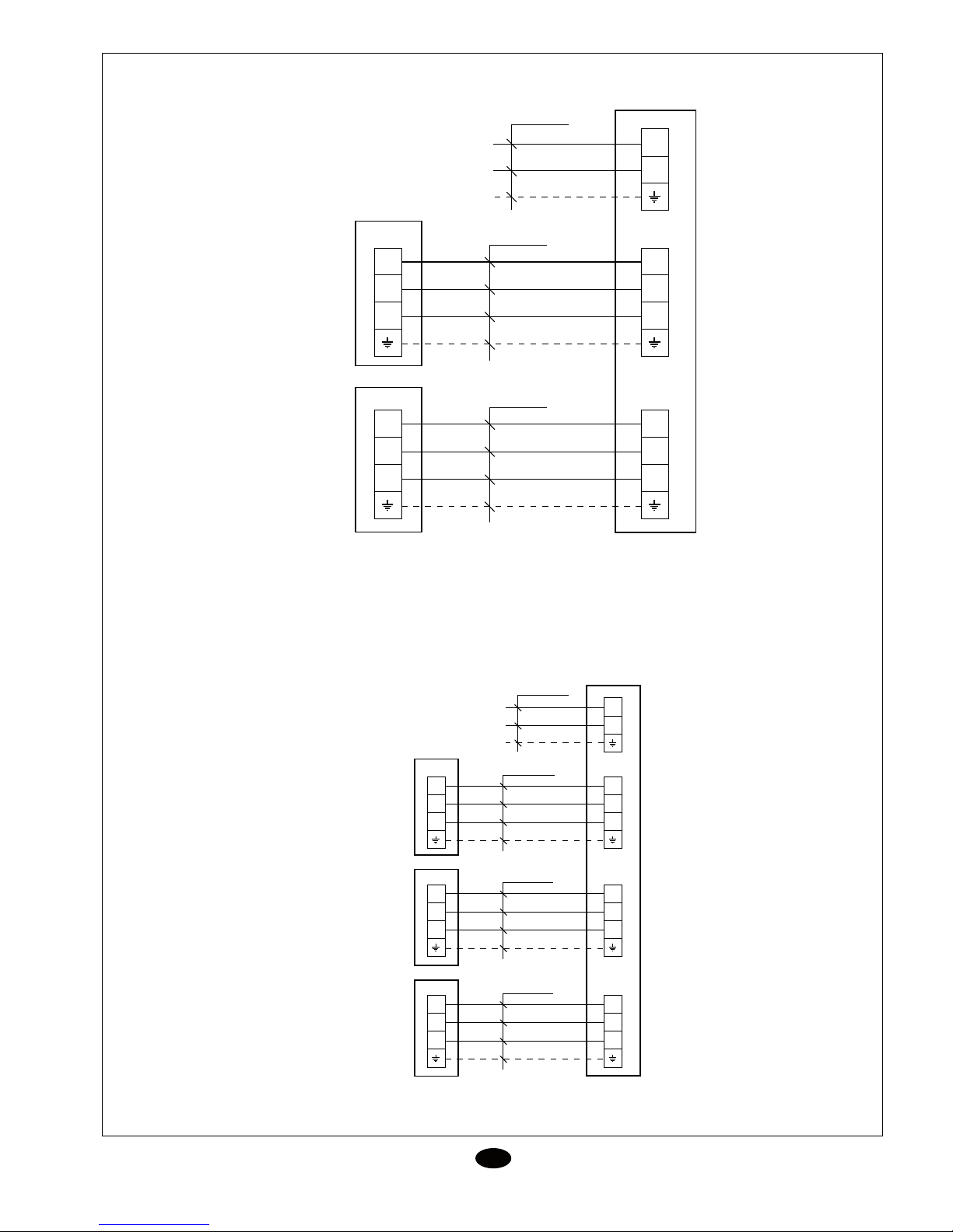
19
I
Schema di collegamento tra le unità
ERJC-22 DA
ERJC-24 DA
N
L
3
2
N(1)
3
2
N(1)
3
2
N(1)
3
2
N(1)
4 x 1,5 mm
2
4 x 1,5 mm
2
3 x 4 mm
2
XT
XT
XTB1
XTA1
230V, 1~50Hz
ERJC-22DA
N
L
3
2
N(1)
3
2
N(1)
4 x 1,5 mm
2
3 x 4 mm
2
XT
XTA
3
2
N(1)
3
2
N(1)
4 x 1,5 mm
2
XT
XTB
230V, 1~50Hz
ERJC-24 DA
3
2
N(1)
3
2
N(1)
4 x 1,5 mm
2
XT
XTC
ERKC-07 AA
ERKC-09 AA
ERKC-12 AA
ERKC-07 AA
ERKC-09 AA
ERKC-12 AA
ERKC-07 AA
ERKC-09 AA
ERKC-12 AA
ERKC-07 AA
ERKC-09 AA
ERKC-12 AA
ERKC-18 AA
ERKC-07 AA
ERKC-09 AA
ERKC-12 AA
ERKC-18 AA
ERKC-18 AA
ERKC-18 AA
ERKC-18 AA
Page 20
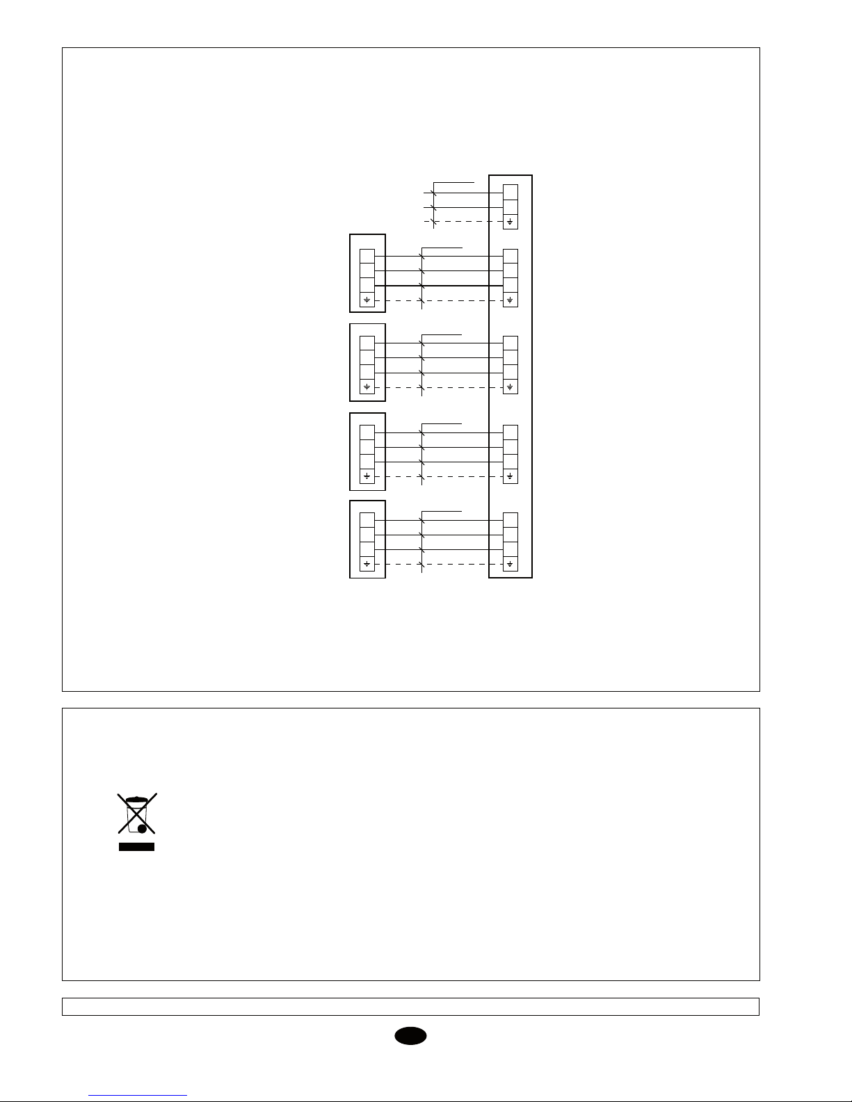
20
Schema di collegamento tra le unità
ERJC-28 DA
N
L
3
2
N(1)
3
2
N(1)
4 x 1,5 mm
2
3 x 4 mm
2
XT
XTA
3
2
N(1)
3
2
N(1)
4 x 1,5 mm
2
XT
XTB
230V, 1~50Hz
ERJC-28 DA
3
2
N(1)
3
2
N(1)
4 x 1,5 mm
2
XT
XTC
3
2
N(1)
3
2
N(1)
4 x 1,5 mm
2
XT
XTD
ATTENZIONE
Sul prodotto è presente questo simbolo. Ciò significa che al termine della sua vita utile non deve
essere mischiato con gli altri rifiuti domestici non classificati, ma deve essere eliminato come
previsto dalla normativa locale e nazionale vigente per la raccolta selettiva dei rifiuti e per la tutela
dell’ambiente.
La rottamazione del climatizzatore e il trattamento del refrigerante, dell’olio e degli altri componenti
devono essere effettuati da un installatore competente, a norma di legge.
Per maggiori informazioni, rivolgersi alle autorità competenti.
Dati e misure soggetti a variazioni senza preavviso.
I
ERKC-07 AA
ERKC-09 AA
ERKC-12 AA
ERKC-07 AA
ERKC-09 AA
ERKC-12 AA
ERKC-07 AA
ERKC-09 AA
ERKC-12 AA
ERKC-07 AA
ERKC-09 AA
ERKC-12 AA
ERKC-18 AA
ERKC-18 AA
ERKC-18 AA
ERKC-18 AA
21
Hinweise zum Einbau
Überprüfung
Bei Empfang der Ware muss diese sofort
auf mögliche Transportschäden hin über-
prüft werden. Eventuelle Beanstandungen
müssen dem Spediteur und der Versi-
cherungsgesellschaft schriftlich zur Anzeige
gebracht werden.
Umweltschutz
Die Verpackung muss gemäß den
örtlichen Auflagen in Sachen Um-
weltschutz entsorgt werden.
Enthält vom Kyoto-Protokoll erfasstes
fluoriertes Treibhausgas.
Art und Menge pro System sind dem jewei-
ligen Typenschild zu entnehmen.
GWP (Global Warming Potential): 2088.
Installation des Innengeräts
Montageplatte an der Wand befestigen.
Hierbei die Schrauben vorerst noch nicht
fest anziehen.
Montageplatte korrekt ausrichten und Schrau-
ben abschließend fest anziehen (Fig. 2).
Sollen die Leitungen über die Rückwand
des Geräts nach außen geführt werden,
muss in die W
and eine Öffnung mit einem
Durchmesser von 50 mm gebohrt werden.
Der Mauerdurchgang muss hierbei leicht
nach außen hin abfallen (Fig. 3 und 7).
Mauerdurchführung einsetzen.
Die Kältemittelleitungen können in verschie-
denen Positionen verlegt werden (Fig. 6).
Installation der Verbindungsleitungen
und des elektrischen Anschlusses über
die zentrale Montageplatte im rückwärti-
gen Teil des Gehäuses
Oberen Teil der Einheit auf der Montage-
platte einhängen und nach vorne drücken.
Innengerät auf Dauer an der Montageplatte
befestigen. Rohrleitung ohne Knickstellen
und sonstige Behinderungen vorsichtig
zurechtbiegen.
Rohrleitung und Kabel des Geräts durch
die Öffnung in der Wand führen und oberen
Teil des Innengeräts auf der Oberkante der
Montageplatte einhängen (Fig. 2).
Durch ein versuchsweises Hin- und Her-
schieben des Gehäuses
die korrekte An-
bringung des Geräts überprüfen.
in verschiedenen Positionen verlegt werden
kann.
In die Kondensatableitung ist ein (U-förmi-
ger) Siphon einzubauen (Fig. 4). Kunststoff-
Abflussrohr mit Innendurchmesser 12 mm
anschließen.
Das Abflussrohr muss mit dem Klebeband an
der Kälteleitung befestigt werden (Fig. 6).
Typisches Installationsbeispiel
(Fig. 1)
Die Skizze zeigt in schematischer Form
ein typisches Installationsbeispiel für diese
Geräte.
Nach Vornahme eines Abflusstests sind
alle Leitungen mit Hilfe des Klebebands 5
miteinander zu verbinden.
Vor Abschluss des Einbaus
Folgende Aspekte sind zu überprüfen:
- Die Spannung liegt stets zwi-
schen 198-254 V.
- Der Querschnitt der Speise-
kabel entspricht mindestens
dem in den entsprechenden
Schaltbildern empfohlenen
Richtwert.
- Das Kondenswasser fließt
unbehi
ndert ab und im Wasse-
rumlauf sind keine Leckstellen
zu beobachten.
- Die Benutzer sind entspre-
chend eingewiesen worden.
- Auf die Notwendigkeit einer
regelmäßigen Reinigung des
Luftfilters wurde hingewiesen.
- Das Garantiezertifikat wurde
ausgefüllt.
- Es wurden entsprechende Hin-
weise zur Wartung gegeben
bzw. eine regelmäßige War-
tung vertraglich vereinbart.
Hinweise zum Einbau
ERJC-24 DA / 28 DA
-
Kondensatableitung
Zur Ableitung des anfallenden Kondens-
wassers ist ein Schlauch vorgesehen, der
D
WANDLER
Werden bei der Kombination der Innen-
geräte ein oder mehrere Modelle mit
einem 3/8“-Gasventil installiert, muss der
mit dem Außengerät gelieferte Wandler
eingebaut werden. Jedes Außengerät
kommt mit drei Wandlern zur Auslieferung.
Page 21
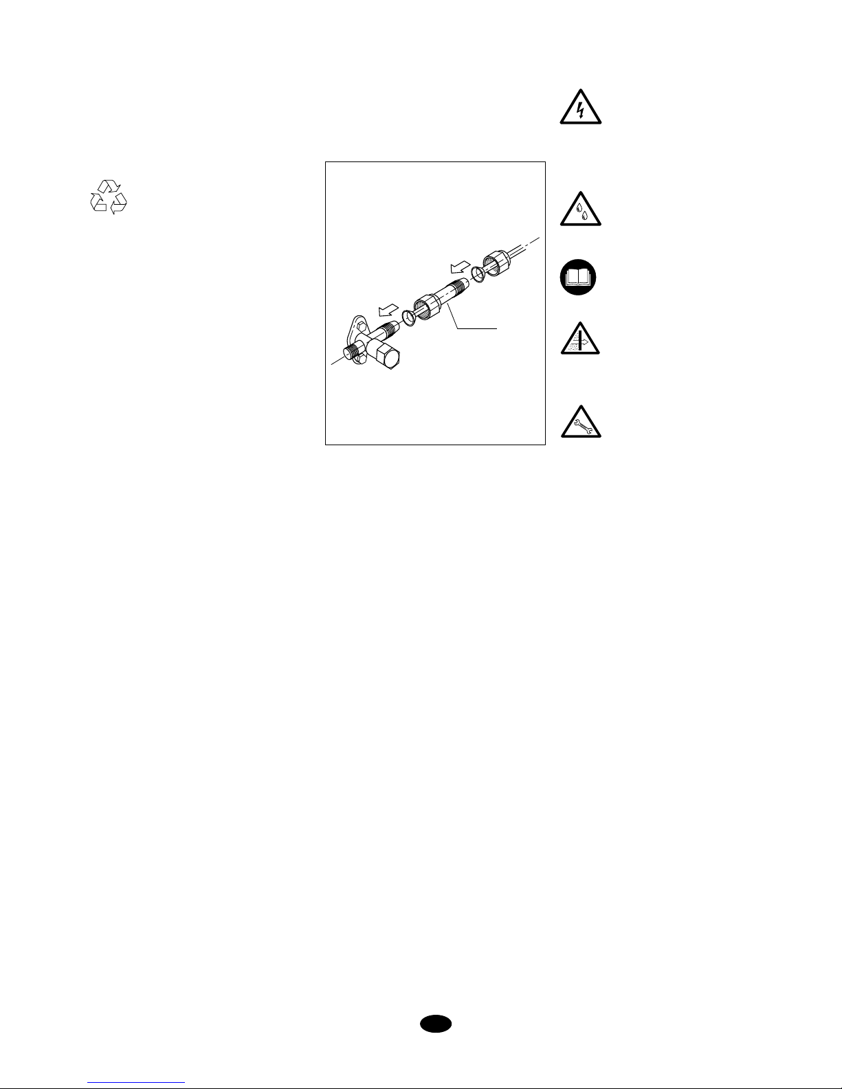
21
Hinweise zum Einbau
Überprüfung
Bei Empfang der Ware muss diese sofort
auf mögliche Transportschäden hin überprüft werden. Eventuelle Beanstandungen
müssen dem Spediteur und der Versicherungsgesellschaft schriftlich zur Anzeige
gebracht werden.
Umweltschutz
Die Verpackung muss gemäß den
örtlichen Auflagen in Sachen Umweltschutz entsorgt werden.
Enthält vom Kyoto-Protokoll erfasstes
fluoriertes Treibhausgas.
Art und Menge pro System sind dem jeweiligen Typenschild zu entnehmen.
GWP (Global Warming Potential): 2088.
Installation des Innengeräts
Montageplatte an der Wand befestigen.
Hierbei die Schrauben vorerst noch nicht
fest anziehen.
Montageplatte korrekt ausrichten und Schrauben abschließend fest anziehen (Fig. 2).
Sollen die Leitungen über die Rückwand
des Geräts nach außen geführt werden,
muss in die W
and eine Öffnung mit einem
Durchmesser von 50 mm gebohrt werden.
Der Mauerdurchgang muss hierbei leicht
nach außen hin abfallen (Fig. 3 und 7).
Mauerdurchführung einsetzen.
Die Kältemittelleitungen können in verschiedenen Positionen verlegt werden (Fig. 6).
Installation der Verbindungsleitungen
und des elektrischen Anschlusses über
die zentrale Montageplatte im rückwärtigen Teil des Gehäuses
Oberen Teil der Einheit auf der Montageplatte einhängen und nach vorne drücken.
Innengerät auf Dauer an der Montageplatte
befestigen. Rohrleitung ohne Knickstellen
und sonstige Behinderungen vorsichtig
zurechtbiegen.
Rohrleitung und Kabel des Geräts durch
die Öffnung in der Wand führen und oberen
Teil des Innengeräts auf der Oberkante der
Montageplatte einhängen (Fig. 2).
Durch ein versuchsweises Hin- und Herschieben des Gehäuses
die korrekte An-
bringung des Geräts überprüfen.
in verschiedenen Positionen verlegt werden
kann.
In die Kondensatableitung ist ein (U-förmiger) Siphon einzubauen (Fig. 4). KunststoffAbflussrohr mit Innendurchmesser 12 mm
anschließen.
Das Abflussrohr muss mit dem Klebeband an
der Kälteleitung befestigt werden (Fig. 6).
Typisches Installationsbeispiel
(Fig. 1)
Die Skizze zeigt in schematischer Form
ein typisches Installationsbeispiel für diese
Geräte.
Nach Vornahme eines Abflusstests sind
alle Leitungen mit Hilfe des Klebebands 5
miteinander zu verbinden.
Vor Abschluss des Einbaus
Folgende Aspekte sind zu überprüfen:
- Die Spannung liegt stets zwischen 198-254 V.
- Der Querschnitt der Speisekabel entspricht mindestens
dem in den entsprechenden
Schaltbildern empfohlenen
Richtwert.
- Das Kondenswasser fließt
unbehi
ndert ab und im Wasserumlauf sind keine Leckstellen
zu beobachten.
- Die Benutzer sind entsprechend eingewiesen worden.
- Auf die Notwendigkeit einer
regelmäßigen Reinigung des
Luftfilters wurde hingewiesen.
- Das Garantiezertifikat wurde
ausgefüllt.
- Es wurden entsprechende Hinweise zur Wartung gegeben
bzw. eine regelmäßige Wartung vertraglich vereinbart.
Hinweise zum Einbau
ERJC-24 DA / 28 DA
-
Kondensatableitung
Zur Ableitung des anfallenden Kondenswassers ist ein Schlauch vorgesehen, der
D
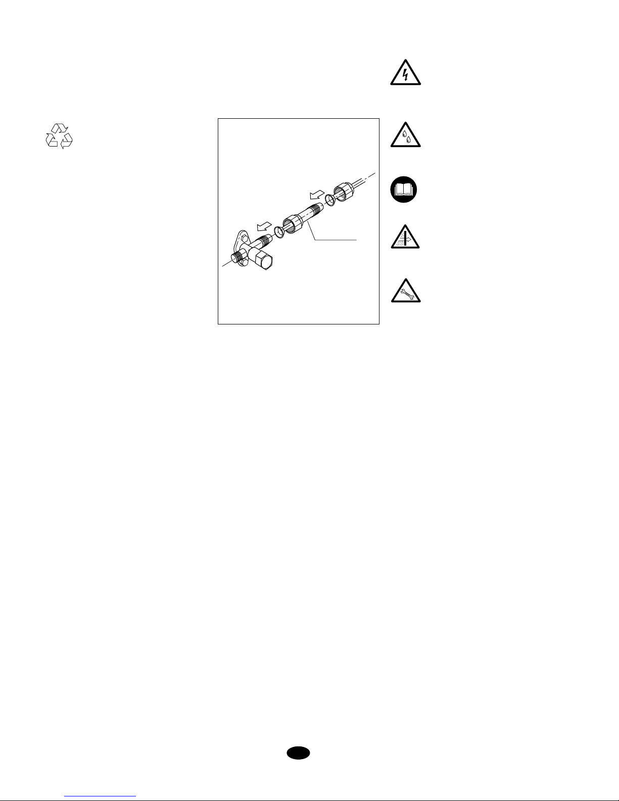
WANDLER
Werden bei der Kombination der Innengeräte ein oder mehrere Modelle mit
einem 3/8“-Gasventil installiert, muss der
mit dem Außengerät gelieferte Wandler
eingebaut werden. Jedes Außengerät
kommt mit drei Wandlern zur Auslieferung.
Page 22
22
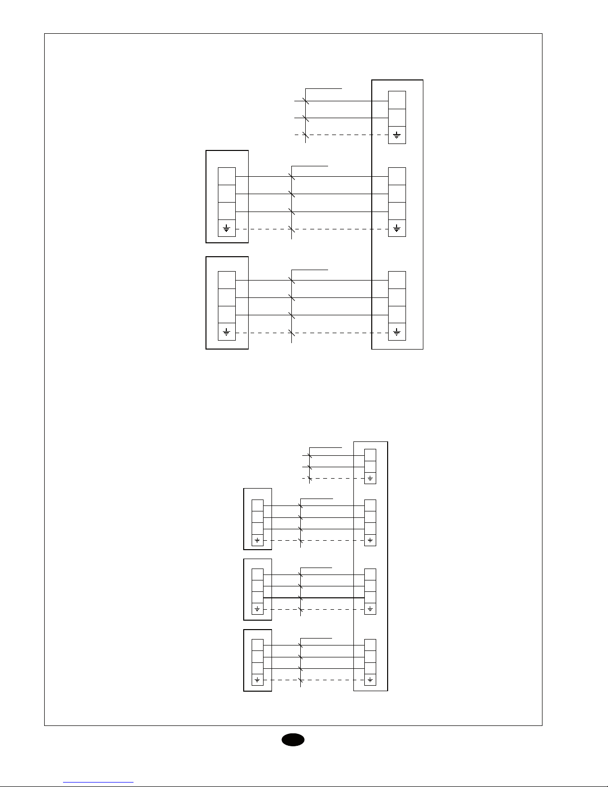
Verbindungsdiagramm
ERJC-22 DA
ERJC-24 DA
N
L
3
2
N(1)
3
2
N(1)
3
2
N(1)
3
2
N(1)
4 x 1,5 mm
2
4 x 1,5 mm
2
3 x 4 mm
2
XT
XT
XTB1
XTA1
230V, 1~50Hz
ERJC-22DA
N
L
3
2
N(1)
3
2
N(1)
4 x 1,5 mm
2
3 x 4 mm
2
XT
XTA
3
2
N(1)
3
2
N(1)
4 x 1,5 mm
2
XT
XTB
230V, 1~50Hz
ERJC-24 DA
3
2
N(1)
3
2
N(1)
4 x 1,5 mm
2
XT
XTC
D
ERKC-07 AA
ERKC-09 AA
ERKC-12 AA
ERKC-07 AA
ERKC-09 AA
ERKC-12 AA
ERKC-07 AA
ERKC-09 AA
ERKC-12 AA
ERKC-07 AA
ERKC-09 AA
ERKC-12 AA
ERKC-18 AA
ERKC-07 AA
ERKC-09 AA
ERKC-12 AA
ERKC-18 AA
ERKC-18 AA
ERKC-18 AA
ERKC-18 AA
Page 23
23
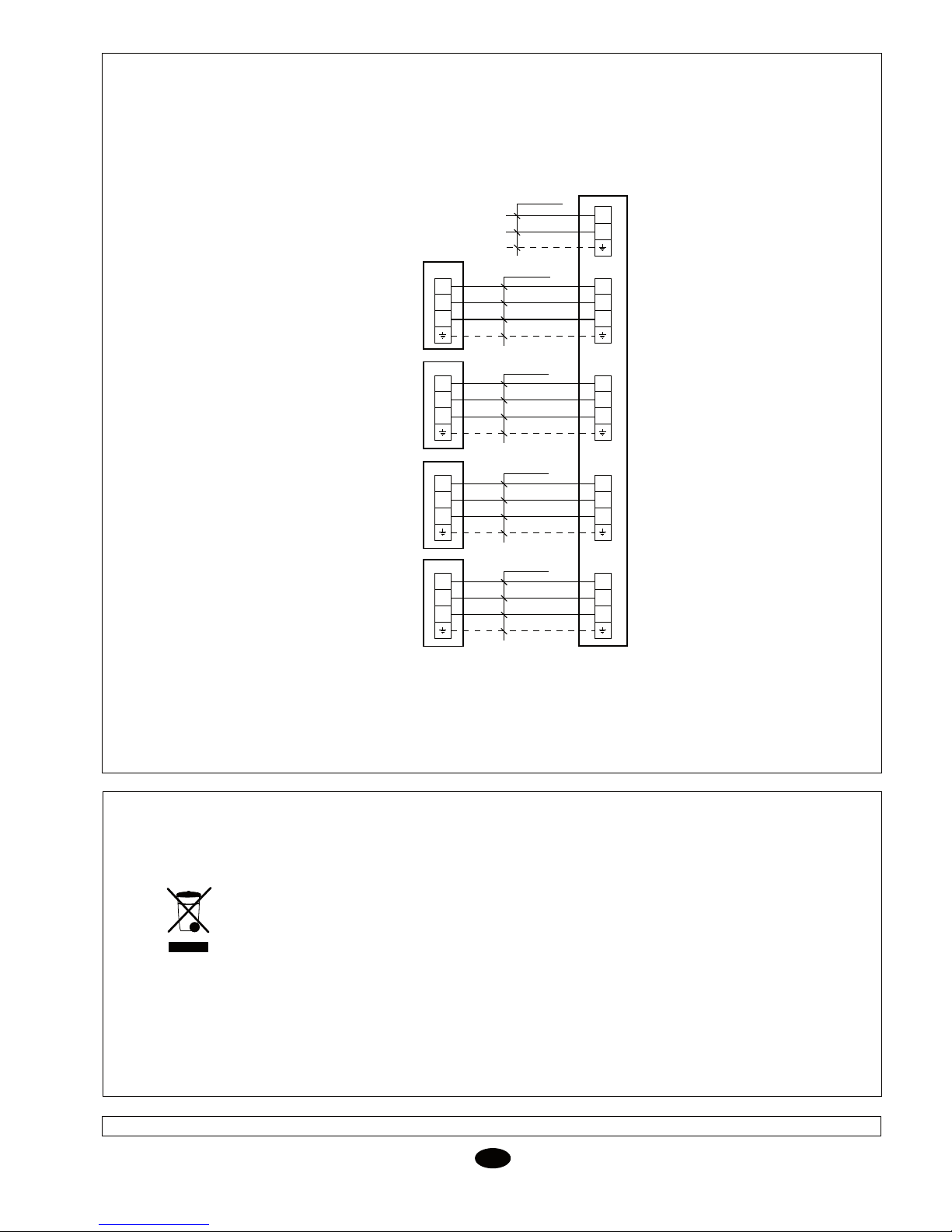
Verbindungsdiagramm
ERJC-28 DA
ZUR BEACHTUNG
Ihr Produkt ist mit dem nebenstehenden Symbol ausgezeichnet. Dies bedeutet, dass es nach Ablauf
der Betriebsdauer nicht mit dem normalen Hausmüll ausgesondert werden darf. Vielmehr hat die
Entsorgung des Geräts korrekt und umweltfreundlich in Übereinstimmung mit den diesbezüglich vor
Ort geltenden lokalen und nationalen Bestimmungen zu erfolgen.
Die Entsorgung des Klimageräts und die Weiterbehandlung des Kältemittels, des im Gerät verbleibenden Öls sowie aller sonstigen Bauteile muss von einem amtlich zugelassenen Installateur übernommen werden.
Weitere Informationen erteilen die zuständigen Behörden.
Technische Angaben und Maße können ohne vorherige Ankündigung geändert werden.
N
L
3
2
N(1)
3
2
N(1)
4 x 1,5 mm
2
3 x 4 mm
2
XT
XTA
3
2
N(1)
3
2
N(1)
4 x 1,5 mm
2
XT
XTB
230V, 1~50Hz
ERJC-28 DA
3
2
N(1)
3
2
N(1)
4 x 1,5 mm
2
XT
XTC
3
2
N(1)
3
2
N(1)
4 x 1,5 mm
2
XT
XTD
D
ERKC-07 AA
ERKC-09 AA
ERKC-12 AA
ERKC-07 AA
ERKC-09 AA
ERKC-12 AA
ERKC-07 AA
ERKC-09 AA
ERKC-12 AA
ERKC-07 AA
ERKC-09 AA
ERKC-12 AA
ERKC-18 AA
ERKC-18 AA
ERKC-18 AA
ERKC-18 AA
Page 24
24
SW
Installationsanvisningar
Kontroll av delarna
När du tar emot enheterna och de medföljande delarna måste du kontrollera dem för
att upptäcka eventuella transportskador.
Rapportera in eventuella fel till budfirman
och försäkringsbolaget.
Miljöskydd
Återvinn emballaget i enlighet med
lokala föreskrifter och EU:s riktlinjer
för att skydda miljön.
Innehåller fluorerad gas och omfattas av
Kyoto-protokollet (bidrar till växthuseffekten).
Se enhetens typskylt för information om vilken gastyp och mängden gas som används
i systemet.
GWP-faktor (Global Warming Potential):
2 088.
Installation av inomhusenheten
Sätt fast monteringsplattan på väggen. Dra
åt skruvarna lätt.
Rikta in monteringsplattan och dra sedan åt
skruvarna helt. (bild 2).
Om rören ska dras ut på enhetens baksida
borrar du ett hål med en diameter på 50
mm i väggen bakom plattan. Hå
let bör slutta
något nedåt, det vill säga, hålet utvändigt bör
hamna något under hålet invändigt (bild 3
och 7). Installera väggringen.
Kylrörledningarna kan installeras i olika
positioner (bild 6).
Installation av anslutningsrören och
elinstallation med mittenplattan placerad
på höljets baksida.
Häng fast enhetens överdel på monteringsplattan och tryck den mot väggen så att den
knäpper fast på plattan. Sätt fast inomhusenheten ordentligt på monteringsplattan. Böj
rören försiktigt så att de inte plattas till eller
täpps igen.
Dra ut enhetens rör och kablar genom hålet.
Häng fast inomhusdelens överdel på monteringsplattans överkant (se bild 2).
Försäkra dig om att enheten sitter på rätt
plats genom att först skjuta den åt vänster
och sedan åt höger.
Dräneringssystemet måste innehålla en
vinkel (U-form) (bild 4). Anslut en plastslang
för dränering
av kondens med en invändig
diameter på 12 mm.
Dräneringsslangen måste placeras tillsammans med kylrören och fästas med vinyltejp,
se bild 6.
Standardinstallation (bild 1)
Den här bilden ger en generell översikt över
en standardinstallation av den här typen av
anläggningar.
Efter att ha kontrollerat att det inte finns
några läckor sätter du samman alla rör
och kablar med hjälp av vinyltejpen, referensnr 3.
Innan du avslutar installationen
Kontrollera följande:
- Spänningen måste alltid vara på
mellan 198-254 V.
- Elkablarna måste minst ha den
area som rekommenderas.
- Att dräneringen av kondensvattnet fungerar som den ska
och att det inte finns läckor i
vätskesystemet.
- Att alla bruksanvisningar överlämnas till slutanvändaren.
- Att slutanvändaren har informerats om att luftfiltret måste rengöras med jämna mellanrum.
- Att garantikortet har fyllts i.
- Att slutanvändaren har fått
information om vilket underhåll
som måste göras eller att ett
underhållsavtal för regelbunden
skötsel upprättas.
Installationsanvisningar
ERJC-24 DA/28 DA
Dränering av kondens
Enhetens dräneringsslang är böjlig och kan
placeras i olika positioner.
OMVANDLARE
Om enhetskombinationen inkluderar en
eller flera modeller av typen med en
gasventil på 3/8 tum bör du installera den
omvandlare som medföljer utomhusenheten. Det medföljer tre omvandlare med
varje utomhusenhet.
Page 25
25
SW
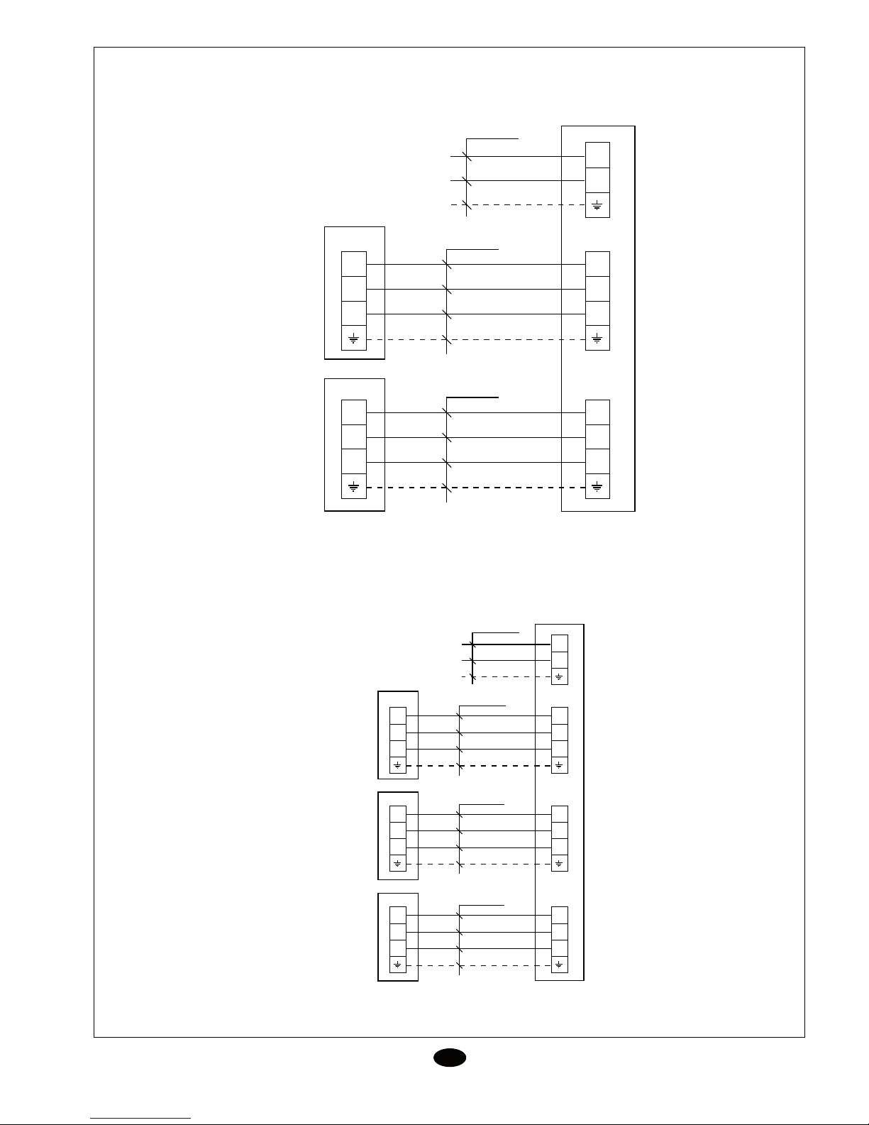
Diagram för sammankoppling
ERJC - 22 DA
ERJC - 24 DA
N
L
3
2
N(1)
3
2
N(1)
3
2
N(1)
3
2
N(1)
4 x 1,5 mm
2
4 x 1,5 mm
2
3 x 4 mm
2
XT
XT
XTB1
XTA1
230V, 1~50Hz
ERJC-22DA
N
L
3
2
N(1)
3
2
N(1)
4 x 1,5 mm
2
3 x 4 mm
2
XT
XTA
3
2
N(1)
3
2
N(1)
4 x 1,5 mm
2
XT
XTB
230V, 1~50Hz
ERJC-24 DA
3
2
N(1)
3
2
N(1)
4 x 1,5 mm
2
XT
XTC
ERKC-07 AA
ERKC-09 AA
ERKC-12 AA
ERKC-07 AA
ERKC-09 AA
ERKC-12 AA
ERKC-07 AA
ERKC-09 AA
ERKC-12 AA
ERKC-07 AA
ERKC-09 AA
ERKC-12 AA
ERKC-18 AA
ERKC-07 AA
ERKC-09 AA
ERKC-12 AA
ERKC-18 AA
ERKC-18 AA
ERKC-18 AA
ERKC-18 AA
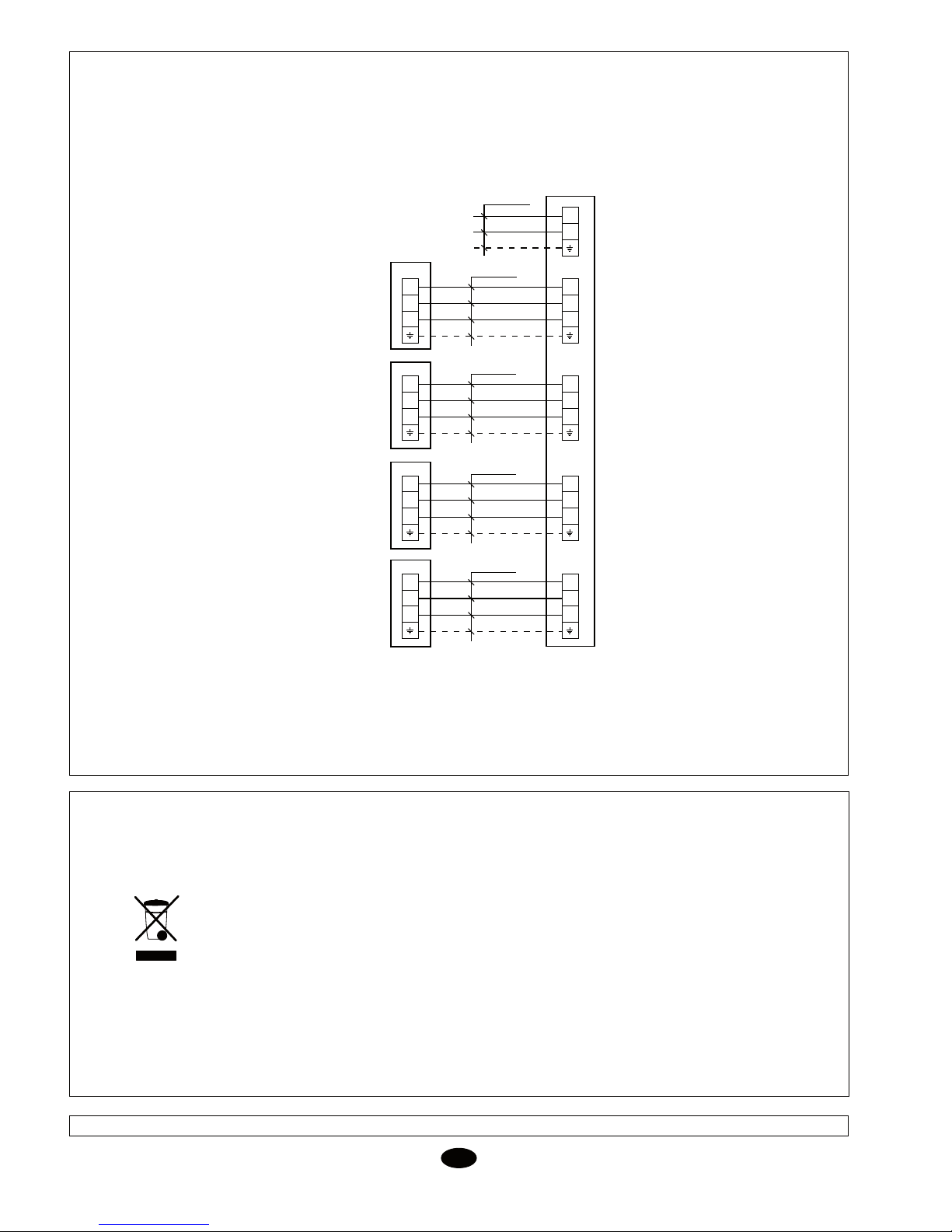
Page 26
26
SW
Diagram för sammankoppling
ERJC - 28 DA
N
L
3
2
N(1)
3
2
N(1)
4 x 1,5 mm
2
3 x 4 mm
2
XT
XTA
3
2
N(1)
3
2
N(1)
4 x 1,5 mm
2
XT
XTB
230V, 1~50Hz
ERJC-28 DA
3
2
N(1)
3
2
N(1)
4 x 1,5 mm
2
XT
XTC
3
2
N(1)
3
2
N(1)
4 x 1,5 mm
2
XT
XTD
VIKTIG INFORMATION!
Produkten är märkt med symbolen som visas till vänster. Detta innebär att produkten inte får
kasseras tillsammans med de vanliga hushållssoporna. Enheten måste kasseras och återvinnas i enlighet med lokala föreskrifter och EU:s riktlinjer för att värna om miljön. Nedmonteringen
av luftkonditioneringsutrustningen samt hanteringen av köldmediet, oljan och andra miljöfarliga
komponenter måste utföras av en auktoriserad installationstekniker i enlighet med tillämpliga
lagar. Kontakta de lokala myndigheterna på din ort för att få mer information om kassering och
återvinning.
Informationen i denna handbok, inklusive tekniska specifikationer, kan komma att ändras utan föregående meddelande.
ERKC-07 AA
ERKC-09 AA
ERKC-12 AA
ERKC-07 AA
ERKC-09 AA
ERKC-12 AA
ERKC-07 AA
ERKC-09 AA
ERKC-12 AA
ERKC-07 AA
ERKC-09 AA
ERKC-12 AA
ERKC-18 AA
ERKC-18 AA
ERKC-18 AA
ERKC-18 AA
ERKC-07, 09, 12, 18 AA
EN12100-1, EN12100-2, EN563, EN294, EN953, EN378, EN60335-1,
EN60335-2-40, EN61000-3, EN55014-1, EN55014-2, EN55104
98/37/CEE, 2006/95/CEE, 2004/108/CEE, 97/23/CEE
DECLARACION CE DE CONFORMIDAD SOBRE MAQUINAS
FIRMA:
FABRICANTE:
JOHNSON CONTROLS MANUFACTURING ESPAÑA, S.L.
Paseo Espronceda, 278, 08204 SABADELL
DIRECCIÓN:
Certificamos que el equipo descrito, ha sido diseñado, fabricado y probado de conformidad con los requisitos básicos de la Directiva de Equipos a
presión 97/23/CEE y sus correspondientes módulos de aplicación. Así mismo certificamos que el equipo es conforme a las exigencias básicas de las
Directivas Europeas que le son aplicables, incluidas las modificaciones de las mismas y las correspondientes transposiciones a la ley nacional.
TIPO:
DIRECTIVAS DE LA CE APLICADAS:
NORMAS ARMONIZADAS APLICADAS:
APLICACIÓN DE LA MÁQUINA: Aire Acondicionado/Refrigeración
CATEGORIA D.E.P. : I (50 < PSxV < 200)
Módulo de evaluación : A
EN ISO 9001, EN ISO 14001
NORMAS INTERNACIONALES Y
ESPECIFICACIONES TÉCNICAS APLICADAS:
LUGAR:
Sabadell, (España)
EN12100-1, EN12100-2, EN563, EN294, EN953, EN378, EN60335-1,
EN60335-2-40, EN61000-3, EN55014-1, EN55014-2, EN55104
98/37/EEC, 2006/95/EEC, 2004/108/EEC, 97/23/EEC
CE DECLARATION OF CONFORMITY
SIGNED BY:
MANUFACTURER:
JOHNSON CONTROLS MANUFACTURING ESPAÑA, S.L.
Paseo Espronceda, 278, 08204 SABADELL
ADDRESS:
We hereby certify that the mentioned equipment has been designed, manufactured and tested in accordance with essential requirements of Pressure
Equipment Directive 97/23/EEC and its relevant application modules. We futher certify that the equipment complies with the essential requirements
of the European Directives applicable, including their modifications and the corresponding transpositions from the national law.
TYPE:
EEC DIRECTIVES APPLIED:
APPLIED HARMONIZED STANDARDS:
MACHINE APPLICATION: Air Conditioning / Refrigeration
P.E.D. CATEGORY. : I (50 < PSxV < 200)
Assessment Module : A
EN ISO 9001, EN ISO 14001
APPLIED INTERNATIONAL TECHNICAL STANDARDS
AND SPECIFICATIONS:
PLACE:
Sabadell, (Spain)
ROMÁN LARRODA
QUALITY MANAGER
ROMÁN LARRODA
JEFE DE GESTIÓN DE CALIDAD
ERKC-07, 09, 12, 18 AA
Page 27
ERKC-07, 09, 12, 18 AA
EN12100-1, EN12100-2, EN563, EN294, EN953, EN378, EN60335-1,
EN60335-2-40, EN61000-3, EN55014-1, EN55014-2, EN55104
98/37/CEE, 2006/95/CEE, 2004/108/CEE, 97/23/CEE
DECLARACION CE DE CONFORMIDAD SOBRE MAQUINAS
FIRMA:
FABRICANTE:
JOHNSON CONTROLS MANUFACTURING ESPAÑA, S.L.
Paseo Espronceda, 278, 08204 SABADELL
DIRECCIÓN:
Certificamos que el equipo descrito, ha sido diseñado, fabricado y probado de conformidad con los requisitos básicos de la Directiva de Equipos a
presión 97/23/CEE y sus correspondientes módulos de aplicación. Así mismo certificamos que el equipo es conforme a las exigencias básicas de las
Directivas Europeas que le son aplicables, incluidas las modificaciones de las mismas y las correspondientes transposiciones a la ley nacional.
TIPO:
DIRECTIVAS DE LA CE APLICADAS:
NORMAS ARMONIZADAS APLICADAS:
APLICACIÓN DE LA MÁQUINA: Aire Acondicionado/Refrigeración
CATEGORIA D.E.P. : I (50 < PSxV < 200)
Módulo de evaluación : A
EN ISO 9001, EN ISO 14001
NORMAS INTERNACIONALES Y
ESPECIFICACIONES TÉCNICAS APLICADAS:
LUGAR:
Sabadell, (España)
EN12100-1, EN12100-2, EN563, EN294, EN953, EN378, EN60335-1,
EN60335-2-40, EN61000-3, EN55014-1, EN55014-2, EN55104
98/37/EEC, 2006/95/EEC, 2004/108/EEC, 97/23/EEC
CE DECLARATION OF CONFORMITY
SIGNED BY:
MANUFACTURER:
JOHNSON CONTROLS MANUFACTURING ESPAÑA, S.L.
Paseo Espronceda, 278, 08204 SABADELL
ADDRESS:
We hereby certify that the mentioned equipment has been designed, manufactured and tested in accordance with essential requirements of Pressure
Equipment Directive 97/23/EEC and its relevant application modules. We futher certify that the equipment complies with the essential requirements
of the European Directives applicable, including their modifications and the corresponding transpositions from the national law.
TYPE:
EEC DIRECTIVES APPLIED:
APPLIED HARMONIZED STANDARDS:
MACHINE APPLICATION: Air Conditioning / Refrigeration
P.E.D. CATEGORY. : I (50 < PSxV < 200)
Assessment Module : A
EN ISO 9001, EN ISO 14001
APPLIED INTERNATIONAL TECHNICAL STANDARDS
AND SPECIFICATIONS:
PLACE:
Sabadell, (Spain)
ROMÁN LARRODA
QUALITY MANAGER
ROMÁN LARRODA
JEFE DE GESTIÓN DE CALIDAD
ERKC-07, 09, 12, 18 AA
Page 28

www.johnsoncontrols.com
 Loading...