

Page 1
271846-YTG-B-0208
SINGLE PACKAGE AIR
CONDITIONING
WATER COOLED
®
MODELS: CU060 - 300 5-25 TONS
VERTICAL
MODELS: CH060 - 5-10 TONS
HORIZONTAL
FOR DISTRIBUTION USE ONLY - NOT TO BE USED AT POINT OF RETAIL SALE
Page 2

TABLE OF CONTENTS
271846-YTG-B-0208
DESCRIPTION. . . . . . . . . . . . . . . . . . . . . . . . . . . . . . 3
APPLICATION FLEXIBILITY. . . . . . . . . . . . . . . . . . . 3
CABINET . . . . . . . . . . . . . . . . . . . . . . . . . . . . . . . . . . 3
REFRIGERATION CIRCUITS . . . . . . . . . . . . . . . . . . 3
INDOOR FANS . . . . . . . . . . . . . . . . . . . . . . . . . . . . . 3
ELECTRICAL/CONTROLS . . . . . . . . . . . . . . . . . . . . 3
FILTERS. . . . . . . . . . . . . . . . . . . . . . . . . . . . . . . . . . . 3
FACTORY INSTALLED. . . . . . . . . . . . . . . . . . . . . . . 4
FIELD INSTALLED . . . . . . . . . . . . . . . . . . . . . . . . . . 4
SUPPLY AIR/RETURN AIR CONFIGURATION . . . 23
LIST OF FIGURES
Fig.# Pg.#
1 DIMENSIONAL DATA - CH 5 TON HORIZONTAL
MODEL . . . . . . . . . . . . . . . . . . . . . . . . . . . . . . . . . . . .16
2 DIMENSIONAL DATA - CH 8 & 10 TON
HORIZONTAL MODELS . . . . . . . . . . . . . . . . . . . . . . .17
3 PHYSICAL CONFIGURATION DATA - CH 8 &
10 TON WATER SIDE ECONOMIZER . . . . . . . . . . . .18
4 DIMENSIONAL DATA - CU 5, 8, AND 10 TON
VERTICAL MODELS. . . . . . . . . . . . . . . . . . . . . . . . . .19
5 DIMENSIONAL DATA - CU 15 TON VERTICAL
MODEL . . . . . . . . . . . . . . . . . . . . . . . . . . . . . . . . . . . .20
6 DIMENSIONAL DATA - CU 20 TON VERTICAL
MODEL . . . . . . . . . . . . . . . . . . . . . . . . . . . . . . . . . . . .21
7 DIMENSIONAL DATA - CU 25 TON VERTICAL
MODEL . . . . . . . . . . . . . . . . . . . . . . . . . . . . . . . . . . . .22
8 SUPPLY AIR/RETURN AIR CONFIGURATION . . . . .23
9 HOT WATER & STEAM HEATING COILS
DIMENSIONAL DATA . . . . . . . . . . . . . . . . . . . . . . . . .24
10 HOT WATER & STEAM HEATING COILS
PERFORMANCE DATA . . . . . . . . . . . . . . . . . . . . . . .25
11 TYPICAL WATER-SIDE ECONOMIZER PHYSICAL
CONFIGURATION. . . . . . . . . . . . . . . . . . . . . . . . . . . .26
12 TYPICAL WATER-SIDE ECONOMIZER PIPING
SCHEMATIC . . . . . . . . . . . . . . . . . . . . . . . . . . . . . . . .27
13 TYPICAL WATER-SIDE ECONOMIZER CONTROL -
15-20 TON VERTICAL (208-230 V/3PH/60HZ). . . . . .28
LIST OF TABLES
Tbl.# Pg.#
1 GENERAL DATA - CH060-120 5-10 TON
HORIZONTAL MODELS. . . . . . . . . . . . . . . . . . . . . . . . 5
2 GENERAL DATA CU 5-25 TON VERTICAL
MODELS. . . . . . . . . . . . . . . . . . . . . . . . . . . . . . . . . . . . 6
3 SUPPLY AIR BLOWER PERFORMANCE
CH060-120, 5 TO 10 TON HORIZONTAL MODELS . . 7
4 SUPPLY AIR BLOWER PERFORMANCE
CU060-240, 5 TO 20 TON VERTICAL MODELS . . . . . 8
5 SUPPLY AIR BLOWER PERFORMANCE
CU300, 25 TON VERTICAL MODEL . . . . . . . . . . . . . . 8
6 WATERSIDE PRESSURE DROP - CU MODELS . . . . 9
7 WATER PRESSURE DROP DATA - CH MODELS . . 10
8 COOLING PERFORMANCE DATA - CH 5-10 TON
HORIZONTAL MODELS. . . . . . . . . . . . . . . . . . . . . . . 11
9 COOLING PERFORMANCE DATA - CU 5-20 TON
VERTICAL MODELS. . . . . . . . . . . . . . . . . . . . . . . . . . 12
10 COOLING PERFORMANCE DATA - CU 25 TON
VERTICAL MODELS. . . . . . . . . . . . . . . . . . . . . . . . . . 13
11 WATER-SIDE ECONOMIZER COOLING
PERFORMANCE DATA - CH 5-10 TON MODELS . . 13
12 WATER-SIDE ECONOMIZER COOLING
PERFORMANCE DATA - CU 5-25 TON
VERTICAL MODELS. . . . . . . . . . . . . . . . . . . . . . . . . . 14
13 STANDARD MOTORS CU 5-25 TON MODELS. . . . . 14
14 OVERSIZED MOTORS CU 5-25 TON MODELS . . . . 15
15 STANDARD MOTORS CH 5-10 TON MODELS. . . . . 15
16 OVERSIZED MOTORS CH 8-10 TON MODELS . . . . 15
17 DIMENSIONAL DATA - CU 5, 8, AND 10 TON
VERTICAL MODELS. . . . . . . . . . . . . . . . . . . . . . . . . . 19
2 Johnson Controls Unitary Products
Page 3

271846-YTG-B-0208
DESCRIPTION
These units are completely assembled, piped, wired, charged
and tested at the factory and are shipped ready for immediate
installation. Only the power supply wiring, the thermostat wir
ing, the condenser water piping, the condensate drain piping
and the ductwork are required to complete the installation.
Units include a one-year limited warranty on all replacement
parts and a five-year limited warranty on each compressor.
APPLICATION FLEXIBILITY
These “cooling only” units can be applied with:
1. Cooling towers.
2. Well or surface water providing the temperature and the GPM of the water meet the application limitations of the unit.
3. Brackish or salt water and a secondary heat exchanger.
They can be installed:
1. Within the conditioned space as “free standing” units without any ductwork. Supply air plenum and return air grille accessories are available for these freestanding applications.
2. In an equipment room with both supply and return air ductwork
GENERAL
Horizontal (CH) units are designed for suspended mounting.
HWC models are shipped with ‘straight-through’ evaporator
fan discharge as standard. Airflow orientation is field convertible to side discharge. Vertical (CU) units are designed for
free-standing floor mounting. All units are completely factory
wired and pre-piped. Water supply, water outlet, and condensate drain connections are via female pipe thread fittings.
All models 5 -25 tons ship as factory-charged unitized packages. The 5 -15 ton units may be field split between the evaporator /compressor section and the upper blower section;
installation is possible through standard height doorways and
elevators. All packages are designed for free-standing floor
mounting. All models are shipped with vertical evaporator fan
discharge as standard. Units are completely factory wired
and piped. Dual circuit models feature internally manifolded
condensers.
CABINET
charge are provided with the unit, for field installation. Duct
flange on CU240 & CU300 evaporator return is incorporated
into the filter frame.
REFRIGERATION CIRCUITS
-
All models utilize "Scroll" type hermetic compressors. Compressors are mounted on rubber isolators to minimize vibration transmission. Internal overload protection is provided.
External high pressure and low pressure cutout switches are
included in each compressor control circuit. The 5 ton units
have a single refrigeration circuit. The 8 -20 ton units feature
two independent refrigeration circuits. The 25 ton unit has
three independant refrigeration circuits. Each refrigeration cir
cuit includes an adjustable thermal expansion valve (with
external equalizer), liquid line filter drier, sight glass/moisture
indicator, and service gauge ports.
The evaporator coils are constructed of internally enhanced
copper tubes mechanically bonded to rippled aluminum plate
fins. The evaporator coil is employed in a draw-through configuration, and features inter-laced circuiting. Large evaporator coil face area minimizes potential water blow-off.
The high-efficiency tube-in-tube condensers feature a convoluted inner tube design for optimum performance. Standard
models feature a copper inner tube surrounded by a steel
outer tube, and carry a 400 psig working pressure rating.
INDOOR FANS
Forward curved, double inlet and double width centrifugal
blowers are used for evaporator air movement. Large diameter wheels are employed to provide required airflow performance at minimum rpm and noise levels. Blower wheels are
fabricated of galvanized steel. Blowers employ solid steel
shafts, supported in permanently lubricated ball bearings. All
blowers are belt driven. Variable-pitch motor sheaves allow
for field adjustment of blower rpm.
ELECTRICAL/CONTROLS
All units are completely factory wired with all necessary controls. Manual reset protection is provided on evaporator
blower motors. A manual reset circuit is also provided on
each compressor control circuit in the event of high/low pressure cutout. A 24 volt control circuit, with oversize transformer, is provided for field connection. Units are designed to
operate with conventional thermostat control interface.
-
All cabinets are completely constructed of 18 Ga. corrosion
resistant "Galvalume" coated steel. The entire unit interior
(both evaporator and condensing section) is insulated with
1/2" thick, 2 lbs. density insulation. Service panels are
equipped with lifting handles for ease of removal and han
dling. Duct flanges for return air intake and evaporator dis-
Johnson Controls Unitary Products
-
FILTERS
All models are shipped with 2 inch thick medium-efficiency
throwaway filters factory installed. Filters are accessible from
either front or right side on 5-15 ton models. The CU240 and
CU300 filter rack is external to the cabinet (shipped loose).
3
Page 4

271846-YTG-B-0208
FACTORY INSTALLED
OVERSIZED EVAPORATOR FAN MOTORS
Increased horsepower motors and drive components are
available for those applications where external static pressure requirements exceed the capability of the standard
motor.
CORROSION RESISTANT COATINGS
Evaporator coil shall receive a 1-mil thickness of a cathodic
epoxy type electro-deposition coating, applied in a multiple
dip and bake process.
STAINLESS STEEL DRAIN PAN
Evaporator coil (and optional Water Side Economizer coil)
drain pan shall be fabricated 304 stainless steel material The
3/4 in NPT drain connection fitting is also of 304 stainless
steel.
HOT GAS BYPASS
Adjustable hot gas regulator and all necessary piping shall be
installed on lead compressor circuit. Bypass capacity shall be
minimum 50% of compressor capacity. The bypass valve
opens at a preset suction pressure to prevent coil freeze-up
at light evaporator load, or low airflow conditions. The use of
factory installed Condenser Pressure Control option is
strongly recommended when Hot Gas Bypass is installed.
ANTI-SHORT CYCLE TIMER
Time delay relay will be provided for each compressor circuit.
Compressor will be lock out for 5 minutes when thermostat
contacts open, or there is a momentary power outage.
FIELD INSTALLED
WATER SIDE ECONOMIZER
Commercial Water Cooled Air Conditioners can achieve substantial operating cost reductions by utilizing the cooling
effect made available by low temperature water. The Waterside Economizer Kit consists of a field installed water cooling
coil, pre-assembled external piping sections, a three-way
motorized valve, and all necessary controls for unit operation
from a conventional 24-Volt thermostat.
HOT WATER & STEAM COILS
Hydronic heating coils shall mount on return air side of cooling coil.
RETURN AIR GRILL
Available on 5-15 ton CU models only. Recommended for
applications where return air is not ducted and air is drawn
directly from the conditioned space.
DISCHARGE PLENUM
Plenums mount on top of the evaporator section, with fans
arranged for vertical discharge. Double deflection grills shall
allow air discharge in multiple directions.
OVERSIZED EVAPORATOR FAN MOTORS
Increased horsepower motors and drive components are
available as a kit. Units are field upgradeable for applications
where external staic pressure requirements exceed the capa
bility of the standard motor.
CONDENSER PRESSURE CONTROL
Water regulating valves provide control of the quantity of condenser water supplied to the unit by sensing the condensing
temperature. The field installed Condenser Control Option
provides a regulating valve for each internal condenser water
circuit. Standard Water Regulating Valve carries a 150 psig
working pressure rating. The valve is installed inside of the
unit cabinet.
-
4 Johnson Controls Unitary Products
Page 5

271846-YTG-B-0208
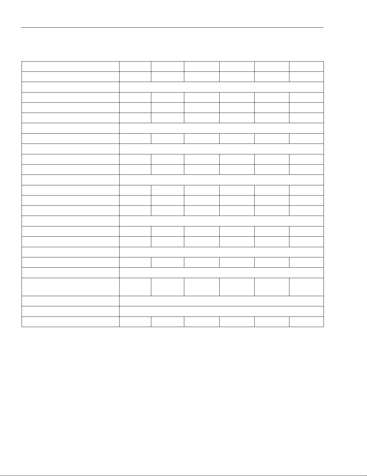
TABLE 1: GENERAL DATA - CH060-120 5-10 TON HORIZONTAL MODELS
Model - CH CH060 CH096 CH120
Nominal Cooling(Ton) 5 8 10
Cooling Performance
Gross Cooling Capacity(Btuh) 64100 101800 126000
Design CFM 2000 3200 4000
EER 13.3 13.4 12.0
Compressor-Type Scroll
Number Used 1 2 2
Evaporator Coil-Type Copper Tubes, Aluminum Fins
Face Area(sq ft) 5.28 9.17 9.17
Rows/FPI 3/13 3/13 3/13
Condenser-Type Coaxial
Number Used/Tons Capacity 1/5 2/4 2/5
Nominal Water flow rate (gpm) 15 24 30
Condenser Water Connections 1" FPT 1-1/4" FPT 1-1/4" FPT
Evaporator Fan-Type Centrifugal, Forward Curved
Number Used 1 2 2
Diameter x Width (in) 10x10 10x8 10x8
Drive Adjustable Belt
Motor HP (Standard/Oversize) 1/NA 1.5/2 2/3
Filters
Number Used-Size(in) 2-20x20x2 2-20x25x2
1-20x20x2
2-20x25x2
1-20x20x2
Condensate Drain Connection 3/4FPT
Weight 460 710 760
NOTE: Cooling performance is rated at 80°F dry bulb 67°F wet bulb entering air temperature, CFM listed, 85°F entering
95°F leaving water temperature, and water flow rate listed. Gross capacity does not include the effect of evaporator fan motor heat.
Johnson Controls Unitary Products
5
Page 6
271846-YTG-B-0208
TABLE 2: GENERAL DATA CU 5-25 TON VERTICAL MODELS
Model - CU CU060A CU096A CU120A CU180A CU240A CU300
Nominal Cooling(Ton) 5 8 10 15 20 25
Cooling Performance
Gross Cooling Capacity(Btuh) 63300 100600 127800 188600 246800 322000
Design CFM 2000 3200 4000 6000 8000 10000
EER 12.5 13.2 12.5 12.0 11.6 11.5
Compressor-Type Scroll
Number Used 1 2 2 2 2 3
Evaporator Coil-Type Copper Tubes, Aluminum Fins
Face Area(sq ft) 5.00 9.37 10.50 15.11 19.00 19.79
Rows/FPI 3/12 3/12 3/13 3/12 3/14 4/12
Condenser-Type Coaxial
Number Used/Tons Capacity 1/5 2/4 2/5 2/7.5 2/10 3/7.5
Nominal Water flow rate (gpm) 15 24 30 45 60 78
Unit Water Connection Size 1" FPT 1-1/4" FPT 1-1/4" FPT 1-1/2" FPT 2" FPT 2" FPT
Evaporator Fan-Type Centrifugal, Forward Curved
Number Used 1 1 1 2 2 2
Diameter x Width (in) 12x9 15x12 15x12 15x9 15x11 15x11
Drive Adjustable Belt
Motor HP (Standard/Oversize) 1/1.5 1.5/2 2/3 3/5 5/7.5 7.5/10
Filters
Number Used-Size(in) 2-20x16x2 4-14x25x2 6-14x20x2 2-16x20x2
6-20x25x2 8-20x20x2
4-16x25x2
Condensate Drain Connection 3/4FPT
Weight
Shipping 625 815 975 1350 1525 1825
NOTE: Cooling performance is rated at 80°F dry bulb 67°F wet bulb entering air temperature, CFM listed, 85°F entering
95°F leaving water temperature, and water flow rate listed. Gross capacity does not include the effect of evaporator fan motor heat.
6 Johnson Controls Unitary Products
Page 7
271846-YTG-B-0208
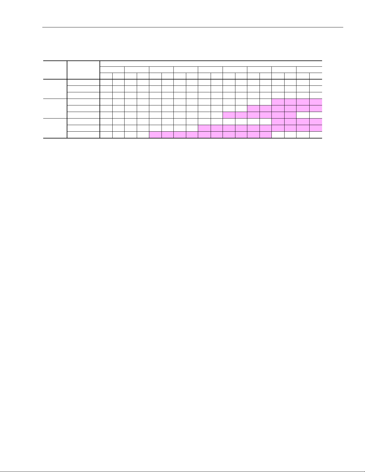
TABLE 3: SUPPLY AIR BLOWER PERFORMANCE CH060-120, 5 TO 10 TON HORIZONTAL MODELS
EXTERNAL STATIC PRESSURE - Inches W.C.
MODEL # SUPPLY CFM
1800
CH060
CH096
CH120
NOTE:
1. At higher evaporator airflows, and wet bulb conditions condensate carry-over may occur. Adjust airflow downward as necessary.
2. Values include pressure drop from wet coil and clean filters.
3. Shaded areas indicate oversize motors.
2000
2200
3000
3200
3400
3600
4000
4400
0.2 0.4 0.6 0.8 1.0 1.2 1.4 1.6
RPM BHP RPM BHP RPM BHP RPM BHP RPM BHP RPM BHP RPM BHP RPM BHP
846 0.41 936 0.48 1024 0.56 1107 0.64 1195 0.74 1259 0.82 1325 0.90 1400 0.99 - 917 0.54 999 0.62 1079 0.71 1157 0.79 1233 0.89 1305 0.98 - - - - - 994 0.70 1069 0.79 1142 0.88 1214 0.98 - - - - - - - - - 810 0.65 900 0.78 986 0.91 1066 1.04 1143 1.17 1221 1.32 1294 1.48 1363 1.63 1433 1.79
851 0.78 938 0.91 1018 1.04 1095 1.18 1170 1.32 1236 1.42 1305 1.56 1380 1.74 1447 1.90
892 0.91 974 1.05 1051 1.19 1125 1.33 1196 1.48 1266 1.64 1320 1.81 1390 1.90 - -
927 1.05 1006 1.20 1081 1.34 1152 1.50 1220 1.65 1287 1.81 1353 1.98 1405 2.07 1472 2.17
1012 1.40 1085 1.56 1153 1.73 1220 1.89 1283 2.06 1345 2.23 1405 2.41 1464 2.59 1522 2.78
1100 1.83 1166 2.00 1230 2.18 1292 2.37 1351 2.55 1410 2.74 1466 2.92 - - - -
1.8
RPM BHP
Johnson Controls Unitary Products
7
Page 8
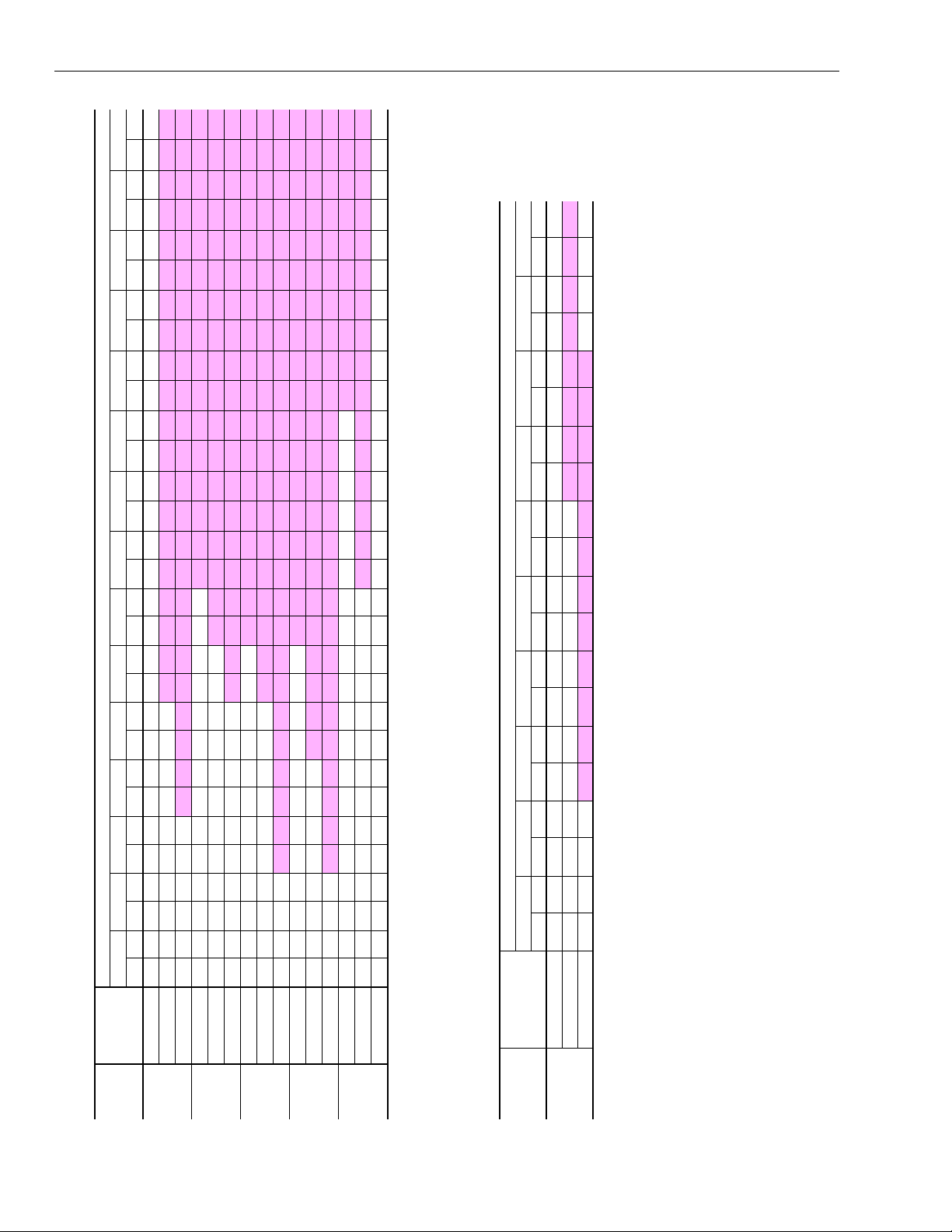
1.8 2.0 2.2 2.4 2.6 2.8 3.0
271846-YTG-B-0208
RPM BHP RPM BHP RPM BHP RPM BHP RPM BHP RPM BHP RPM BHP
EXTERNAL STATIC PRESSURE - Inches W.C.
EXTERNAL STATIC PRESSURE - Inches - W.C.
0.2 0.4 0.6 0.8 1.0 1.2 1.4 1.6 1.8 2.0
RPM BHP RPM BHP RPM BHP RPM BHP RPM BHP RPM BHP RPM BHP RPM BHP RPM BHP RPM BHP
0.2 0.4 0.6 0.8 1.0 1.2 1.4 1.6
791 0.46 872 0.53 948 0.60 1019 0.68 1090 0.76 1159 0.85 1193 0.89 1259 0.98 1321 1.07 1380 1.16 1437 1.25 1492 1.35 1544 1.44 - - - -
860 0.60 935 0.69 1006 0.77 1077 0.85 1136 0.94 1199 1.03 1263 1.12 1324 1.22 1383 1.32 1440 1.42 1494 1.52 - - - - - -
931 0.79 1001 0.88 1067 0.97 1129 1.06 1189 1.15 1247 1.25 1305 1.35 1363 1.45 1419 1.55 - - - - - - - - - -
568 0.70 628 0.81 688 0.92 746 1.05 801 1.19 855 1.35 906 1.50 954 1.65 1001 1.81 1046 1.97 - - - - - - - -
594 0.82 651 0.94 707 1.06 762 1.19 816 1.33 867 1.49 917 1.65 964 1.81 1010 1.98 - - - - - - - - - -
625 0.97 679 1.10 731 1.22 784 1.35 835 1.50 884 1.66 933 1.83 979 2.00 - - - - - - - - - - - -
620 1.04 666 1.16 716 1.29 765 1.43 815 1.56 864 1.71 912 1.88 958 2.00 1003 2.03 1046 2.41 1088 2.60 1129 2.78 1169 2.97 - - - -
681 1.40 721 1.53 765 1.68 811 1.83 856 1.97 900 2.13 945 2.29 988 2.46 1030 2.65 1071 2.84 1112 3.05 - - - - - - - -
726 1.77 760 1.91 797 2.05 837 2.21 878 2.38 919 2.54 960 2.70 1001 2.87 1040 3.05 - - - - - - - - - -
645 1.52 709 1.79 770 2.06 829 2.35 885 2.65 939 2.96 991 3.28 1042 3.61 1092 3.96 1140 4.32 1190 4.71 - - - - - - - -
700 2.00 759 2.30 815 2.60 870 2.91 922 3.23 973 3.56 1022 3.90 1070 4.25 1116 4.62 1162 4.99 - - - - - - - - - -
761 2.63 815 2.94 867 3.26 917 3.60 966 3.94 1014 4.29 1060 4.66 1104 5.02 - - - - - - - - - - - - - -
659 2.10 714 2.37 767 2.65 817 2.94 866 3.23 912 3.52 957 3.82 998 4.13 1037 4.44 1076 4.76 1115 5.11 1154 5.47 1193 5.73 1230 6.10 1265 6.46
719 2.81 770 3.11 818 3.42 865 3.73 910 4.05 954 4.37 997 4.70 1038 5.03 1078 5.36 1115 5.71 1151 6.08 1186 6.46 1220 6.84 1254 7.23 - -
7200
8000
CU240
782 3.67 828 4.00 873 4.34 916 4.68 959 5.02 1000 5.37 1040 5.73 1079 6.09 1117 6.45 1154 6.81 1190 7.18 - - - - - - - -
8800
9000 800 3.93 846 4.27 890 4.61 932 4.96 974 5.32 1014 5.67 1053 6.03 1092 6.40 1129 6.77 1166 7.14
11000 958 6.95 996 7.37 1033 7.79 1069 8.21 1104 8.63 1139 9.05 1173 9.48 1206 9.92 - - - -
10000 878 5.29 920 5.67 960 6.05 999 6.43 1037 6.82 1074 7.21 1111 7.61 1147 8.01 1182 8.41 1216 8.82
CU300
NOTE:
At higher evaporator airflows and wet bulb conditions, condensate carry-over may occur. Adjust airflow downward as necessary
Values include pressure drop from wet coil and clean filters.
Shaded areas indicate oversize motors.
MODEL # SUPPLY CFM
TABLE 5: SUPPLY AIR BLOWER PERFORMANCE CU300, 25 TON VERTICAL MODEL
NOTE:
At higher evaporator airflows and wet bulb conditions, condensate carry-over may occur. Adjust airflow downward as necessary
Values include pressure drop from wet coil and clean filters.
Shaded areas indicate oversize motors.
RPM BHP RPM BHP RPM BHP RPM BHP RPM BHP RPM BHP RPM BHP RPM BHP
1800
2000
2200
3000
3200
3400
3600
4000
4400
5400
6000
6600
TABLE 4: SUPPLY AIR BLOWER PERFORMANCE CU060-240, 5 TO 20 TON VERTICAL MODELS
MODEL # SUPPLY CFM
CU060
CU096
CU120
CU180
8 Johnson Controls Unitary Products
Page 9
271846-YTG-B-0208
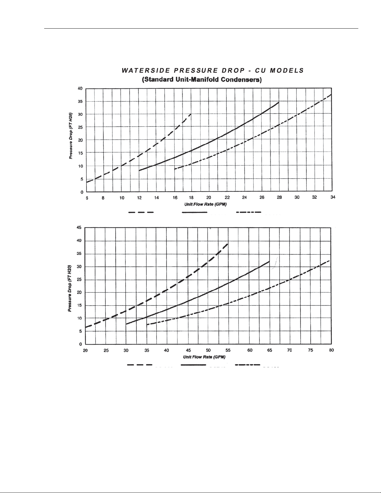
TABLE 6: WATERSIDE PRESSURE DROP - CU MODELS
CU060 CU096 CU120
CU180 CU240 CU300
Johnson Controls Unitary Products
9
Page 10

TABLE 7: WATER PRESSURE DROP DATA - CH MODELS
271846-YTG-B-0208
10 Johnson Controls Unitary Products
Page 11

271846-YTG-B-0208
TABLE 8: COOLING PERFORMANCE DATA - CH 5-10 TON HORIZONTAL MODELS
CH060
5 TON
2000 CFM
EWB EDB TC SC kW TC SC kW TC SC kW TC SC kW TC SC kW TC SC kW
62°F
67°F
72°F
EWB EDB TC SC kW TC SC kW TC SC kW TC SC kW TC SC kW TC SC kW
62°F
67°F
72°F
EWB EDB TC SC kW TC SC kW TC SC kW TC SC kW TC SC kW TC SC kW
62°F
67°F
72°F
75°F 63.2 48.3 2.88 59.7 54.5 3.66 55.1 44.0 4.67 64.0 48.7 2.72 60.5 46.2 3.47 56.1 44.6 4.42
80°F 63.2 59.5 2.88 59.7 57.6 3.66 55.1 55.1 4.67 64.0 60.0 2.72 60.5 58.3 3.47 56.1 55.8 4.42
85°F 66.6 66.6 2.92 62.8 62.8 3.71 58.0 58.0 4.70 67.4 67.4 2.74 63.9 63.9 3.49 59.2 59.2 4.43
75°F 67.4 38.6 2.93 63.0 36.8 3.72 58.1 34.8 4.70 68.6 39.1 2.75 64.1 37.4 3.50 59.3 35.3 4.44
80°F 67.4 49.0 2.93 63.0 47.3 3.72 58.1 45.3 4.70 68.6 49.6 2.75 64.1 47.8 3.50 59.3 45.8 4.44
85°F 67.4 60.3 2.93 63.0 58.6 3.72 58.1 56.7 4.70 68.6 60.8 2.75 64.1 59.1 3.50 59.3 57.2 4.44
75°F 72.4 27.8 3.00 67.7 26.4 3.79 62.4 24.5 4.78 74.0 28.3 2.80 69.1 27.0 3.55 63.8 25.1 4.49
80°F 72.4 38.8 3.00 67.7 36.8 3.79 62.4 35.0 4.78 74.0 39.3 2.80 69.1 37.5 3.55 63.8 35.6 4.49
85°F 72.4 49.2 3.00 67.7 47.3 3.79 62.4 45.5 4.78 74.0 49.7 2.80 69.1 47.9 3.55 63.8 46.1 4.49
CH096
8 TON
3200 CFM
75°F 100.9 77.6 4.43 94.3 74.9 5.66 88.4 70.0 7.24 101.1 78.4 4.21 95.7 74.6 5.38 89.8 71.0 6.86
80°F 100.9 95.4 4.43 94.3 92.7 5.66 88.4 88.4 7.24 101.1 96.2 4.21 95.7 93.3 5.38 89.8 89.8 6.86
85°F 105.6 105.6 4.47 100.0 100.0 5.72 92.4 92.4 7.26 106.8 106.8 4.23 101.3 101.3 5.40 94.2 94.2 6.90
75°F 106.8 62.3 4.48 100.1 59.4 5.73 92.6 56.4 7.27 108.3 62.9 4.24 101.8 59.9 5.41 94.4 56.9 6.91
80°F 106.8 79.0 4.48 100.1 76.1 5.73 92.6 73.2 7.27 108.3 79.5 4.24 101.8 76.7 5.41 94.4 73.7 6.91
85°F 106.8 96.8 4.48 100.1 93.9 5.73 92.6 91.0 7.27 108.3 97.3 4.24 101.8 94.5 5.41 94.4 91.6 6.91
75°F 115.1 45.6 4.55 108.0 42.8 5.76 99.8 39.8 7.35 116.8 46.2 4.25 110.0 43.4 5.42 101.8 40.6 6.94
80°F 115.1 62.2 4.55 108.0 59.5 5.76 99.8 56.6 7.35 116.8 62.8 4.25 110.0 60.1 5.42 101.8 57.4 6.94
85°F 115.1 78.9 4.55 108.0 76.3 5.76 99.8 73.4 7.35 116.8 79.4 4.25 110.0 76.8 5.42 101.8 74.2 6.94
CH120
10 TON
4000 CFM
75°F 123.6 95.2 5.73 116.8 91.1 7.30 96.0 86.2 9.32 125.2 96.0 5.42 118.5 92.0 6.91 110.6 88.4 8.83
80°F 123.6 116.7 5.73 116.8 113.9 7.30 109.7 109.7 9.35 125.2 117.5 5.42 118.5 114.8 6.91 110.6 110.6 8.83
85°F 131.1 131.1 5.82 123.4 123.4 7.35 114.5 114.5 9.40 132.8 132.8 5.48 125.8 125.8 6.96 116.5 116.5 8.86
75°F 132.2 76.2 5.84 123.6 75.2 7.39 114.7 69.0 9.40 134.1 77.2 5.49 126.0 73.8 6.97 116.9 70.0 8.87
80°F 132.2 96.3 5.84 123.6 95.4 7.39 114.7 89.4 9.40 134.1 97.3 5.49 126.0 94.0 6.97 116.9 90.4 8.87
85°F 132.2 118.0 5.84 123.6 117.0 7.39 114.7 111.0 9.40 134.1 119.0 5.49 126.0 115.7 6.97 116.9 112.1 8.87
75°F 142.4 56.2 5.96 133.2 52.8 7.53 123.3 49.0 9.55 144.9 57.2 5.57 135.8 53.8 7.06 126.0 50.3 8.95
80°F 142.4 76.1 5.96 133.2 72.8 7.53 123.3 69.2 9.55 144.9 77.1 5.57 135.8 73.8 7.06 126.0 70.4 8.95
85°F 142.4 96.3 5.96 133.2 93.1 7.53 123.3 89.6 9.55 144.9 97.2 5.57 135.8 94.1 7.06 126.0 90.7 8.95
65°F 85°F
65°F 85°F
65°F 85°F
9 GPM
EWT
105°F 65°F 85°F
15 GPM
EWT
105°F 65°F 85°F
18 GPM
EWT
105°F 65°F 85°F
15 GPM
EWT
105°F
24 GPM
EWT
105°F
30 GPM
EWT
105°F
Johnson Controls Unitary Products
11
Page 12

271846-YTG-B-0208
TABLE 9: COOLING PERFORMANCE DATA - CU 5-20 TON VERTICAL MODELS
CU060
5 TON
2000 CFM
EWB EDB TC SC kW TC SC kW TC SC kW TC SC kW TC SC kW TC SC kW
62°F
67°F
72°F
EWB EDB TC SC kW TC SC kW TC SC kW TC SC kW TC SC kW TC SC kW
62°F
67°F
72°F
EWB EDB TC SC kW TC SC kW TC SC kW TC SC kW TC SC kW TC SC kW
62°F
67°F
72°F
EWB EDB TC SC kW TC SC kW TC SC kW TC SC kW TC SC kW TC SC kW
62°F
67°F
72°F
EWB EDB TC SC kW TC SC kW TC SC kW TC SC kW TC SC kW TC SC kW
62°F
67°F
72°F
75°F 62.1 48.9 2.87 58.3 47.2 3.65 54.4 45.4 4.67 63.1 49.4 2.71 59.2 47.5 3.45 55.3 45.7 4.41
80°F 62.1 58.2 2.87 58.3 57.0 3.65 54.4 54.1 4.67 63.1 58.7 2.71 59.2 56.7 3.45 55.3 54.6 4.41
85°F 65.4 65.4 2.91 61.5 61.5 3.71 57.8 57.8 4.74 66.3 66.3 2.74 62.5 62.5 3.53 58.8 58.8 4.45
75°F 66.4 38.1 2.93 62.0 36.9 3.71 57.2 34.9 4.70 67.6 39.3 2.75 63.3 37.5 3.49 58.4 35.4 4.43
80°F 66.4 48.0 2.93 62.0 46.2 3.71 57.2 44.3 4.70 67.6 48.5 2.75 63.3 46.7 3.49 58.4 44.8 4.43
85°F 66.4 57.8 2.93 62.0 55.7 3.71 57.2 53.7 4.70 67.6 58.4 2.75 63.3 56.3 3.49 58.4 54.2 4.43
75°F 71.4 28.7 2.99 66.6 27.4 3.77 61.4 25.5 4.77 72.7 29.1 2.79 68.0 28.0 3.53 63.0 26.1 4.47
80°F 71.4 38.1 2.99 66.6 36.2 3.77 61.4 34.3 4.77 72.7 38.6 2.79 68.0 36.8 3.53 63.0 34.9 4.47
85°F 71.4 47.3 2.99 66.6 45.6 3.77 61.4 43.7 4.77 72.7 47.8 2.79 68.0 46.1 3.53 63.0 44.2 4.47
CU096
8 TON
3200 CFM
75°F 99.0 78.9 4.44 93.9 76.4 5.65 87.2 73.4 7.22 100.3 79.3 4.21 94.9 76.8 5.38 88.5 74.0 6.87
80°F 99.0 93.9 4.44 93.9 91.5 5.65 87.2 87.2 7.22 100.3 94.7 4.21 94.9 92.0 5.38 88.5 88.3 6.87
85°F 104.2 104.2 4.50 98.8 98.8 5.71 92.4 92.4 7.32 105.4 105.4 4.25 100.0 100.0 5.44 93.8 93.8 6.91
75°F 105.9 62.3 4.47 99.1 59.4 5.69 91.4 56.2 7.26 107.3 62.9 4.24 100.6 60.1 5.41 93.1 56.9 6.88
80°F 105.9 77.5 4.47 99.1 74.6 5.69 91.4 71.5 7.26 107.3 78.0 4.24 100.6 75.2 5.41 93.1 72.2 6.88
85°F 105.9 93.2 4.47 99.1 90.2 5.69 91.4 86.8 7.26 107.3 93.8 4.24 100.6 91.0 5.41 93.1 87.8 6.88
75°F 113.6 45.7 4.54 106.5 43.9 5.76 98.3 40.9 7.33 115.3 46.4 4.28 108.2 44.7 5.43 100.4 41.8 6.93
80°F 113.6 61.2 4.54 106.5 58.4 5.76 98.3 55.3 7.33 115.3 61.8 4.28 108.2 59.1 5.43 100.4 56.2 6.93
85°F 113.6 76.3 4.54 106.5 73.6 5.76 98.3 70.6 7.33 115.3 76.9 4.28 108.2 74.3 5.43 100.4 71.5 6.93
CU120
10 TON
4000 CFM
75°F 125.4 99.6 5.76 118.8 96.6 7.32 109.7 92.5 9.35 127.3 100.6 5.43 120.4 97.3 6.93 111.7 93.5 8.83
80°F 125.4 118.6 5.76 118.8 115.4 7.32 109.7 109.7 9.35 127.3 119.6 5.43 120.4 116.7 6.93 111.7 111.4 8.83
85°F 132.4 132.4 5.86 125.2 125.2 7.52 117.0 117.0 9.48 134.2 134.2 5.47 127.1 127.1 7.07 119.1 119.1 8.86
75°F 134.2 78.9 5.86 125.7 75.3 7.43 115.8 71.2 9.41 136.5 79.9 5.50 127.8 76.1 6.98 118.0 72.1 8.87
80°F 134.2 98.0 5.86 125.7 94.4 7.43 115.8 90.5 9.41 136.5 98.9 5.50 127.8 95.4 6.98 118.0 91.3 8.87
85°F 134.2 117.7 5.86 125.7 114.0 7.43 115.8 109.7 9.41 136.5 118.8 5.50 127.8 114.8 6.98 118.0 110.6 8.87
75°F 144.4 58.1 5.98 134.4 55.7 7.55 124.4 52.0 9.55 147.0 58.8 5.53 137.5 55.6 7.08 127.3 53.0 8.96
80°F 144.4 77.6 5.98 134.4 73.8 7.55 124.4 69.9 9.55 147.0 78.5 5.53 137.5 75.0 7.08 127.3 71.1 8.96
85°F 144.4 96.6 5.98 134.4 93.0 7.55 124.4 89.3 9.55 147.0 97.9 5.53 137.5 94.1 7.08 127.3 90.4 8.96
CU180
15 TON
6000 CFM
75°F 185.2 146.0 9.14 175.0 141.3 11.25 163.0 136.1 14.03 187.5 147.0 8.65 177.4 142.3 10.64 165.9 137.2 13.21
80°F 185.2 173.9 9.14 175.0 169.7 11.25 163.0 162.4 14.03 187.5 175.3 8.65 177.4 170.2 10.64 165.9 164.0 13.21
85°F 194.6 194.6 9.41 184.8 184.8 11.54 172.8 172.8 14.28 197.8 197.8 8.90 187.8 187.8 10.94 176.4 176.4 13.34
75°F 197.2 115.5 9.37 185.0 110.4 11.44 171.2 104.5 14.24 200.6 116.8 8.87 188.6 111.8 10.80 175.2 106.3 13.38
80°F 197.2 143.0 9.37 185.0 138.1 11.44 171.2 132.6 14.24 200.6 144.3 8.87 188.6 139.7 10.80 175.2 134.3 13.38/
85°F 197.2 172.2 9.37 185.0 166.8 11.44 171.2 161.0 14.24 200.6 173.9 8.87 188.6 168.5 10.80 175.2 162.7 13.38
75°F 211.5 86.3 9.66 198.2 81.1 11.75 183.5 75.4 14.56 215.4 88.1 9.11 202.4 82.8 11.03 188.0 77.3 13.63
80°F 211.5 109.5 9.66 198.2 104.4 11.75 183.5 98.8 14.56 215.4 111.1 9.11 202.4 105.9 11.03 188.0 100.4 13.63
85°F 211.5 134.1 9.66 198.2 129.1 11.75 183.5 123.6 14.56 215.4 135.6 9.11 202.4 130.6 11.03 188.0 125.4 13.63
CU240
20 TON
8000 CFM
75°F 250.6 192.3 12.57 237.2 189.8 15.22 219.6 185.1 18.63 253.9 193.7 12.07 240.2 191.2 14.56 223.8 186.8 17.71
80°F 250.6 228.4 12.57 237.2 226.6 15.22 219.6 222.4 18.63 253.9 229.8 12.07 240.2 227.8 14.56 223.8 224.1 17.71
85°F 264.7 264.7 12.70 252.8 252.8 15.27 239.6 239.6 18.86 266.9 266.9 12.85 255.0 255.0 14.66 242.7 242.7 17.98
75°F 266.9 150.4 12.97 252.7 147.5 15.53 235.0 143.4 19.00 269.9 151.7 12.41 256.7 149.3 14.84 239.2 144.7 18.12
80°F 266.9 185.7 12.97 252.7 183.5 15.53 235.0 180.1 19.00 269.9 186.9 12.41 256.7 185.4 14.87 239.2 181.2 18.12
85°F 266.9 221.0 12.97 252.7 219.5 15.53 235.0 216.9 19.00 269.9 222.3 12.45 256.7 221.3 14.87 239.2 217.8 18.12
75°F 283.5 109.5 13.45 268.6 106.4 16.04 250.2 101.8 19.46 287.3 111.3 12.83 273.4 108.1 15.25 255.5 103.6 18.44
80°F 283.5 143.9 13.45 268.6 141.7 16.04 250.2 138.1 19.46 287.3 146.5 12.83 273.4 143.6 15.25 255.5 139.7 18.44
85°F 283.5 178.3 13.45 268.6 177.0 16.04 250.2 174.2 19.46 287.3 181.7 12.83 273.4 179.1 15.25 255.5 176.0 18.44
65°F 85°F
65°F 85°F
65°F 85°F
65°F 85°F
65°F 85°F
9 GPM
EWT
15 GPM
EWT
18 GPM
EWT
27 GPM
EWT
36 GPM
EWT
105°F 65°F 85°F
105°F 65°F 85°F
105°F 65°F 85°F
105°F 65°F 85°F
105°F 65°F 85°F
15 GPM
EWT
105°F
24 GPM
EWT
105°F
30 GPM
EWT
105°F
45 GPM
EWT
105°F
60 GPM
EWT
105°F
12 Johnson Controls Unitary Products
Page 13

271846-YTG-B-0208
TABLE 10: COOLING PERFORMANCE DATA - CU 25 TON VERTICAL MODELS
CU300
25 TON
10000 CFM
EWB EDB TC SC kW TC SC kW TC SC kW TC SC kW TC SC kW TC SC kW
62°F
67°F
72°F
75°F
80°F
85°F
75°F
80°F
85°F
75°F
80°F
85°F
65°F 85°F
315.1 237.0 17.53 295.4 230.9 20.29 272.1 223.0 23.95 320.9 243.4 16.74 301.3 234.2 19.37 278.7 230.4 22.78
315.1 277.9 17.53 295.4 272.5 20.29 272.1 265.9 23.95 320.9 286.2 16.74 301.3 275.8 19.37 278.7 275.5 22.78
333.6 333.6 17.63 312.8 312.8 20.41 288.1 288.1 24.11 339.8 339.8 16.84 319.0 319.0 19.49 295.1 295.1 22.94
335.8 189.6 17.71 314.8 183.2 20.50 290.4 175.9 24.21 342.0 192.5 16.92 321.6 188.2 19.58 298.2 181.7 23.03
335.8 231.9 17.71 314.8 226.0 20.50 290.4 219.3 24.21 342.0 234.5 16.92 321.6 233.3 19.58 298.2 227.2 23.03
335.8 273.9 17.71 314.8 268.8 20.50 290.4 263.0 24.21 342.0 276.8 16.92 321.6 278.0 19.58 298.2 273.0 23.03
356.4 141.1 18.09 333.8 135.3 20.83 310.2 130.1 24.58 365.1 144.1 17.30 343.4 138.8 20.01 319.2 133.2 23.40
356.4 184.7 18.09 333.8 179.5 20.83 310.2 175.5 24.58 365.1 188.7 17.30 343.4 183.9 20.01 319.2 178.8 23.40
356.4 228.5 18.09 333.8 223.6 20.83 310.2 221.0 24.58 365.1 232.9 17.30 343.4 228.9 20.01 319.2 224.6 23.40
45 GPM
EWT
105°F 65°F 85°F
75 GPM
EWT
105°F
TABLE 11: WATER-SIDE ECONOMIZER COOLING PERFORMANCE DATA - CH 5-10 TON MODELS
UNIT
CH060 2000 0.16
CH096 3200 0.14
CH120 4000 0.21
NOTE:
1. All economizer coils are 3R, 10 FPI, aluminum fins with copper tubes and headers.
2. For total system waterside pressure drop, add condenser pressure drop and water side economizer coil pressure drop.
Air @ 80°F EDB, 67°F EWB Water Capacity [MBH]
CFM PD [in WG] Flow [GPM] PD [PSI] EWT [°F] Total Sensible
9 1.4
15 3.8
15 1.4
24 3.4
18 1.9
30
5.2
45 50.8 39.9
55 31.4 31.4
45 64.5 45.0
55 35.0 35.0
45 87.4 66.5
55 52.7 52.7
45 107.1 73.8
55 60.5 57.0
45 104.6 80.3
55 63.0 63.0
45 127.3 88.6
55 68.9 68.9
Johnson Controls Unitary Products
13
Page 14

271846-YTG-B-0208
TABLE 12: WATER-SIDE ECONOMIZER COOLING PERFORMANCE DATA - CU 5-25 TON VERTICAL
MODELS
UNIT
CU060 2000 0.28
CU096 3200 0.18
CU120 4000 0.27
CU180 6000 0.28
CU240 8000 0.27
CU300 10000 0.39
NOTE:
1. All economizer coils are 3R, 10 FPI, aluminum fins with copper tubes and headers.
2. For total system waterside pressure drop, add condenser pressure drop and waterside economizer coil pressure drop.
Air @ 80°F EDB, 67°F EWB Water Capacity [MBH]
CFM PD [in WG] Flow [GPM] PD [PSI] EWT [°F] Total Sensible
9 1.5
15 3.7
15 2.7
24 6.3
18 2.8
30 6.9
27 2.4
45 5.9
36 3.2
60 7.7
45 2.85
75 7.35
45 48.4 38.9
55 30.3 30.3
45 61.9 43.8
55 34.0 34.0
45 93.8 69.1
55 55.0 55.0
45 111.5 75.8
55 63.7 58.4
45 112.5 83.5
55 65.4 65.4
45 133.6 91.4
55 76.5 70.7
45 158.8 121.4
55 95.5 95.5
45 193.0 134.0
55 110.2 104.3
45 218.8 164.6
55 129.6 129.6
45 262.7 180.9
55 150.2 140.4
45 265.2 200.0
55 155.0 155.0
45 317.0 219.1
55 181.5 170.6
TABLE 13: STANDARD MOTORS CU 5-25 TON MODELS
MODEL# VOLTAGE
208-230/3/60 1 @ 19.3 123.0 1.00 3.1 1800 27.23 45
CU060
CU096
CU120
CU180
CU240
CU300
14 Johnson Controls Unitary Products
460/3/60 1 @ 7.5 49.5 1.00 1.6 1800 10.98 15
575/3/60 1 @ 6.4 40.0 1.00 1.3 1800 9.30 15
208-230/3/60 2 @ 13.9 88.0 1.50 4.5 1800 35.78 45
460/3/60 2 @ 7.1 44.0 1.50 2.2 1800 18.18 25
575/3/60 2 @ 5.4 34.0 1.50 1.8 1800 13.95 15
208-230/3/60 2 @ 19.3 123.0 2.00 6.0 1800 49.43 60
460/3/60 2 @ 7.5 49.5 2.00 3.0 1800 19.88 25
575/3/60 2 @ 6.4 40.0 2.00 2.4 1800 16.80 20
208-230/3/60 2 @ 25.0 164.0 3.00 8.4 1800 64.65 80
460/3/60 2 @ 12.0 100.0 3.00 4.2 1800 31.20 40
575/3/60 2 @ 9.7 90.0 3.00 3.4 1800 25.23 30
208-230/3/60 2 @ 33.6 225.0 5.00 14.0 1800 89.60 110
460/3/60 2 @ 17.3 114.0 5.00 6.6 1800 45.53 60
575/3/60 2 @ 13.5 80.0 5.00 5.7 1800 36.08 45
208-230/3/60 3 @ 32.1 195.0 7.50 22.2 1800 126.53 150
460/3/60 3 @ 16.4 95.0 7.50 10.8 1800 64.10 80
575/3/60 3 @ 12.0 80.0 7.50 8.4 1800 47.40 50
COMPRESSOR EVAPORATOR FAN
QTY RLA LRA HP FLA RPM
MIN. CCT.
AMPACITY
MAX FUSE /
CCT. BKR. AMP
Page 15

271846-YTG-B-0208
TABLE 14: OVERSIZED MOTORS CU 5-25 TON MODELS
MODEL# VOLTAGE
208-230/3/60 1 @ 19.3 123.0 1.50 4.5 1800 28.63 45
CU060
CU096
CU120
CU180
CU240
CU300
460/3/60 1 @ 7.5 49.5 1.50 2.2 1800 11.58 15
575/3/60 1 @ 6.4 40.0 1.50 1.8 1800 9.80 15
208-230/3/60 2 @ 13.9 88.0 2.00 6.0 1800 37.28 50
460/3/60 2 @ 7.1 44.0 2.00 3.0 1800 18.98 25
575/3/60 2 @ 5.4 34.0 2.00 2.4 1800 14.55 15
208-230/3/60 2 @ 19.3 123.0 3.00 8.4 1800 51.83 70
460/3/60 2 @ 7.5 49.5 3.00 4.2 1800 21.08 25
575/3/60 2 @ 6.4 40.0 3.00 3.4 1800 17.80 20
208-230/3/60 2 @ 25.0 164.0 5.00 14.0 1800 70.25 90
460/3/60 2 @ 12.0 100.0 5.00 6.6 1800 33.60 45
575/3/60 2 @ 9.7 90.0 5.00 57 1800 27.53 35
208-230/3/60 2 @ 33.6 225.0 7.50 22.2 1800 97.80 125
460/3/60 2 @ 17.3 114.0 7.50 10.8 1800 49.73 60
575/3/60 2 @ 13.5 80.0 7.50 8.4 1800 38.78 50
208-230/3/60 3 @ 32.1 195.0 10.00 25.6 3600 129.93 150
460/3/60 3 @ 16.4 95.0 10.00 11.6 3600 64.90 80
575/3/60 3 @ 12.0 80.0 10.00 9.1 3600 48.10 60
COMPRESSOR EVAPORATOR FAN
QTY RLA LRA HP FLA RPM
TABLE 15: STANDARD MOTORS CH 5-10 TON MODELS
MODEL# VOLTAGE
208-230/3/60 1 @ 19.3 123.0 1.00 3.7 1800 27.83 45
CH060
CH096
CH120
460/3/60 1 @ 7.5 49.5 1.00 1.7 1800 11.08 15
575/3/60 1 @ 6.4 40.0 1.00 1.3 1800 9.30 15
208-230/3/60 2 @ 13.9 88.0 1.50 4.5 1800 35.78 45
460/3/60 2 @ 7.1 44.0 1.50 2.1 1800 18.08 25
575/3/60 2 @ 5.4 34.0 1.50 1.7 1800 13.85 15
208-230/3/60 2 @ 19.3 123.0 2.00 6.0 1800 49.43 60
460/3/60 2 @ 7.5 49.5 2.00 2.8 1800 19.68 25
575/3/60 2 @ 6.4 40.0 2.00 2.2 1800 16.60 20
COMPRESSOR EVAPORATOR FAN
QTY RLA LRA HP FLA RPM
MIN. CCT.
AMPACITY
MIN. CCT.
AMPACITY
MAX FUSE /
CCT. BKR. AMP
MAX FUSE /
CCT. BKR. AMP
TABLE 16: OVERSIZED MOTORS CH 8-10 TON MODELS
MODEL# VOLTAGE
208-230/3/60 2 @ 13.9 88.0 2.00 6.0 1800 37.28 50
CH096
CH120
460/3/60 2 @ 7.1 44.0 2.00 2.8 1800 18.78 25
575/3/60 2 @ 5.4 34.0 2.00 2.2 1800 14.35 15
208-230/3/60 2 @ 19.3 123.0 3.00 8.2 1800 51.63 70
460/3/60 2 @ 7.5 49.5 3.00 4.0 1800 20.88 25
575/3/60 2 @ 6.4 40.0 3.00 3.2 1800 17.60 20
Johnson Controls Unitary Products
COMPRESSOR EVAPORATOR FAN
QTY RLA LRA HP FLA RPM
MIN. CCT.
AMPACITY
MAX FUSE /
CCT. BKR. AMP
15
Page 16

271846-YTG-B-0208
FIGURE 1 - DIMENSIONAL DATA - CH 5 TON HORIZONTAL MODEL
16 Johnson Controls Unitary Products
Page 17

271846-YTG-B-0208
FIGURE 2 - DIMENSIONAL DATA - CH 8 & 10 TON HORIZONTAL MODELS
Johnson Controls Unitary Products
17
Page 18

271846-YTG-B-0208
Economizer
Coil
Water Out
Filter
Frame
Electrical
Connections
10
12
Water
2-3/4
Side View
6-1/2
Condensate
FIGURE 3 - PHYSICAL CONFIGURATION DATA - CH 8 & 10 TON WATER SIDE ECONOMIZER
18 Johnson Controls Unitary Products
Page 19

271846-YTG-B-0208
H
I
2.63"
K
J
SUPPLY
AIR
D
FAN MOTOR
ACCESS
FILTER ACCESS
OPTIONAL R/A
GRILLE
B
E
FILTER
CONDENSATE
WATER OUT
WATER IN
F
DRAIN
COMPRESSOR/CONDENSER
ACCESS
G
C
0.63"
24.00"
ELECTRICAL
FIGURE 4 - DIMENSIONAL DATA - CU 5, 8, AND 10 TON VERTICAL MODELS
TABLE 17: DIMENSIONAL DATA - CU 5, 8, AND 10 TON VERTICAL MODELS
A B C D
CU060 26.00 72.00 42.00 23.00 20.00 4.00 34.00 12.25 14.88 13.50
CU096 29.00 82.00 64.00 27.00 25.00 4.00 56.00 14.75 24.63 15.88
CU120 29.00 82.00 64.00 27.00 25.00 4.00 56.00 14.75 24.63 15.88
RETURN AIR SUPPLY AIR
E F G H J K
COIL
DRAIN
PAN
CONDENSATE
DRAIN
PANEL
A
Johnson Controls Unitary Products
19
Page 20

271846-YTG-B-0208
Allow
24”
minimum
clearance
12.88”
18.25”
Allow 36” minimum clearance
12.88” 18.50”
15.88”
2.63”
Allow
24”
minimum
clearance
FIGURE 5 - DIMENSIONAL DATA - CU 15 TON VERTICAL MODEL
20 Johnson Controls Unitary Products
Page 21

271846-YTG-B-0208
FIGURE 6 - DIMENSIONAL DATA - CU 20 TON VERTICAL MODEL
Johnson Controls Unitary Products
21
Page 22

271846-YTG-B-0208
FIGURE 7 - DIMENSIONAL DATA - CU 25 TON VERTICAL MODEL
22 Johnson Controls Unitary Products
Page 23

271846-YTG-B-0208
SUPPLY AIR/RETURN AIR
CONFIGURATION
All models are field convertible for multiple supply return configurations. The 5 through 15 ton models feature a removable
upper fan module that can be rotated 180° for top rear dis-
charge applications. In addition, the blower outlet panel may
be interchanged with the front panel of the fan module. Interchanging these two panels allows horizontal fan discharge to
either front or rear of the unit.
The blower outlet panel may also be interchanged on the 20
and 25 ton units to provide horizontal discharge.
FIGURE 8 - SUPPLY AIR/RETURN AIR CONFIGURATION
Johnson Controls Unitary Products
23
Page 24

Hot Water and Steam Heating Coil Dimensions (Inches)
Unit Model A B C Inlet (MPT Outlet (MPT)
CU060 37.50 5.50 23 1 1/2 1 1/2
CU096 59.50 5.50 28 1 1/2 1 1/2
CU120 59.50 5.50 28 1 1/2 1 1/2
CU180 71.50 5.50 33 2 2
CU240 76.50 5.50 40.13 2 2
CU300 79.50 5.50 40.13 2 2
271846-YTG-B-0208
Plenum Dimensions (Inches)
A B C Side Grill Front Grill
5 Ton 42 26 20 16x12 (2x) 32x12
8/10 Ton 64 29 24 20x16 (2x) 38x16
15 Ton 64 29 24 20x18 (2x) 28x18 (2x)
20 Ton 83 32.5 28 24x20 (2x) 32x20 (2x)
25 Ton 88 34 28 24x20 (2x) 32x20 (2x)
Plenum Dimensions (Inches)
A B C Side Grill Front Grill
FIGURE 9 - HOT WATER & STEAM HEATING COILS DIMENSIONAL DATA
24 Johnson Controls Unitary Products
Page 25

271846-YTG-B-0208
Steam Coil Performance @ 2 PSIG
Unit Model CFM
1800 140 126.6 113.1 99.7
CU060
CU096
CU120
CU180
CU240
CU300
• Steam Heating Coils are tube-in-tube ‘steam distributing’ type to eliminate risk of condensate freezing.
• Coils are constructed of 5/8 inch diameter outer copper tubes, with 3/8 inch diameter
inner tubes. The outer tube is mechanically bonded to rippled aluminum plate fins. Coil
casing is fabricated of heavy gauge galvanized sheet. Copper headers are complete
with MPT connections.
• All coil s are 1 row, 8 fins per inch.
2000 147.1 133 118.8 104.7
2200 153.6 138.9 124.1 109.3
3000 258.3 233.4 208.6 183.8
3200 266.6 241 215.3 189.7
3400 274.5 248.1 221.8 195.4
3600 282.1 255 227.9 200.8
4000 296.3 267.9 239.4 210.9
4400 309.5 279.8 250.1 220.3
5400 425.8 384.9 344 303.1
6000 447.4 404.4 361.4 318.4
6600 467.3 422.4 377.5 332.6
7200 569.6 514.9 460.2 405.5
8000 598.5 541 483.5 426
8800 625.3 565.2 505.1 445.1
9000 645.8 583.7 521.7 459.6
10000 677.1 612.1 547 481.9
11000 706.1 638.2 570.4 502.6
Entering Air Dry Bulb Temperature
10 30 50 70
CU240 - 300
Hot Water Coil Performance
Unit Model GPM CFM
1800 62.4 80.8 99.3 117.8
CU060 10
CU096 15
CU120 15
CU180 20
CU240 35
CU300 50
* Temperature difference between entering water and entering air temperature.
• Hot Water Heating Coils are constructed of 1/2 inch dia meter co pper tubes , mechani cal ly bonde d to
rippled aluminum plate fins. Coil casing is fabr icat ed of hea vy gauge galva nized sheet. Cop per tu be
headers are complete with MPT connections.
• All coils are 2 row, 8 fins per inch.
2000 66.2 85.9 105.5 125.3
2200 69.9 90.6 111.4 132.3
3000 111.6 144.3 177.1 209.9
3200 116 150.1 184.1 218.3
3400 120.2 155.5 190.9 226.3
3600 124.3 160.8 197.3 234
4000 131.9 170.7 209.6 248.6
4400 138.9 179.9 220.9 262
5400 183.5 237.3 291.2 345.2
6000 194.6 251.7 308.9 366.2
6600 204.8 265 325.3 385.7
7200 257.6 332.7 407.9 483.2
8000 274.2 354.2 434.3 514.6
8800 289.6 374.3 459 543.9
9000 313.2 404.3 495.5 586.8
10000 333.6 430.7 527.9 625.3
11000 352.5 455.3 558.2 661.2
Temperature Difference*
70 90 110 130
CU060 - 180
FIGURE 10 - HOT WATER & STEAM HEATING COILS PERFORMANCE DATA
Johnson Controls Unitary Products
25
Page 26

271846-YTG-B-0208
FIGURE 11 - TYPICAL WATER-SIDE ECONOMIZER PHYSICAL CONFIGURATION
26 Johnson Controls Unitary Products
Page 27

271846-YTG-B-0208
FIGURE 12 - TYPICAL WATER-SIDE ECONOMIZER PIPING SCHEMA TIC
Johnson Controls Unitary Products
27
Page 28

FIGURE 13 - TYPICAL WATER-SIDE ECONOMIZER CONTROL - 15-20 TON VERTICAL (208-230 V/3PH/60HZ)
Subject to change without notice. Printed in U.S.A. 271846-YTG-B-0208
Copyright © 2008 by Johnson Controls, Inc. All rights reserved. Supersedes: 271846-YTG-A-0906
Johnson Controls Unitary Products
5005 York Drive
Norman, OK 73069
 Loading...