

York AFFINITY PT8A12L040DH11, AFFINITY PT8A12L060DH11, AFFINITY PT8A12N040DH11, AFFINITY PT8A12N060DH11, AFFINITY PT8A12L080DH11 Technical Manual
...Page 1
TECHNICAL GUIDE
AFFINITY
MODELS: PT8*DH
GAS-FIRED
HIGH EFFICIENCY TWO STAGE
DOWNFLOW/HORIZONTAL FURNACES
STANDARD & Low NOx
NA TURAL GAS
40 - 120 MBH INPUT
EFFICIENCY
RATING
CERTIFIED
ISO 9001
Certified Quality
Management System
Due to continuous product improvement, spec i f ic ations
are subject to change without notice.
Visit us on the web at www.york.com for the most
up-to-date technical information.
Additional rating information can be found at
www.gamanet.org.
246796-YTG-D-0407
DESCRIPTION
These high efficiency, compact units employ induced combustion, reliable hot surface ignition and high heat transfer
tubular heat exchangers. The units are factory shipped for
installation in downflow or horizontal applications.
These furnaces are designed for residential installation in a
basement, closet, alcove, attic, recreation room or garage
and are also ideal for commercial applications. All units are
factory assembled, wired and tested to assure safe dependable and economical installation and operation.
These units are Category I listed and may be common
vented with another gas appliance as allowed by the
National Fuel Gas Code ANSI Z223.1 (latest edition).
WARRANTY
20-year limited warranty on the heat exchanger.
10-year heat exchanger warranty on commercial applications.
5-year limited parts warranty.
FEATURES
• Two stage heating operation includes:
- Two stage gas valve
- Two stage inducer operation
This provides both increased comfort level and very
quiet unit operation
• Delay timer allows two stage operation with single stage
thermostat
• Acoustically insulated blower compartment for reduced
blower sound level
• Humidifier and Electronic Air Cleaner control wires are
provided to the power wiring box for easy field connection.
• 100% shut off main gas valve for added safety
• Rollout safety control
• Low unit amp requirement for easy replacement application
• High quality two speed inducer motor for quiet operation
• Built-in self diagnostics with fault code display
• 40 VA control transformer fuse protected
• Cooling relay supplied for easy installation of add-on
cooling
• Multi-speed PSC, direct-drive blower motor to match
cooling requirements
• Adjustable fan-off settings to eliminate "cold-blow"
• Compact 40-in. height allows installation in small space
confines
• All models are propane convertible
• Low NOx models have been designed to meet specific
code requirements.
• Low NOx models may not be converted to propane
unless screens are removed.
FOR DISTRIBUTION USE ONLY - NOT TO BE USED AT POINT OF RETAIL SALE
Page 2
246796-YTG-D-0407
B
3/4
20
4” DIAMETER
(VENT CONNECTION)
A
FRONT
5/8”
20
40
B
POWER
WIRING
7/8 K.O.
D
FRONT
TOP IMAGE
5
T’STAT
WIRING
7/8” K.O.
GAS INLET
1-1/4” X 2-1/2”
28-1/2
30-1/8
LEFT SIDE
5/8”
4” DIA. VENT
CONNECTION
3-3/4
A
20
C
1-1/4
FRONT
BOTTOM IMAGE
1-1/4
7-1/4
T’STAT
WIRING
7/8” K.O.
ALT. GAS INLET
1-1/4” X 2-1/2”
RIGHT SIDE
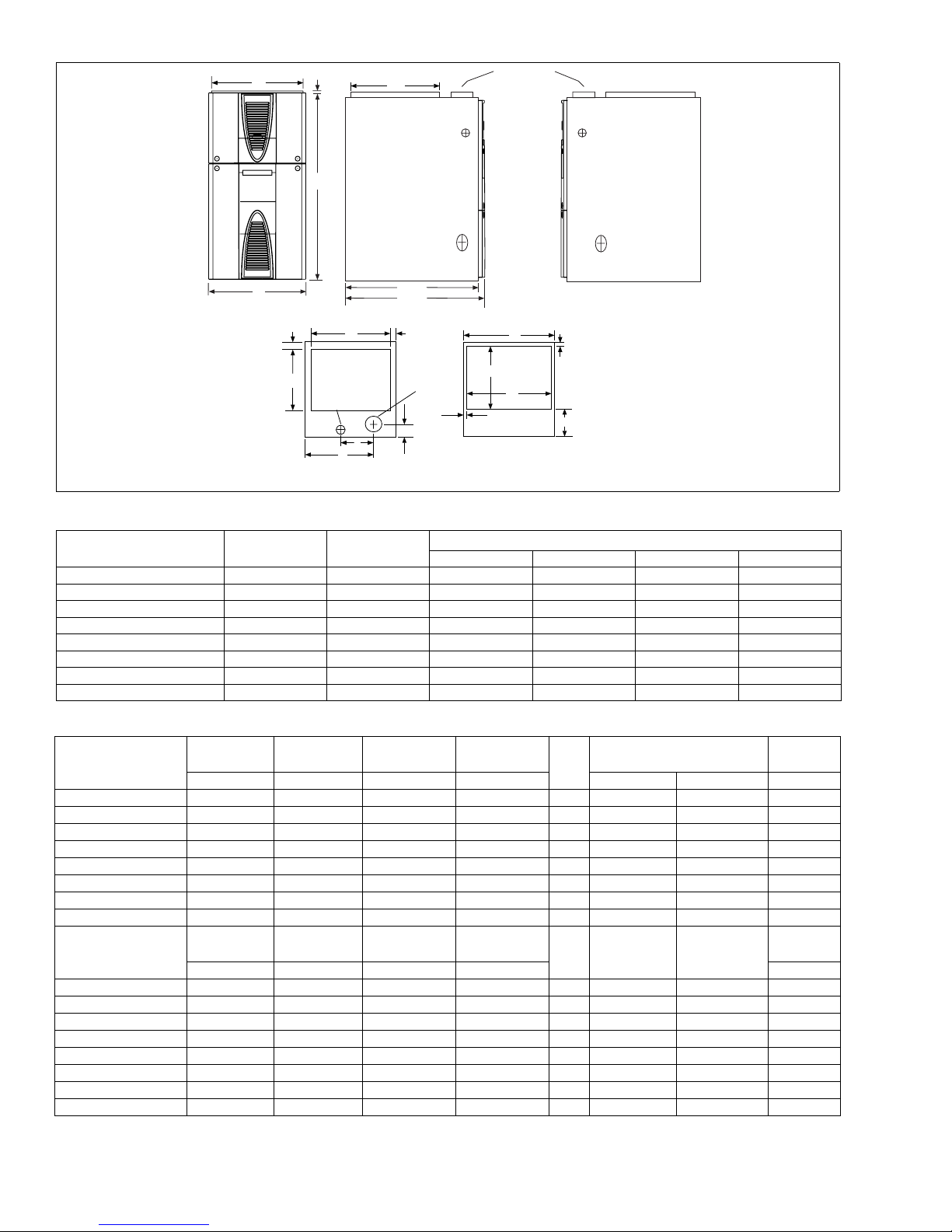
CABINET AND DUCT DIMENSIONS
MODEL
Airflow
CFM
Cabinet
Size
A(in.) B(in.) C(in.) D(in.)
PT8A12(N,L)040DH11 1200 A 14 1/2 13 1/4 12 10 3/8
PT8A12(N,L)060DH11 1200 A 14 1/2 13 1/4 12 10 3/8
PT8A12(N,L)080DH11 1200 A 14 1/2 13 1/4 12 10 3/8
PT8B16(N,L)080DH11 1600 B 17 1/2 16 1/4 15 11 3/4
PT8C16(N,L)080DH11 1600 C 21 19 3/4 18 1/2 13 1/2
PT8B12(N,L)100DH11 1200 B 17 1/2 16 1/4 15 11 3/4
PT8C16(N,L)100DH11 1600 C 21 19 3/4 18 1/2 13 1/2
PT8C20(N,L)120DH11 2000 C 21 19 3/4 18 1/2 13 1/2
CABINET DIMENSION
RATINGS & PHYSICAL / ELECTRICAL DATA
Input
MODEL
High/Low
MBH MBH CFM In Hp Amps In
PT8A12(N,L)040DH11 57/42 46/34 1200 14-1/2 80.0 1/2 7.7 10 x 8
PT8A12(N,L)060DH11 80/59 64/48 1200 14 1/2 80.0 1/2 7.7 10 x 8
PT8A12(N,L)080DH11 80/59 64/48 1600 17-1/2 80.0 3/4 9.6 10 x 10
PT8B16(N,L)080DH11 80/59 64/48 1600 21 80.0 3/4 9.6 10 x 10
PT8C16(N,L)080DH11 100/65 80/53 1600 17 1/2 80.0 3/4 9.6 10 x 10
PT8B12(N,L)100DH11 100/65 80/53 1600 21 80.0 3/4 9.6 10 x 10
PT8C16(N,L)100DH11 100/65 80/53 2000 21 80.0 1 12.8 11 x 10
PT8C20(N,L)120DH11 120/78 96/64 2000 21 80.0 1 12.8 11 x 10
Input/Cabinet
MODEL
High/Low
MBH °F °F °F Lbs
PT8A12(N,L)040DH11 57/42 165 25-55 35-65 9.0 20 14 107
PT8A12(N,L)060DH11 80/52 170 40-70 40-70 9.0 20 14 117
PT8A12(N,L)080DH11 80/59 155 25-55 25-55 12.0 20 14 129
PT8B16(N,L)080DH11 80/59 155 25-55 25-55 12.0 20 14 140
PT8C16(N,L)080DH11 100/65 170 40-70 40-70 12.0 20 14 128
PT8B12(N,L)100DH11 100/65 170 40-70 40-70 12.0 20 14 140
PT8C16(N,L)100DH11 100/65 170 40-70 40-70 14.0 20 12 145
PT8C20(N,L)120DH11 120/78 165 35-65 35-65 14.0 20 12 147
Wire size and over current protection must comply with the National Electrical Code (NFPA-70-latest edition) and all local codes.
The furnace shall be installed so that the electrical components are protected from water.
Annual Fuel Utilization Efficiency (AFUE) numbers are determined in accordance with DOE Test procedures.
Output BTU/H
High/Low
Max. Outlet
Air Temp
Nominal
Airflow
Low Fire Air
Temp. Rise
Cabinet
Width
High Fire
Air Temp. Rise
AFUE
Unit
Amps
Blower
Max
Over-Current
Protect
Min. wire Size
(awg) @ 75 ft
one way
Blower
Size
Operation
Weight
2 Unitary Products Group
Page 3
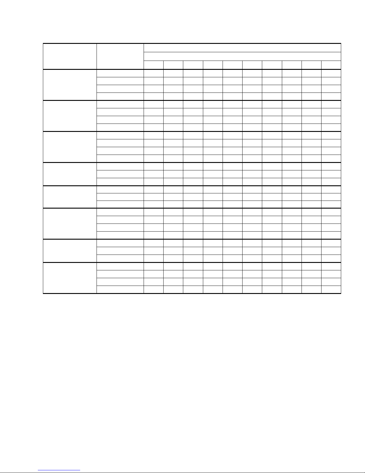
BLOWER PERFORMANCE CFM - (WITHOUT FILTER)
MODELS Speed
0.10.20.30.40.50.60.70.80.91.0
High
PT8A12(N,L)040DH11
Medium High
Medium Low
Low
High 1500 1470 1390 1320 1240 1170 1070 960 830 700
PT8A12(N,L)060DH11
Medium High 1380 1340 1280 1210 1150 1060 970 870 760 610
Medium Low 1220 1200 1160 1110 1050 990 910 820 700 600
Low 960 950 940 920 890 840 770 710 630 530
High 1550 1480 1410 1330 1250 1150 1050 940 810 700
PT8A12(N,L)080DH11
Medium High 1400 1360 1290 1220 1150 1060 970 860 730 590
Medium Low 1230 1210 1170 1120 1060 990 910 810 680 560
Low 980 970 960 930 890 830 760 680 550 450
High 2070 2000 1930 1850 1770 1670 1580 1470 1360 1250
PT8B16(N,L)080DH11
Medium 1650 1630 1610 1560 1490 1420 1360 1270 1170 1040
Low 1410 1400 1370 1340 1320 1270 1210 1140 1050 950
High 1895 1812 1736 1624 1544 1437 1311 1153 1032 836
PT8C16(N,L)080DH11
Medium 1726 1645 1581 1491 1412 1311 1192 1049 908 750
Low 1561 1493 1430 1373 1304 1199 1089 967 816 699
High 1710 1650 1580 1510 1420 1330 1260 1160 1090 930
PT8B12(N,L)100DH11
Medium High 1480 1440 1380 1330 1270 1180 1090 980 790 630
Medium Low 1240 1230 1200 1170 1110 1030 950 850 710 600
Low 980 980 980 970 930 890 800 720 630 530
High
PT8C16(N,L)100DH11
Medium
Low
High 2400 2310 2220 2120 2010 1910 1800 1660 1520 1350
PT8C20(N,L)120DH11
Medium High 2090 2030 1970 1880 1790 1730 1640 1520 1370 1190
Medium Low 1720 1690 1650 1600 1550 1460 1370 1270 1150 980
Low 1440 1430 1400 1340 1280 1220 1140 1040 930 830
NOTES:
1. Airflow expressed in standard cubic feet per minute (CFM).
2. Motor voltage at 115 V.
1620 1590 1480 1400 1310 1240 1140 1040 910 760
1430 1390 1340 1280 1220 1140 1050 960 820 710
1210 1210 1190 1200 1100 1020 940 850 730 620
980 980 970 950 920 870 810 720 620 520
2210 2160 2100 2030 1940 1850 1750 1640 1520 1400
1640 1640 1620 1590 1530 1500 1430 1360 1270 1160
1410 1410 1370 1360 1300 1260 1210 1150 1090 1010
246796-YTG-D-0407
Airflow Data
Ext. Static Pressure
Unitary Products Group 3
Page 4
246796-YTG-D-0407
HORIZONTAL SIDEWALL VENTING
For applications where vertical venting is not possible, the
only approved method of horizontal venting is the use of an
auxiliary power vent. Approved power venters are Fields
Controls Model SWG-4Y or the appropriate Tjernlund GPAK
model. Follow all application and installation details provided
by the manufacturer of the power vent. This unit may be horizontally vented using 4” (10.2 cm) diameter pipe with a minimum length of 4.5 feet (1.37 m) and a maximum length of
34.5 feet (10.82 m) with up to 4 elbows.
FILTER PERFORMANCE
The airflow capacity data published in Blower Performance
Tables above, represents blower performance WITHOUT filters. To determine the approximate blower performance of
the system, apply the filter drop value for the filter being used
or select an appropriate value from the Table below.
NOTE: The filter pressure drop values in Blower Performance T ables are typical values for the type of filter listed and
should only be used as a guideline. Actual pressure drop ratings for each filter type vary between filter manufacturer.
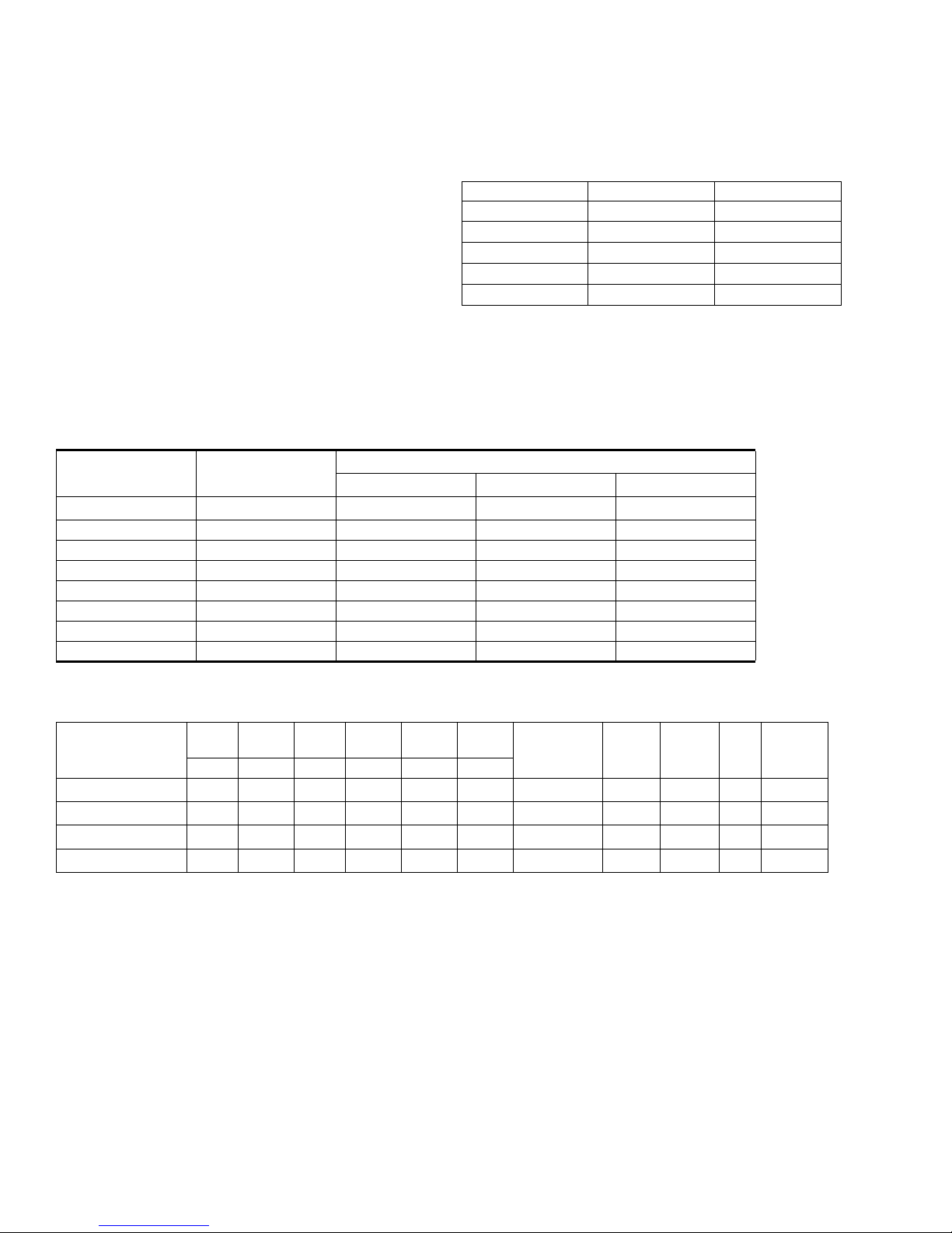
RECOMMENDED FILTER SIZES
CFM Cabinet Size Top Return (in)
1200 A (2) 14 x 20
1600 B (2) 14 x 20
1200 B (2) 14 x 20
1600 C (2) 14 x 20
2000 C (2) 14 x 20
NOTES:
1. Air velocity through throwaway type filters may not exceed 300
feet per minute. All velocities over this require the use of high
velocity filters.
FILTER PERFORMANCE - PRESSURE DROP INCHES W.C. AND (KPA)
Airflow Range
CFM
0 - 750 230 0.01 0.01 0.15
751 - 1000 330 0.05 0.05 0.20
1001 - 1250 330 0.10 0.10 0.20
1251 - 1500 330 0.10 0.10 0.25
1501 - 1750 380 0.15 0.14 0.30
1751 - 2000 380 0.19 0.18 0.30
2001 & Above 463 0.19 0.18 0.30
Minimum
Opening Size
2
in
Disposable Washable Fiber Pleated
In W.C. In W.C. In W.C.
Filter Type
UNIT CLEARANCES TO COMBUSTIBLES
Application
Downflow 160036
Downflow B-Vent 1 3 0 0 0 1
Horizontal 1 6 0 0 3 6 Combustible No Yes Yes
Horizontal B-Vent 1 3 0 0 0 1 Combustible No Yes Yes
1 Special floor base or air conditioning coil required for use on combustible floor.
2 Line contact only permitted between lines formed by the intersectio n of the rear panel and side panel (top in horizontal position) of the furnace
jacket and building joists, studs or framing.
Top Front Rear
In. In. In. In. In. In.
Left
Side
Right
Side
Flue
Floor/
Bottom
1
1
1
1
Closet Alcove Attic
Yes Yes Yes No
Yes Yes Yes No
Line
Contact
2
Yes
2
Yes
4 Unitary Products Group
Page 5

246796-YTG-D-0407
APPLYING FILTER PRESSURE DROP TO
DETERMINE SYSTEM AIRFLOW
To determine the approximate airflow of the unit with a filter in
place, follow the steps below:
1. Select the filter type.
2. Select the number of return air openings or calculate the
return opening size in square inches to determine the
proper filter pressure drop.
3. Determine the External System Static Pressure (ESP)
without the filter.
4. Select a filter pressure drop from the table based upon
the number of return air openings or return air opening
size and add to the ESP from Step 3 to determine the
total system static.
5. If total system static matches an ESP value in the airflow
table (i.e. 0.20, 0.60, etc,) the system airflow corresponds to the intersection of the ESP column and Model/
Blower Speed row .
6. If the total system static falls between ESP values in the
table (i.e. 0.58, 0.75, etc.), the static pressure may be
rounded to the nearest value in the table determining the
airflow using Step 5 or calculate the airflow by using the
following example.
Example: For a 60,000 Btuh furnace operating on high
speed blower, it is found that total system static is 0.58" w.c.
To determine the system airflow, complete the following
steps:
1. Obtain the airflow values at 0.50" & 0.60" ESP.
Airflow @ 0.50": 1240 CFM
Airflow @ 0.60": 1170 CFM
2. Subtract the airflow @ 0.50" from the airflow @ 0.60" to
obtain airflow difference.
1170 - 1240 = -70 CFM
3. Subtract the total system static from 0.50" and divide this
difference by the difference in ESP values in the table,
0.60" - 0.50", to obtain a percentage.
(0.58 - 0.50) / (0.60 - 0.50) = 0.8
4. Multiply percentage by airflow difference to obtain airflow
reduction.
(0.8) x (-70) = -56
5. Subtract airflow reduction value from airflow @ 0.50" to
obtain actual airflow @ 0.58" ESP.
1240 - 56 = 1184
ACCESSORIES
PROPANE (LP) CONVERSION KIT -
1NP0347 - All Models
These accessory conversion kits may be used to convert natural gas (N) units for propane (LP) operation. Conversions
must be made by qualified distributor or dealer personnel.
COMBUSTIBLE FLOOR BASE -
1CB0314 - for 14-1/2” cabinet models
1CB0317 - for 17-1/2” cabinet models
1CB0321 - for 21” cabinet models
HIGH ALTITUDE PRESSURE SWITCHES -
For installation where the altitude is less than 8,000 feet it is
not required that the pressure switch be changed. For altitudes above 8,000 feet see kits below. Conversion must be
made by qualified distributor or dealer personnel.
1PS0313 - 040, 060, 080, 100 MBH
1PS0314 - 120 MBH
ROOM THERMOSTATS - A wide selection of compatible
thermosets are available to provide optimum performance
and features for any installation.
1H/1C, manual change-over electronic non-programmable
thermostat.
1H/1C, auto/manual changeover, electronic programmable,
deluxe 7-day, thermostat.
1H/1C, auto/manual changeover, electronic programmable.
* For the most current accessory information, refer to the
price book or consult factory.
Unitary Products Group 5
Page 6
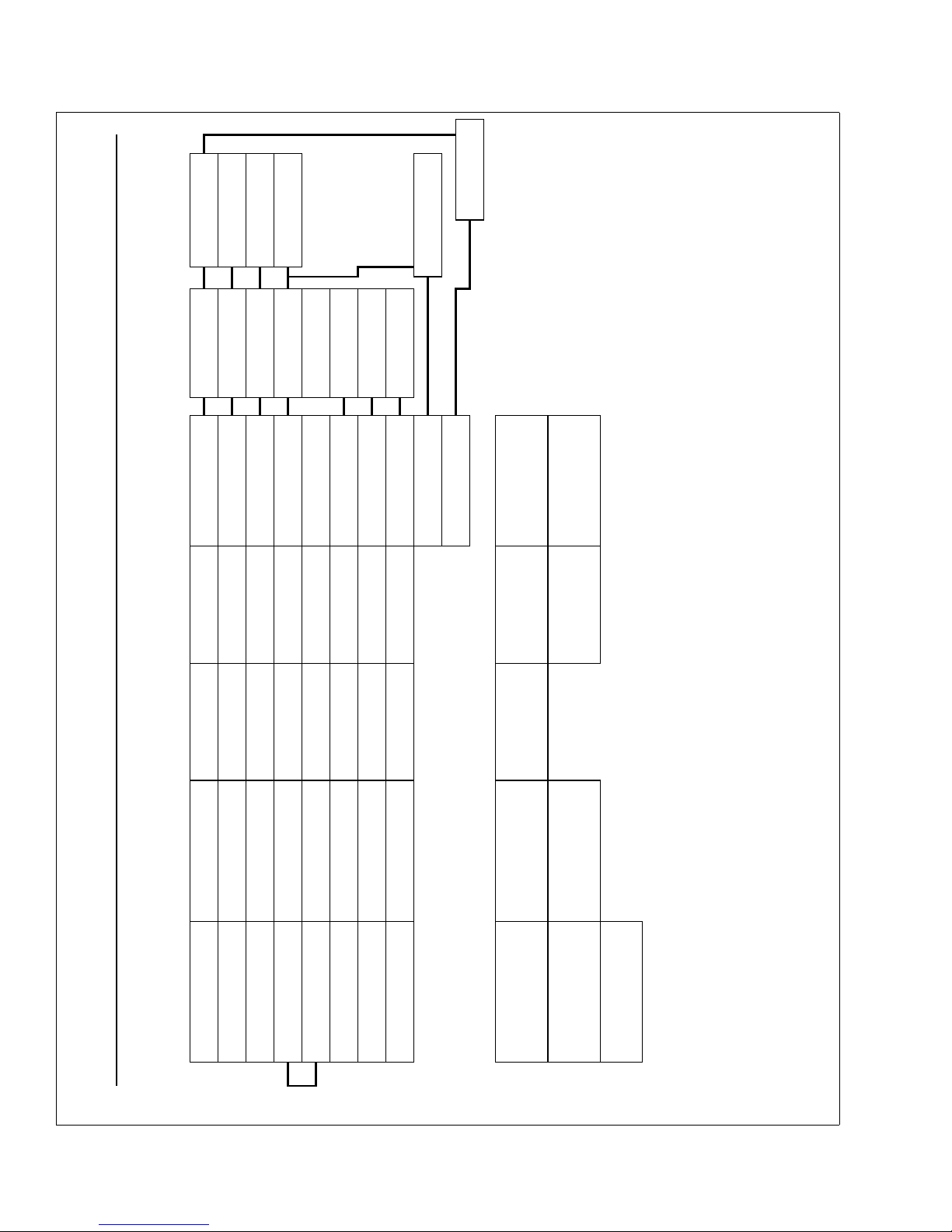
246796-YTG-D-0407
For additional connection diagrams for all UPG equipment refer to “Low Voltage System Wiring” document available online at
www.upgnet.com in the Product Catalog Section.
(Optional)
C
TWO STAGE
24-Volt Common
AIR CONDITIONING
Y1
Y2
First Stage Cool
Second Stage Cool
R
24-Volt Hot
24V HUMIDIFIER
Interface
Comfort Alert
C
2 STAGE PSC
24-Volt Common
FURNACE CONTROL
C
*PP32U72124
THERMOSTAT
24-Volt Common
C
*DP22U70124
THERMOSTAT
24-Volt Common
C
*DN22C00124 *PP32U71124
THERMOSTAT
24-Volt Common
Y1
First Stage Cool
Single/Second Stage
Y1
Y2
First Stage Cool
Second Stage Cool
Y2
Y1
First Stage Cool
Second Stage Cool
Y
Y2
First Stage Cool
Second Stage Cool
R
24-Volt Hot
R
24-Volt Hot
R
24-Volt Hot
R
24-Volt Hot
G
W2
W/W1
Single/First Stage Heat
E/W1
First Stage Heat
E/W1
First Stage Heat
W
First Stage Heat
Fan
Second Stage Heat
G
W2
Fan
Second Stage Heat
G
W2
Fan
Second Stage Heat
G
W2
Fan
Second Stage Heat
L
HM
Humidistat
Malfunction Light
to MLTI STG
Step 1 of Thermostat User
Configuration Menu must be set
batteries
Connection of the "C"
is optional when used with
Termainal, 24-Volt Common,
batteries
Connection of the "C"
is optional when used with
Termainal, 24-Volt Common,
Features
to ON to use Comfort Alert
Step 16 of Thermostat User
Configuration Menu must be set
set to MS 2
Step 1 of Thermostat User
Configuration Menu must be
C
*PP32U70124
THERMOSTAT
C
*DN22U00124
THERMOSTAT
Y
24-Volt Common
Y
24-Volt Common
R
Y2
First Stage Cool
Second Stage Cool
R
Y2
First Stage Cool
Second Stage Cool
RC
24-Volt Hot (Heat XFMR)
RC
24-Volt Hot (Heat XFMR)
AC9 2 Stage Scroll A/C w/2 Stage Furnace, 2 Stage Cooling Ready- PT8/9; (F,L)*8/9T, (G,L)*8/9T, XYG8S-U, XYF8S-U / XYF8S-U*L
Thermostat Chart - AC
6 Unitary Products Group
G
W2
E/W1
First Stage Heat
24-Volt Hot (Cool XFMR)
E/W1
First Stage Heat
24-Volt Hot (Cool XFMR)
Fan
Second Stage Heat
G
W2
Fan
Second Stage Heat
when used with batteries
24-Volt Common, is optional
Connection of the "C" Termainal,
when used with batteries
24-Volt Common, is optional
Connection of the "C" Termainal,
Multistage Conventional
Thermostat Installer Setup
Number 0170 - System Type -
must be set to 8 - 2 Heat/2 Cool
must be set to 6 -
Number 1 - System Type -
Thermostat Installer Setup
Number 15 - Compressor
Thermostat Installer Setup
2 Heat/2 Cool Conventional
Protection - must be set to 5
Page 7
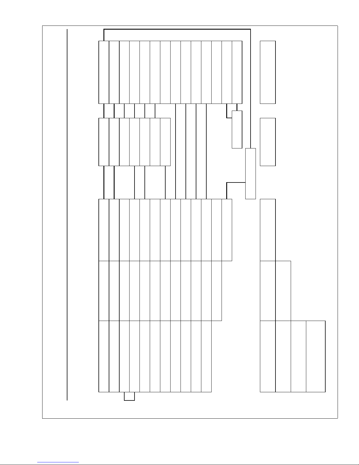
246796-YTG-D-0407
C
HEAT PUMP
TWO STAGE
C
PSC-2 STAGE
COOLING READY
FURNACE CONTROL
C
*PP32U72124
*PP32U71124
Y1
Y2 OUT
24-Volt Common
First Stage Heat/Cool
Second Stage Cool Output
Y1
Y/Y2
First Stage Cool
24-Volt Common
Single/Second Stage Cool
Y1
24-Volt Common
First Stage Heat/Cool
R
W2 OUT
W1 OUT
24-Volt Hot
First Stage Auxiliary Heat Output
Second Stage Auxiliary Heat Output
R
R
W2
W/W1
24-Volt Hot
Second Stage Heat
Single/First Stage Heat
DHM
24-Volt Hot
Dehumidistat
O
X/L
Y2
Malfunction Light
Reversing Valve–Energized in Cool
G
Fan
L
O
G
Fan
Y2
Malfunction Light
Reversing Valve–Energized in Cool
W
BSG
Auxiliary Heat
Bonnet Sensor
Second Stage Heat/Cool
HM
W2
E/W1
Second Stage Heat/Cool
First Stage Auxiliary Heat
Humidistat
Second Stage Auxiliary Heat
BS
Bonnet Sensor
(Optional)
Bonnet Sensor
(Optional)
24V HUMIDIFIER
Heat Pump to ON
Change FFuel Jumper on
Set W2 Delay on furnace to OFF
Menu must be set to Heat Pump 2
Step 1 of Thermostat User Configuration
C
Y1
*DP22U70124
24-Volt Common
First Stage Heat/Cool
Y
C
*PP32U70124 *DN22H00124
THERMOSTAT THERMOSTAT THERMOSTAT
24-Volt Common
First Stage Heat/Cool
W/031-01996- Series Demand Control; Hot Heat Pump Mode OR Conventional
HP23 Two Stage H/P - H*5B, YZE - w/Two Stage Furnace, 2 Stage Cooling Ready - PT8/9, (F,L)*8/9T, (G,L)*8/9T, XYG8S-U, XYF8S-U / XYF8S-U*L
Thermostat Chart - HP
Unitary Products Group 7
R
24-Volt Hot
E
R
RC
Emergency Heat
24-Volt Hot (Cool XFMR)
24-Volt Hot (Heat XFMR)
G
Fan
Y2
L
O
Malfunction Light
Reversing Valve–Energized in Cool
Fan
O/B
L
Y2
Reversing Valve
Malfunction Light
G
W2
E/W1
Second Stage Heat/Cool
First Stage Auxiliary Heat
Second Stage Auxiliary Heat
AUX
Auxiliary Heat
Second Stage Heat/Cool
set to Heat Pump 2
thermostat not necessary
Step 1 of Thermostat User
Configuration Menu must be
Selection of GAS/ELEC switch on
12 - 3 Heat/2 Cool Heat Pump
- System Type - must be set to
Thermostat Installer Setup Number 0170
- O/B Terminal Energized in Cooling
Thermostat Installer Setup Number 0200
Thermostat Installer Setup Number 0190 -
Reversing Valve (O/B) Operation - must be set to 0
Pump Backup Heat Source is Fossil Fuel
Thermostat Installer Setup Number 0210 -
External Fossil Fuel Kit - must be set to 0 -
- Backup Heat Source - must be set to 1 - Heat
Heat Pump Backup Heat
External Fossil Fuel Kit is Controlling
Page 8

NOTES
Subject to change without notice. Printed in U.S.A. 246796-YTG-D-0407
Copyright © by York International Corp. 2007. All rights reserved. Supersedes: 246796-YTG-C-0806
Unitary 5005 Norman
Products York OK
Group Drive 73069
 Loading...