

Page 1
TECHNICAL GUIDE
SINGLE PIECE STANDARD ECM
AIR HANDLERS
FOR USE WITH SPLIT-SYSTEM
COOLING & HEA T PUMPS
MODELS: AHE18 THRU 60*
Due to continuous product improvement,
specifications are subject to change without notice.
Visit us on the web at:
www.upgnet.com and www.york.com
Additional rating information can be found at:
www.ahridirectory.org
WARRANTY
Standard 5-year limited parts warranty.
Extended 10-year limited parts warranty when product is
registered online within 90 days of purchase for replacement or closing for new home construction.
ISO 9001
Certified Quality
Management System
1169652-YTG-A-1114
DESCRIPTION
The AHE Air Handler line offers the ultimate in comfort, sound
and application flexibility. This unit may be used for upflow,
downflow, horizontal right, or horizontal left applications. No
special kits are required to install this deluxe product.
All JCI Unitary Products air handlers and coils use a TXV to provide our customers with the optimum performance and refrigerant control. Air handlers are shipped with “Flex-coils” without a
factory installed metering device. For added flexibility, an R-22
or R-410A TXV or orifice can be field installed to meet your
refrigerant choice.
FEATURE
Thermal Expansion Valve - Provides the ultimate refrigerant
control required for today’s high efficient product. The UPG bolton TXV provides easy installation to convert the air handler to
the required refrigerant, which is a true bolt-on design that does
not require brazing to replace or install.
Insulated Cabinet - All air handler cabinets are thermally insulated with 3/4” foil faced insulation to prevent sweating.
Factory Sealed - Achieves 2% or less total airflow leakage rate
at duct blaster field test conditions for system airflow verification.
Durable Finish Inside and Out - Air handler casings are made
of pre-painted galvanized steel which provides a better paint to
steel bond that resists corrosion and rust creep. All internal coil
sheet metal parts are made of G60 galvanized or prepainted
G30 galvanized.
Filters - All models have internal filter racks provided for use
with 1” thick standard size filters.
Electric Heat Kits - 6HK series of field installed electric heat
kits are available for installation friendly and easy service applications.
High Efficiency Blowers - All models use high efficiency
brushless DC motors to provide cooling SEER rating enhancement.
FOR DISTRIBUTION USE ONLY - NOT TO BE USED AT POINT OF RETAIL SALE
Page 2
1169652-YTG-A-1114
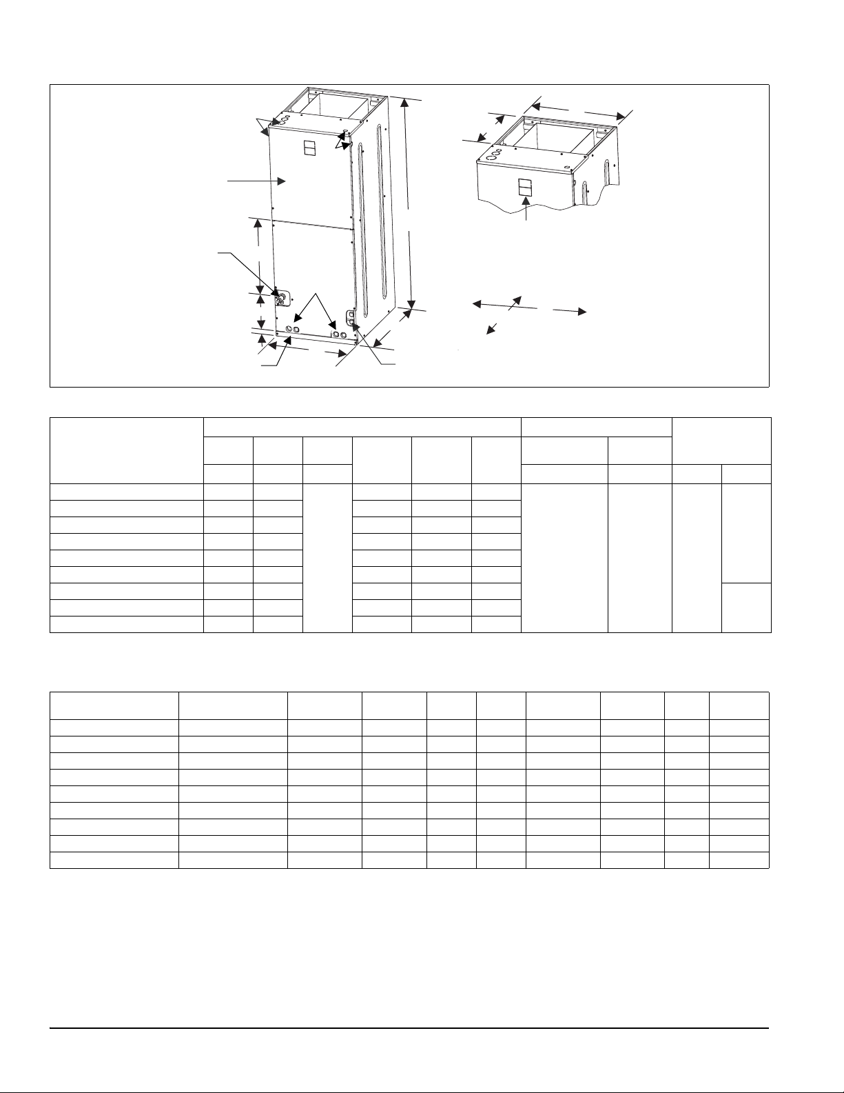
J
D
Blower
Compartment
Service
Disconnect
Panel
Drain Pan Connections
for Horizontal Applications
Refrigerant
Connections
Drain Connections
for Upflow
Applications
7-11/32”
B
A
K
C
1-1/2”
Top Outlet
Dimensions
Filter
Access
20-5/16”
E
Bottom Inlet
Dimensions
13”
F
A024-001
DIMENSIONS & DUCT CONNECTION DIMENSIONS
Dimensions
Dimensions Wiring Knockouts Refrigerant
Models
AHE18B3X(H,T)21 46” 17 1/2”
AHE22B3X(H,T)21 46” 17 1/2” 16 1/2” 13-29/32" 16 1/2”
AHE24B3X(H,T)21 46” 17 1/2” 16 1/2” 13-29/32" 16 1/2”
AHE30B3X(H,T)21 46” 17 1/2” 16 1/2” 13-29/32" 16 1/2”
AHE34C3X(H,T)21 52” 21” 21 1/2” 17-13/32" 20”
AHE36C3X(H,T)21 52” 21” 21 1/2” 17-13/32" 20”
AHE42D3X(H,T)21 57’ 24 1/2” 26” 20-29/32" 23-1/2”
AHE60D3X(H,T)21 57” 24 1/2” 26” 20-29/32" 23-1/2”
1. Actual size (Conduit size).
ABC
DEF
Height Width Depth Power Control Liquid Vapor
16 1/2” 13-29/32" 16 1/2”
21 1/2”
JK
7/8" (1/2")
1-3/8"(1")
1
7/8" (1/2") 3/8"
1-23/32" (1-1/4")
Connections
Line Size
3/4"
7/8"AHE48D3X(H,T)21 57” 24 1/2” 26” 20-29/32" 23-1/2”
COIL TECHNICAL DATA
Models Application
Refrig.
Conn. Types
AHE18B3X(H,T)21 Cooling /Heat Pump Sweat 3.4 2 14 (2) 14 x 17.5 1 x 0.866 3/8 Enhanced
AHE22B3X(H,T)21 Cooling /Heat Pump Sweat 3.9 2 14 (2) 16 x 17.5 1 x 0.866 3/8 Enhanced
AHE24B3X(H,T)21 Cooling /Heat Pump Sweat 3.9 3 12 (2) 16 x 17.5 1 x 0.866 3/8 Enhanced
AHE30B3X(H,T)21 Cooling /Heat Pump Sweat 3.9 3 12 (2) 16 x 17.5 1 x 0.866 3/8 Enhanced
AHE34C3X(H,T)21 Cooling /Heat Pump Sweat 3.9 3 12 (2) 16 x 17.5 1 x 0.866 3/8 Enhanced
AHE36C3X(H,T)21 Cooling /Heat Pump Sweat 4.9 3 12 (2) 20 x 17.5 1 x 0.866 3/8 Enhanced
AHE42D3X(H,T)21 Cooling /Heat Pump Sweat 5.4 3 12 (2) 22 x 17.5 1 x 0.866 3/8 Enhanced
AHE48D3X(H,T)21 Cooling /Heat Pump Sweat 5.8 3 11 (2) 24 x 17.5 1 x 0.866 3/8 Enhanced
AHE60D3X(H,T)21 Cooling /Heat Pump Sweat 6.8 3 12 (2) 28 x 17.5 1 x 0.866 3/8 Enhanced
2 Johnson Controls Unitary Products
Face Area
(Sq. Ft.)
Rows
Deep
Fins
Per In.
Coil Size
Tube
Geometry
Tube
Dia.
Fin
Type
Page 3
1169652-YTG-A-1114
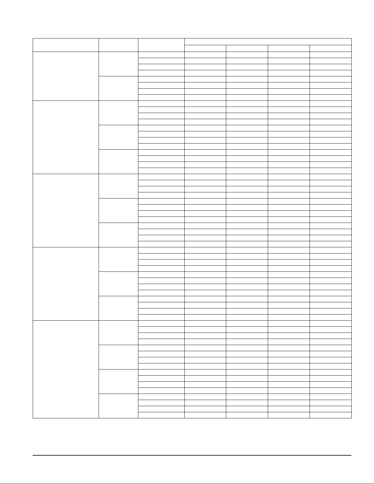
COOLING CAPACITY
Models
AHE18B
AHE22B
AHE24B
AHE30B
AHE34C
For notes see Page 4.
1
Rated CFM
610
850
585
795
985
585
795
985
585
795
985
730
855
1000
1190
Entering Air
2
Dry/Wet Bulb (°F)
MBH@ Evap. Temp. and Corresponding R-410A Pressure (°F/PSIG)
35/107.9 40/118.9 45/130.7 50/143.3
85/72 37.9 33.7 28.3 23.3
80/67 31.8 27 22.5 17.6
75/62 26.4 21.5 16.7 11.6
70/57 20.7 18.4 15.8 13.5
85/72 49.7 43.2 36.9 28.4
80/67 42.1 35.1 28.8 22.5
75/62 33.7 28 21.4 14.7
70/57 26.5 23.8 20.3 16.9
85/72 37.9 33.8 29 24.4
80/67 31.7 27.7 23 22.8
75/62 26.4 22.1 19.5 15.8
70/57 20.2 18.4 16 13.5
85/72 47.7 42.6 35.3 30.3
80/67 40.1 34.7 28.9 22.8
75/62 32.7 27.1 24.7 19.1
70/57 25.7 23.5 20.5 17.1
85/72 55.5 47.5 41.6 34.4
80/67 45.8 40.1 32.5 22.8
75/62 38.1 31.7 28.2 23.2
70/57 29.9 27.8 23.9 20.3
85/72 38.7 34.4 30.1 24.7
80/67 33.6 28.9 23.9 18.9
75/62 27.2 22.7 17.8 12.8
70/57 21.2 18.6 16.2 13.7
85/72 50.8 45.2 38.4 32.0
80/67 43.7 36.8 31 24.0
75/62 35.7 29.5 23.1 16.1
70/57 27.9 24.5 21 17.6
85/72 64.9 54 45.6 37.8
80/67 52.3 44.6 36.9 28.4
75/62 42.2 35.2 26.8 19.3
70/57 33.6 29.6 25.4 21.4
85/72 49.4 44 37.6 31.3
80/67 42 36.4 29.5 22.9
75/62 34 28.4 25.1 20.2
70/57 26.6 23.9 20.7 17.5
85/72 55.5 50.4 42.1 35.2
80/67 48 40.3 33.3 26.4
75/62 38.8 32.5 28.6 23.1
70/57 30.6 28 23.8 19.9
85/72 63.3 56.3 48.3 40.1
80/67 54.2 46.4 38.3 29.8
75/62 43.8 36.3 32.9 26.4
70/57 34.4 31.7 27.4 23.0
85/72 71.3 63.5 55.1 44.8
80/67 61.3 53.1 43.5 33.7
75/62 49.8 40.3 37.5 30.2
70/57 38.8 36.5 31.5 26.7
Johnson Controls Unitary Products 3
Page 4
1169652-YTG-A-1114
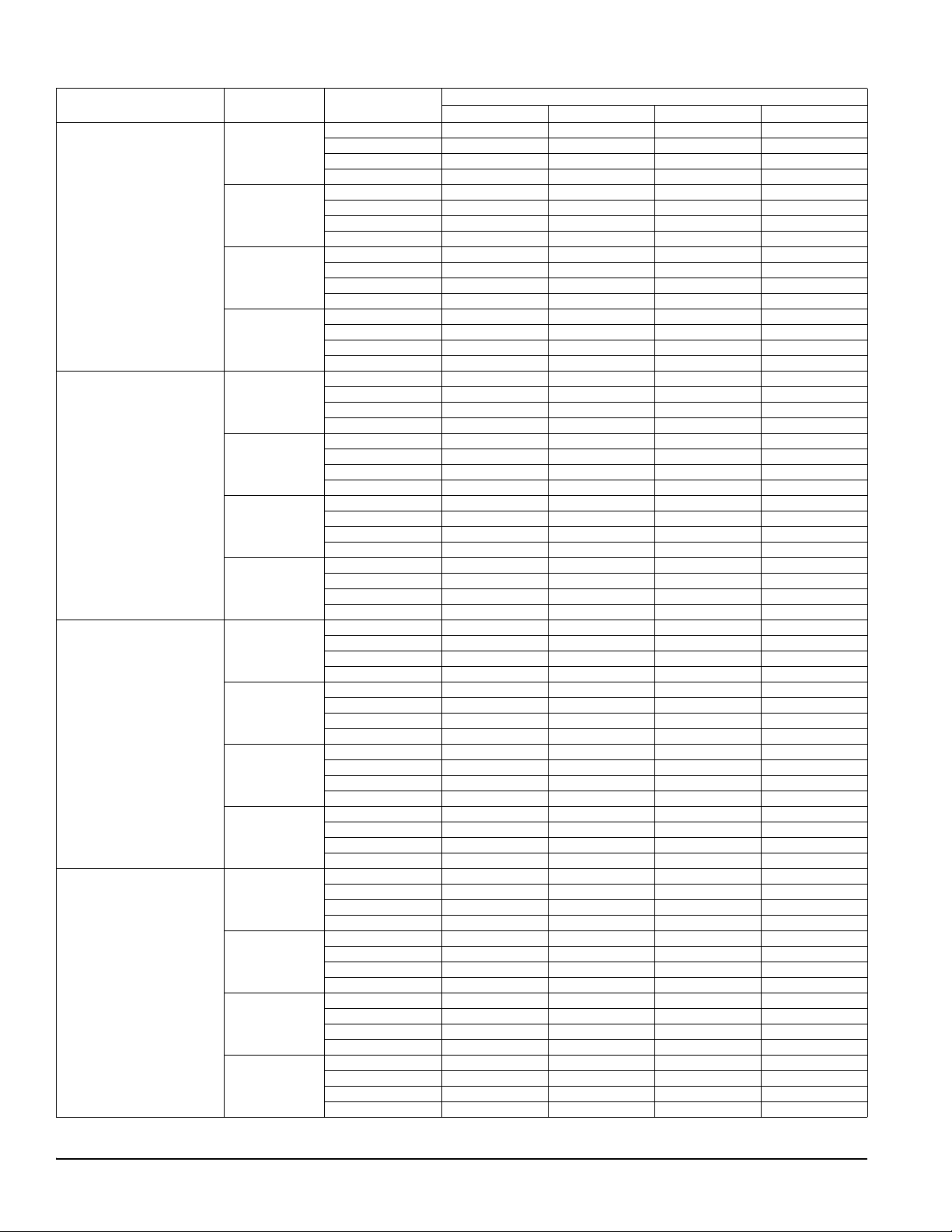
COOLING CAPACITY1 (Continued)
Entering Air
730
855
1000
1190
820
1000
1180
1385
1000
1195
1385
1600
1190
1390
1565
1835
2
Dry/Wet Bulb (°F)
85/72 49.3 45.2 38.3 31.4
80/67 43 37.3 31 24.0
75/62 34.7 28.8 22.8 16.2
70/57 26.8 23.4 20.4 16.9
85/72 59.1 51 44.1 36.5
80/67 49.3 42.4 35.4 27.6
75/62 39.9 33.1 26.1 18.2
70/57 31.1 26.9 23.5 19.7
85/72 65.2 59.5 51.2 41.3
80/67 56.4 48.3 39.9 31.3
75/62 45.8 38.1 29.7 20.8
70/57 35.7 31.2 26.9 22.6
85/72 67.5 65.9 59.8 48.7
80/67 64.9 56.7 46.2 35.7
75/62 53.5 43.2 34.1 24.0
70/57 41.4 36.6 31.5 26.2
85/72 56.6 51.1 42.8 35.6
80/67 48.6 41.1 34.8 27.6
75/62 39.4 33 26 18.3
70/57 30.5 26.6 23.1 19.6
85/72 65.7 61 52.7 42.9
80/67 58 49.6 41.1 32.1
75/62 46.7 38.9 30.4 21.8
70/57 36.4 31.6 27.6 23.3
85/72 67.9 71.4 60.2 48.8
80/67 65.6 56.9 47.1 37.1
75/62 53.8 45.2 34.7 24.6
70/57 42.2 37.1 31.9 27.0
85/72 69.4 81 68 57.2
80/67 77.1 65.4 54.1 41.6
75/62 62.1 51 39.8 28.1
70/57 48.1 42.5 36.8 30.6
85/72 69 59.8 51.3 41.5
80/67 56.5 48.2 39.7 29.9
75/62 45.1 36.8 28.3 18.9
70/57 34.4 31 26.8 22.5
85/72 79.5 69.7 59.9 48.6
80/67 65.2 55.5 45.5 34.9
75/62 52.2 42.5 32.6 21.8
70/57 40.1 36.1 31.1 26.2
85/72 90 78.1 66 54.5
80/67 73.5 62.7 51.3 38.7
75/62 59.2 48.2 36.9 24.0
70/57 45.2 41 35.4 29.7
85/72 102.2 90 74.3 60.4
80/67 83.6 70.6 57.2 43.1
75/62 66.1 54 41.2 27.0
70/57 50.7 46.1 39.8 33.4
85/72 83.6 73.7 62.9 51.6
80/67 68.2 58.4 48.4 37.1
75/62 54.9 45.3 34.8 23.9
70/57 42.2 37.3 31.9 26.9
85/72 95.9 84.1 71.9 58.8
80/67 79.2 67.4 54.4 41.6
75/62 62.4 51.2 39.7 26.9
70/57 48 42.5 36.8 30.6
85/72 106.3 94.2 78.5 63.5
80/67 87.6 73.9 60.2 45.9
75/62 69.3 56.8 43.5 29.7
70/57 53.1 46.9 40.5 34.1
85/72 122.1 107.1 90.9 72.6
80/67 100.2 85.9 69.8 51.8
75/62 79.7 65.3 49.8 32.9
70/57 60.8 54.1 46.4 38.7
Models
Rated CFM
AHE36C
AHE42D
AHE48D
AHE60D
1. Actual capacity varies with the outdoor AC or HP that is used with the system.
2. Airflow is calculated for each system tonnage.
MBH@ Evap. Temp. and Corresponding R-410A Pressure (°F/PSIG)
35/107.9 40/118.9 45/130.7 50/143.3
4 Johnson Controls Unitary Products
Page 5

1169652-YTG-A-1114
APPLICATION FACTORS - RATED CFM VS. ACTUAL CFM
% Of Rated Airflow (CFM)
Capacity Factor
80% 90% 100% 110% 120%
0.96 0.98 1.00 1.02 1.03
PHYSICAL & ELECTRICAL DATA - COOLING ONLY
Models
AHE18B
(6ELE6)
AHE22B
Blower - Diameter x Width 10 x 8 10 x 8 10 x 8 10 x 8 11 x 10 11 x 10 11 x 10 11 x 10 11 x 10
Motor
HP 1/3 HP 1/3 HP 1/3 HP 1/3 HP 1/2 HP 1/2 HP 1/2 HP 3/4 HP 3/4 HP
Nominal RPM 1050 1050 1050 1050 1050 1050 1050 1050 1050
Voltage 208/230 208/230 208/230 208/230 208/230 208/230 208/230 208/230 208/230
Full Load Amps @230V
2.8 2.8 2.8 2.8 4.1 4.1 4.1 6.0 6.0
Type DISPOSABLE OR PERMANENT
1
Filter
Size 16 x 20 x 1 16 x 20 x 1 16 x 20 x 1 16 x 20 x 1 20 x 20 x 1 20 x 20 x 1 22 x 20 x 1 22 x 20 x 1 22 x 20 x 1
Permanent Type Kit 1PF0601BK 1PF0601BK 1PF0601BK 1PF0601BK 1PF0602BK 1PF0602BK 1PF0603BK 1PF0603BK 1PF0603BK
Shipping /
Operating Weight (lbs.)
1. Field supplied.
115/103 120/105 120/105 120/105 152/137 152/137 168/150 171/153 174/156
AHE24B
(6ELE7)
AHE30B
(6ELE8)
AHE34C
AHE36C
(6ELE9)
AHE42D
(6ELF0)
AHE48D
(6ELF1)
AHE60D
(6ELF2)
KW & MBH CONVERSIONS - FOR TOTAL POWER INPUT REQUIREMENT
For a power distribution voltage that is different than the provided nominal voltage, multiply the kW and MBH d ata from the table by
the conversion factor in the following table.
DISTRIBUTION POWER NOMINAL VOLTAGE CONVERSION FACTOR
220V 240V 0.84
ELECTRICAL DATA - COOLING ONLY
Models
AHE18B/AHE22B/
AHE24B/AHE30B
Motor FLA
1
2.8 3.5 15 14
AHE34C/AHE36C/AHE42D 4.1 5.1 15 14
AHE48D/AHE60D 6.0 7.5 15 14
1. FLA = Full Load Amps
2. MOP = Maximum Overcurrent Protection device; must be HACR type circuit breaker or time delay fuse.
3. 75C, copper wire only. If wire other than non-plated, 75C ambient, copper wire is used, consult applicable tables of the NEC and local codes.
ELECTRICAL HEAT: MINIMUM FAN SPEED
Heater Kit Models
2,3
Nom. kW
@240V
1
AHE18B
6HK(0,1)6500206 2.4kW Med Low #2 Med Low #2 Low #1 Med #3 Low #1 Med Low #2 Med Low #2
6HK(0,1)6500506 4.8kW Med Low #2 Med Low #2 Med Low #2 Med Low #2 Med #3 Med #3 Med Low #2
6HK(0,1)6500806 7.7kW Med High #4 Med High #4 Med #3 Med #3 Med #3 Med #3 Med Low #2
6HK(0,1)6501006
6HK06501025
9.6kW Med High #4 Med High #4 Med High #4 Med High #4 Med High #4 Med High #4 Med #3
6HK(1,2)6501306 12.5kW - Med High #4 Med High #4 Med High #4 Med High #4 Med High #4 Med #3
6HK(1,2)6501506
6HK06501525
6HK(1,2)6501806
6HK06501825
6HK(1,2)6502006
6HK16502025
6HK(1,2)6502506
6HK16502525
1. The referenced letter in this table is for the heat jumper tap.
2. (0,1) - 0 = no circuit breaker OR 1 = with circuit breaker.
3. (1,2) - 1 = with circuit breaker, no breaker jumpe r bar OR 2 = with circuit breaker & breaker jumper bar .
14.4kW - High #5 High #5 Med High #4 Med High #4 Med High #4 Med #3
17.3kW - - - High #5 High #5 High #5 Med High #4
19.2kW - - - High #5 High #5 High #5 High #5
24kW------High #5
Minimum Circuit
Ampacity
AHE22B
AHE24B
AHE30B
MOP
Air Handler Models
AHE34C
AHE36C
2
Minimum Wire Size (AWG)
AHE42D AHE48D AHE60D
3
Johnson Controls Unitary Products 5
Page 6

1169652-YTG-A-1114
ELECTRIC HEAT PERFORMANCE DATA: 208/230-1-60 & 208/230-3-60
Heater
Models
1,2
Nominal kW
@240V
Total Heat
kW MBH W1 Only W1 + W2
208V 230V 208V 230V 208V 230V 208V 230V
6HK(0,1)6500206 2.4 1.8 2.2 6.2 7.5 1.8 2.2 1.8 2.2
6HK(0,1)6500506 4.8 3.6 4.4 12.3 15.0 3.6 4.4 3.6 4.4
6HK(0,1)6500806 7.7 5.8 7.1 19.7 24.1 5.8 7.1 5.8 7.1
6HK(0,1)6501006 9.6 7.2 8.8 24.6 30.1 7.2 8.8 7.2 8.8
1PH
6HK(1,2)6501306 12.5 9.4 11.5 32.0 39.2 3.1 3.8 9.4 11.5
6HK(1,2)6501506 14.4 10.8 13.2 36.9 45.1 3.6 4.4 10.8 13.2
6HK(1,2)6501806 17.3 13.0 15.9 44.3 54.2 6.5 7.9 13.0 15.9
6HK(1,2)6502006 19.2 14.4 17.6 49.2 60.2 7.2 8.8 14.4 17.6
6HK(1,2)6502506 24.0 18.0 22.0 61.5 75.2 7.2 8.8 18.0 22.0
6HK06501025 9.6 7.2 8.8 24.6 30.1 7.2 8.8 7.2 8.8
6HK06501525 14.4 10.8 13.2 36.9 45.1 10.8 13.2 10.8 13.2
3PH
6HK06501825 17.3 13.0 15.9 44.3 54.2 13.0 15.9 13.0 15.9
6HK16502025 19.2 14.4 17.6 49.2 60.2 7.2 8.8 14.4 17.6
6HK16502525 24.0 18.0 22.0 61.5 75.2 9.0 11.0 18.0 22.0
1. (0,1) - 0 = no circuit breaker OR 1 = with circuit breaker.
2. (1,2) - 1 = with circuit breaker, no breaker jumper bar OR 2 = with circuit breaker & breaker jumper bar.
3. For different power distributions, see conversion table on Page 5.
3
ELECTRICAL DATA FOR SINGLE SOURCE POWER SUPPLY: 208/230-1-60
Heater
Amps
@240V
Min. Circuit Ampacity
208V 230V 208V 230V 208V 230V
Air Handler Models
AHE18B
AHE22B
AHE24B
AHE30B
AHE34C
AHE36C
AHE42D
AHE48D
For notes see Page 7.
Heater
1,2
Models
6HK(0,1)6500206 10.0 14.3 16.0 15 20 12 12
6HK(0,1)6500506 20.0 25.2 28.5 30 30 10 10
6HK(0,1)6500806 32.0 38.2 43.5 40 45 8 8
6HK(0,1)6501006 40.0 46.8 53.5 50 60 8 6
6HK(0,1)6500206 10.0 14.3 16.0 15 20 12 12
6HK(0,1)6500506 20.0 25.2 28.5 30 30 10 10
6HK(0,1)6500806 32.0 38.2 43.5 40 45 8 8
6HK(0,1)6501006 40.0 46.8 53.5 50 60 8 6
6HK(1,2)6501306 52.0 59.8 68.5 60 70 6 4
6HK(1,2)6501506 60.0 68.5 78.5 70 80 4 4
6HK(0,1)6500206 10.0 16.0 17.6 20 20 12 12
6HK(0,1)6500506 20.0 26.8 30.1 30 35 10 10
6HK(0,1)6500806 32.0 39.8 45.1 40 50 8 8
6HK(0,1)6501006 40.0 48.5 55.1 50 60 8 6
6HK(1,2)6501306 52.0 61.5 70.1 70 80 6 4
6HK(1,2)6501506 60.0 70.1 80.1 80 90 4 4
6HK(1,2)6501806 72.0 83.1 95.1 90 100 4 3
6HK(1,2)6502006 80.0 91.8 105.1 100 110 3 2
6HK(0,1)6500206 10.0 18.3 20.0 20 20 12 12
6HK(0,1)6500506 20.0 29.2 32.5 30 35 10 8
6HK(0,1)6500806 32.0 42.2 47.5 45 50 8 8
6HK(0,1)6501006 40.0 50.8 57.5 60 60 6 6
6HK(1,2)6501306 52.0 63.8 72.5 70 80 6 4
6HK(1,2)6501506 60.0 72.5 82.5 80 90 4 4
6HK(1,2)6501806 72.0 85.5 97.5 90 100 3 3
6HK(1,2)6502006 80.0 94.2 107.5 100 110 3 2
Field Wiring
3
MOP.
kW Staging
Min Wire Size (AWG)
4
6 Johnson Controls Unitary Products
Page 7

1169652-YTG-A-1114
ELECTRICAL DATA FOR SINGLE SOURCE POWER SUPPLY: 208/230-1-60 (Continued)
Heater
Amps
@240V
Min. Circuit Ampacity
208V 230V 208V 230V 208V 230V
Air Handler Models
Heater
Models
1,2
6HK(0,1)6500206 10.0 18.3 20.0 20 20 12 12
6HK(0,1)6500506 20.0 29.2 32.5 30 35 10 8
6HK(0,1)6500806 32.0 42.2 47.5 45 50 8 8
6HK(0,1)6501006 40.0 50.8 57.5 60 60 6 6
AHE60D
6HK(1,2)6501306 52.0 63.8 72.5 70 80 6 4
6HK(1,2)6501506 60.0 72.5 82.5 80 90 4 4
6HK(1,2)6501806 72.0 85.5 97.5 90 100 3 3
6HK(1,2)6502006 80.0 94.2 107.5 100 110 3 2
6HK(1,2)6502506 100.0 115.8 132.5 125 150 1 1/0
1. (0,1) - maybe 0 (no circuit breaker) or 1 (with circuit breaker).
2. (1,2) maybe 1 (with circuit breaker, no breaker jumper bar) or 2 (with circuit breaker & breaker jumper bar).
3. MOP = Maximum Overcurrent Protection device; must be HACR type circuit breaker or time delay fuse.
4. Stated sizes are for 75°C, copper wire only. If wire other than non-plated, 75°C ambient, copper wire is used, consult applicable tables of the NEC and local codes.
Field Wiring
3
MOP.
Min Wire Size (AWG)
ELECTRICAL DATA FOR SINGLE SOURCE POWER SUPPLY - 208/230-3-60
Heater
Amps
@ 240V
Min. Circuit Ampacity
208V 230V 208V 230V 208V 230V
Air Handler Models
AHE22B
AHE24B
AHE30B
Heater
Models
6HK06501025 23.1 28.5 32.4 30 35 10 8
6HK06501525 34.6 41.0 46.8 45 50 8 8
6HK06501025 23.1 30.2 34.0 30 35 10 8
AHE34C
AHE36C
AHE42D
6HK06501525 34.6 42.6 48.4 45 50 8 8
6HK06501825 41.6 50.2 57.1 60 60 6 6
6HK16502025
3
46.255.262.9 60 70 6 6
6HK06501025 23.1 32.5 36.4 35 40 8 8
AHE48D
6HK06501525 34.6 45.0 50.8 45 60 8 6
6HK06501825 41.6 52.6 59.5 60 60 6 6
6HK16502025
3
46.257.665.3 60 70 6 4
6HK06501025 23.1 32.5 36.4 35 40 8 8
6HK06501525 34.6 45.0 50.8 45 60 8 6
AHE60D
1. MOP = Maximum Overcurrent Protection device; must be HACR type circuit breaker or time delay fuse.
2. Stated sizes are for 75°C, copper wire only. If wire other than non-plated, 75°C ambient, copper wire is used, consult applicable tables of the NEC and local codes.
3. The 20kW and 25kW heater models (6HK16502025 and 6HK16502525 ) come with circu it breakers st andard. Single sour ce power MCA and MOP req uirement s are
given here only for reference if used with field installed single point power modification.
6HK06501825 41.6 52.6 59.5 60 60 6 6
6HK16502025
6HK16502525
3
3
46.257.665.3 60 70 6 4
57.770.079.6 70 80 4 4
Field Wiring
1
MOP
Min. Wire Size (AWG)
4
2
Johnson Controls Unitary Products 7
Page 8

1169652-YTG-A-1114
UPFLOW
HORIZONTAL RIGHT
HORIZONTAL LEFT
HEAT
HEAT
HEAT
DOWNFLOW
HEAT
ELECTRICAL DATA FOR MULTI-SOURCE POWER SUPPLY: 208/230-1-60
MOP
1
1st
3
2nd 3rd
Min. Wire Size (AWG)
3
2nd 3rd
1st
1st
Air
Handlers
Models
AHE22B
AHE24B
AHE30B
AHE34C
AHE36C
AHE42D
Min. Circuit Ampacity
208V 230V 208V 230V 208V 230V
Circuit Circuit Circuit
1st
3
2nd 3rd
1st
3
2nd 3rd
1st
3
2nd 3rd
Heater
Models
Total
Heater
Amps
@240V
6HK16501306 52.0 22.2 37.6 – 24.6 43.3 – 25 40 – 25 45 – 10 8 – 10 8 –
6HK16501506 60.0 25.1 43.3 – 27.9 50.0 – 30 45 – 30 50 – 10 8 – 10 8 –
6HK16501306 52.0 23.3 37.6 – 25.7 43.3 – 25 40 – 30 45 – 10 8 – 10 8 –
6HK16501506 60.0 26.2 43.3 – 29.0 50.0 – 30 45 – 30 50 – 10 8 – 10 8 –
6HK16501806 72.0 43.5 39.0 – 49.0 45.0 – 45 40 – 50 45 –88–88–
6HK16502006 80.0 47.8 43.3 – 54.0 50.0 – 50 45 – 60 50 –88–68–
6HK16501306 52.0 25.4 37.6 – 27.8 43.3 – 30 40 – 30 45 – 10 8 – 10 8 –
AHE48D
6HK16501506 60.0 28.3 43.3 – 31.1 50.0 – 30 45 – 35 50 – 10 8–88–
6HK16501806 72.0 45.6 39.0 – 51.1 45.0 – 50 40 – 60 45 –88–68–
6HK16502006 80.0 49.9 43.3 – 56.1 50.0 – 50 45 – 60 50 –88–68–
6HK16501306 52.0 25.4 37.6 – 27.8 43.3 – 30 40 – 30 45 – 10 8 – 10 8 –
6HK16501506 60.0 28.3 43.3 – 31.1 50.0 – 30 45 – 35 50 – 10 8–88–
AHE60D
6HK16501806 72.0 45.6 39.0 – 51.1 45.0 – 50 40 – 60 45 –88–68–
6HK16502006 80.0 49.9 43.3 – 56.1 50.0 – 50 45 – 60 50 –88–68–
6HK16502506 100.0 49.9 43.3 21.7 56.1 50.0 25.0 50 45 25 60 50 25 8 8 10 6 8 10
1. MOP = Maximum Overcurrent Protection device; must be HACR type circuit breaker or time delay fuse.
2. Stated sizes are for 75°C, copper wire only. If wire other than non-plated, 75°C ambient, copper wire is used, consult applicable tables of the NEC and loca l codes.
3. 1st Circuit includes the blower motor amps.
3
2nd 3rd
2
ELECTRICAL DATA FOR MULTI-SOURCE POWER SUPPLY: 208/230-3-60
2nd
MOP
1
1st
Min. Wire Size (AWG)
3
2nd
1st
3
2nd
1st
3
2nd
Min. Circuit Ampacity
Air Handler
Models
Heater
Models
Total Heater
Amps
@ 240V
208V 230V 208V 230V 208V 230V
Circuit Circuit Circuit
1st
3
2nd
1st
3
2nd
1st
3
AHE34C, AHE36C, AHE42D 6HK16502025 46.2 30.2 25.0 34.0 28.9 35 25 35 30 8 10 8 10
AHE48D 6HK16502025 46.2 32.5 25.0 36.4 28.9 35 25 40 30 8 10 8 10
AHE60D
1. MOP = Maximum Overcurrent Protection device; must be HACR type circuit breaker or time delay fuse.
2. Stated sizes are for 75°C, copper wire only. If wire other than non-plated, 75°C ambient, copper wire is used, consult applicable tables of the NEC and loca l codes.
3. 1st Circuit includes the fan motor.
TYPICAL APPLICATIONS
6HK16502025 46.2 32.5 25.0 36.4 28.9 35 25 40 30 8 10 8 10
6HK16502525 57.7 38.8 31.3 43.6 36.1 40 35 45 40 8888
TXV Kits - TXV kits are available for “Flex-coil” applications and
converting R-22 to R-410A or as a service replac ement. All ki ts
are bolt-on and require no brazing to install.
Electric Heaters - 6HK models shown under electrical data
include sequential operation and temperature dual limit
switches for safe, efficient operation. Circuit breakers are provided where shown.
LIMITATIONS
These units must be wired and installed in acco rdance with all
national and local safety codes.
Voltage limits are as follows:
2
ACCESSORIES
Refer to Price Manual for specific model numbers where not
shown.
Air Handler Voltage Voltage code
Normal Operating
Voltage Range
208/230-1-60 06 187-253
1. Rated in accordance with ARI Standard 110, utilization range “A”.
Airflow must be within the minimum and maximum limits
approved for electric heat, evaporator coils and outdoor units.
8 Johnson Controls Unitary Products
1
Page 9

1169652-YTG-A-1114
AIR FLOW DATA (CFM)
Models
1
Blower
Motor Speed
External Static Pressure (in. wc.)
0.10 0.20 0.30 0.40 0.50 0.60 0.70
High #5 1075 1041 1003 970 930 885 842
Med High #4 895 845 808 767 709 647 561
AHE18B
Med #3 663 618 557 490 348 267 192
Med Low #2 629 468 356 197 175 68 23
Low #1 629 468 356 197 175 68 23
High #5 1156 1120 1093 1056 1014 951 862
AHE22B
AHE24B
AHE30B
Med High #4 1021 987 952 918 873 836 787
Med #3 829 789 754 698 654 585 532
Med Low #2 681 621 575 496 435 336 262
Low #1 598 503 437 340 259 203 74
High #5 1471 1429 1387 1337 1289 1233 1172
Med High #4 1301 1248 1198 1147 1008 999 927
AHE34C
Med #3 1097 1044 972 906 815 748 680
Med Low #2 943 868 768 689 617 566 520
Low #1 869 668 515 424 365 287 NA
High #5 1465 1415 1360 1307 1246 1183 1118
Med High #4 1260 1204 1142 1075 1008 946 876
AHE36C
Med #3 1088 1022 939 862 782 721 626
Med Low #2 998 810 717 630 562 493 444
Low #1 903 707 411 323 265 152 NA
High #5 1632 1589 1542 1494 1446 1391 1335
Med High #4 1430 1390 1346 1294 1238 1168 960
AHE42D
Med #3 1238 1198 1145 1082 993 908 805
Med Low #2 1118 1020 947 851 734 666 563
Low #1 998 772 477 418 349 NA NA
High #5 1861 1823 1787 1750 1708 1666 1620
Med High #4 1674 1640 1599 1562 1516 1472 1432
AHE48D
Med #3 1442 1405 1358 1311 1262 1197 1108
Med Low #2 1257 1220 1163 1103 1031 942 864
Low #1 1153 1031 967 867 764 718 633
High #5 2091 2053 2016 1975 1937 1906 1869
Med High #4 1903 1868 1832 1791 1748 1703 1660
AHE60D
Med #3 1634 1598 1562 1516 1468 1422 1350
Med Low #2 1447 1404 1361 1318 1257 1164 1092
Low #1 1268 1203 1148 1073 978 907 839
1. Air handler units have been tested to UL 1995 / CSA 22.2 st andards up to 0.30" wc. external static pressure.
Dry coil conditions only, tested without filters.
For optimal performance, external static pressures of 0.2" to 0.5" are recommended. Applications above 0.6" are not recommended.
Airflow data shown is from testing performed at 230V. AHE units use a X13 motor, and there is minimal variation of airflow at other distribution voltage values. The
above data can be used for airflow at other distribution voltages.
Johnson Controls Unitary Products 9
Page 10

1169652-YTG-A-1114
TYPICAL THERMOSTAT CONNECTION
10 Johnson Controls Unitary Products
Page 11

1169652-YTG-A-1114
A001-001
NOTICE
WIRING FOR BLOWER MOTOR
MAY REQUIRE FIELD ADJUSTMENT,
DEPENDING ON MATCHUP OF
SYSTEM UNITS. REFER TO
THE AIR FLOW DATA (CFM) TABLE IN
THE TECHNICAL GUIDE FOR DETAILS.
BLK -SPD (Y1 / W1)
TYPICAL THERMOSTAT WIRING FOR 2-STAGE HEAT PUMP WITH ECM BLOWER MOTOR
Johnson Controls Unitary Products 11
Page 12

NOTES
Subject to change without notice. Published in U.S.A. 1169652-YTG-A-1114
Copyright © 2014 by Johnson Controls, Inc. All rights reserved. Supersedes: 697887-YTG-H-0514
York International Corp.
5005 York Drive
Norman, OK 73069
 Loading...