

Page 1
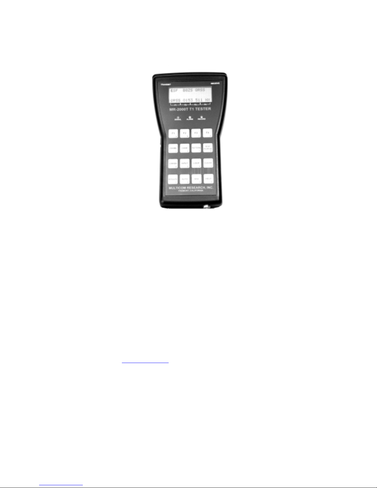
Description and Operating Manual
E1/Fractional E1 Tester
MR-2000E
E1 TESTER
For examining E1 and Fractional E1 networks.
Description and Operating Manual
Manual Revision A
Yoda Communications, Inc.
www.yoda.com.tw
Page 2

NOTE
The information in this document is subject to change without notice.
Yoda Communications, Inc. (also known as Yoda) assumes no responsibility for any damages arising from
the use or inability to use this document, including but not limited to lost revenue, lost data, claims by third
parties, or other damages.
Copyright Notice
Copyright Yoda Communications, Inc. 2000.
All rights reserved.
No part of this document may be copied, photocopied, reproduced, translated, or reduced to any electronic
medium or machine-readable form without the prior written consent of Yoda Co mmunications, In c. (Yoda).
Warning
The instrument uses the switching power supply technology. Please 'DO NOT' open th e box yourself. The
box will be opened by an authorized service department or a manufacturer only.
Warranty
This Product is warranted against defects in materials and workmanship for a period of one year from the
date of shipment. During the warranty period, Yoda will, at its option, either repair or replace products
which prove to be defective.
For warranty service or repair, this product must be returned to a service facility designated by Yoda.
Buyer shall prepay shipping charges to Yoda and Yoda shall pay shipping charges to return the product to
Buyer. However, Buyer shall pay all shipping charges, duties, and taxes for products returned to Yoda
from another country.
Limitation of warranty
The foregoing warranty shall not apply to defects resulting from improper or inadequate maintenance by
Buyer, Buyer-supplied interfacing, unauthorized modification or misuse, operation outside of the
environment specifications for the products, or improper site preparation or maintenance.
2
Page 3

CONTENTS
INTRODUCTION ……………………………………………………………………… 4
Audience …………………………………………………………………………….….. 4
Getting Started ……………………………………………………………….…………. 4
LCD Display ……………………………………………………………………………. 5
LED Indicators ………………………………………………………………………….. 5
Soft Keys …………………………………………………………………………….….. 5
Categorized Function Keys …………………………………………………………...... 6
Categorized Function Key Descriptions ………………………………………………... 6
The FRAME Key ……………………………………………………………………...… 6
The CODE Key …………………………………………………...……………………... 6
The PATTERN Key ……………………………………………………………………... 6
The TEST PERIOD Key ………………………………………………………….…….. 7
The ERROR Key ………………………………………………...…….……………….. 7
The INPUT Key .................................................................………………………….…... 7
LIU...........................................................…………………………………………….….. 7
CLOCK ..............................................................................……………………………… 8
The LOOP Key ..................................................................……………………………… 8
The AUTO Key ..................................................................……………………………… 9
The ADV. Key ...................................................................…………………..………… 10
ALARM enable/disable ......................................................…………………….……… 10
POWER conservation enable/disable .................................……………………….…… 10
Nx64 (Fractional E1)..........................................................………………………..…… 10
Additional Bits Manipulation ............................................……………………….…… 11
IDLE Code Define .............................................................………………………..…… 11
DATA Pattern Received .....................................................……………………….…… 11
SIG (Signaling Bits) ..........................................................…………………….……..… 11
CLEAR ................................................................................…………………………… 11
S/N ........................................................................................……………...…………… 11
The HELP Key .....................................................................…………………………… 11
APPENDIX A FACTORY DEFAULT SETTINGS.............……………………...…… 12
APPENDIX B ABBREVIATIONS USED ..........................…………………….…….. 13
APPENDIX C SPECIFICATIONS......................................…………………...…….… 14
3
Page 4
Introduction
Audience
The MR-2000E E1 Tester is designed for routine maintenance, installation, acceptance testing, and fault
isolation of the E1 circuits.
The tester allows for intrusive or non-intrusive testing of the E1 circuits. Bit error rate testing (BERT) can
be performed on any combinations of the DS0 channels on a contiguous, non-contiguous basis or at the full
E1 rate(2.048 Mb/s).
The specially designed function keys plus the soft keys make the test easier. The user-friendly Auto and
Help keys guide you through difficulties step by step.
This manual contains information about the Yoda E1 Tester and is intended for novice as well as expert. It
provides more graphical explanations and structured box diagrams for user to grab the design concept of
the product.
Getting Started
This chapter tells you about the basic features of the instrument and shows you the information
arrangement on the LCD display.
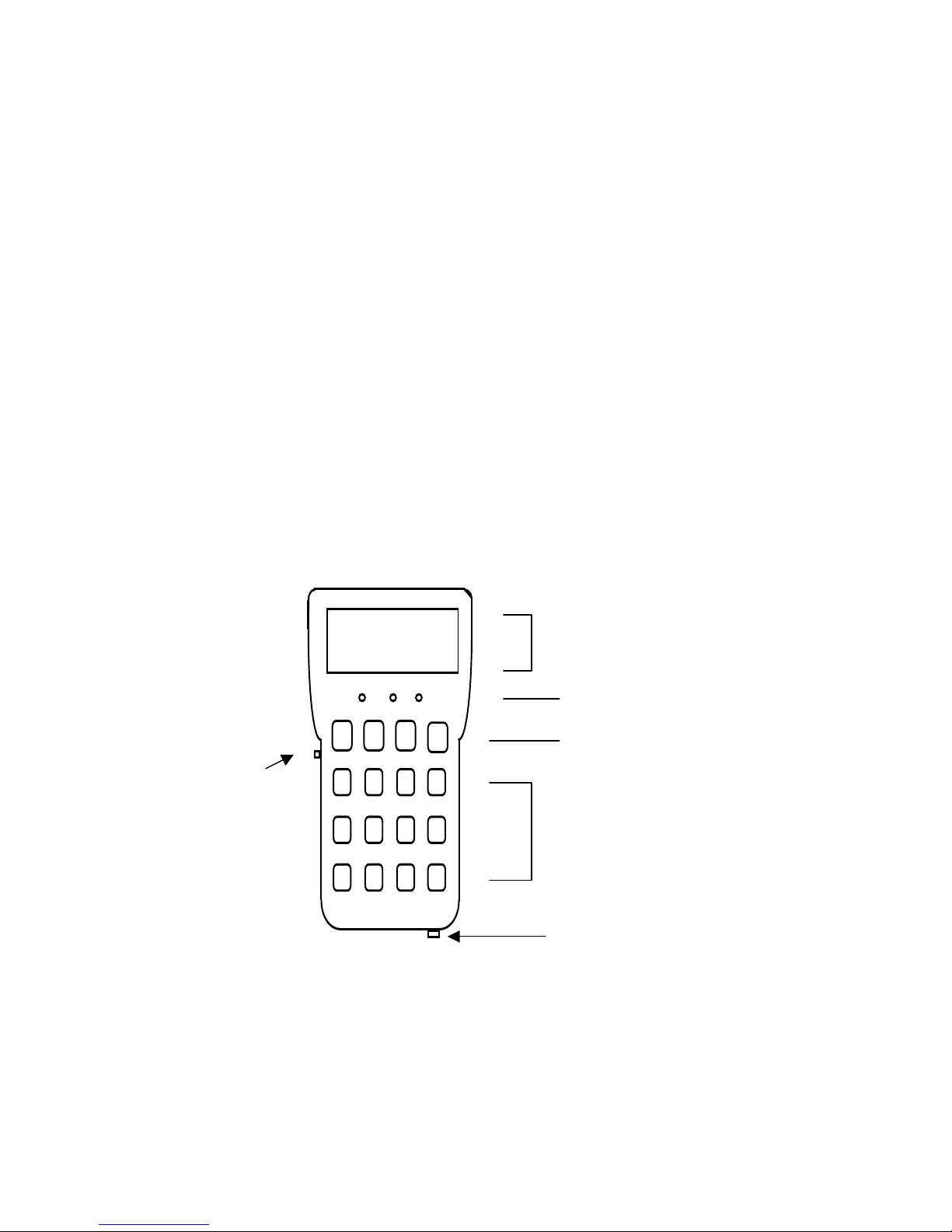
TRANSMIT RECEIVE
LCD Display
XXX YYY ZZZ WWW
LED Indicators
F1
F2
F3
Power
Switch
F4
MULTICOM RESEARCH, INC.
Soft Keys
Categorized
Function
Keys
DC 9V Power
4
Page 5

_
_
_
LCD Display
FAS HDB3 QRSS
_ __ __ __ __ __ __ __ __
_ __ __ __ __ __ __ __ __
_ __ __ __ __ __ __ __ __
QRSS O153 511 NX
F1 F2 F3 F4
The LCD Display is divided into three parts. The top line displays the E1 setups for transmitting data to
and receiving data from a remote device. The second and third lines display the information regarding
current function selection. The bottom line displays the choices within each function category. For
example, press F1 key for selecting the QRSS pattern, F2 for the O153 pattern, etc. The NX, NEXT or
MORE selection indicates more items are available when the F4 key is pressed.
LED Indicators
There are three LED indic ators wh ich are fo r signal , alarm and record. The green signal LED indicates the
existence of incoming E1 signal. If there is no incoming E1 signal, the green LED indicator will be off.
The red LED indicator shows incoming E1 sign al problems. The red LED is a real-time indicator. If there
is any incoming signal problem then the red LED indicator will be on. If the problem ceases to exist, the
red LED indicator will turn off automatically. The yellow LED records any incoming alarms during a
period of time. If the yellow LED is on then it means there was occurrence of incoming alarm. The yellow
LED indicator will not clear itself automatically until the CLEAR button is pressed or a new test has been
started.
To start a new test, such as changing the framing pattern, changing the E1 coding, changing the test pattern,
changing a new test time period or initiating an AUTO command, will clear the yellow LED indicator as
well as reset the error counters.
E1 Signal
Information
Information
Selections
Soft Keys
There are four Soft keys, F1, F2, F3, and F4, which correspond to the information displayed on the fourth
line of the LCD display. Whenever there are functions displayed on the fourth line, it means the Soft keys
are activated to be used.
5
Page 6

CATEGORIZED FUNCTION KEYS
There are twelve categorized function keys. Each categorized function key has more than one item
selections which can be chosen with the soft keys. For example, when the PATTERN function key is
pressed, a list of patterns will be displayed on line four. If there are more than four items for the
categorized function key then NX will show up above the F4 soft key. All items can be accessed through
those four soft keys.
Categorized Function Key Descriptions
The FRAME Key
To select the E1 framing format for transmission and receiving signals.
FRAME
The CODE Key
To determine whether the tester transmits with AMI-encoded data or HDB3 encoded data.
CODE AMI
HDB3
The PATTERN Key
To select the test patterns.
PATTERNS: QRSS ALL ONES
FAS
CAS
CRC4
CRC+ (CRC4+CAS)
O153 (2E20-1) All ZEROS
511 (2E9-1) ALT 1/0
2E31-1 3 in 24
2E32-1 Double ALT 1/0
2E29-1 1 in 16
2E28-1 1 in 8
2E25-1 1 in 4
2E23-1
2E22-1
2E21-1
2E18-1
2E17-1
2E15-1
2E11-1
2E10-1
2E7-1
2E6-1
2E5-1
2E4-1
2E3-1
6
Page 7

The TEST PERIOD Key
This key selects the test time frames. There are five test time frames listed as follows. At the end of the
test time frame, all alarm counters and alarm records will be frozen. The records can be displayed by
pressing the RESULT category key with the HISTORY selection.
TEST PERIOD
cont (continuous mode) ♦
♦
15 (15 minutes mode)
♦
30 (30 minutes mode)
♦
60 (60 minutes mode)
♦
12HR (12 hours mode)
The ERROR Key
This key inserts alarms and errors into the outgoing E1 data stream for testing purpose.
ERROR __________ ALARM _________ AIS
___ SAIS
___ RA
_____ ERROR __________ LOGIC
___ SINGLE
___ RATE
AIS - unframed all ones to be transmitted.
SAIS - signaling all ones
RA - Remote Alarm
Logic Single selection: generate single bit error.
Logic error rate selection: 1E-1, 1E-2, 1E-3, 1E-4, 1E-5, 1E-6 and 1E-7.
The INPUT Key
This key contains the selections for E1 signal interface set-ups.
INPUT _______ LIU ________ TERM
____ DSX
____ BRIDGE
___ CLOCK _____ LOCAL
____ REMOTE (LINE)
LIU (Line Interface Unit)
1. TERM (Default): E1 input with a 120ohm termination. The tester at this mode accepts an E1
signal attenuated between +6 dB and -43 dB due to cable loss.
2. DSX: E1 input with a 120ohm termination . A 6 dB gain is added to compensate the input signal
loss due to the loss at the DSX-Monitor ports.
3. BRIDGE: E1 input with a high impedance for use in monitoring E1 signals without altering the E1
signal.
7
Page 8

CLOCK
This item selects the clock sources which is either LOCAL (internal) or REMOTE (clock ex-traced from
line). LOCAL selection is the default.
The LOOP Key
The Loop key selects the LOOP-UP and LOOP-DOWN codes for use in various applications. The tester
can initiate a LOOP command for Full E1 or Fractional E1 based on the current settings.
(FULL E1)
LOOP ______ IN BAND ________ UP
____ LOCAL LOOP-UP
(TESTER LINE LOOP)
__ DOWN
____ LOCAL LOOP-DN
(TESTER LOOP-DOWN)
(FRACTIONAL E1)
LOOP ____ IN BAND ____ UP
__ V.54 (P-P) Activate
__ LOCAL LOOP-UP
(TESTER LINE LOOP)
__ IDLE CH LP UP
__ DOWN
__ V.54 (P-P) Deactivate
__ LOCAL LOOP-DOWN
(TESTER LOOP DOWN)
__ IDLE CH LP DN
User selects the loop code transmitted through Full E1 or partial E1 (FE1) by pressing the LOOP key and
related items.
LOCAL LOOP-UP or LOOP-DN
This selection puts the tester into Line loopback which means all the incoming E1 signal will be transmitted
back to LINE. In the mean time, the data will continue to pass through the receive side framer in the tester
as it would normally do but the data transmitted from the tester will be stopped. The alarm counters will
record if there is any error detected in the incoming data stream.
FE1 IDLE CH LP UP
(Fractional E1 IDLE Channels Loop Up)
This item can loopback IDLE channels and the DS0 channels not intended for the BERT test back to E1
Line. For Example, the PBX voice ch annels which you don’t want them to be disturbed during the BERT
test can be loopbacked (ignored). The enabled DS0 channels will be drop ped and inserted with the BERT
test pattern. To enable a DS0 channel, go to ADV.=> Nx64 => BOTH => Ch.#
FE1 IDLE CH LP DN
(Fractional E1 IDLE Channels Loop Down)
This Item Deactivates the Looped channels.
The CLEAR Key
The CLEAR key resets all counters to zero. It also clears all indicators and the history records to be ready
for a new test.
The RESULT Key
This RESULT key displays all the E1 status of the current stage, the record log of the events within the past
time frame and the error counters.
8
Page 9

RESULT _____ Current ______ E1 frequency
___ History Full or Partial E1
Alarm Log Current Alarms
___________________
A
Bit Errors
Bit Erred Second (Bit ES)
Bit Error Rate (BER)
BPV Errors
BPV Erred Second (BPV ES)
BPV Error Rate (BER)
FRAME Errors (FRM ERR)
FRAME Erred Second (FRM ES)
CRC Errors (CRC ERR)
CRC Erred Second (CRC ES)
E-bit Errors
E-bit Erred Second
End of Report
ELAPSE time
Note: If the CONT item is chosen for the TEST PERIOD key then the elapse time information in the
RESULT key display will be zero.
The AUTO Key
The AUTO key automatically detects and displays the incoming E1 signal's format, coding and pattern. It
will automatically synchronize itself. So it is the most effective way to catch the E1 line information. It
also restarts the counters and resets the alarms like the CLEAR key.
9
Page 10

The ADV. (Advanced functions) Key
This ADV. key gathers many advanced functions which may not be used in the normal operation.
ALARM ENABLE/DISABLE
The first item for this key is the alarm enable and disable. Some alarm detections are on by default. User
can change the alarm configurations during the operation.
ALARM
Initially off, under the ENABLE group __ RDMA (Receive Distant MF Alarm)
Initially on, under the DISABLE group
AIS (UNFRAMED ALL ONES) ♦
♦
SAIS (SIGNALLING ALL ONES)
♦
LOC (LOSS OF CARRIER)
♦
LOS (LOSS OF FRAME SYNC.)
♦
PLOS (PATTERN LOSS OF SYNC.)
♦
BED (BIT ERROR DETECTED)
♦
FRM (FRAME ERROR DETECTED)
♦
CRC (CRC ERROR DETECTED)
♦
BPV (BPV ERROR DETECTED)
♦
E-b (E-BIT ERROR DETECDTED)
If an alarm item is initially on under the DISABLE group then it can be disabled by the user and will
automatically be listed under the ENABLE group. The same situation applies to the initially off items.
POWER
The power selection is a toggle switch. It is initially turned on which means the tester is running under full
operations. In some cases, the analysis is the only thing needed so user can turn off the transmitter which
can conserve more than one third of the power consumption. This way, the operating time can be extended
from eight hours to twelve hours.
POWER ____ ENABLE (will enable power conservation mode which will turn off the transmitter to
save power) Or
__ DISABLE (will disable power conservation mode which will turn on the transmitter)
Nx64
Nx64 ____ TX (Define the transmitting DS0 channel)
__ RCV (Define the receiving DS0 channel)
__ BOTH (Define both directions at once)
This item changes the tester into the fraction E1 mode. It can change usable channels for TX (Transmit),
RCV (Receive) or BOTH at the same time. The display will show thirty or thirty-one dots each represents
a DS0 channel. At the bottom of the screen it will ask for channel number to input. The valid channel
number input will be from 02 to 32. The preceding 0 will be needed for single digits. After the user types
in the channel numbers, an asterisk will replace the dot at the corresponding channel position which
represents the DS0 is enabled for use in BERT test.
The DS0 channels can be contiguous or non-contiguous on Receive or Transmit or both directions.
The unused DS0 channels will be filled with the IDLE code.
10
Page 11

Additional Bits Manipulation
BIT ____ TX ____ Si
RCV __ Sa
__ Code Word (CRC-4, NFSA Bit n)
__ E-b (CRC-4, FRAME 13, 15)
__ S-b (Spare Bits, CAS MFM Bits
T/S-16, Frame-0 Bit 5,7,8)
This item changes or displays the bits’ information according to the framing selection.
By pressing the RESULT key and selecting the CURRENT item, the 'FULL E1' or 'Nx64' information will
be displayed.
IDLE
There are three choices for the IDLE item which are 7E, 7F and FF. The selected code will be inserted into
the unused channels in the Nx64 mode. The IDLE value 7E is default at power-up.
DATA
By selecting this option, the tester will capture incoming data every 32 bits received on the payload and
display on the second and the thir d lines of the screen. The order of the captured data is displayed from the
upper left to the lower right. The last bit received is the lower right bit.
SIG
The SIG (signaling bits) is embedded in the T/S 16 of the CAS data stream. There are two directions for
the SIG: TX (transmit) and RX (receive). The SIG on the TX direction can be changed by the user. In the
RX direction, user can check the incoming ABCD signaling bits information for all channels by pressing
the MORE (F4) soft key. In the TX direction, user will be asked to enter a channel number for the
signaling bits. The valid channel numbers range from 02 to 32(Except 17). Again, the preceding 0 for
single digits is needed in the channel number input. After user enters the ch annel number, the cursor will
appear at the place where user can change the information. Only 0 and 1 are allowed for the signaling bit.
At this moment, the keyboard is engaged for inputting numbers so the function key is disabled un til the
user goes through all 30 channels by pressing the MORE (F4) button.
CLEAR
By selecting this item, all Error Counters will be reset to zero and start a new test.
S/N (Serial Number)
This item will show the tester's serial number on screen for reference and maintenance.
The HELP Key
The HELP key displays helpful information relating to user's current operation.
11
Page 12

APPENDIX A
FACTORY DEFAULT SETTINGS
MODE FULL E1
FRAME FAS
CODE AMI
INPUT TERM
PATTERN QRSS
TEST PERIOD CONTINUOUS
LBO 0 dB
IDLE CODE 7E
ERRORS OFF
POWER CONSERVE MODE OFF
12
Page 13

APPENDIX B
SYNONYMS AND ABBREVIATIONS
AIS Unframed ALL ONES.
ALRM Alarm
BED Bit Error Detection; Set when bit errors are detected
FRM E1 Frame Alarm
LIU Line Interface Unit
LD Loop-down
LU Loop-up
LOC Loss of Carrier; set when 255 consecutive zeros have been detected.
LOCAL Tester
NX Next
PLOS Pattern Loss of Sync; when 6 or more bits out of 64 are received in error.
POWR Power
RDMA Receive Distant MF Alarm.
Set when bit 6 of timeslot 16 in frame 0 has been set for two consecutive multi-frames.
S/N Serial Number
SIG Signaling bits (AB or ABCD Bits)
SAIS Signaling All Ones.
13
Page 14

APPENDIX C
SPECIFICATIONS
Operating Modes
Output Frequency: 2048000b/s +/-25ppm (0 to 70C) ♦
♦
E1 Framed (FAS, CAS, CRC-4, CRC-4+CAS)
♦
Fractional E1
♦
Nx64 kb/s (N=1 to 31)
♦
Contiguous or Noncontiguous Channel Selections
♦
E1 Codes (AMI, HDB3)
♦
Signaling Bits Transmit/Receive
♦
Tester Loopback
♦
Idle Codes (7E, 7F, FF)
Receive Input
♦
Input Frequency: 2048000 b/s +/-50ppm
♦
Sensitivity: 0 to -43 dB (up to 6000ft.)
Input Impedance
♦
TERM: 120 ohms nominal
♦
DSX: 120 ohms nominal
♦
Bridge: 1000 ohms nominal
Output Specifications
♦
Line Build Out (DSX-1): 120 Ohms Line.
♦
Line Build Out (DS1): 0dB.
Meets the latest E1 specifications including ITU G.703, G.704, G .706, G.823, AND I.431 as well
as ETS 300 011, 300 166, TBR 12 and TBR 13.
Line codes
AMI and HDB3
Error Injection
Logic Errors: Single or rate
Rate: 1E-1 to 1E-7
Patterns
♦
Pseudorandom patterns:
2E3-1, 2E4-1, 2E5-1, 2E6-1, 2E7-1, 2E9-1, 2E10-1, 2E11-1(2047), 2E15-1,
2E15-1 Inverted, 2E17-1, 2E18-1, 2E20-1(O.153), 2E20-1(QRSS), 2E20-1 Inverted, 2E21-1,
2E22-1, 2E23-1(O.151), 2E23-1 Inverted, 2E25-1, 2E28-1,
2E29-1, 2E31-1, 2E32-1
♦
Repetitive patterns:
All Ones, All Zeros, Alternating Ones and Zeros, Double Alternating Ones and Zero s, 3 in 24, 1 in
16, 1 in 8, 1 in 4.
Loop Code Generation
Fractional E1 Idle Channels loop-up and loop-down.
Power
External, Input 220VAC/Output 9VDC@300MA Internal, 4AA Nickel-Metal Hydride.
14
 Loading...