

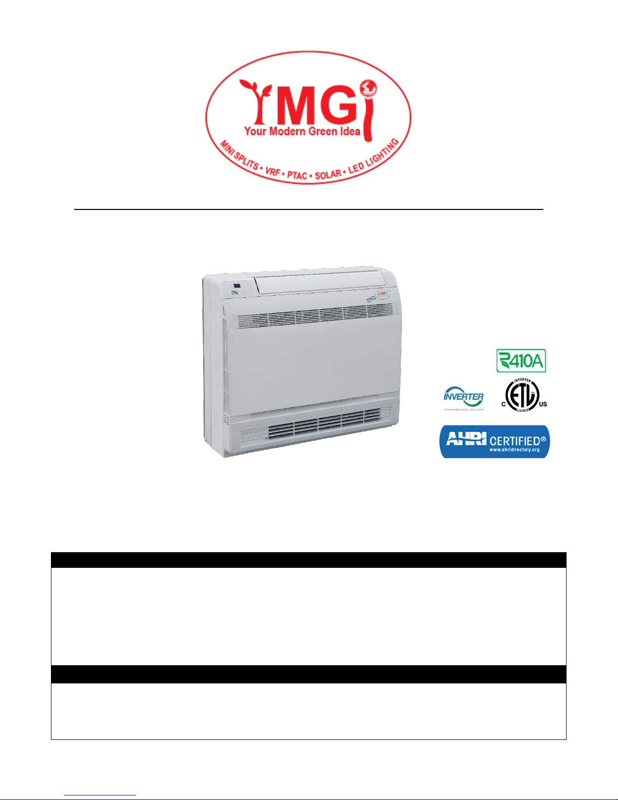
YMGI VRFI-07EL-D2B(55)5, VRFI-12EL-D2B(55)5, VRFI-09EL-D2B(55)5, VRFI-18EL-D2B(55)5 User Manual
Page 1
NOTICE
This product is designed and manufactured to be free from any defects in material and workmanship during normal use and
maintenance. Installation, operation, maintenance and repairs must follow all standards and professional practices for regular
cooling and heating equipment, such as NEC, State, or Local Codes and all related documents/manuals provided by YMGI.
Failure to follow and adhere to all codes and documentation can cause damage to equipment, property or even personal injury.
Installer: Must be currently licensed/certified HVAC technicians only. Must Read the manual and all provided documents prior
to installation. Complete and fill out all required information on the Warranty Registration Card.
User: Retain this manual and all supplied documents for your records and future reference.
Servicer: Use this manual for information concerning servicing and maintenance of this product.
SAFETY WARNING
Only qualified technicians should install and service this equipment. The installation, startup, operation and servicing of this
equipment can be hazardous and requires a HVAC professional who has been trained, licensed and certified. Installations,
adjustments or any equipment alterations done by an unqualified person could result in serious injury and even death. When
working on the equipment, observe all precautions in the provided documents, on the tags, stickers, and labels that are attached
to or placed on the equipment.
YMGI, Engineered Comfort Products for A Sustainable and Efficient Green World!
Multi Variable Air Conditioners Console Indoor Type Unit
VRFI-07EL-D2B(55)5
VRFI-09EL-D2B(55)5
VRFI-12EL-D2B(55)5
VRFI-18EL-D2B(55)5
Thank you for choosing this YMGI product. Please read the user’s manual carefully before installation/operation and retain for
your records and future reference. If you need a replacement copy, please contact your local agent or visit www.ymgigroup.com
to download a current electronic version.
1
Page 2

TABLE OF CONTENTS
Introduction .................................................................................................................................................................. 3
Note From YMGI – Must Read ................................................................................................................................... 5
Installing Technician/Contractor's Responsibilities ............................................................................................................. 7
Limited Product Warranty ............................................................................................................................................ 8
Limited Product Warranty Registration Card ............................................................................................................... 9
Why Does YMGI Group Require Installation and Service to Be Performed
100% By Currently Licensed or Certified HVAC Technicians/Contractors ................................................................ 10
Suggestions to Aid You in Hiring an HVAC Contractor ............................................................................................. 10
Safety Precautions ..................................................................................................................................................... 11
Installation of Indoor Unit ........................................................................................................................................... 12
Component Identification ........................................................................................................................................... 22
Working Temperature Range .................................................................................................................................... 23
Remote Controler ....................................................................................................................................................... 24
Maintenance Method ................................................................................................................................................. 28
Function Description .................................................................................................................................................. 33
Anylizing Malfunction .................................................................................................................................................. 33
Recommended Tools for Installation ......................................................................................................................... 34
User Notes and Installation/Service/Maintenance Notes ........................................................................................... 35
2
Page 3

Introduction
Indicates a potentially hazardous situation which, if not avoided, could result in serious
injury or even death.
Indicates a potentially hazardous situation which, if not avoided, could result in minor or
moderate injury. It is also used to alert against unsafe practices.
Indicates a situation that could result in equipment or property-damage only. It can also
be used to call attention to important details within this manual.
Read this manual carefully, making sure you understand all the instructions, practices and procedures contained in this manual.
Be sure you are familiar with all the safety advisories that appear throughout this manual. Your personal safety depends upon
your observance of all precautions contained in this manual.
The 3 types of advisories are defined in the following table:
Important Environmental Concerns
Studies have shown that certain man-made chemicals can affect the earth’s stratospheric ozone layer when released into the
atmosphere. Refrigerants that contain Chlorine, Fluorine and Carbon (CFCs) and those containing Hydrogen, Chlorine, Fluorine
and Carbon (HCFCs), may affect the ozone layer. Not all refrigerants have the same potential impact on the environment. YMGI
Group advocates for the responsible handling of all refrigerants including industry replacements for CFCs such as HCFCs and
HFCs.
Responsible Refrigerant Practices
YMGI Group believes that responsible refrigerant practices are important to our customers, the HVAC/R industry and the
environment. All HVAC/R technicians who handle refrigerants must be certified. The Federal Clean Air Act (Section 608) sets forth
the requirements for handling, reclaiming, recovering and recycling of certain refrigerants, the equipment and tools necessary to
perform these service procedures. In addition, some states or municipalities may have additional requirements that must also be
adhered to for responsible management of refrigerants. HVAC/R technicians must know the applicable laws and follow them.
Disposal Notice
Do not dispose of this product or its components as unsorted municipal waste, as they contain items that may require special
treatment. Contact your local waste management company for details.
Proper Field Wiring and Grounding Required!
Failure to follow established electrical codes can result in death, serious personal injury and property damage. All field wiring
MUST be performed by qualified personnel, such as a currently licensed electrician. Improperly installed and grounded field wiring
poses FIRE and ELECTROCUTION hazards. To avoid these hazards, you MUST follow the requirements for field wiring
installation and grounding as described in this manual, by NEC and your state/local electrical codes.
Personal Protective Equipment (PPE) Required!
Failure to wear proper PPE for the job being undertaken could result in serious injury or even death. Technicians must take the
necessary precautions to protect themselves from potential electrical, mechanical, and chemical hazards and MUST follow all
precautions in this manual and on the tags, stickers, and labels, as well as the instructions below:
• Before installing or servicing this unit, technicians MUST put on all PPE recommended for the work being undertaken.
ALWAYS refer to appropriate Material Safety Data Sheets (MSDS) and Occupational Safety and Health Administration
(OSHA) guidelines for proper PPE.
• When working with or around hazardous chemicals, ALWAYS refer to the appropriate MSDS sheets and OSHA guidelines
for information on allowable personal exposure levels, proper respiratory protection, and handling recommendations.
If there is a risk of arc or flash, technicians MUST put on all PPE in accordance with NFPA 70E or other country-specific
requirements for arc flash protection, PRIOR to servicing the unit.
Copyright
This document and the information contained therein are the sole property of YMGI Group and shall not be used or
reproduced in whole or in part, without the written permission of YMGI Group. YMGI Group reserves the right to
revise this manual at any time and to make changes to its content without obligation to notify anyone about any
modifications, revisions or changes.
3
Page 4
Instructions for installation and use of this product are provided by the manufacturer.
Installation must be performed by authorized and licensed personnel only and in accordance with all the
requirements of this manual, the NEC, CEC and any state/local codes.
For safe operation of this unit, please read and follow all instructions carefully.
The total operation capacity of the indoor units should not exceed 120% of the total capacity of the outdoor units
if all indoor units must operate at their peak capacities all the time. Otherwise, the heating and cooling operation
will be diminished and less efficient which could damage the units.
Any person responsible for system operation or system maintenance should retain this manual for reference.
If the unit fails to operate normally, please contact your authorized system installer or HVAC professional as soon
as possible and provide the following information:
• Data on the unit (model number, serial number and owner’s name).
• A detailed description of the unit’s problem before and after the problem occurred.
To avoid personal injury or property damage, do not disassemble the unit yourself. If disassembly is required to
check the unit, contact your authorized system installer or HVAC professional as they have the experience and
training necessary to perform this task.
Note: Each unit has been thoroughly tested to ensure it operates correctly before leaving the factory.
Basic Cautions and Warnings
All units shall be installed by an experienced HVAC licensed contractor or technician. Read all manuals before
installation, startup and operation.
All NEC, state, local codes and installation instructions must be followed for all units, otherwise, the unit warranty
will be void and could result in serious damage to people or property.
YMGI Group is not responsible for any damage or loss due to Do-It-Yourself(DIY), self-installation or any improper
installation, operation, service or natural disasters of any kind.
Do not connect power to the unit until all wiring, tubing and all unit inspections and tests have been completed.
Ground the unit according to the instructions and adhering to NEC, state and local codes.
All wiring connections must be correct and secure. Loose wire(s) or improper contacts may cause arcs or
overheating which can result in a fire hazard.
4
Page 5
Note From YMGI – Must Read
Dear Customers, Installers, and Contractors
Thank you for choosing a YMGI product.
All YMGI's products are fully tested and have passed rigorous safety, performance and manufacturing standards
before being packed and shipped. YMGI only uses suppliers that meet our strict standards for high quality and
performance for all parts. YMGI also recognizes a quality installation is equally important therefore your system
must be installed by a licensed HVAC professional. A quality installation ensures your unit will operate at its highest
efficiency and peak performance for many years of worry free comfort; while a poor installation can result in unit
failure and cause the unit to operate inefficiently, either immediately or over time, resulting in costly repairs.
Because a quality installation is so critical, YMGI provides detailed information in our manuals which will aid the
installing technician and the owner of the unit(s).
The YMGI equipment you purchased is either a split-type or a self-contained cooling/heating system. These types of
systems require a certified and licensed HVAC professional technician for proper installation. Only a certified and
licensed HVAC professional technician will have the knowledge, experience, and attention for all required details to
perform a complete and successful installation. This equipment is different from a window or portable type air
conditioners you can purchase from local big box and retail stores which the manufacturer may not require certified
and licensed personnel to install.
Reading and following YMGI Group recommendations and requirements contained in the following pages and other
documents, is the first step to help ensure a smooth installation and proper operation of your unit for many years.
YMGI does not recommend nor allow any Do-It-Yourself (DIY) installation (partially or fully). Due to the complexity
of the installation of this product most DIY installations usually have problems, either immediate or in the near
future. These problems can cost more to fix than any upfront savings. YMGI warranty does not cover any DIY
units.
If you have any questions about your unit or if the unit has a problem, you should first check the manual. If you
can’t find a solution, then contact your local installer or service technician to schedule a service appointment. The
technician can physically inspect the unit. If at the time of inspection, the installer or service technician has any
questions about the unit, they can contact YMGI technical support division directly at:
Toll Free Number: (866)833-3138 or Email: [email protected]
IMPORTANT: YMGI Group is the MEDIA AUTHORITY:
YMGI Group, located in O'Fallon, MO 63366 is the author of all media produced for its products and is the only party
able to give any additional explanation for any data, definitions and or descriptions found within any of its media,
including but not limited to YMGI product brochures, manuals, pamphlets, catalogs, and videos. YMGI's distributors,
installers, dealers, agents, customers or any other third parties will not supersede YMGI in anyway concerning YMGIpublished materials and their meaning. Any concerns or questions arising from YMGI distributors, installers, dealers,
agents, customers or any other third parties, should be presented directly to YMGI. YMGI will respond to any concerns
or questions, if necessary, about any of its media in writing.
5
Page 6
Be sure to only hire a certified and currently licensed HVAC Company to complete 100% of the installation so
that all details of the installation are performed correctly and completely.
Factory Warranty will be void if any portion of the installation is not performed by a licensed HVAC
contractor/technician. DIY or partial DIY will also void ALL factory warranties.
Hiring an HVAC technician that is offering their services as a "side job" rather than a licensed HVAC company
may pose possible risk. This may result in an incomplete or unsatisfactory installation, no guarantee for
workmanship, maintenance or further service to your unit.
Have the installation technician read in full the installation manual and all supplied documents for the product
model you purchased. Details within the provided documentation contributes greatly to the success and quality
of the installation. Experience with other manufacturers may not be applied fully to another manufacturer,
although there will be similarities there will also be differences. Ignoring the provided installation procedures is
an act of negligence and may cause unit failure or damage which could be permanent.
It is possible for a licensed contractor/technician to make a mistake during the installation. YMGI does not
supervise nor is able to control the contractor/technician’s installation. It is critical that the installer take each
variable into account during the initial installation. This will ensure a complete and professional
installation and that all units work properly.
The following will damage the unit and its key components resulting in loss of factory warranty:
1. Any foreign substances introduced into the system because of failure to seal the ends of the refrigeration piping
before pulling the piping through any structures at time of installation.
2. Not installing an oil P-trap in the copper suction line where the indoor unit is located 18 feet or more below the
outdoor unit.
3. Cross piping and/or cross wiring of any units including more than one single zone or a multi zone system.
4. Not conducting a positive leak check by charging the system with dry-nitrogen and performing soap bubble
testing.
5. Not conducting a negative leak check by evacuating the copper lines for 30 minutes. The vacuum must be held
at 500 microns or better for at least 5 minutes, starting a 5-minute timer after the vacuum pump is turned off.
6. Not conducting a positive leak check prior to the negative leak check.
7. Not selecting the correct size wire or circuit breaker.
8. Not answering ALL questions in the technician's checklist located inside the warranty registration form.
The following may be overlooked, ignored, or considered unimportant during your installer's installation, but
will cause your unit to underperform and may cause unit failure.
1. Any kinks in or improper bending of the copper piping.
2. Any poorly formed flares, not centering the flare with the flare nut, or not tightening all connections.
3. Not trial testing each indoor unit individually.
4. Not reading technical data (temp/time/pressure/current) after the system is stabilized (normally the compressor
needs to run at least 10 minutes before reading the data). If the data is read too early, it may lead to inaccurate
assessments about the unit.
In an effort to help protect our customers from possible faulty installations that can lead to premature unit failure,
YMGI provides the above information for you (the owner) and the technician. You can observe while your system is
being installed, even though your observation is not a guarantee your system is being or has been installed properly
and professionally. With the information provided above, you will know some things to look for and questions you can
ask. If at any time you feel there may be an issue with the installation, please have your technician contact YMGI at
(866)833-3138 x 703 with any questions, issues or concerns you may have.
6
Page 7

INSTALLING TECHNICIAN/CONTRACTOR'S RESPONSIBILITIES
1. Discuss with the customer detailed information about the structure to be conditioned, local weather (typical design, extreme
temperature/humidity conditions, cooling and heating hours), previous and existing HVAC equipment (if any), usage and dependence
on new HVAC equipment or YMGI products.
2. Performing a cooling/heating load calculation by using commercially available professional programs/methods such as Right-J
(Manual J) for residential HVAC applications and Right-CommLoad (ASHRAE RTS/CLTD) for light commercial and commercial
HVAC applications.
3. Contact your YMGI distributor/sales department or contact YMGI directly to obtain additional information to fully understand your
YMGI products, including but not limited to product features, cooling/heating performance at standard ratings/conditions and extreme
conditions, allowed indoor and outdoor temperature and humidity ranges, installation, operation, maintenance, service, warranty,
parts and any other issues pertaining to YMGI products.
4. Select the correct (most suitable) YMGI product unit models and accessories necessary for your HVAC applications and list them in
the proposal/quote, in writing, on company's quotation form or letter head, based upon the information you collected from 1, 2 and 3
listed above.
5. List your currently valid HVAC license number and EPA number in your proposal/quote.
6. Make sure you are the only party to perform the entire installation and you will not sub-contract any part of the installation to any non-
licensed parties or persons. You will be solely responsible for the entire installation that you have been contracted.
7. Make sure you have all the materials you need to properly, completely and correctly finish the installation. The YMGI units and
accessories may be just a portion of what you will need for the project. When support issues arise, remember YMGI employees and
YMGI distributors/sales, dealers and agents are not installers and may only provide suggestions. You are the only one qualified to
determine what other materials you need to complete the installation.
8. When connecting electrical wires, follow all NEC, state and local codes and ensure the installation of all YMGI units and accessories
meet these requirements.
9. Connect the unit to a correctly sized electrical power source. If the unit is installed in an area where lightning or storms occur
frequently, a correctly sized and type of power surge protector must be installed between the outdoor unit and the power source.
10. Select the correct types and sizes of HVAC circuit breakers, disconnect switch boxes, wires and conduit from circuit breaker to
disconnect box and then from disconnect box to outdoor unit.
11. Select the proper location for installing indoor units and outdoor units with all factory requirements being followed (cooling/heating
air inlets and outlets are not blocked, or restricted, mounting structure is secure, installation for convenience is considered, allow
adequate clearance for maintenance/service and all applicable codes are met).
12. Cap/tape the two ends of every copper line before running them through any structure to keep any foreign substances from entering
the copper line causing contamination. Label the copper lines A-A, B-B, C-C, D-D, or any other identifying marks on each pair of
copper lines and wiring cable sets to keep from cross-piping or cross-wiring in multiple zone installations or where pipes for different
single zone systems are close to one another.
13. Secure the wiring cables that connect between the indoor unit and outdoor unit, following all applicable NEC, state and local codes
for your installation. If there are no special NEC, state or local codes to govern how these wires are to be installed, you can tape/cable
tie them along with insulated copper line.
14. Tighten all pipe and wire connections ensuring there is no leakage or false/loose connections.
15. Conduct a positive pressure leakage test, checking each of the inter-connecting copper lines between each indoor unit and outdoor
unit by charging with dry-nitrogen at the outdoor unit’s service port (NOTE: do not back-seat stopping valve). A liquid soap solution
shall be applied at all pipe connections to check for leakage. A 1/4” - 5/16” hose/valve adaptor may be needed if you have a 1/4”
traditional manifold hose connection.
16. If there is no positive leaking, then conduct a negative pressure leakage test, checking all inter-connecting copper lines between
each indoor unit and outdoor unit by pulling vacuum at the outdoor unit’s service port (NOTE: do not back-seat stopping valve)
and checking that a vacuum level of 500 Microns can be held for at least 20 minutes.
17. If there is no leakage found at any of the refrigeration pipe connections, flip up the indoor unit’s face panel and remove its filter,
carefully pour some clear water onto the up-right aluminum coil surface to test if the water can drain freely out of each of the indoor
unit’s without finding any leakage.
18. If there is water leakage found, locate the source of the leak and correct it. Only after everything is clear and all the necessary
inspections made, engage the correct electrical power to the system.
19. Then back-seat stopping valves of the outdoor unit to release refrigerant from the outdoor unit into the inter-connecting pipes and
the indoor unit.
20. Make sure both the indoor unit and outdoor unit are powered on correctly, operating the indoor unit in fan mode first. Then move on
to test cooling, dehumidifying/drying, heating and other modes.
21. Read refrigerant pressures and pipe/valve temperatures only after the system is stabilized (normally 10 minutes after cooling/heating
mode is started successfully). Record this data into the technician checklist in the lower half section of the Limited Product Warranty
Registration Card/Form.
22. Adjust refrigerant charging level (remove refrigerant if pipe is shorter, the temperature is colder; add refrigerant if pipe is longer the
temperature is warmer), following the manufacturer's instructions. If the average pipe length is shorter or longer than 25' and
pressure/temperature readings at the outdoor unit service valves are not falling into normal ranges.
23. Explain to the user/owner about proper unit operation and maintenance. Leave your contact information to allow them to reach you.
If the customer finds the unit does not work properly and cannot resolve the issue themselves, check the customer's
units/parts/accessories and correct the issue if there is one. Communicate with YMGI-technical support line at (866)833-3138 x 703,
if further help is necessary.
Following these requirements will aid in ensuring that the units to be installed meet general HVAC practicing standards and necessary
factory requirements. Finding any possible problems early and preventing any further damage to the unit will help to ensure a properly
working unit for many years.
7
Page 8

LIMITED PRODUCT WARRANTY
Once the installation and successful testing of the system has been completely performed by a qualified
licensed/certified HVAC technician/contractor, the registration card/form is filled out completely and correctly, mailed
and filed along with a valid installation invoice from the contractor within 7 days of the original installation, the following
standard Limited Product Warranty is qualified: 10-years on the compressor and 5-year on PARTS ONLY. There
is no labor coverage.
YMGI products are designed and manufactured free from defects in workmanship, and materials for normal use.
However, if for any reason, including occasionally transporting between YMGI factories/warehouses and your delivery
location, you discover the unit has issues, YMGI Group will help field a solution by following YMGI’s established
warranty procedures:
Compressor: YMGI will warrant the compressor of a YMGI-validated and approved warranty filing, for a period of 10
years from the date of successful installation at its original installation location.
Parts: YMGI will warrant parts of a YMGI-validated and approved warranty filing, for 5 years from the date of
successful installation at original installation location. All warranty compressors and parts replaced will become the
sole property of YMGI Group and must be returned upon request. Warranty parts may be new or refurbished. All
parts are tested and approved before shipping.
At no time does YMGI Group warrant labor cost of any type. Warranty will start from the date of a successful
installation at the original installation location, or 90 days as of original shipping date from YMGI Group,
whichever comes first.
This is a standard limited liability warranty and DOES NOT cover the following:
Any damage or repairs to properties, or persons as an incident of or consequence of improper faulty
transportation, installation, operation, maintenance or service.
Any damage caused by frozen or broken water hoses or refrigeration pipes in the event of equipment failure.
Any damage due to floods, fire, wind, lightening, accidents, corrosive atmosphere.
Any damage due to interruption or inadequate electrical service to equipment.
Any products that are installed outside the US or Canada.
Any unit that has been moved from its original installation address.
Any labor costs associated with the installation or service of the unit.
Poor unit performance due to improper unit selection (SEER, Unit size).
To validate the above warranties, ALL of the following conditions must all be fulfilled:
1. The unit was fully (100%) and successfully installed by a licensed or certified HVAC technician.
2. The unit was installed following all NEC, state and local codes.
3. The unit was installed following all the information within the Instructions and User Manuals provided by YMGI
Group.
4. ALL fields, especially the technician-checklist, of the Limited Warranty Registration Card/Form were filled out
completely by the installing technician and signed by both the installing company’s technician and the unit
owner.
5. The Limited Warranty Registration Card/Form and a copy of the original installing company's invoice have been
received by YMGI Group-Warranty Dept., POB 1559, O'Fallon, MO 63366, within 7 days of successful installation.
No warranty filing will be validated or approved, if any one of the above conditions are not met.
Product registration does not guarantee the validity of this limited warranty statement.
8
Page 9
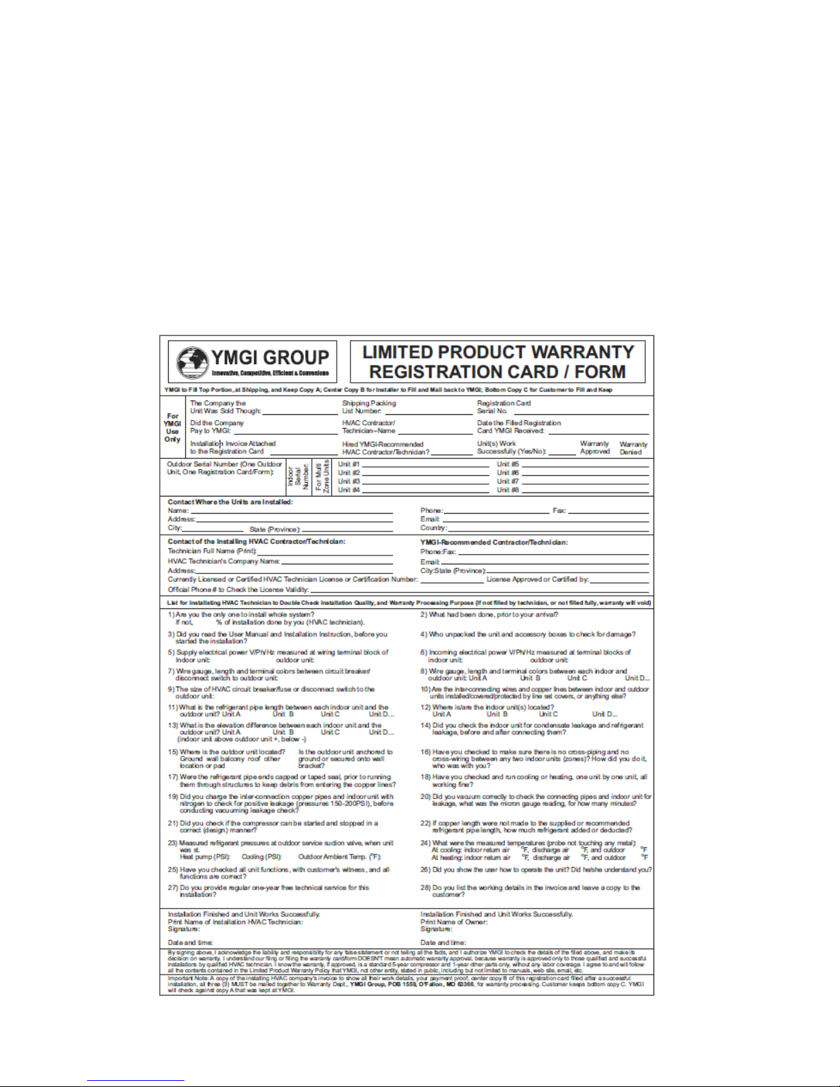
Steps to follow for warranty part replacement:
1. The installing or service technician must contact YMGI tech support at 1-866-833-3138 ext. 703 from the installation
location to check and confirm with YMGI Technical support the exact part(s) needed to fix the problem(s).
2. YMGI will check the customer's warranty filing. There will be no charge for Parts with a validated and approved
warranty. Any Parts needed for warranties that have not been validated and approved or have an invalid warranty
filing (resulting in an unapproved warranty request), will be charged accordingly.
3. YMGI will ground ship the parts ASAP. Expedited shipping is available at the customer's expense.
4. Replacement parts that have an approved warranty registration are to be warranted for the remainder of the 5-
year on parts and a 10-year compressor warranty. Purchasing of replacement parts without a valid warranty filing
or unapproved warranty request, will be sold as is and are not covered by any warranty.
YMGI is continually improving products with various engineering changes and these changes are made without
prior notice. Such improvements or changes include but are not limited to product specification, appearance,
functionality, size, packaging, etc. These improvements or changes will not void the limited warranty stated herein.
YMGI is the final authority concerning this warranty policy.
9
Page 10

WHY DOES YMGI GROUP REQUIRE INSTALLATION AND SERVICE TO BE PERFORMED
100% BY CURRENTLY LICENSED OR CERTIFIED HVAC TECHNICIANS/CONTRACTORS?
1. Expertise and Safety:
They have the training and experience to accurately and safely install and service your equipment. The equipment
runs with high-pressure refrigerant, oil and electrical current. The copper lines must be installed properly to prevent
leakage and foreign substances from contaminating the refrigerant system.
2. You will save money in the long run:
If any problem occurs with the unit that has been fully installed by a currently licensed or certified
technician/contractor, contact the original licensed or certified HVAC technician to evaluate the unit as they have
the training and experience to correct the problem quickly and efficiently. A technician may be unwilling to repair
an issue on a unit that they did not install. If you do find a technician willing to perform this service, there is an
increased possibility of higher service fees, increased service visits, or delayed service from that technician.
3. It's the law!
The federal, state and/or local government and authorities have various governing laws or regulations, guidelines,
ordinances, etc. These laws may require only licensed or certified professionals can install and service this type
of high pressure HVAC equipment.
SUGGESTIONS TO AID YOU IN HIRING AN HVAC CONTRACTOR:
1. Hire a currently practicing, licensed/certified HVAC professional technician/contractor. Technicians, who are no
longer practicing (retired, etc.) in this field, may not have current technical knowledge or may lack experience on
the equipment you have purchased.
2. Hiring a licensed technician to install your unit as a "side job" rather than a licensed HVAC company may pose
possible risk. This may result in an incomplete or unsatisfactory installation, no guarantee for workmanship and
lack of maintenance and further service to your unit.
3. Hire a technician/contractor who services customers in your local area and one you are familiar with. Local
contractors have a faster response time and it will be easier for you to determine if they are reputable.
4. Use only a reputable licensed/certified HVAC installation professional to prevent any unexpected charges due tof
unethical business practices.
5. Check their references, verify they provide professional service for their customers. N.A.T.E or A.C.C.A certified
technicians are strongly recommended.
6. Some contractors/technicians may not feel comfortable about installing equipment that has been purchased by
someone other than themselves. You can contact YMGI directly to check and see if there are contractors in your
area who have installed our products or any similar products.
7. Ask for a detailed quote for the complete installation project. A flat rate quote is the safest contract for both you
and the contractor.
8. Local HVAC technicians may charge you on a project basis or on an hourly basis. It has been our general
experience; a full single head installation normally can cost $800 to $1500. These costs are estimates, and
your actual costs may differ due to your specific job requirements and installation location.
9. Number of hours can vary depending upon each individual situation, some factors are, but not limited to:
Difficulty or complexity of securely installing the indoor unit.
Difficulty or length of the inter-connecting pipes and wires to be installed.
10. A successful installation is dependent on all these suggestions and necessary steps are followed.
11. If the contractor(s)/technician(s) are experienced with the systems/brands you purchased. You might save on
the installation cost but remember to always ask for and verify references.
12. The contracts should list and detail all work to be performed and the standards they will follow. Some contractors
are willing to include a 1-year installation/service warranty at no extra charge. Check to see if this is an available
option. If available, make sure it is included in the contract.
13. Verify and confirm the installation is completed and all the unit functions have been tested and working properly.
All items on the checklist should be checked and clearly marked in the warranty registration card/form, prior to
paying the contractor in full.
The cost of not having your unit professionally installed can be more expensive than the additional cost of hiring a
certified contractor. Protect your investment and warranty eligibility by doing it right the first time.
10
Page 11

Safety Precautions
1. Follow these instructions to complete the necessary installation process. Carefully read this manual before
installation and unit startup or servicing.
2. Wire size of power cord should be properly sized to meet the required electrical loads. Should the power cord
get damaged, the power cord should be replaced with a manufacturer approved cable.
3. After connecting the power cord, attach the electric box cover and secure properly.
4. Always meet the nitrogen charge requirements when welding pipes.
5. Never short-circuit or cancel the pressure switch as this will result in damage to the unit.
6. Connect the wired controller before energizing, otherwise the wired controller cannot be used.
7. Before using the unit, verify the piping and wiring are correct. This will avoid water leakage, refrigerant leakage,
electric shock, fire, etc.
8. Do not insert fingers or objects into the air outlet or inlet grille.
9. Open a door or window for ventilation for allowing fresh air to enter the room to avoid depleting the oxygen while
gas/oil supplied heating equipment is used during the installation.
10. Never start up or shut off the unit by means of directly plugging into or unplugging the power cord from the power
outlet.
11. Turn off the unit after it runs at least five minutes, otherwise it will influence the oil return of the compressor.
12. Do not allow children to operate this unit.
13. Do not operate this unit with wet hands.
14. Turn off the unit or disconnect the power supply before cleaning the unit. This will avoid possible electric shock
or personnel injury.
15. Never spray or splash water towards the unit. This can cause a malfunction in the unit or can result in electric
shock.
16. Do not expose the unit to moist or corrosive environments.
17. While operating in cooling mode, do not set the indoor units room temperature too low. keeping the temperature
difference between indoor and outdoor unit within 41℉ (5℃).
18. YMGI Group recommends that only properly trained and authorized personnel be allowed to repair or service
the unit. Improper repairs or servicing can result in electric shock or fire hazards. Please contact YMGI Group if
you need help locating a qualified repair or service technician.
19. Before installation, check the power supply to ensure it is sufficient to meet and is in accordance with the
requirements specified on the nameplate of the unit. Ensure the power overload is functioning correctly and
make sure it is properly maintained.
20. Installation must be performed only by an authorized installer or HVAC professional in accordance with the
requirements set by the NEC and CEC. Do not attempt to install the unit yourself. Improper handling may result
in water leakage, electric shock, fire, and voiding of the warranty.
21. Be sure to use only approved accessories and parts to prevent water leakage, electric shock and fire.
22. Make sure the unit is grounded properly prior to connecting to power source, to avoid electric shock. Do not
connect the ground wire to a gas pipe, water pipe, lightning rod or telephone line.
23. Energize the unit for 8 hours before operation. Turn off or disconnect the power within 24 hours to prevent short-
cycling (to protect the compressor).
24. If refrigerant leakage happens in a confined space during installation, ventilate immediately. Poisonous gases
can occur if the refrigerant gas is exposed to fire.
25. Volatile liquids, (such as paint thinners or solvents) if exposed to the unit’s surface will damage to the surface
finish. Only use a soft cloth along with a mild non-abrasive detergent to clean the outer casing of the unit.
26. If the unit does not operate normally or if you notice any type of burning odor, power off the unit and turn off the
main power supply, then immediately contact your YMGI authorized repair service center or HVAC professional.
11
Page 12
Installation of the Indoor Unit
Selection of The Installation Location
Select a location where cool air can be distributed throughout the room.
Select a location where condensation water can be easily drained.
Select a location on the wall or floor that can support the weight of the indoor unit.
Select a location which will allow for easy access when maintenance is required.
This appliance must not be installed in the laundry or anywhere it
can be exposed to excessive moisture.
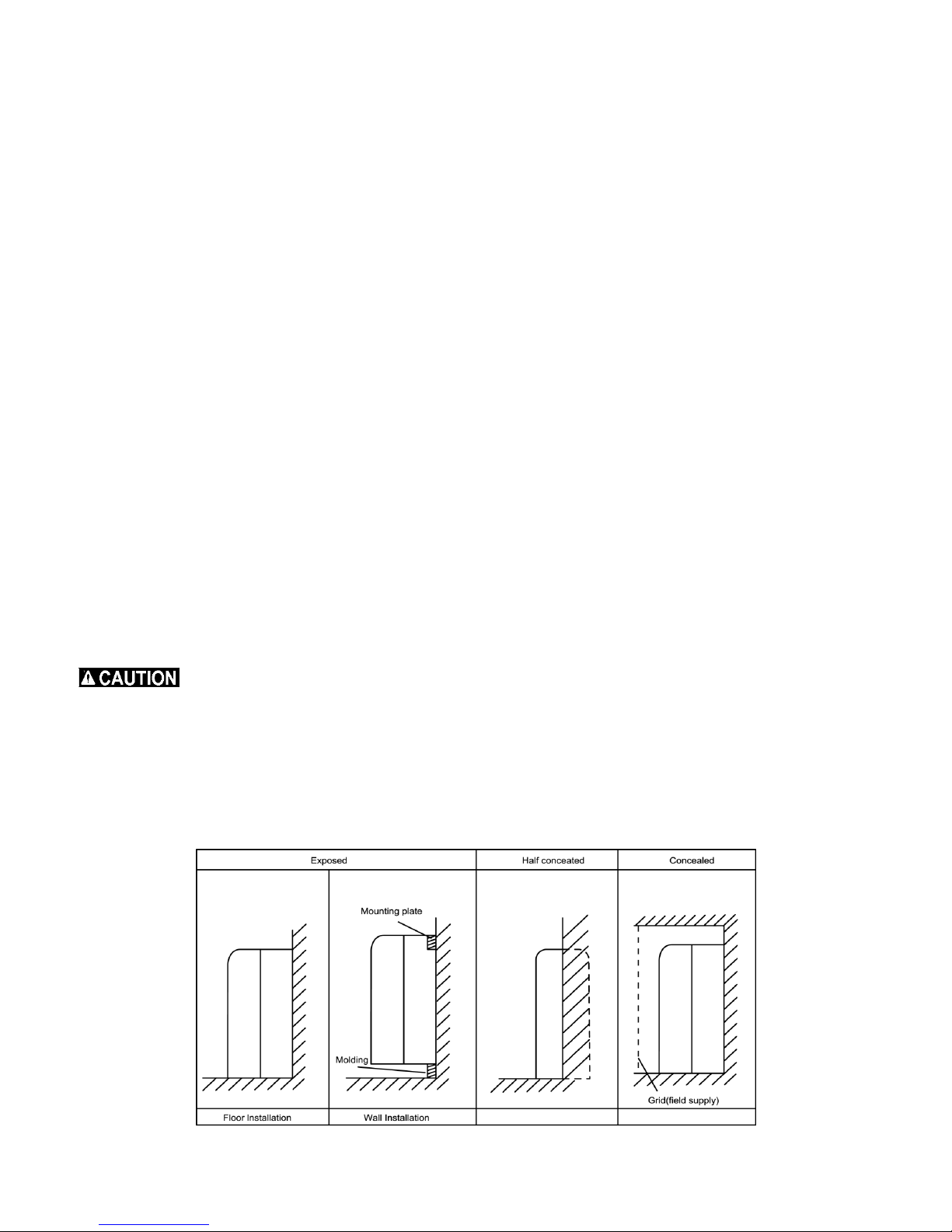
There are 2 Types of Installation
Wall mounted
Floor mounted
Indoor Unit
Locate the indoor unit in a place where:
All the specifications listed in this manual and on the indoor unit installation drawings are met.
Both the air intake and exhaust have clear paths.
The unit will not be exposed to direct sunlight.
The unit is located away from an additional heat source.
There is no machine oil vapor.
Cool/Warm air can be circulated throughout the room.
The unit is located away from fluorescent lamps manufactured with an electronic ignition, this includes both
inverter or rapid start types. Locations close to these types of lamps may shorten the range of the remote
controller.
The unit is at least 39.4 inches or 1 meter away from any television or radio otherwise the unit may cause
interference with the picture or sound.
Do not install the indoor unit where there is excessive oil in the area.
Do not install the indoor unit where there is acid in the environment.
Do not install the indoor unit where there is irregular electrical power supply.
Indoor Unit Installation Drawings
The indoor unit may be mounted in any of the three types shown here.
12
Page 13
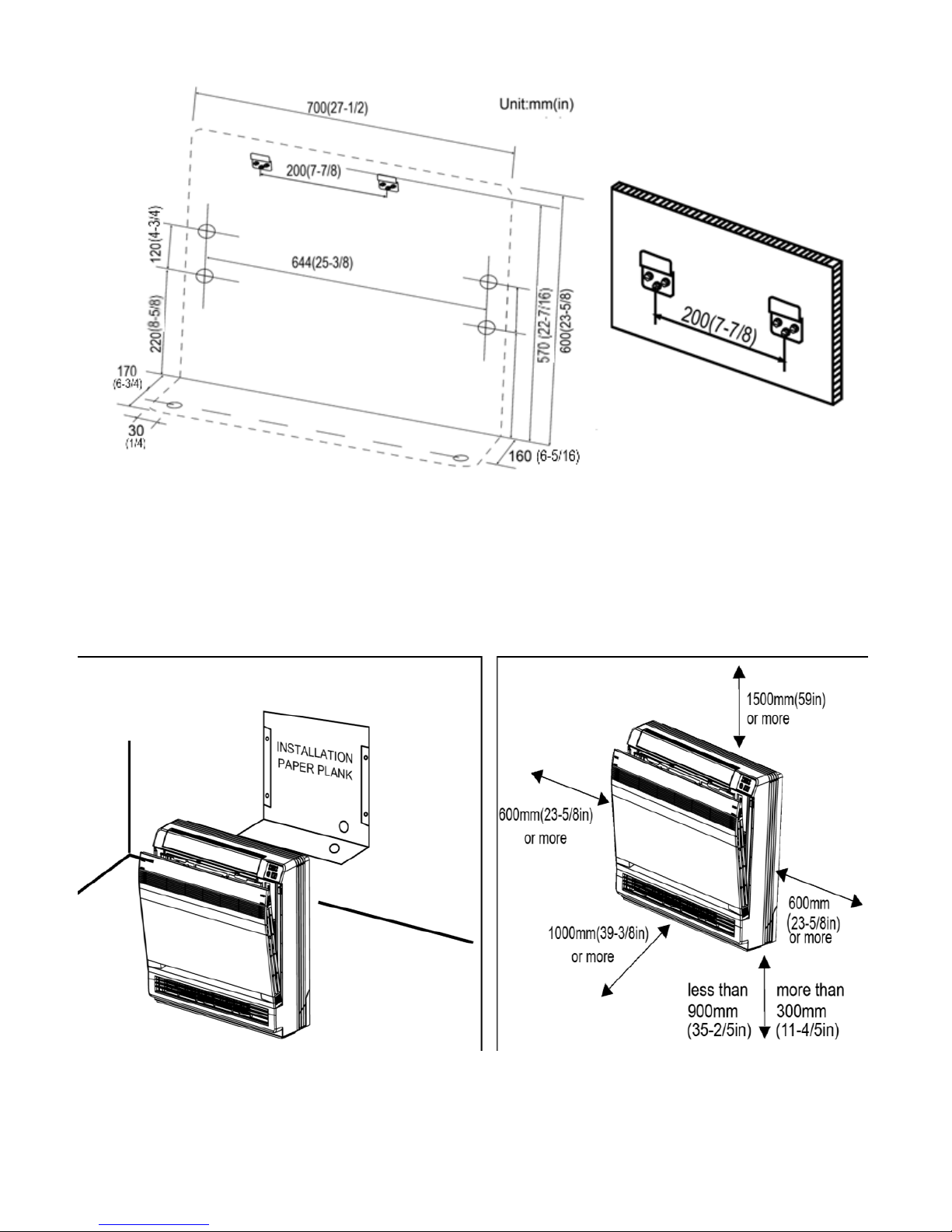
Location for securing the installation pane. Schematic drawing of hooks.
13
Page 14
Refrigerant Piping
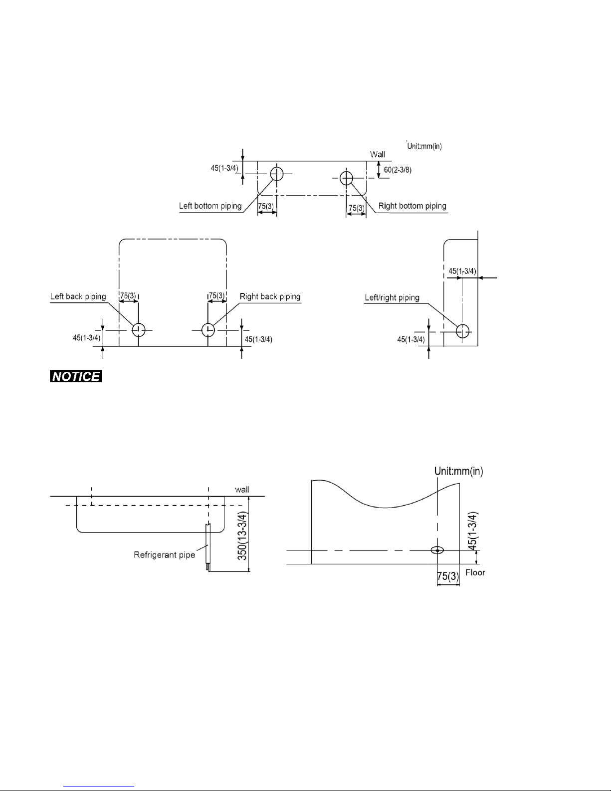
Drill a hole (65mm or 2-9/16 inches in diameter) in the spot indicated in the illustration below.
The location of the hole is different depending on which side of the unit the pipe is taken out.
For piping, see connecting the refrigerant pipe.
Allow adequate space around the pipe of the indoor unit for easier connection.
The suggested shortest pipe length is 2.5m or 98 5/16 inches. This is to avoid noise and vibration from the outdoor
unit.
Mechanical noise and vibration may occur depending on how the unit is installed and the environment in which it is
used.
Boring A Wall Hole and Installing the Wall Embedded Pipe
For walls containing metal studs or metal wall, be sure to use a wall embedded pipe and wall cover in the feedthrough hole.
Be sure to seal all the gaps around the pipes with caulking material to prevent water leakage.
Bore a feed-through hole of (65mm or 2-9/16 inches in diameter) in the wall in such a manner that it has a
downward slope toward the outside.
Insert a wall pipe into the hole.
Insert a wall cover into wall pipe.
After completing refrigerant piping, wiring, and drain piping, seal pipe hole gap with putty.
14
Page 15
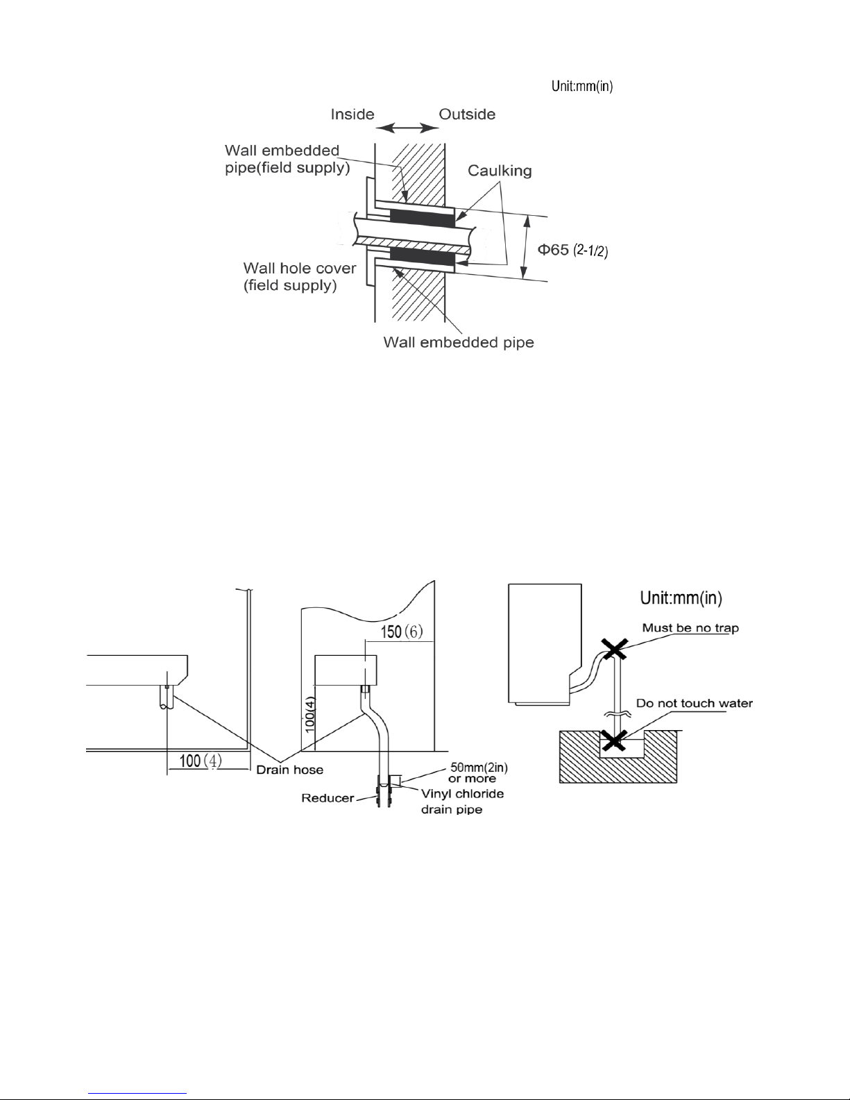
Drain Piping
For the drain pipe, use commercially available rigid polyvinyl chloride pipe general VP 20 pipe with an outer
diameter of 26mm or 1 inch and an inner diameter of 20mm or 13/16 inch.
The drain hose with an outer of diameter 18mm or 3/4 inch at connecting end and is 220mm or 8-11/16 inches
long, is supplied with the indoor unit. Install the drain pipe as pictured below.
The drain pipe should be installed in an inclined downward position, to allow the water to drain and flow freely
without any backup of water. (There must not be any type of trap in the drain hose.)
Insert the drain hose to the depth show below, so it will not be pulled out of the drain pipe.
Insulate the indoor drain pipe with 10mm or 5/16 inch or more of insulation material to prevent condensation.
Remove the air filters and pour some water into the drain pan to check the water drains and flows freely.
Installing Indoor Unit
Preparation
1. Open the front panel.
2. Remove the 4 screws.
3. Remove the front grille while pulling it forward.
4. Follow the arrows to disengage the clasps on the front case to remove it.
5. Follow the procedure shown when removing the slit portions.
15
Page 16
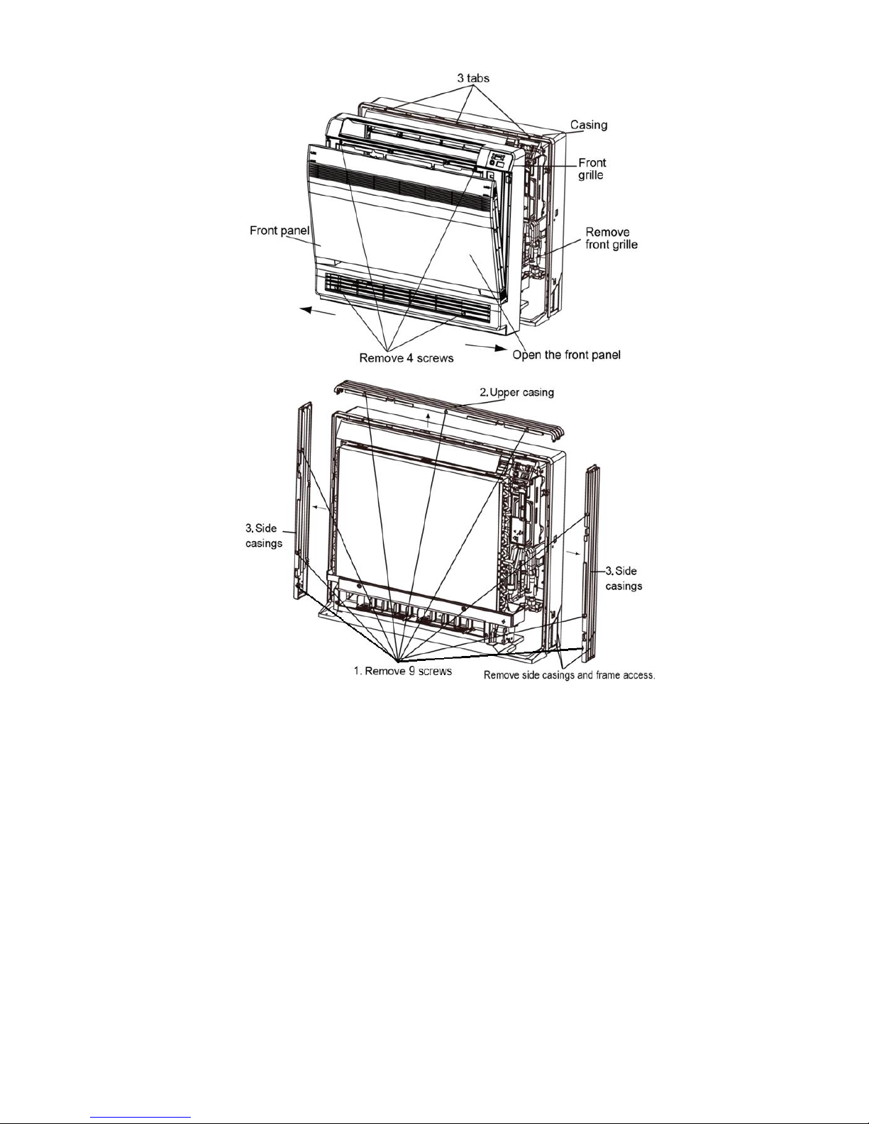
For Moldings
Remove the Side and Top Casings. (Remove the slit portions on the bottom frame, if necessary, using
nippers.)
For Side Piping
Remove the Side and Top Casings.
1. Remove the 9 screws securing the casings.
2. Remove the upper casing by depressing the 2 tabs.
3. Remove the left and right casings by depressing the 2 tabs on each side.
4. Remove the slit portions on the bottom frame, if necessary, and the appropriate casing using nippers.
5. Reassemble by following the above steps in reverse order (4>3>2>1).
16
Page 17
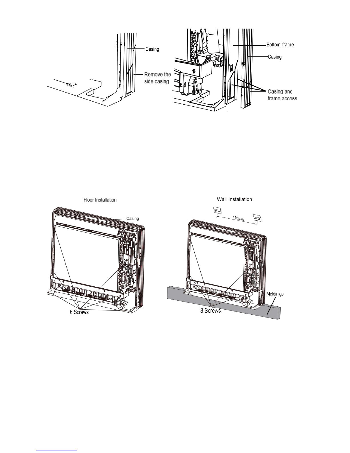
Installation
For floor installations, secure the unit to the floor using 6 screws. (Do not forget to secure the unit to the wall.)
For wall installations, secure the mounting plates using 4 screws and the indoor unit using 4 screws.
The mounting plates must be installed on a wall capable of supporting the entire weight of the indoor unit.
1. Temporarily secure the mounting plate to the wall, making sure the panel is completely level, and mark the
drilling points on the wall.
2. Secure the mounting plates to the wall with screws.
3. Once refrigerant piping and drain piping connections are complete, fill in the gap of the through hole with
putty. A gap can lead to condensation on the refrigerant pipe, and drain pipe, and the entry of insects into the
pipes.
4. Attach the front panel and front grille in their original positions once all connections are complete.
Flaring the Pipe End
1. Cut the pipe end with a pipe cutter while ensuring no debris enters the pipe.
2. Remove burrs from the cut end with the cut surface facing downward to keep chips from entering the pipe.
3. Fit the flare nut onto the pipe.
4. Flare the pipe.
5. Check the flaring and ensure it is made correctly.
17
Page 18
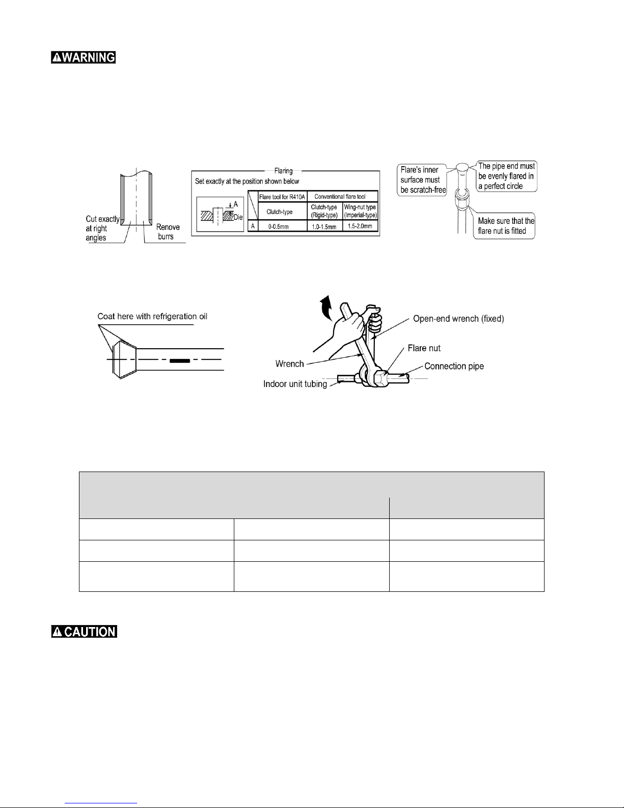
Flare Nut Tightening Torque
Gas side
Liquid side
07/09 class
12/18 class
07/09/12/18 class
3/8 inch
1/2 inch
1/4 inch
32.7-39.9 Nm
(24.1-29.4 Ft.Lbs)
49.5-60.3 Nm
(36.5-44.5 Ft.Lbs)
14.2-17.2 Nm
(10.5-12.7 Ft.Lbs)
Do not use mineral oil on the flared part.
Prevent mineral oil from getting into the system as this would reduce the life expectancy of the units.
Never use piping that has been used for previous installations. Only use parts which are delivered with the unit.
Never install a drier into this R410A unit, as the drying material may dissolve and damage the system and
decrease the life expectancy of the unit.
Poor flaring may cause a refrigerant gas to leak.
Connecting the refrigerant pipe
1. Use torque wrenches when tightening the flare nuts. This will prevent damage to the flare nuts and gas leaks.
2. Align the centers of both flares and tighten the flares. Tighten the flare nuts 3 or 4 turns by hand. Then full
tighten them with the torque wrenches.
3. To prevent gas leakage, apply refrigeration oil on both inner and outer surfaces of the flare.
(Use refrigeration oil for R410A.)
Piping Handling
Protect the open end of the pipe from dust and moisture.
All pipe bends should be as gentle as possible. Always use a pipe bender for bending.
(Bending radius should be 30 to 40mm or 1-1/4 to 1-9/16 inches or larger.)
18
Page 19
Selection of Copper and Heat Insulation Materials
Gas side
Liquid side
Gas pipe thermal insulation
Liquid pipe
thermal insulation
07/09 class
12/18 class
-
07/09 class
12/18 class
-
O.D.9.52mm
(3/8 in)
O.D.12.7mm
(1/2 in)
O.D.6.4mm
(1/4 in)
I.D.12-15mm
(1/2 – 5/8 in)
I.D.14-16mm
(9/16 -5/8 in)
I.D.8-10mm
(5/16 - 7/16 in)
Thickness 0.8mm (1/32 in)
Thickness 10mm (3/8 in) Min.
When using commercial copper pipes and fittings, observe the following:
Insulation material: Polyethylene foam: heat transfer rate:0.041 to 0.052W/mK (0.035 to 0.045kca/(mh℃ )
Refrigerant gas pipe’s surface temperature reaches 110℃ (230℉ ) max.. Choose heat insulation materials that
will withstand this temperature.
Be sure to insulate both the gas and liquid piping lines and to provide adequate insulation. The table below
shows the recommended dimensions.
Use separate thermal insulation pipes for gas and liquid refrigerant pipes.
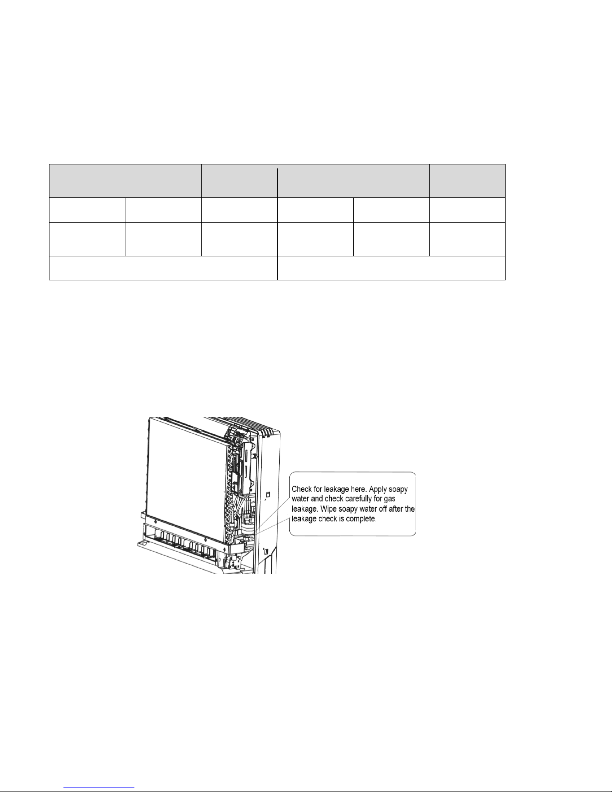
Checking for Gas Leakage
Check for gas leaks after purging the air.
See the sections on air purges and gas leak checks in the installation manual for the outdoor unit.
Attaching the Connection Pipe
Attach the pipe after checking for gas leaks, described above.
1. Cut the insulated portion of the on the side of the piping, matching it up with the connecting portion.
2. Secure the slit on the refrigerant piping side with the butt joint on the auxiliary piping using tape, making sure
there are no gaps.
3. Wrap the slit and butt joint with the included insulation sheet, making sure there are no gaps.
19
Page 20
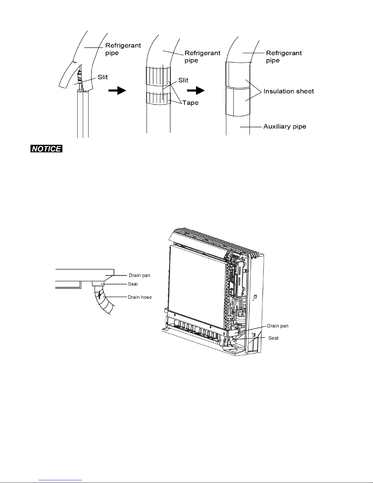
Insulate the joint of the pipes and secure. Incomplete or improper insulation may lead to condensate leakage.
Push the pipe inside to prevent it from placing undue force on the front grille.
Connecting the Drain Hose
Insert the supplied drain hose into the socket of the drain pan.
Fully insert the drain hose into the socket until it adheres and seals.
With a Multi indoor unit, install as described in the installation manual supplied with the outdoor unit.
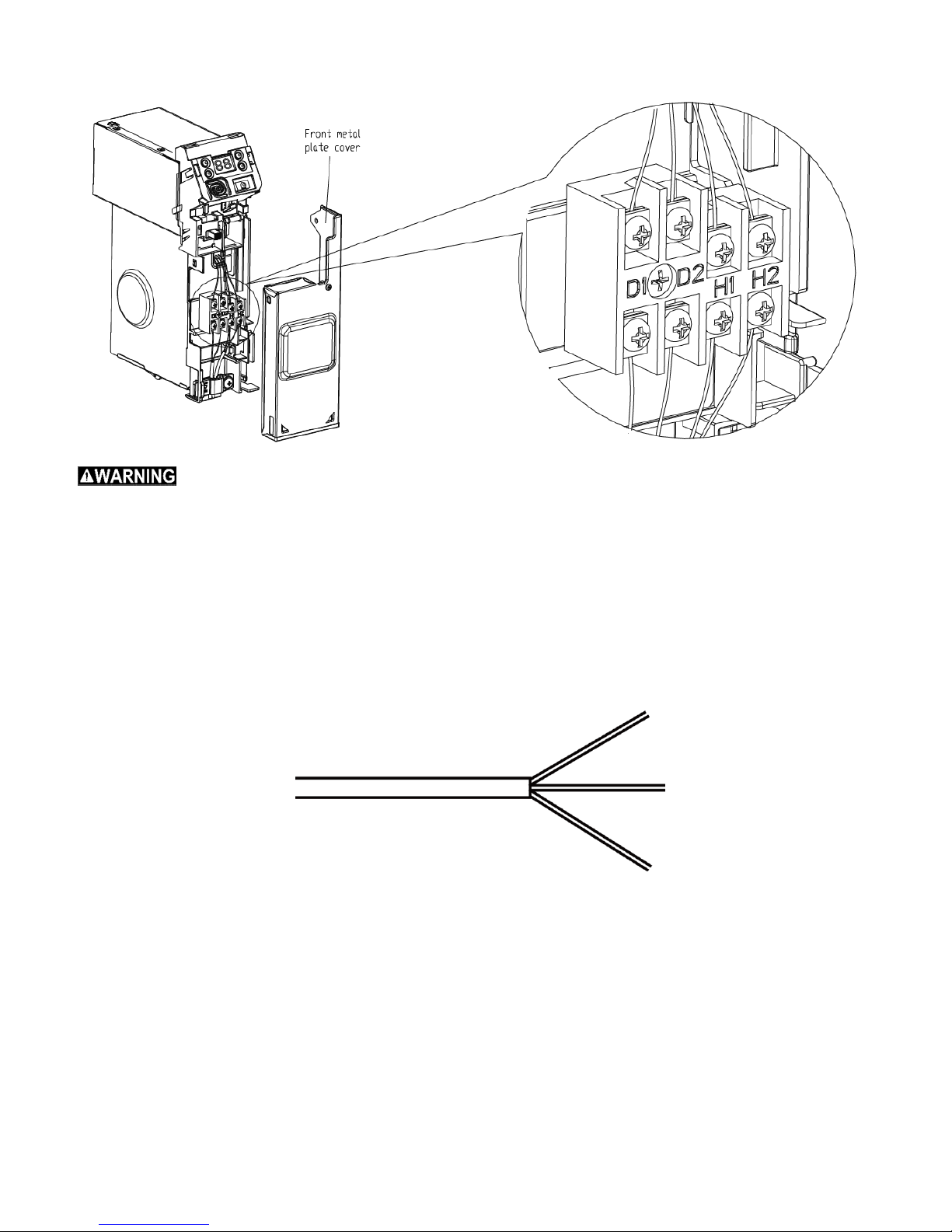
Lift the sensor securing plate, remove the front metal plate cover, and connect the wire to the terminal board.
1. Open the cover of electric box of indoor unit.
2. Route the communication line across the rubber ring.
3. Connect the communication line to terminal D1 and D2 on the wiring board of indoor unit.
4. Secure the communication line with the wire clamp on the electric box. Pull wires to make sure that they are
attached securely, then secure the wires with a wire retainer.
20
Page 21
The power of every indoor unit should be on its own circuit/power supply.
Do not use tapped wires, stranded wires, extension cords, or starburst connections, as they may cause
overheating, electrical shock, or fire.
Do not use locally purchased electrical parts inside the unit. (Do not branch the power for the drain pump, etc.,
from the terminal block.) Doing so may cause electric shock or fire.)
1. The power connection cord has been inserted on the mainboard through the piping hole of the chassis.
Please connect the power connection cord with the breaker. If the power cord is not long enough, please
lengthen using a terminal block.
2. Reinstall the wire cover to its original place and tighten.
3. Recover the surface panel.
21
Page 22
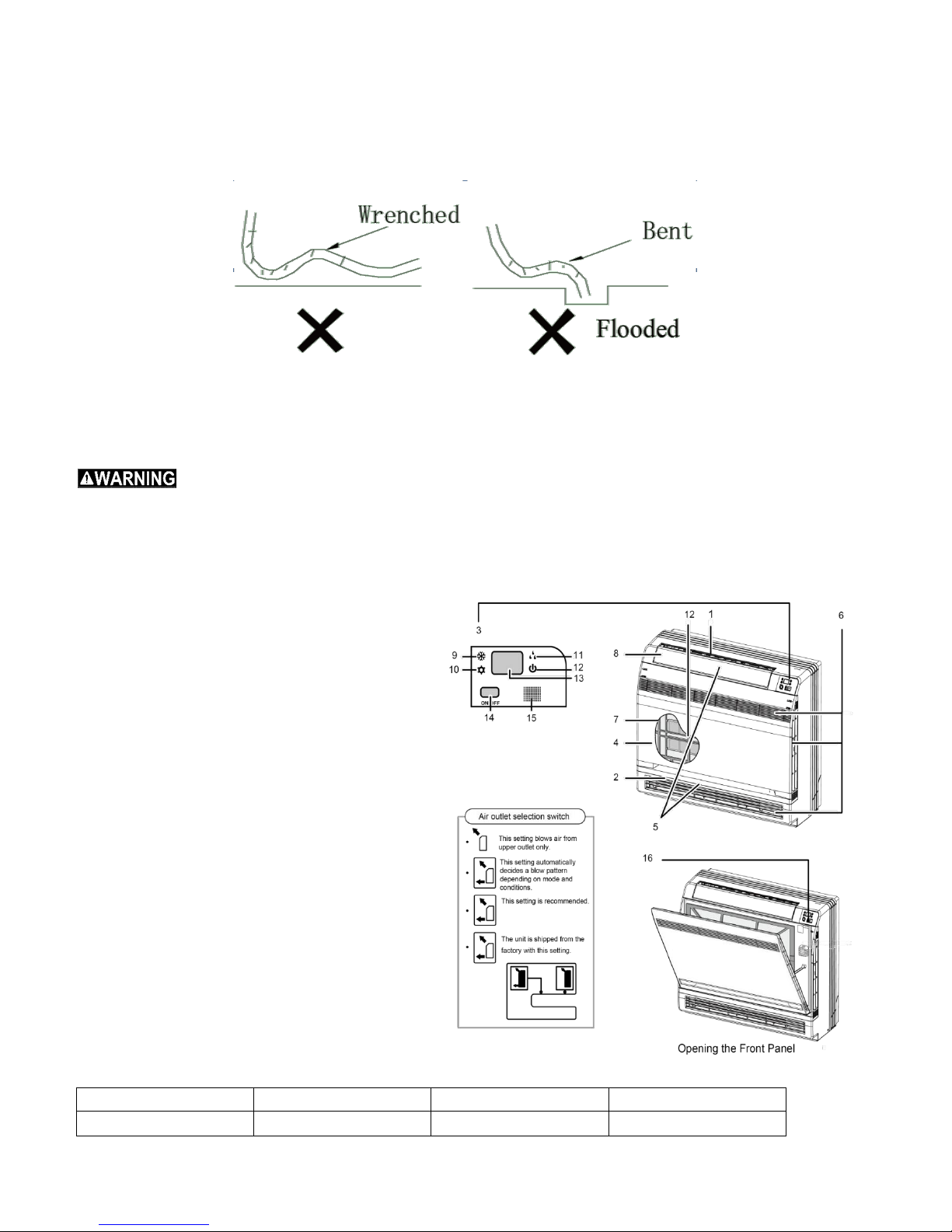
Install the drainage pipe
Model
Mode
Temperature setting
Air flow rate
HEAT PUMP
AUTO
26°C(78.8°F)
AUTO
(1). For correct draining, the drain hose should be slanted downward.
(2). Do not wrench or bend the drain hose or place the open end into water.
(3). Wrap with heat resistant material when connecting the longer drainage tube though to the indoor unit.
Install the Refrigeration Pipes
Connect the refrigeration pipes with the two relative leading pipes, tighten the nut on the refrigeration pipes
securely.
Be careful when bending the connecting pipes and avoid creating flats and wrinkles within the bend radius as
this will damage the pipes.
Do not over tighten/torque the flare nut. Over tighten/torqueing can cause the flare nut to leak.
Component Identification
1. Titanium Apatite Photocatalytic Air-Purifying
Filter:
These filters are attached to the inside of the unit.
2. Air outlet
3. Display
4. Front panel
5. Louvers (vertical blades)
These louvers are inside of the air outlet.
6. Air inlet
7. Air filter
8. Flap (horizontal blade)
9. Cool mode lamp
10. Heat mode lamp
11. Dry mode lamp
12. Run lamp
13. LED display
14. Indoor Unit ON/OFF switch:
Push this switch once to start operation.
Push once again to stop it.
The operation mode refers to the following
table.
22
Page 23
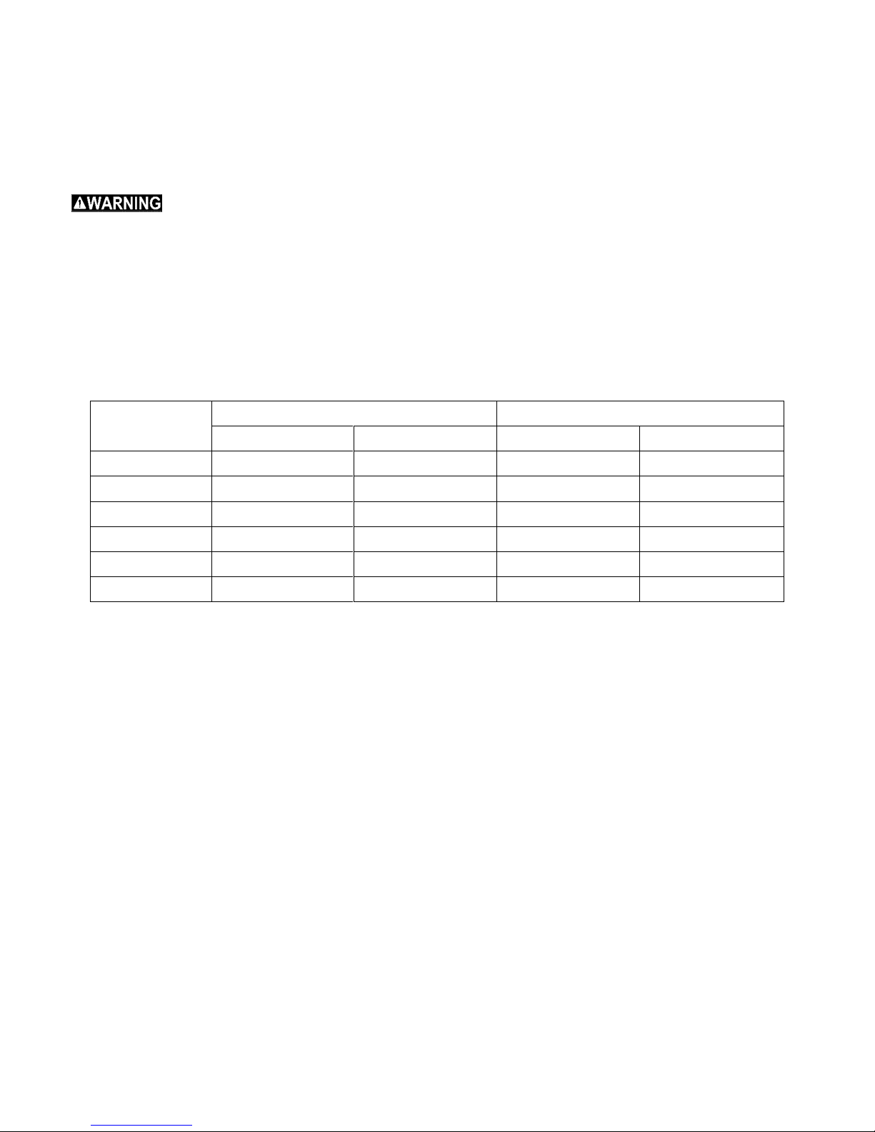
This switch is useful when the remote controller is missing.
Indoor side state
Outdoor side state
Dry bulb temp °C(°F)
Wet bulb temp °C(°F)
Dry bulb temp °C(°F)
Wet bulb temp °C(°F)
Rated Cooling
27(80.6)
19(66.2)
35(95)
24(75.2)
Max. cooling
32(89.6)
23(73.4)
43(109.4)
26(78.8)
Min. cooling
21(69.8)
15(59)
18(59)
—
Rated Heating
20(68)
15(59)
7(44.6)
(42.8)
Max. heating
27(80.6)
—
24(75.2)
18(64.4)
Min. heating
20(68)
15(59)
-15(5)
-16(3.2)
15. Signal receiver:
a. It receives signals from the remote controller.
b. When the unit receives a signal, you will hear a short beep.
c. Settings change the beep.
16. Air outlet selection switch.
Before opening the front panel, be sure to stop unit operation and turn the breaker OFF.
Do not touch the metal parts on the inside of the indoor unit, as an injury may result.
If the power supply cord is damaged, it must be replaced by the manufacturer or an approved equivalent
and installed by a qualified technician to avoid an electrical shock.
The unit must be installed in accordance with national and local wiring codes.
An all-pole disconnection switch having a contact separation of at least 3mm in all poles should be
connected in the fixed wiring.
Working Temperature Range
23
Page 24
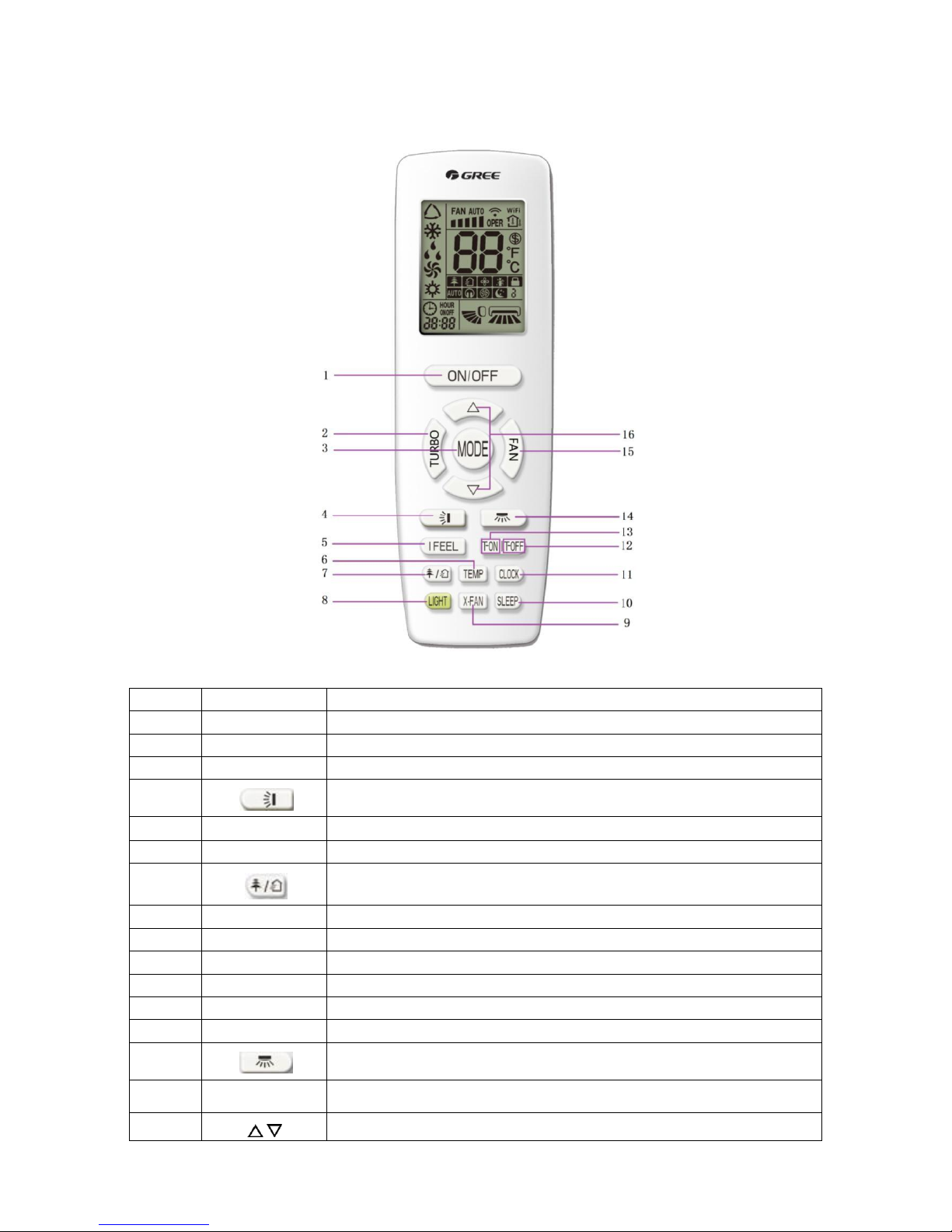
Remote Controller YAP1F
No.
Button name
Function
1
ON/OFF
Turn on or turn off the unit
2
TURBO
Set turbo function
3
MODE
Set operation mode
4
Set up & down swing status
5
I FEEL
Set I FEEL function
6
TEMP
Switch temperature displaying type on the unit’s display
7
Set health function and air function
8
LIGHT
Set light function
9
X-FAN
Set X-FAN function
10
SLEEP
Set sleep function
11
CLOCK
Set clock of the system
12
TOFF
Set timer off function
13
TON
Set timer on function
14
Set left & right swing status
15
FAN
Set fan speed
16
Set temperature and time
/
Button Name and Function Introduction
24
Page 25
Preparation Before Operation
When using the remote controller for the first time or after replacing the batteries, please set the time of the system
according to current time in the following steps:
1. Pressing CLOCK button, is blinking.
2. Pressing or button, the clock time will increase or decrease rapidly.
3. Press CLOCK button again to confirm the time and return to display current time.
Introduction of operation functions
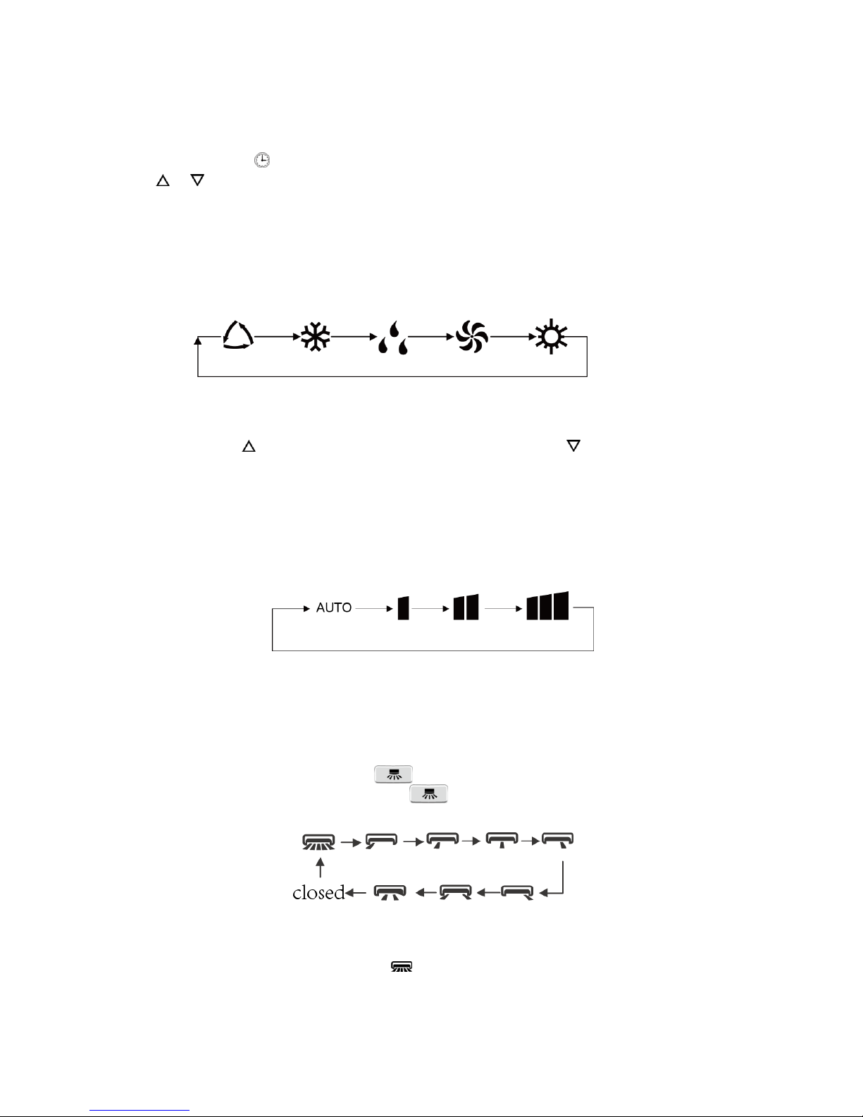
1. Selecting operation MODE:
In unit on status, press MODE button to select operation mode in the following sequence:
2. Setting Temperature:
In unit on status, press ▲ button to increase set temperature and press ▼ button to decrease set temperature.
In unit on status, press button to increase setting temperature and press button to decrease setting
temperature. The range of temperature is from 16°C to 30°C or 60.8°F to 86°F.
Note: Under AUTO MODE, manual adjustment of temperature is not required.
3. Adjusting Fan Speed:
In unit on status, press the FAN button to adjust the fan speed in the following sequence:
When operation mode changes, the fan speed is memorized.
Under dry mode, the fan speed is low and cannot be adjusted.
4. Setting Swing Function:
Setting left and right SWING
1). Under simple SWING status, press button to adjust left and right swing status.
2). Under fixed-angle SWING status, press button to adjust left and right SWING angle circularly
as below:
Note: Operates continuously left and right swing in 2 seconds, swing states will change accordingly to the above-
displayed order or switch to closed state and state.
25
Page 26
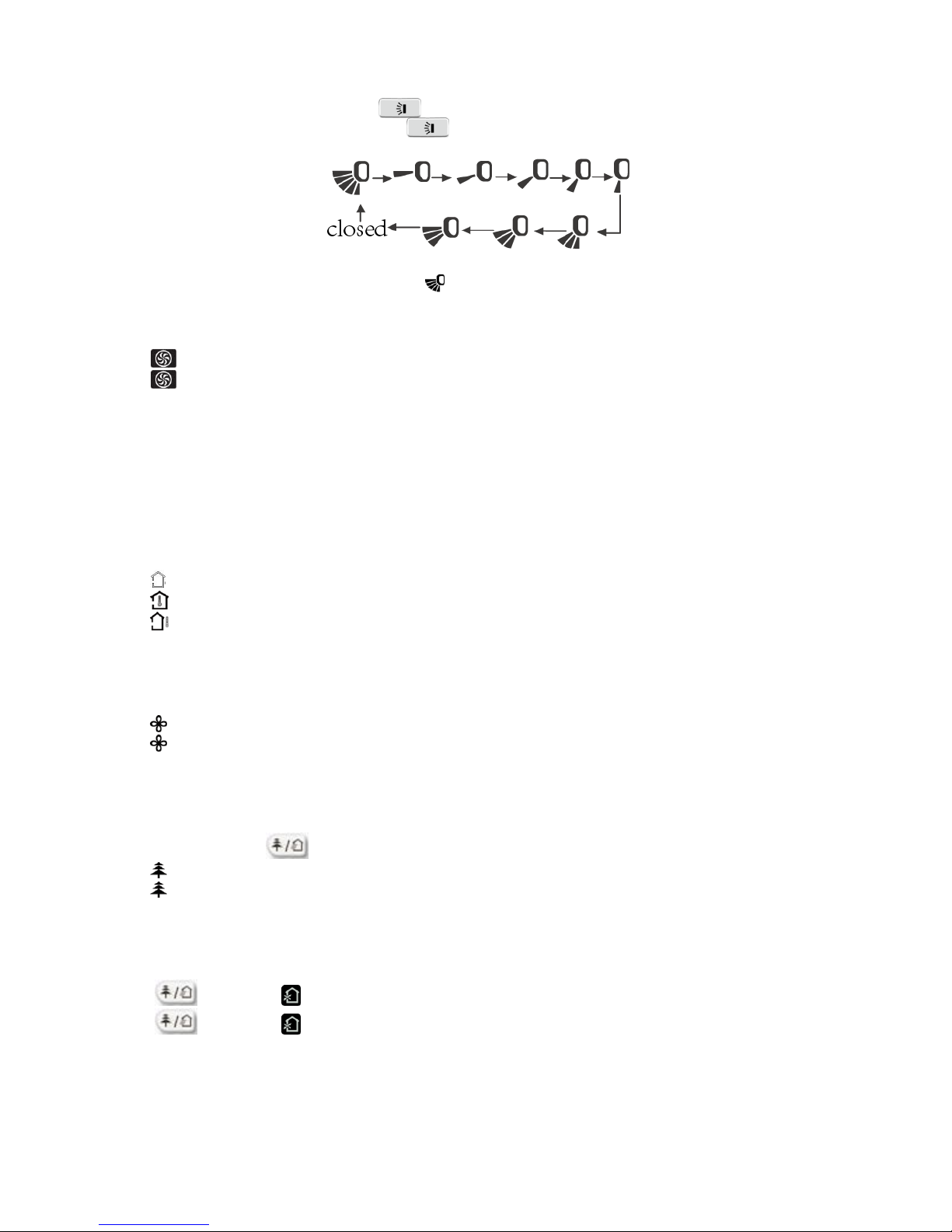
Setting up and down SWING:
1. Under simple SWING status, press button to adjust up and down SWING status;
2. Under fixed-angle SWING status, press button to adjust up and down SWING angle
circularly as below:
Note: Operate continuously left and right SWING in 2 seconds, swing states will change accordingly to above-
mentioned order, or switch closed state and state;
5. Setting TURBO function:
Under cool or heat mode, press TURBO button to set TURBO function.
When is displayed, TURBO function is on.
When is not displayed, TURBO function is off.
When TURBO function is on, the unit operates in super high speed to achieve rapid cooling or heating. When
TURBO function is off, the unit operates in normal fan speed setting.
6. Setting LIGHT function:
The LIGHT on the receiver light board will display present operating status. If you want to turn off the LIGHT,
press the LIGHT button. Press this button again to turn on the LIGHT.
7. Viewing Ambient Temperature:
In unit on status, the receiver light board or wired controller is defaulted to display the setting temperature.
Press TEMP button to view indoor or outdoor ambient temperature.
When is displayed, it means the displayed temperature is setting temperature.
When is displayed, it means the displayed temperature is indoor ambient temperature.
When is displayed, it means the displayed temperature is outdoor ambient temperature.
Note: Setting temperature is always displayed on Remote Controller.
8. Setting X-FAN function:
In cool or dry mode, press X-FAN button to set X-FAN function.
When is displayed, X-FAN function is on.
When is not displayed, X-FAN function is off.
When X-FAN function is on, the water on the evaporator will be blown away until the unit is turned off to avoid
mildew.
9. Setting health function:
In unit on status, press button to set the health function.
When is displayed, health function is on.
When is not displayed, health function is off.
Health function is available when the unit is equipped with an ION generator. When health function is on, the
ION generator will start operation, adsorbing dusts and killing the bacteria in the room.
10. Setting air function:
Press button until is displayed, then the air function is turned on.
Press button until is disappeared, then the air function is turned off.
When the indoor unit is connected with a fresh air valve, air function setting can control the connection of fresh
air valve, which can control the fresh air volume and improve the air quality inside the room.
26
Page 27
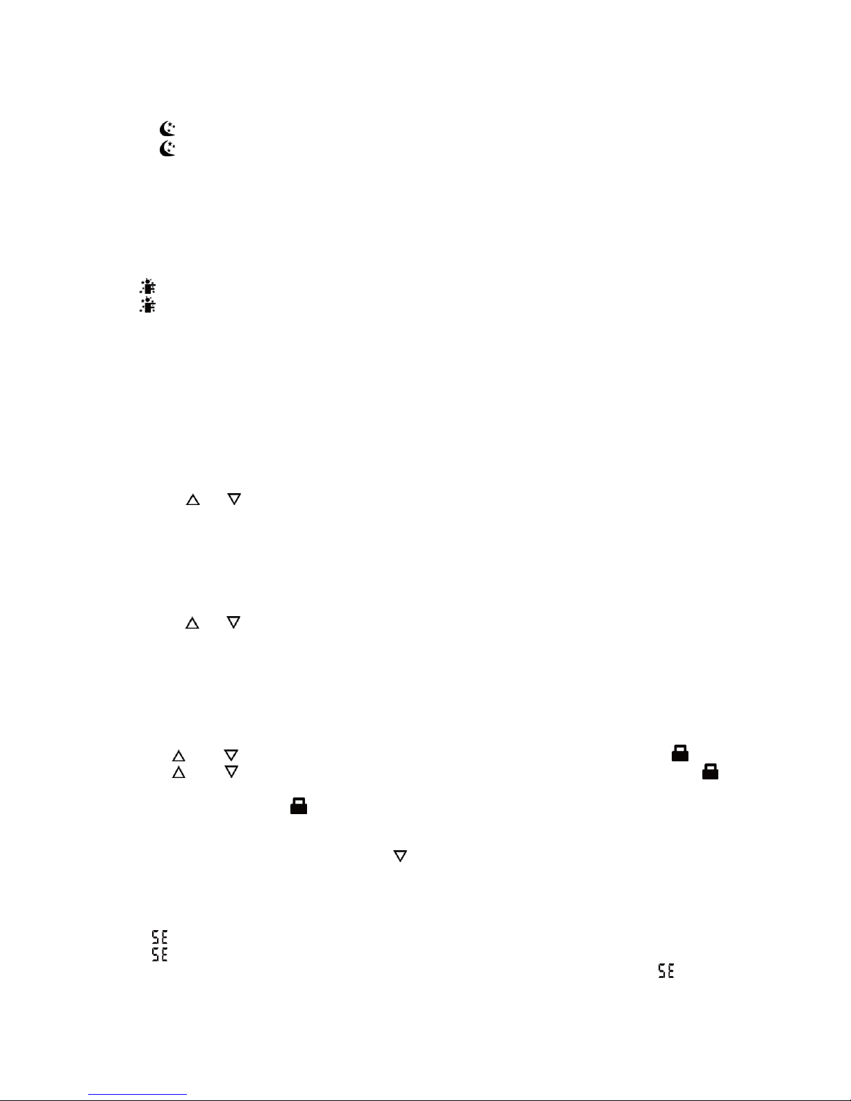
11. Setting sleep function:
In unit on status, press SLEEP button to turn on or turn off sleep function.
When is displayed, the sleep function is on.
When is not displayed, the sleep function is off.
Notes:
1. Sleep function cannot be set in auto and fan mode;
2. When turning off the unit or switching mode, sleep function is cancelled.
12. Setting I FEEL function:
In unit on status, press I FEEL button to turn on or turn off I FEEL function.
When is displayed, I FEEL function is on.
When is not displayed, I FEEL function is off.
When I FEEL function is turned on, the unit will adjust temperature according to the temperature detected by
the remote controller to achieve the best air-conditioning effect. In this case, you should place the remote
controller within the valid receiving range.
13. Setting timer:
You can set the operation time of unit as needed. You can also set timer ON and timer OFF in combination.
Before setting, check if the time of the system is the same as the current time. If not, set the time according to
the current local time.
1). Setting timer off:
I. Pressing TOFF button, “OFF” is blinking and time displaying zone displays the timer time of last setting.
II. Press or button to adjust the timer time.
III. Press TOFF button again to confirm setting. OFF is displayed and time displaying zone resumes to
display current time.
IV. Press TOFF button again to cancel timer and OFF is not displayed.
2) Setting timer on:
I. Pressing TON button, “ON” is blinking and time displaying zone displays the timer time of last setting.
II. Press or button to adjust the timer time.
III. Press TON button again to confirm setting. ON is displayed and time displaying zone resumes to display
current time.
IV. Press TON button again to cancel timer and ON is not displayed.
Introduction of Special Functions
1. Setting child lock:
1) Press and button simultaneously to lock the buttons on the remote controller and is displayed.
2) Press and button simultaneously again to unlock the buttons on remote controller and is not
displayed.
3) If the buttons are locked, blinks 3 times when pressing the button and any operation on the button is
invalid.
2. Switching temperature scale:
1) In unit off status, press MODE button and button simultaneously to switch temperature scale between
℃ and ℉.
3. Setting energy-saving function:
1) In unit on status and under cool mode, press CLOCK and TEMP buttons simultaneously to enter energysaving mode.
When is displayed, energy-saving function is on.
When is not displayed, energy-saving function is off.
To turn off the energy-saving function, press CLOCK and TEMP buttons simultaneously and is not displayed.
Note: Energy-saving function is only available in cooling mode and it will exit when switching modes or setting
sleep function.
27
Page 28
4. Absence function:
In unit on status and under heat mode, press CLOCK and TEMP buttons simultaneously to enter absence
function. Temperature displaying zone displays 8 and .
Press CLOCK and TEMP button simultaneously again to exit absence function. Temperature displaying zone
resumes previous display and is not displayed.
In winter, absence function can keep the indoor ambient temperature above 0°C (32℉) to avoid freezing.
Absence function is only available in heating mode and it will exit when switching modes.
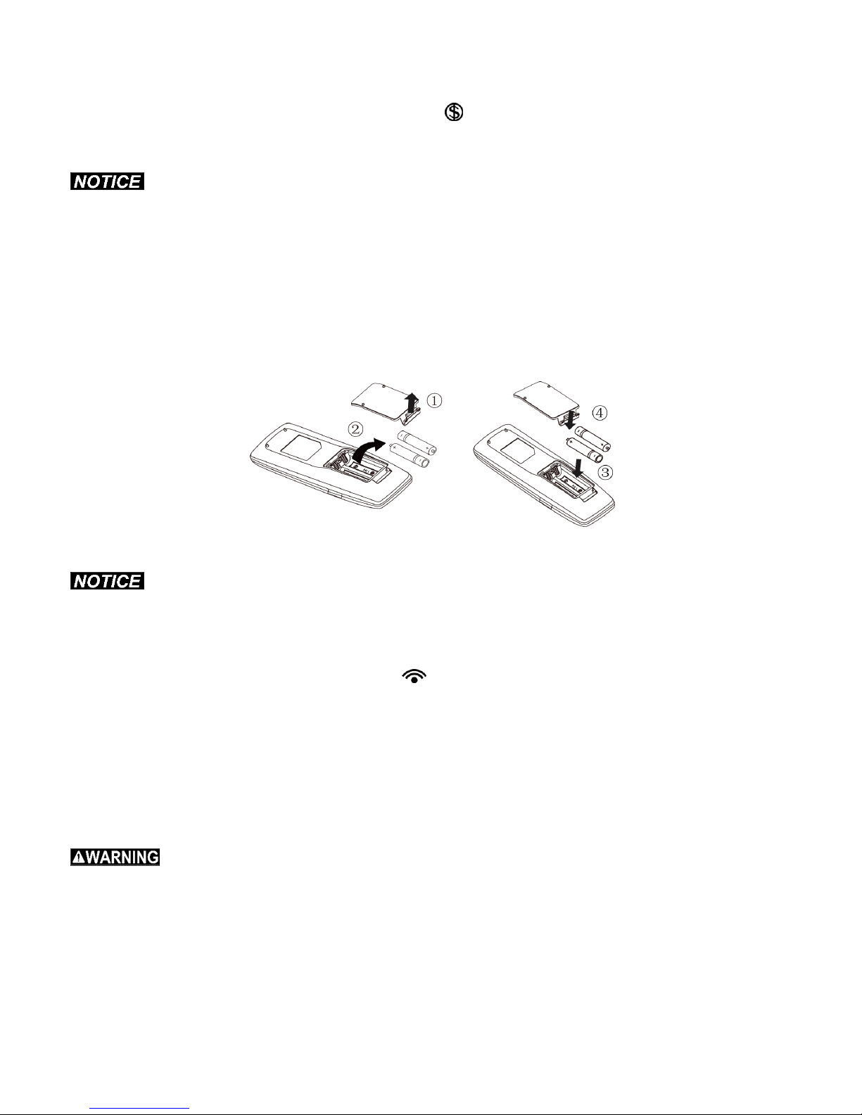
Replacing Batteries in Remote Controller and Notes
1. Lift the cover along the direction of arrow (as shown in Fig 1①).
2. Take out the original batteries (as shown in Fig 1②).
3. Place two (AAA 1.5V) dry batteries, and make sure the battery position of “+” polar and “-” polar is correct (as
shown in Fig 2③).
4. Reinstall the cover (as shown in Fig 2④).
Fig.1 Fig.2
The remote controller should be placed 1m(3’ 3”) away from the TV set or stereo.
The operation of the remote controller must be performed within its receiving range.
If you need to control the main unit, point the remote controller at the signal receiving window on the main unit
to improve the receiving sensitivity of main unit.
When the remote controller is sending a signal, “ ” icon will be blinking for 1 second. When the main unit
receives a valid remote-control signal, it will sound.
If the remote controller does not operate normally, take the batteries out and reinsert them after 30 seconds. If
it still does not operate properly, replace the batteries.
When replacing the batteries, do not use old or different types of batteries, as this may cause the unit to
malfunction.
When the remote controller will not be in use for a long time, please take out the batteries.
Maintenance Method
Before inspection and maintenance of the unit. Please set power switch to “OFF” to cut off the power supply.
Units
Indoor unit, Outdoor unit and Remote controller
Wipe them with dry soft cloth.
28
Page 29
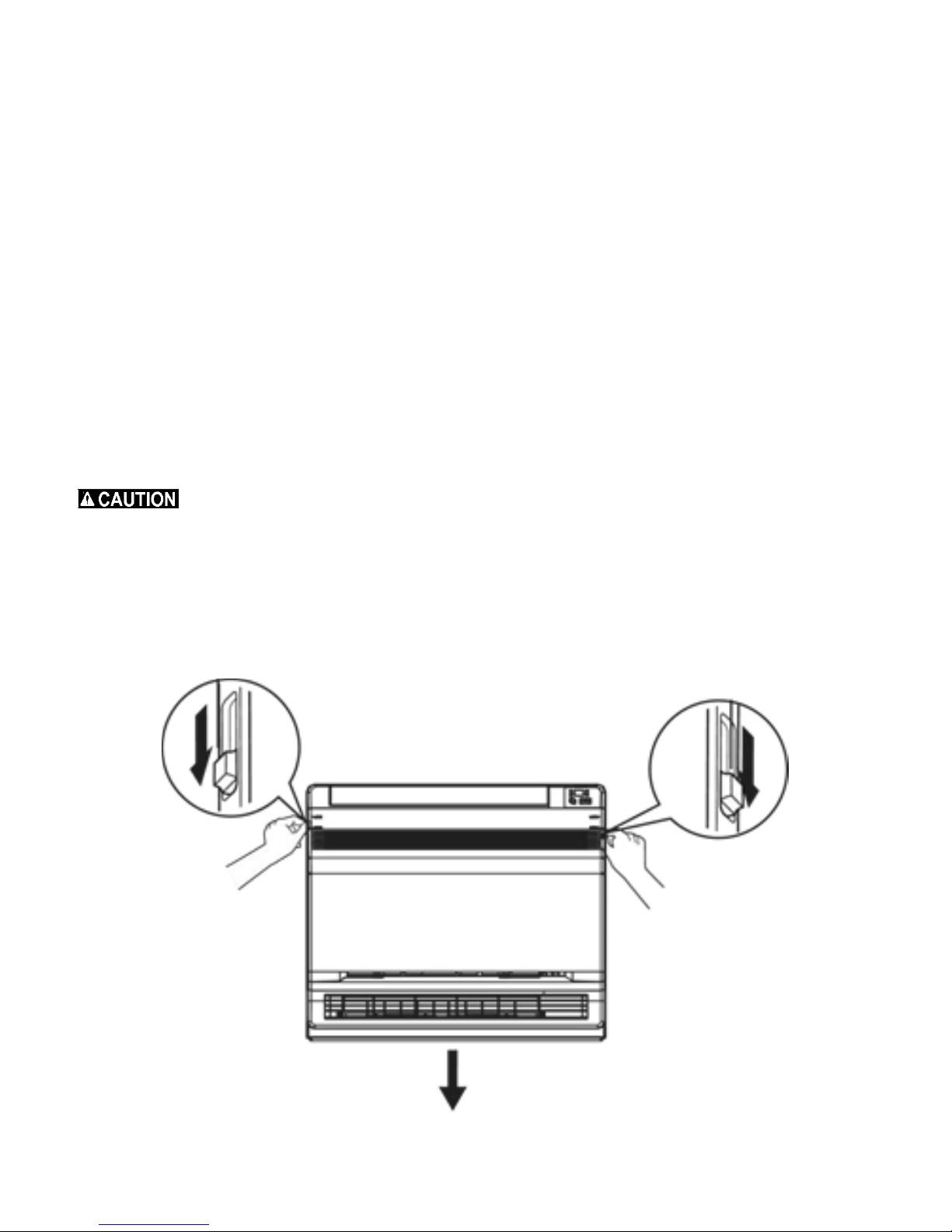
Front Panel
1. Open the front panel.
2. Remove the air filter.
Slide the two stoppers on the left and right sides inward until they click.
3. Remove the front panel.
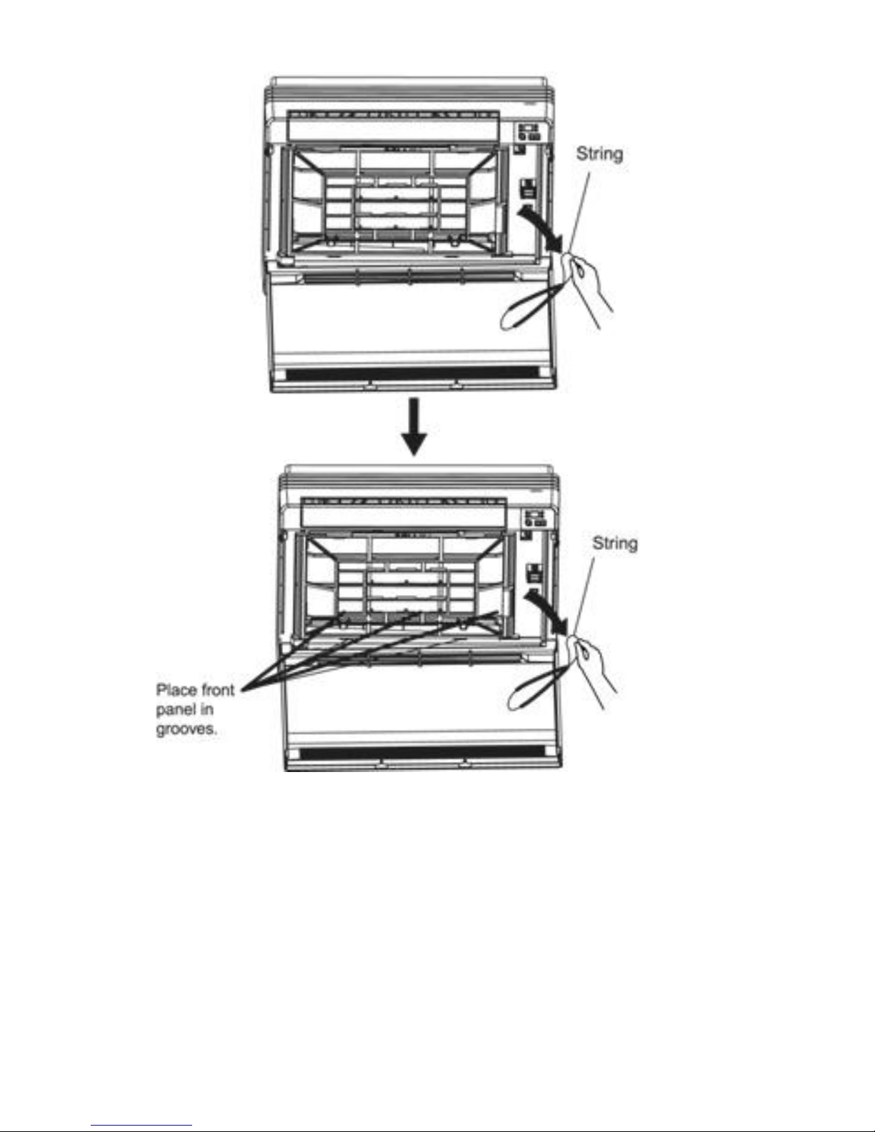
Remove the string.
Allow the front panel to fall forward and then you can remove it.
4. Clean the front panel.
Wipe it with a soft cloth soaked in water.
Only neutral detergents can be used.
When washing the front panel with water, dry it with a clean soft cloth when finished.
5. Attach the front panel.
Insert the front panel into the grooves of the unit (3 places).
Attach the string to the right, inner-side of the front grille.
Close the panel slowly.
Don’t touch the metal parts of the indoor unit as some of the edges might be sharp and may cause an injury.
When removing or attaching the front panel, use a ladder if necessary when the unit is mounted on the ceiling.
When removing or attaching the front panel, support the panel securely with hand to prevent it from falling.
For cleaning, do not use water above 40°C (104°F), benzine, gasoline, thinner, nor other volatile oils, polishing
compound, scrubbing brushes, or any other abrasives.
After cleaning, make sure the front panel is secured.
29
Page 30
30
Page 31
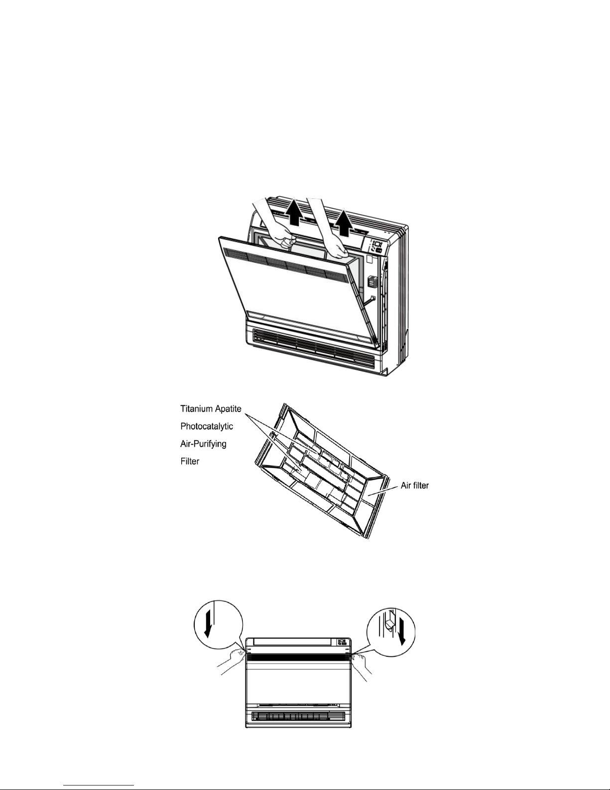
Filters
1. Open the front panel.
2. Remove the air filter.
I. Press the tabs down slightly on the air filter frame, located on the right and left, while pulling air filter away
from the unit.
3. Take off the Titanium Apatite Photocatalytic Air-Purifying Filter.
I. Hold the tabs of the air filter frame and remove from the 4 retaining tabs. 2 of the 4 tabs are larger and
located at the top of the air filter frame and 2 of the 4 are smaller and are located approximately in the
middle of the air filter frame.
4. Clean or replace the filter.
5. When cleaning is complete, or a new filter is required, attach the air filter and Titanium Apatite Photocatalytic
Air-Purifying Filter as they were prior to cleaning and close the front panel.
Operation without air filters can result in clogged coils and reduced efficiencies and can also have a
negative impact on other components inside the unit reducing its life span.
31
Page 32
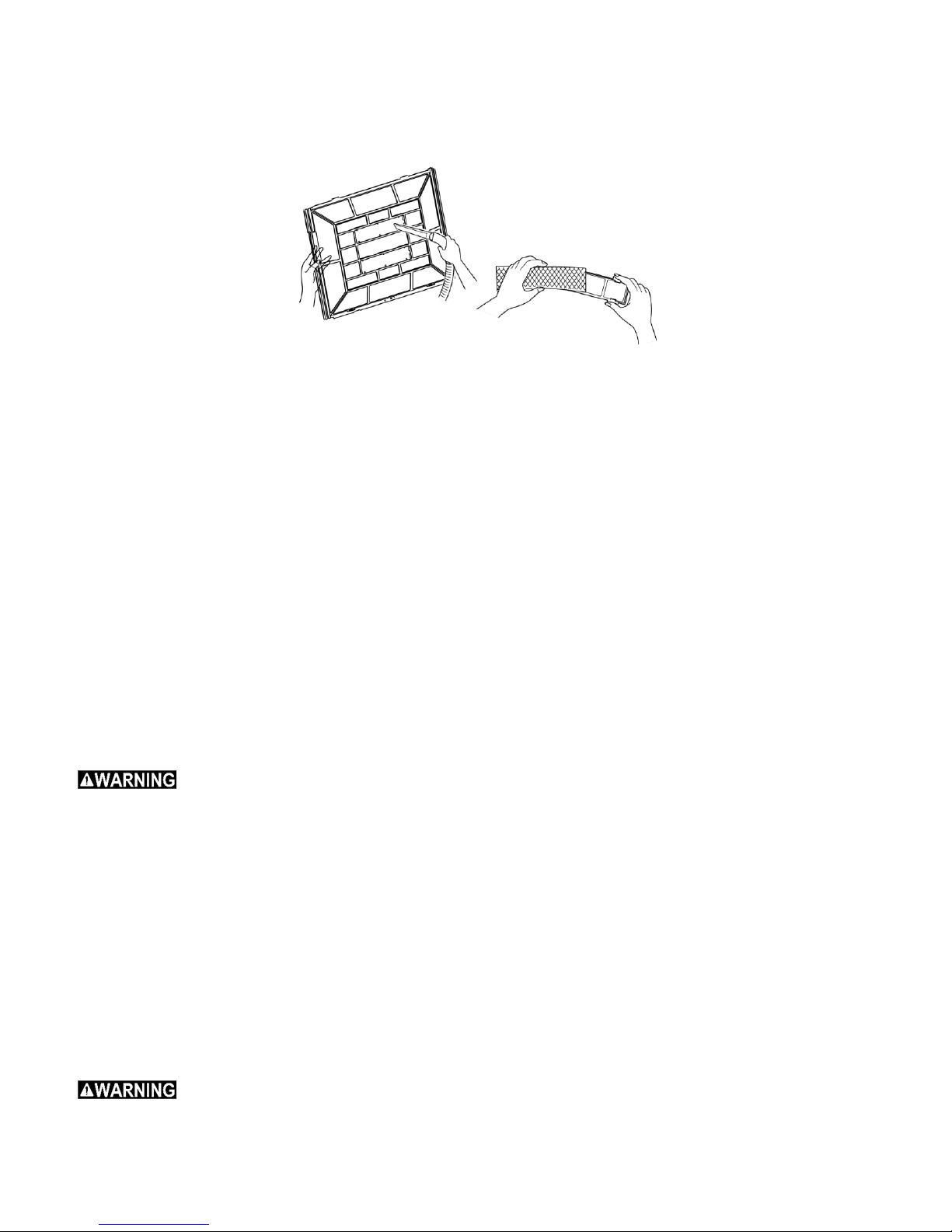
6. Wash the air filters with water or clean them with vacuum cleaner
I. If the dust does not come off easily, wash them with a neutral detergent and lukewarm water, then allow
the filter to air dry thoroughly in a place not exposed to direct sunlight.
II. It is recommended to clean the air filter every week.
Titanium Apatite Photocatalytic Air-Purifying Filter
The Titanium Apatite Photocatalytic Air-Purifying Filter can be renewed by washing it with water once every 6
months. It is recommend replacing the filter once every 3 years.
Vacuum dusts, and soak in warm water for about 10 to 15 minutes if it is very dirty.
Do not remove filter from frame when washing with water.
After washing, shake off remaining water and allow it to dry in a place not exposed to direct sunlight.
The filter material is made of paper. Do Not wring out the filter after washing or soaking.
Replacement
Remove the filter and replace with a new filter.
Dispose of the old filter as flammable waste.
Notes: Operation with dirty filters.
1. Cannot deodorize the air.
2. Cannot clean the air.
3. Results in poor heating or cooling.
4. May cause odor.
1. If no drain water is seen, water may be leaking from the indoor unit. Stop operation contact a qualified service
technician.
2. Check that the base/stand and other fittings of the outdoor unit are not corroded or incorrectly installed.
3. Ensure there is nothing blocking the air inlets or outlets of the indoor unit and the outdoor unit.
4. Ensure the condensate drains smoothly out of the drain hose during COOL or DRY operations.
Before a Long Idle Period
1. Operate the “FAN only” for several hours on a dry day to ensure the inside is completely dry.
I. Press “MODE” button and select “FAN” operation.
II. Press “ON/OFF” button and start operation.
2. After operation stops, turn off the breaker for the room air conditioner.
3. Clean the air filters and reinstall them.
4. Take out batteries from the remote controller.
When a multi outdoor unit is connected, make sure the heating operation is not used at the other room before you use the fan
operation.
32
Page 33
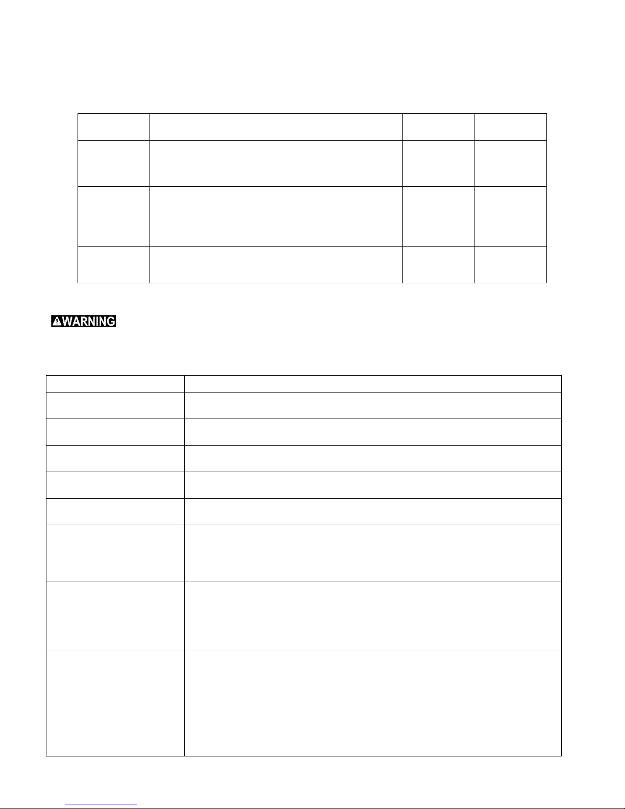
Function Description of Functional Dial Switch S7
Dial switch
Silk screen
Function
Dial ON
Dial OFF
1(S / R)
Selection of memory mode:
Election between reset mode and standby mode after
energizing;
This function is available without wired controller.
Standby after
energizing
Reset after
energizing
2(L / I)
Selection between manual controller and receiver:
If manual controller is selected, remote-control function
of receiver will be shielded.
If receiver is selected, wired controller will be non-
effective.
Selecting
wired
controller
Selecting
receiver joint
3(M / S)
Setting of main and slave indoor units:
For resolution of conflict among the modes;
This function is available without wired controller.
Main indoor
unit
Slave indoor
unit
Malfunction Phenomena
Malfunction Analyzing
The air conditioner will not start
right after being turned off.
The over load protect switch of the unit places the unit in a 3 mins delay, after which the
unit will start normally.
There is an odor when the unit
is turned on.
This is because when air conditioning, odors or cigarette smoke from the room that were
pulled into the unit are being discharged into the tom again.
Slight bicker was heard when
the unit is running.
This is the sound for inner refrigerant flowing.
Mist comes from the air outlet
vent when cooling.
Indoor air is being cooled rapidly.
Creaking sound is heard when
unit is running or after running.
The grating sound is caused by the expansion of panels and other metal parts in the unit
due to a change in temperature within the unit.
The air conditioner will not run.
Is power off?
Is the power supply connected?
Is the circuit protector tripped?
Is the voltage too high or too low?
If TIMER had been set in wireless remote controller?
The cooling/heating effect of
the air conditioner is not as
expected.
Is the temperature set too high or too low?
Is the inlet or outlet vent of outdoor unit blocked?
Is the air filter dirty causing a blockage?
Are all windows and doors closed?
Is the fan set to Low speed?
Are there other heating sources in the room?
Wireless remote controller will
not control the unit.
Changed the batteries, the wireless remote controller sometimes will appear as though it
can’t control. Take off the back cover and press the ACL button to make it normal.
The air conditioner is operating abnormally or changing functions too frequently, making
the wireless remote controller ineffective. Reset the breaker supplying power to the unit
and the unit should resume normal operation.
Is the controller within the receiving area? Or is there smoothing blocking the signal?
Check batteries in wireless remote controller and ensure they are the correct type and size
recommend for the remote controller. If not, change the batteries.
1. The 3-bit dial switch must be set before energizing the main board and it determines running state of indoor
unit.
2. Function of it is as follow:
Analyzing Malfunctions
DO NOT REPAIR the air conditioner yourself. An incorrect repair could lead electric shock or fire. Contact a certified service
center or technician and have the unit repaired by specially personnel. Check the following items before contacting a service
technician to repair you unit, as this could save your time and expense.
33
Page 34

Service Center
When the following phenomena appeared, stop operating immediately, turn off the main power supply of unit and
contact qualified service center or technician to check the unit.
Harsh sound heard when running.
The fuse or protector trips frequently.
Moisture has been pulled into the unit involuntarily.
Water leakage in the room.
Overheating of the power cord.
Odor is noticed when unit is running.
RECOMMENDED TOOLS FOR INSTALLATION
1. Mounting Indoor & Outdoor Units and Running Piping/Wiring
Ruler
Stud-Finder
Dry-Wall Saw
Electric Drill
3” Hole Saw
Drill Extension
Hammer Drill and Bit
Measuring Tape
Level
Flash Light
Screw Driver (Phillips and Flat)
Hammer
Knife
Scissors
Goggled Glasses
Mask
Gloves
Ladder
2. Refrigeration Related Work
Flat Surface Wrench (Two)
Flare-Nut Tool Set
Hex Head Key Set
Torch for AC Application
Heat Absorption Flux
Nitrogen
Soap Bubble
Vacuum Pump
Helium Leakage Check
Manifold
3. Electrical Related Installation
Wire Cutter
Wire Stripper
Sharp Plier
Cable Ties
Black Tape for Electrical Use
Electrical Meter
4. Trial Running Units and Inspection
Clamp Meter
Manifold
Infrared Thermometer
USER NOTES AND INSTALLATION/SERVICE/MAINTENANCE NOTES
34
Page 35
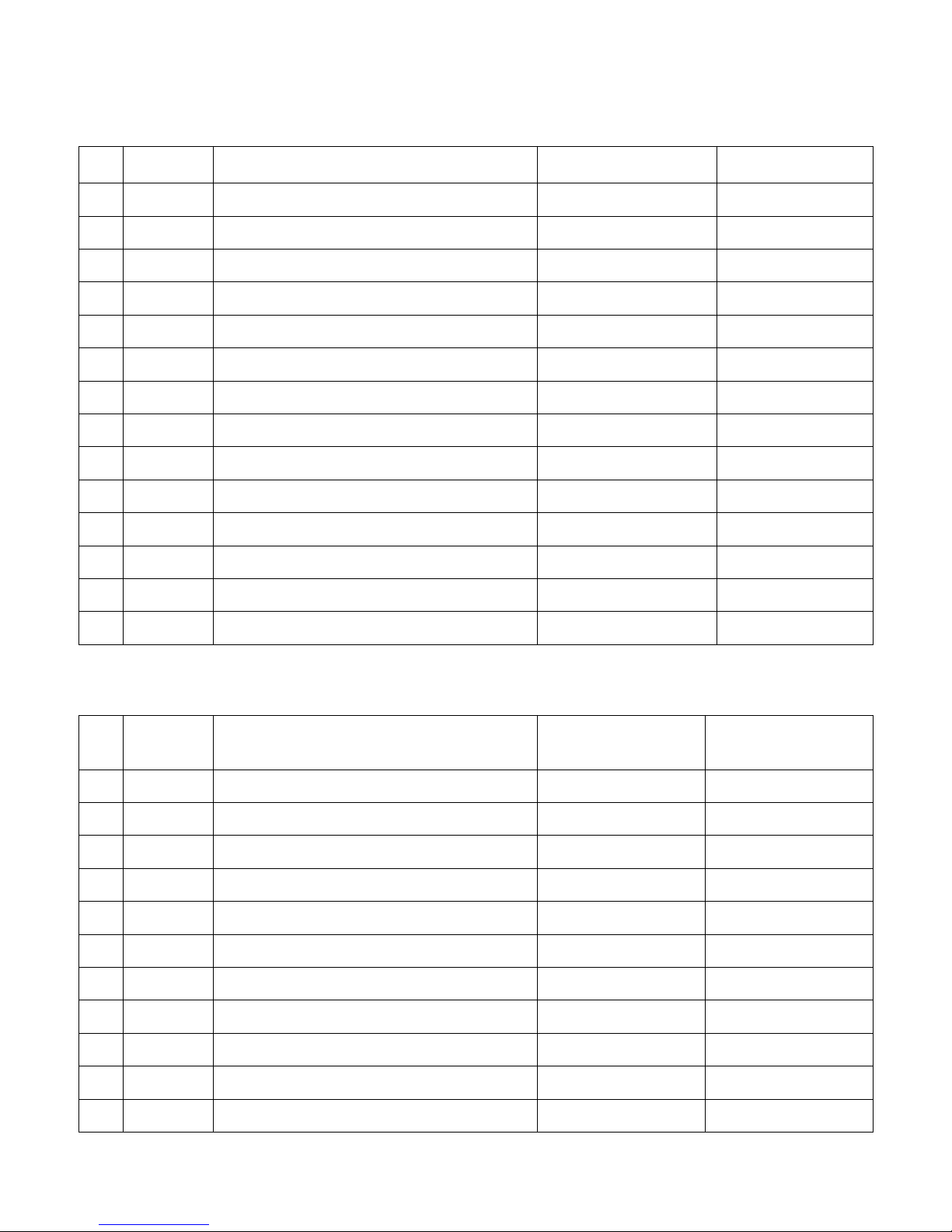
No.
Date
Noes
Asked Your
Technician for Help?
Did You Ask YMGI
Tech. for Help?
No.
Date
Installation Company Name, Technician
Name, Phone & HCAC License #
Job Not Performed
by Technician
Technician
Checklist
Completed Fully?
INSTALLATION NOTES
Please list any questions or issues you may have with this unit:
USER NOTES
Please list any questions or issues you may have with this unit:
35
Page 36
SERVICE / MAINTENANVE NOTES
No.
Date
Contents of Service / Maintenance
Technician’s Company Name, Technician
Name, Phone & HCAC License #
Please list any questions or issues you may have with this unit:
After-Sales/Service
When having quality or other problems when purchasing the air conditioner, please contact the local service center.
36
 Loading...