

Page 1
:
YILMAZ
ADRES
:
TELEFON
:
TELEFAX
:
- :
:
MARKASI
:
MODEL KODU
:
: : :
:
: ADRES
:
TELEFON
:
TELEFAX
:
- :
0216.312.28.28 PBX
0216.484.42.88
PVC
YILMAZ
CA 601
2 YIL
-
Page 2
EC Declaration of Conformity
MANUFACTURER : YILMAZ MACHINERY INDUSTRY &TRADE CO
-ISTANBUL- TURKIYE
Declare on our own responsibility that ;
CA 601 PVC CORNER CLEANING MACHINE
Meets all the provisions of the 2006/42 EC Machinery Directive, 2006/95 EC Low Voltage Directive, and 2004/108
EC EMC Directive which apply to it
Page 3
d
D
CA 601
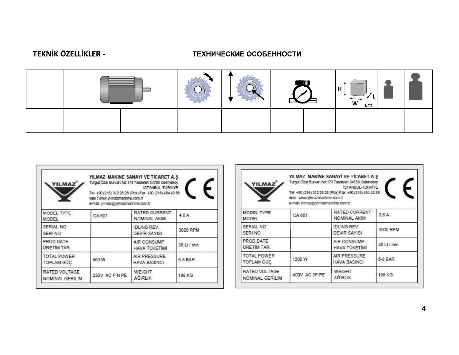
TECHNICAL FEATURES -
860 W 50 Hz
230 V AC P N PE
1200 W 50 Hz
400 V AC 3P PE
3000
D/dak.
RPM
D = 215 mm
max.
d = 32 mm
6/8 Bar
36
Lt. / dak.
Lt/min
W = 92
L = 101
H = 143
kg kg
198 249
Page 4
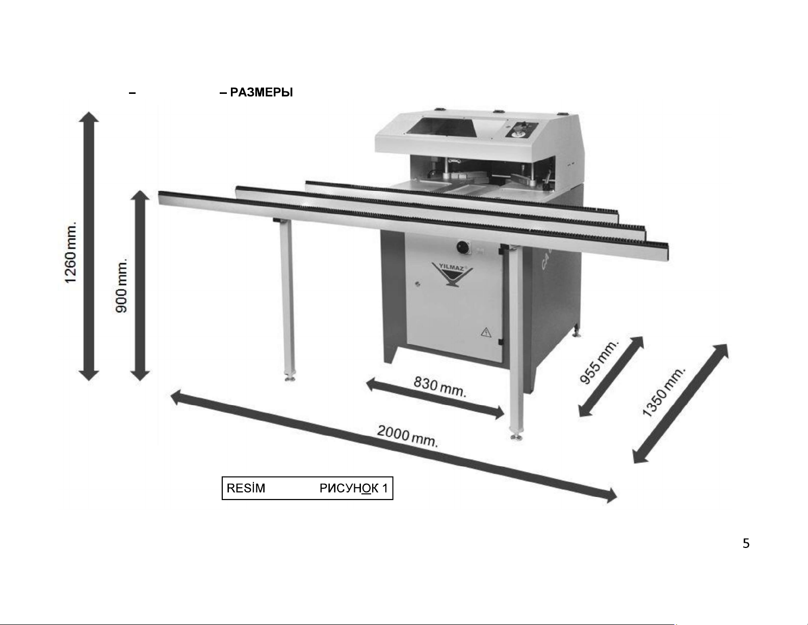
BOYUTLAR DIMENSIONS
-FIGURE-
Page 5
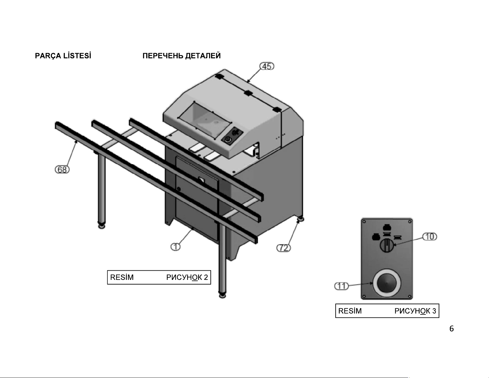
- PART LIST -
-FIGURE-
-FIGURE-
Page 6
-FIGURE-
-FIGURE-
Page 7
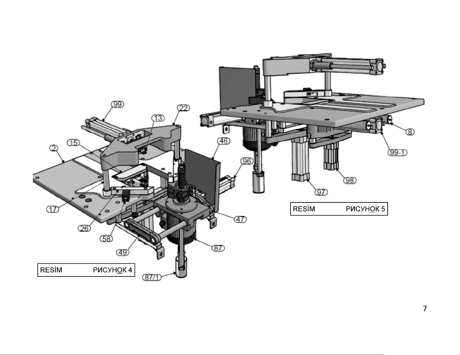
-FIGURE-
Page 8
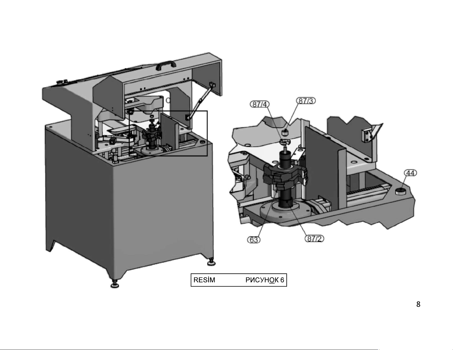
NO
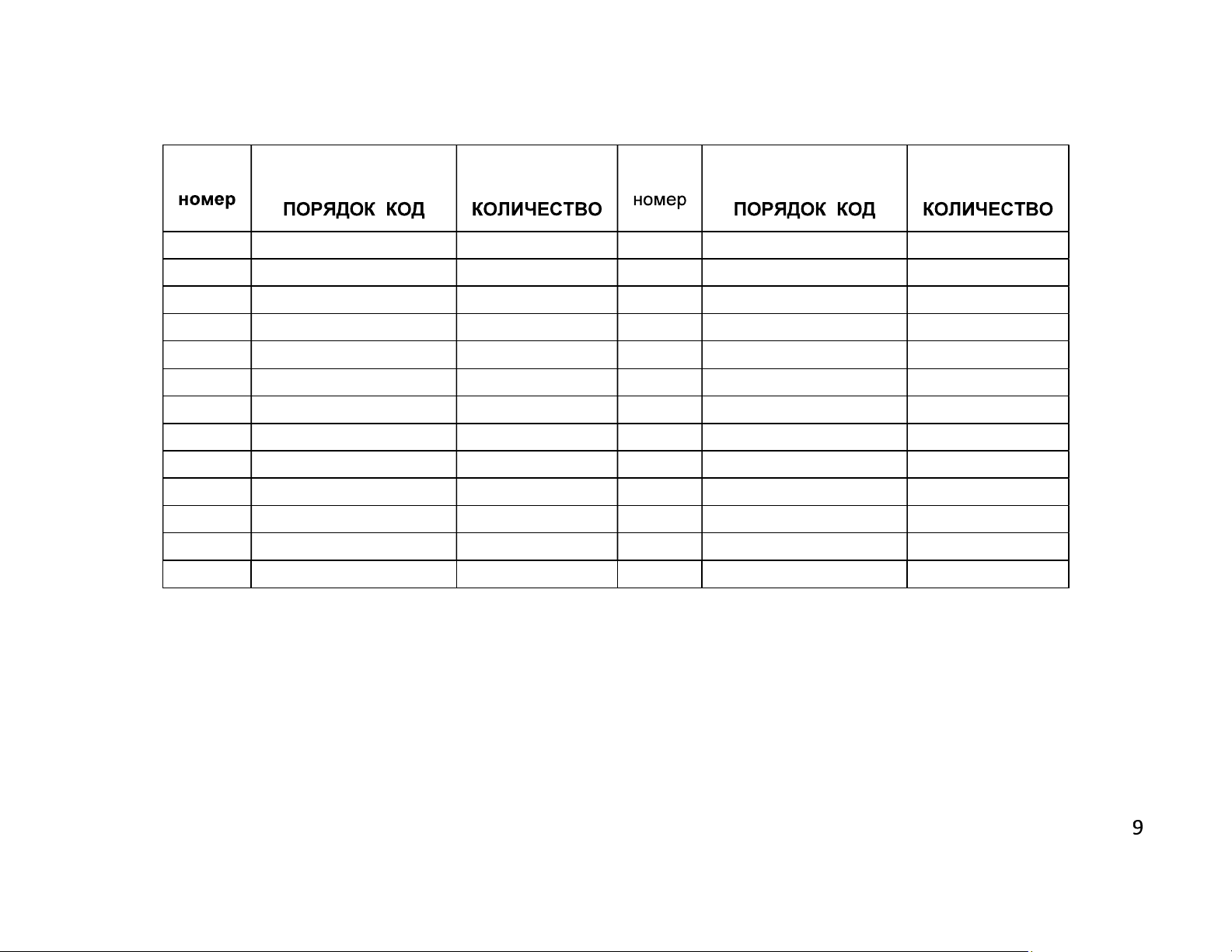
1 1SA010000-0053 1 87 3UA630030-0003 1
2 2TU012510-0328 1 87-1 3UA140030-0007 1
8 3UA060030-0014 2 87-3 2TU011110-0042 1
13 1SK060000-0004 2 87-4 2TU011110-0040 1
15 2TU011210-0474 1 96 1PN020000-0131 1
17 2TU014010-0116 1 97 1PN020000-0132 1
22 2TU012510-0332 1 98 1PN020000-0129 1
26 2TU012210-0054 1 99 1PN020000-0143 1
46 1SA050000-0185 1 99-1 1PN020000-0143 1
47 2TU012510-0337 1
49 2TU012510-0338 1
STOK KODU
STOCK CODE
ADET
QTY
NO
STOK KODU
STOCK CODE
ADET
QTY
63 2TU011110-1101 1
72 1SC170000-0007 1
Page 9
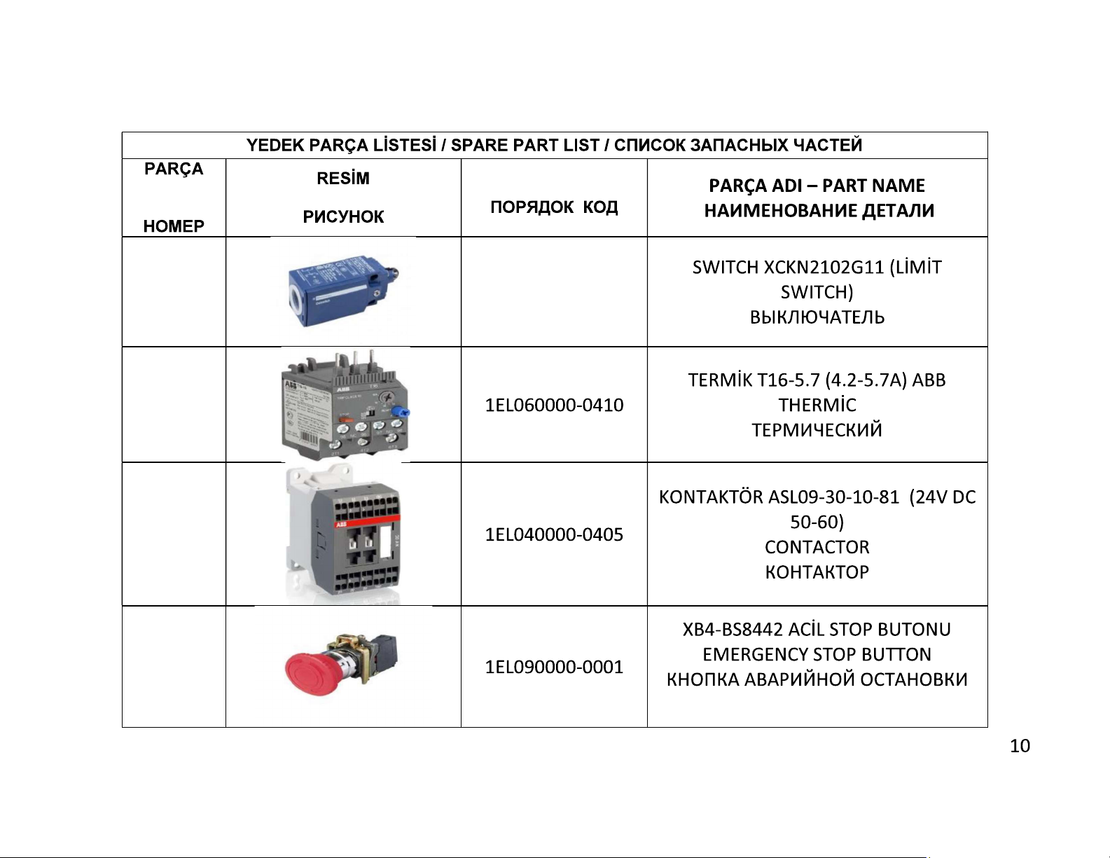
NO
PART NO
PICTURE
STOK KODU / CODE
1
2
3
4
1EL020000-0012
Page 10
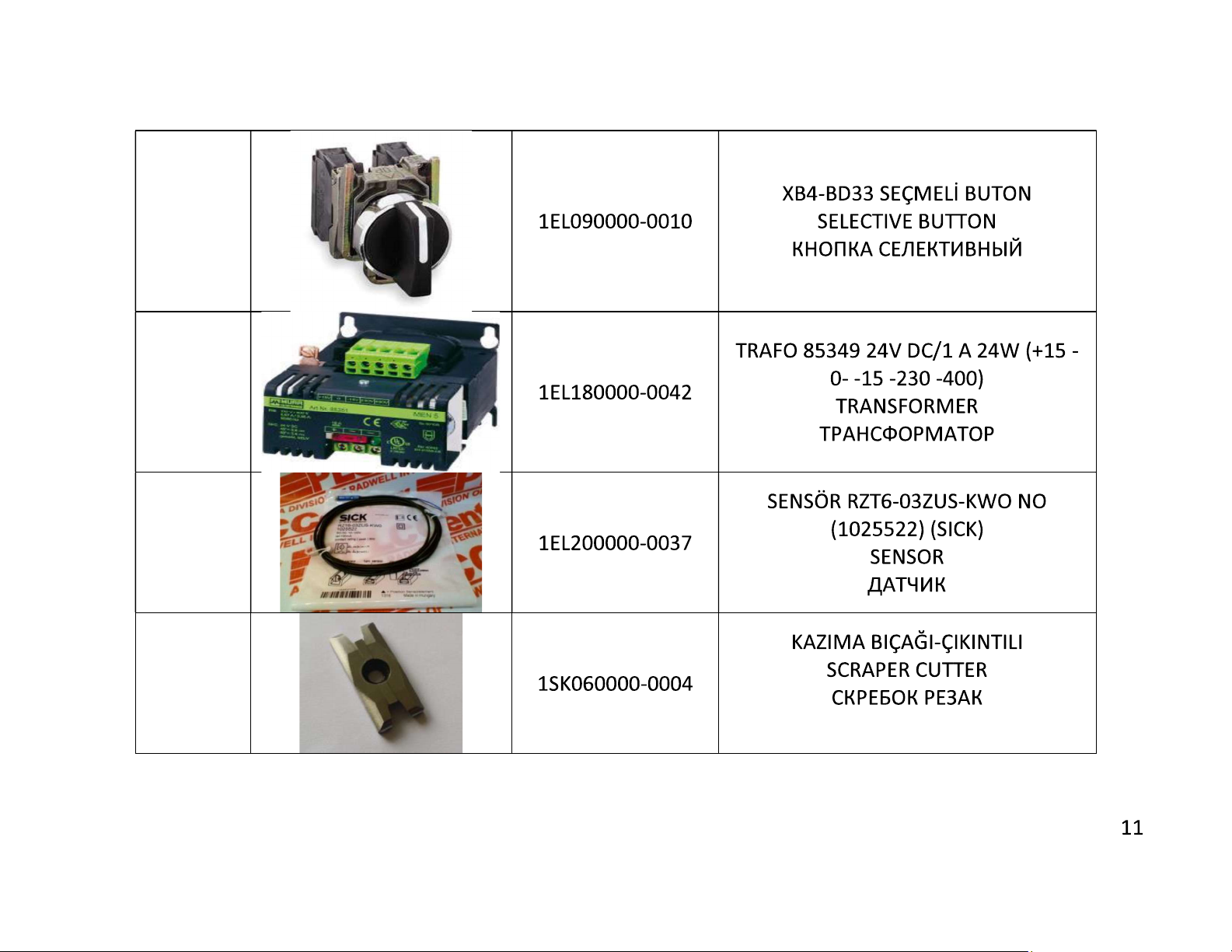
5
6
7
8
Page 11
CONTENTS
1. General information
1.1. Introduction
1.2. Service Information
2. Safety
2.1. Safety Symbols and Their Meanings
2.2. Accidents Prevention
2.3. General Safety Information
3.
4. Transport of the Machine
5. Installation of the Machine
5.1. Preparation
5.2. Connecting to Power Source
6.
7. Operation
7.1 Preparation
7.2 Operation
8. Maintenance, Service and Repair
8.1 Maintenance
8.2 Changing the cutting tool
8.3 Adjust the air pressure
9. Trouble Shooting Guide
10. Warranty conditions
ENGLISH
Page 12
1. GENERAL INFORMATION
1.1. Introduction
operator should read these instructions carefully, and the machine should be operated after fully understanding them.
Safe and efficient use of the machine for long term depends on understanding and following the instructions contained in
this manual. The technical drawings and details contained in this manual constitute a guide for the operator.
1.2. Service Information
In case of any technical problem please contact your nearest YILMAZ dealer, or YILMAZ head office through the above
mentioned phone, fax or e-mail address.
Technical labels with the model description of the machine are fixed onto the front side of each machine.
rial number and manufacturing year are stipulated on the technical label.
Average life usage of production is 10 years. If you have any further failure and complaint, please inform to our
below mentioned technical service by verbal or written
Page 13
AUTHORIZED TECHNICAL SERVICE CENTER ADDRESS
Tel
Fax
E-mail
Web
For minimize the documantation, It is wery necessary to mention below details at the agreements signed with suppliers and
dealers of the purchased machines
0216 312 28 28 Pbx.
0216 484 42 88
www.yilmazmachine.com.tr
Machine model Voltage and frequency
Date of purchase
Description of the machine fault Name of dealer where machine was purchased
Average daily operation period
Page 14
2. SAFETY
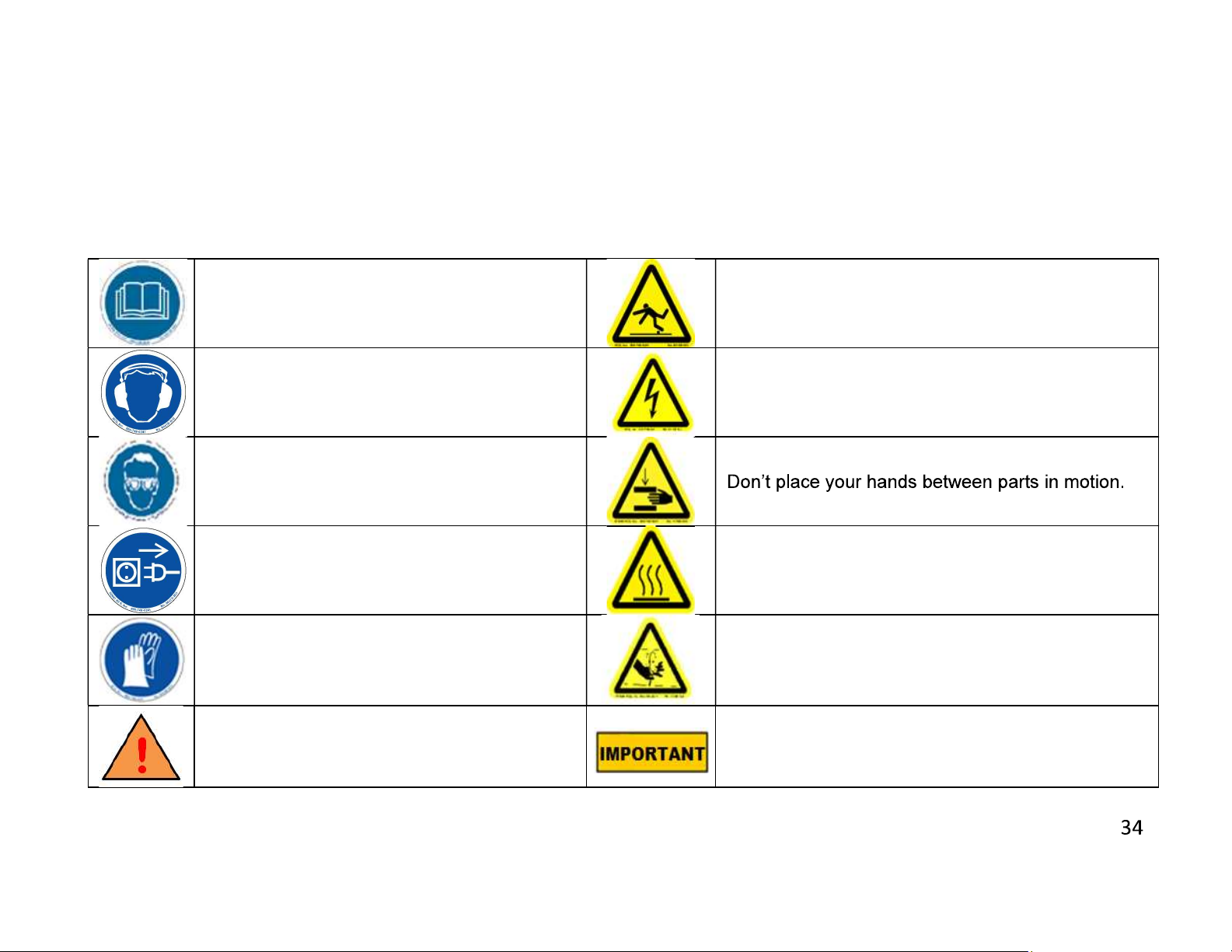
2.1. Safety Symbols and Their Meanings
Read the user guide
Wear ear protectors
Wear safety goggles
If the power cable should be damaged
during operation, don't touch and unplug it.
Never use damaged power cables.
During saw blade change operations, use
protective gloves
The above symbol DANGER WARNING,
warns you against specific dangers, and you
have definitely to read them..
Ensure safe working position, always keep your
balance.
Elektrical excitation
.
High temperature warning
Keep your fingers clear of the movable parts of the
glide arm.
The IMPORTANT symbol above is one telling to
apply special care and to be careful at carrying out
the specified operation
Page 15
2.2. Accidents Prevention
2.2.1 Our machines are manufactured in accordance with CE safety directives, which cover national and international
safety directives.
2.2.2 It is the task of the employer to warn his staff against accident risks, to train them on prevention of accidents, to
provide for necessary safety equipment and devices for the
2.2.3 It is the task of the employer to warn his staff against accident risks, to train them on prevention of accidents, to
2.2.4 Machine should be operated only by staff members, who have read and understood the contents of this manual.
2.2.5 All directives, recommendations and general safety rules contained in this manual have to be observed fully.
The machine cannot be operated in any way for purposes other than those described herein. Otherwise, the
manufacturer shall not be deemed responsible for any damages or injuries. And such circumstances would lead
to the termination of the warranty
2.3. General Safety Information
2.3.1 The power cable should be led in such a way that nobody can step on it or nothing can be placed on it. Special
care has to be taken regarding the inlet and outlet sockets
2.3.2
accordance with the stipulated values.
2.3.3 Use correct illumination for the safety of the operator. (ISO 8995-89 Standard The lighting of indoor work
system)
Page 16
2.3.4 Use correct illumination for the safety of the operator. ( ISO 8995-89 Standard The lighting of indoor work
system)
2.3.5
machine.
2.3.6 Ensure that the work piece is clamped appropriately by the machine's clamp or vice
2.3.7 Ensure safe working position, always keep your balance.
2.3.8 Keep your machine always clean for safe operation. Follow the instructions at maintenance and replacement of
accessories. Check the plug and cable regularly. If damaged, let it replace by a qualified electrician. Keep
handles and grips free of any oil and grease.
2.3.9 Unplug first, before conducting and maintenance works.
2.3.10 Ensure that any keys or adjustment tools have been removed before operating the machine..
2.3.11 If you are required to operate the machine outside, use only appropriate extension cables.
2.3.12 Repairs should be carried out by qualified technicians only. Otherwise, accidents may occur.
2.3.13 Before starting a new operation, check the appropriate function of protective devices and tools, ensure that they
work properly. All conditions have to be fulfilled in order to ensure proper operation of your machine. Damaged
protective parts and equipment have to be replaced or repaired properly (by the manufacturer or dealer).
2.3.14
2.3.15 bustive liquids and materials next to the machine and electric connections.
Page 17
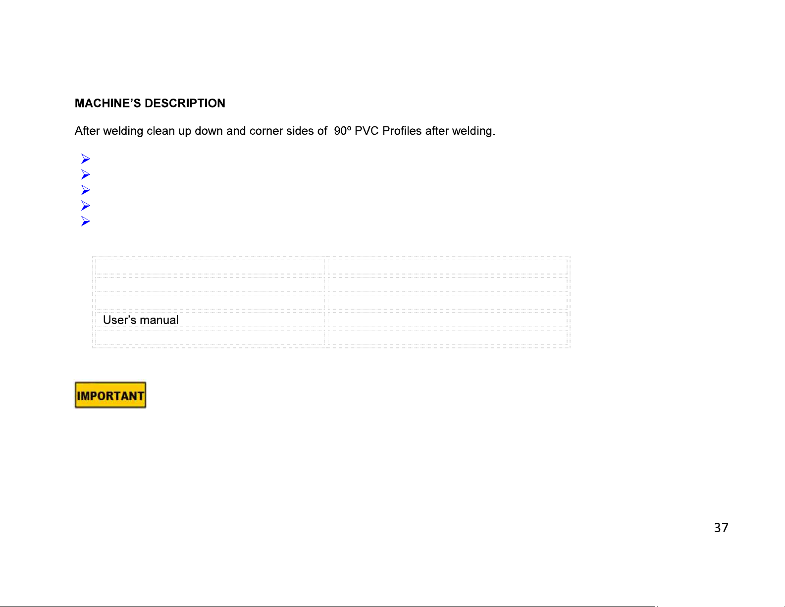
STANDAR
D A
CCESSORIES
OPTIONAL
ACCESSORIES
3.
Adjustable to different PVC profile types
Equipped with centralizing guide ensuring correct placement of profiles onto the set square.
Stops automatically after the corner cleaning operation.
Maximum profile processing height is 130 mm. (I165 mm profile processing height is provided as option)
PLC System, with serial change of blade groups.
Air Gun
Stand
4. TRANSPORT OF THE MACHINE
4.1. The transport should be done by qualified personnel only.
4.2. The machine should be transported by lifting with proper equipment (not touching the ground during the transport).
4.3. Unless customer requests the contrary, the machine will be delivered with wooden packaging.
4.4. Movable parts on the machine should be fixed before carrying out the transport.
4.5. The machine size and weight measurements, given the technical specification sheet.
Page 18

5. INSTALLATION OF THE MACHINE
5.1 Preparation
5.1.1 The machine size and weight measurements, given the technical specification sheet.The ground, where the
machine will be placed, should be even, solid enough to bear the weight of the machine
5.1.2 The machine should be located approx. 50 cm away from the rear wall
5.1.3 You can provide the balance of the machine with adjustable counterforts (PICTURE 2 NO 72) in the bottom
part.
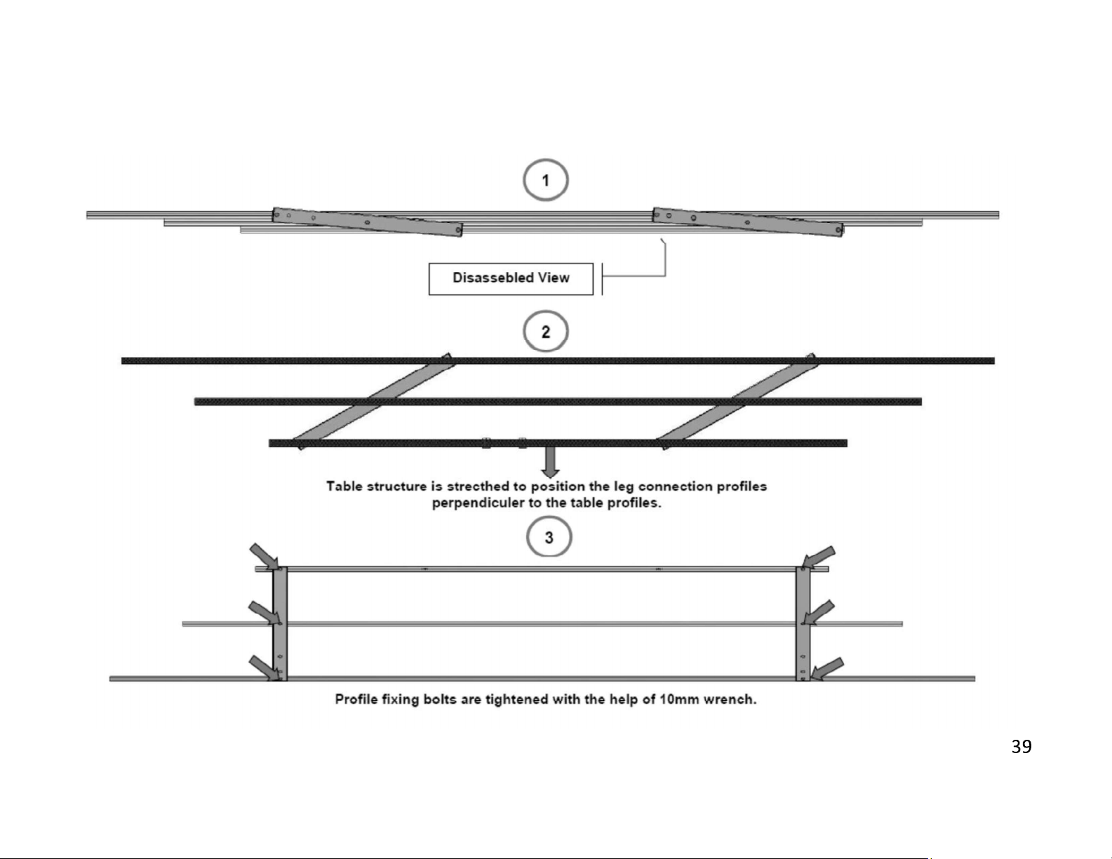
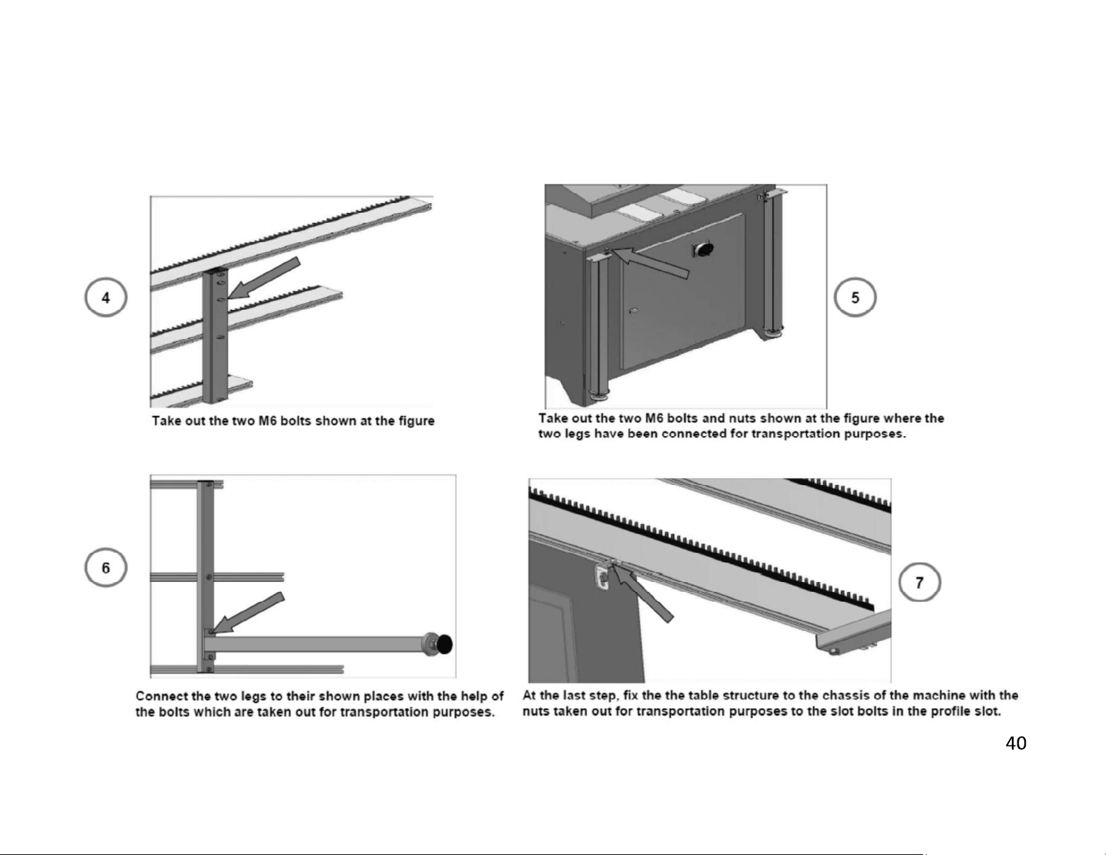
5.1.4 Tie the table of machine given as standard accessory on the front surface of the chassis. Apply the definition
below step by step for the assembly of the table.
Page 19
Page 20
Page 21
5.2 Connecting to Power Source
5.2.1 The Electrical connection must be made by a licensed electrician
5.2.2 The power outlet socket on the machine should be available.
5.2.3 Plug the machine to a grounded socket.
5.2.4 Main voltage of the machine is optional as 230 V 50 Hz or 400 V 50 Hz.
5.2.5 Check
type label
5.2.6 After electrical connection is made, machine must be operated in idle running and it must be controlled whether
rotation directions of cutting tools are correct or not and if the rotation direction is wrong, appropriate connection
must be made
6. MACHINE SAFETY INFORMATION
6.1 Lifting, installation, electric maintenance of the machine should be carried out by qualified personnel only.
6.2 Routine maintenance and scheduled maintenance should be carried out by qualified personnel after unplugging the
machine and disconnecting the air supply first.
6.3 Ensure that the machine has been cleaned, tested and maintain before starting to operate.
6.4
replaced defective safety devices or faulty parts.
Page 22
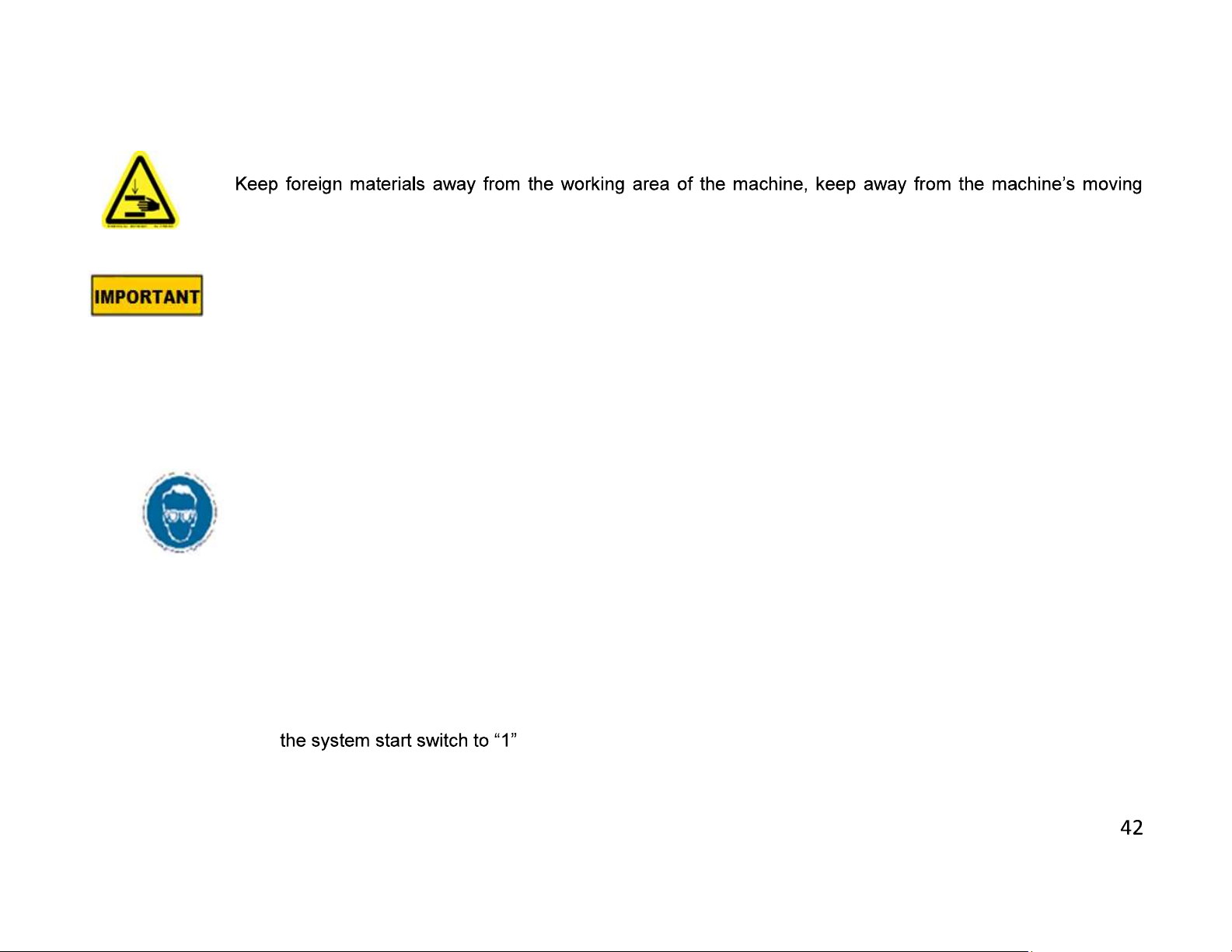
6.5 Never replace the milling cutters before unplugging first.
6.6
parts
6.7 Do not work on the machine by removing the protective parts
The safety data have been defined above. In order to prevent physical damage or damage to the
equipment, please read the safety information carefully and keep the manual always in an easy
accessible place.
7. OPERATION
7.1 Preparation
7.1.1 Degrease and dry the machine table. Especially ensure that the holding grips and handles are clean and dry
7.1.2 Clean all surfaces of the machine from chip and foreign particles. Use eye glasses for protection.
7.1.3 Control whether cutting tools (FIGURE 6 NO: 63) are inserted safely to their places.
7.1.4 Control cutting tools against corrosion, distortion and fractions. If cutting tools are damaged, change them.
7.1.5 Cutting tool must process on the part after machine is operated and cycled.
7.2 Operation
..
7.2.1 Switch
7.2.2 Select the necessary operation through the position selection button (FIGURE 3 NO.10).
Page 23

7.2.3 Put the boiled profile on the plate and justify it properly on the switches (PICTURE 4 NO.58) on set-square
(PICTURE 4 NO.26). Clamp will automatically fix the profile.
7.2.4 The machine will carry out the cleaning operation and stop.
NOTE: Press emergency button at the moment of potential danger
The milling cutters have to be started freely, without touching the profile. They have to start to
rotate first before making the milling operation.
8. MAINTENANCE, SERVICE AND REPAIR
8.1 Maintenance
8.1.1 Cut the electric and pneumatic power connections of the machine.
8.1.2 Clean all surfaces of the machine from burs, chips and foreign substances. If the machine will not be used for a
long time, lubricate undyed parts with oil that prevents rusting.
8.1.3 When cleaning the machine, do not use materials that may damage the dye.
8.1.4 Control cutting tools against corrosion, distortion and fractions. If cutting tools are damaged, change them..
8.1.5 Before using cutting tool, operate the machine out of gear and control whether it is inserted correctly, it is
without flexure and it is inserted appropriately. Do not use cutting tools that are damaged or lost its functionality.
8.1.6 If the sawteeth are blunted, change immediately with a new / sharpened saw.
8.1.7 Sharpen with proper sharpening machines by taking the angular value of the saw into consideration.,
Page 24
8.2 Changing the cutting tool
8.2.1 Use protective gloves when replacing Saw
8.2.2 Cut the electric connection of the machine.
8.2.3 Open the upper protection cover. (FIGURE 2-NO: 45)
8.2.4
WHEN REPLACING THE MILLING CUTTER GROUP, ENSURE THE CUTTERS ROTATE IN THE
CORRECT DIRECTION
Page 25
8.3 Adjust the air pressure (pneumatic systems)
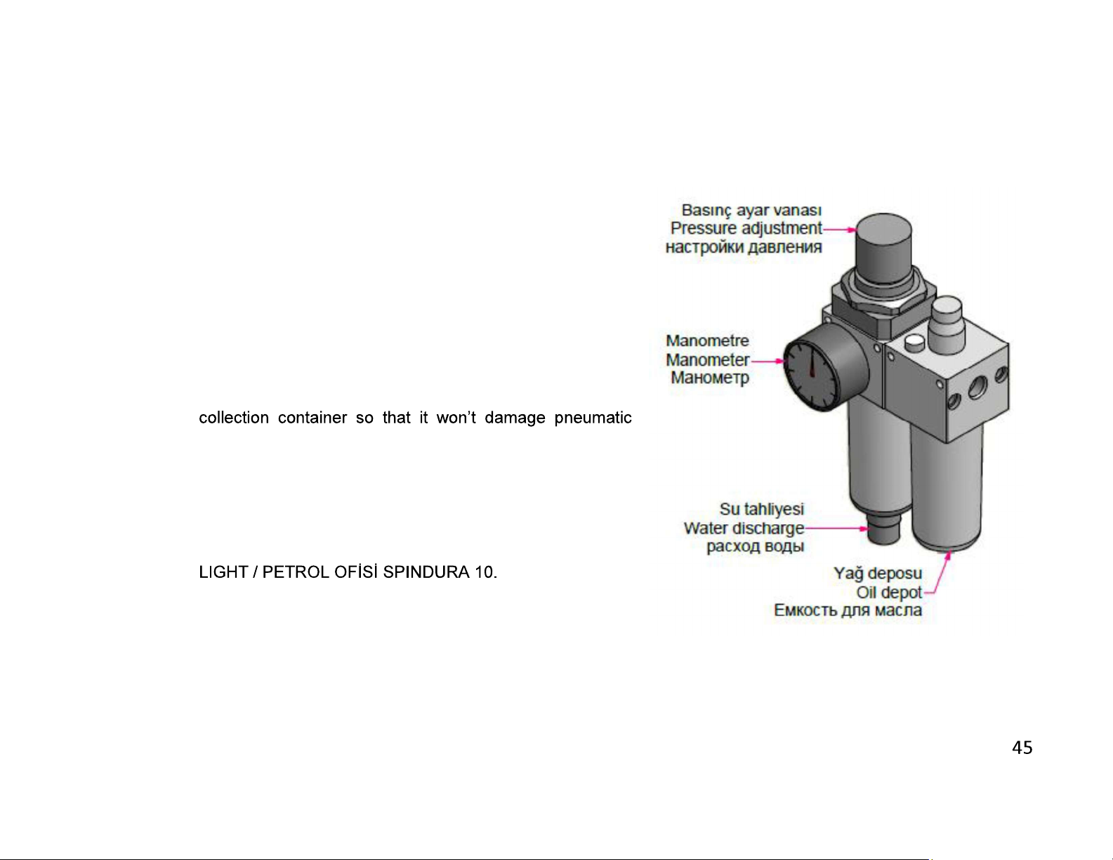
8.3.1 Pull up pressure adjustment valve. Set adjustment valve
to the desired value on manometer by turning it clockwise
or counter clockwise. Then lock the valve by pressing it
down.
8.3.2 Set the air pressure between 6 and 8 BAR. If air pressure
drops below the stated values, accessories operating with
pneumatic power do not work.
8.3.3 Conditioner unit accumulates the water in the air in the
components. At the end of the working day, empty the
accumulated water by opening water discharge valve
under the collection container
8.3.4 In order to put oil to the oil tank, remove the reservoir by
turning. Oils recommended by the manufacturer are; ;
TELLUS C10 / BP ENERGOL HLP 10 / MOBIL DTE
Page 26
Y1
Y2
Y3
Y1 Y2
Y3
9. TROUBLESHOOTING GUIDE
Here are some recommendations for solving urgent problems. If the trouble cannot be solved, or if you have a problem other
than those described hereunder, please contact our technical service or your nearest dealer.
FIGURE-7
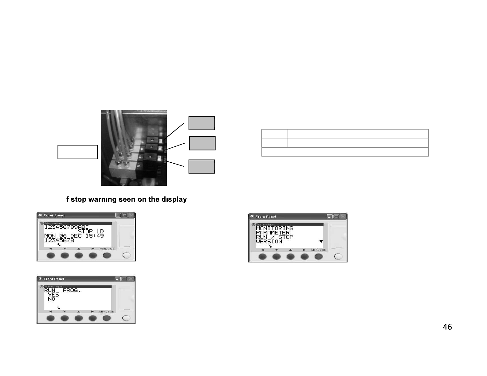
9.1. I
Press ok button the screen
below appears
Using up / down arrow buttons
point out yes command
pressing Menu / OK Button your
system passes the run mode.
Provide clamps movement
Provide scratching cutters movement .
Provide engine movement
Run prog.using up / down
arrow buttons, point out run /
stop and press Menu / OK
button.
Page 27
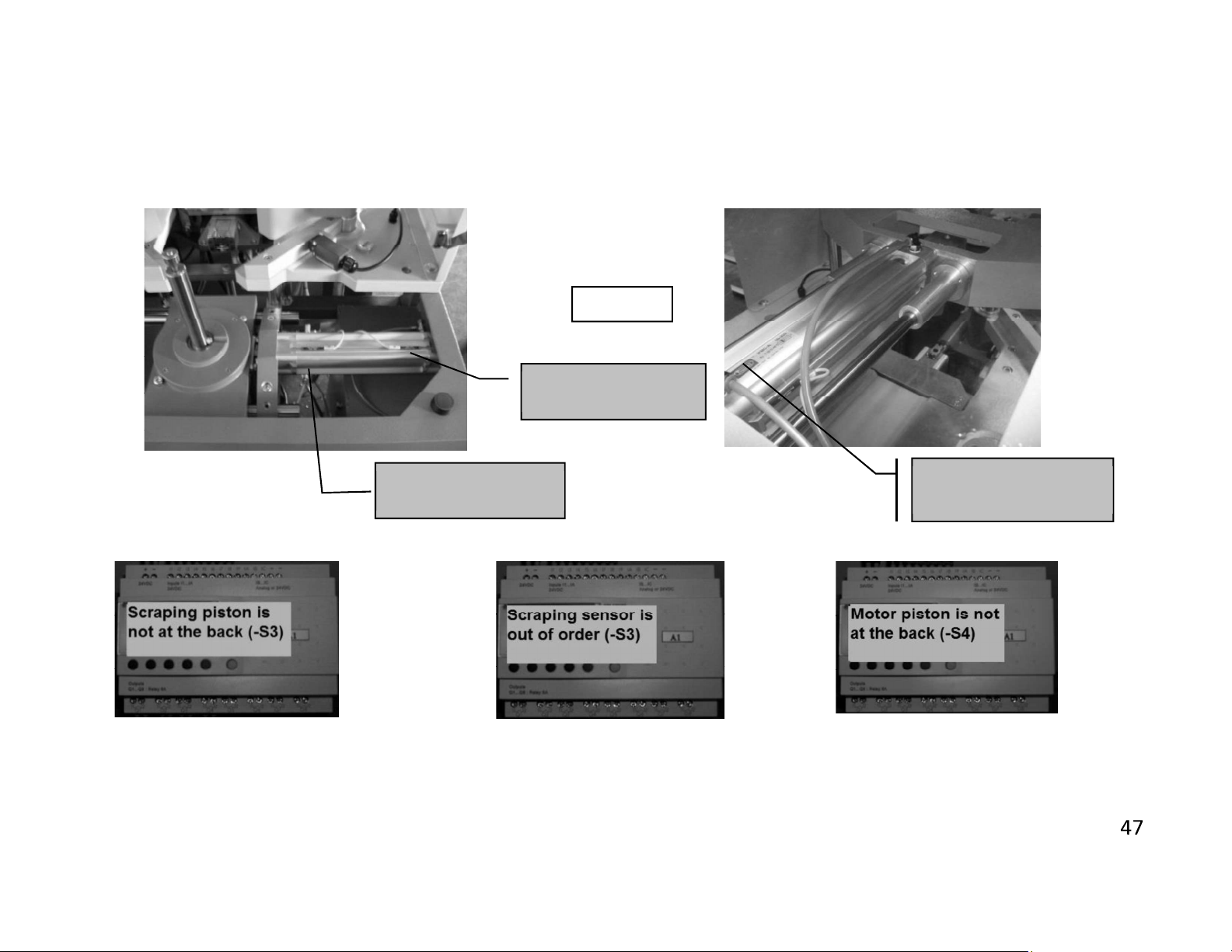
Ahead Sensor S7
at back Sensor S4
Scraping piston is not at the back
(-
S3)
;
Scraping sensor is out of order
Motor piston
not at the back (
-
S4) ;
9.2. Error notices on display
Insufficient air pressure or Y2 valve may
remain affixed
Motor Piston
FIGURE-9
Motor Piston
(-S3) ; Change S3 tearing piston
sensor
Top Tearing Piston
Sensor (-S3)
Insufficient air pressure or Y3 valve
may remain affixed
Page 28

Leaning switches are out of order (
-
S5
Leaning switches are out of order
Leaning switches are out of order
Change right set square
Emergency
stop (
-
S1) or the
cover is
Motor rear sensor is out of order
Motor forward sensor is out of
and S6) ; Change switches
open(-S8)
(LEFT) (-S5) ;
Change left set square switch
(-S4) ; Change the sensor
(LEFT) (-S6) ;
order (-S7); Change the sensor
Page 29
10. WARRANTY CONDITIONS
YILMAZ Machine Industry and Trade Limited Company, guarantees that all machines have been tested and
conform to the international standards.
The guarantee is valid 24 months from despatch date and does not cover the electrical parts of the machine.
During this period:
- Any repair and replacement effected at our workshop is completely free of charge (only transport costs are at
e).
-
lodging costs for our technician.
The guarantee does not cover damages caused by:
- not respect of the rules indicated in the manual instruction book
- not correct voltage
- improper use or use not in accordance with what the Machine has been designed for
- use of non original tooling
- programming errors
- lack of cleaning and of ordinary maintenance by the customer
- transport or displacement (even inside the workshop)
- natural events (lightings, fires, floods)
The warranty does not cover, in any case, damages caused by the malfunction of the Machine
Page 30
ELECTRIC&PNEUMATIC
Page 31
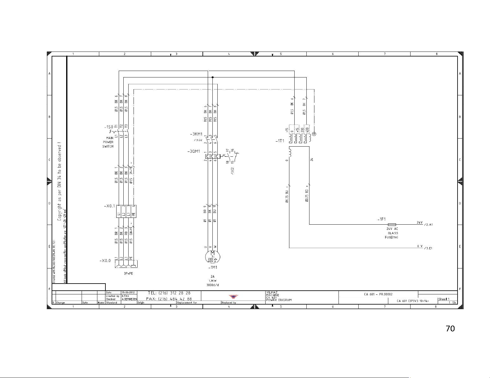
3 PHASE ELECTRICAL DIAGRAM SHEET 1
Page 32
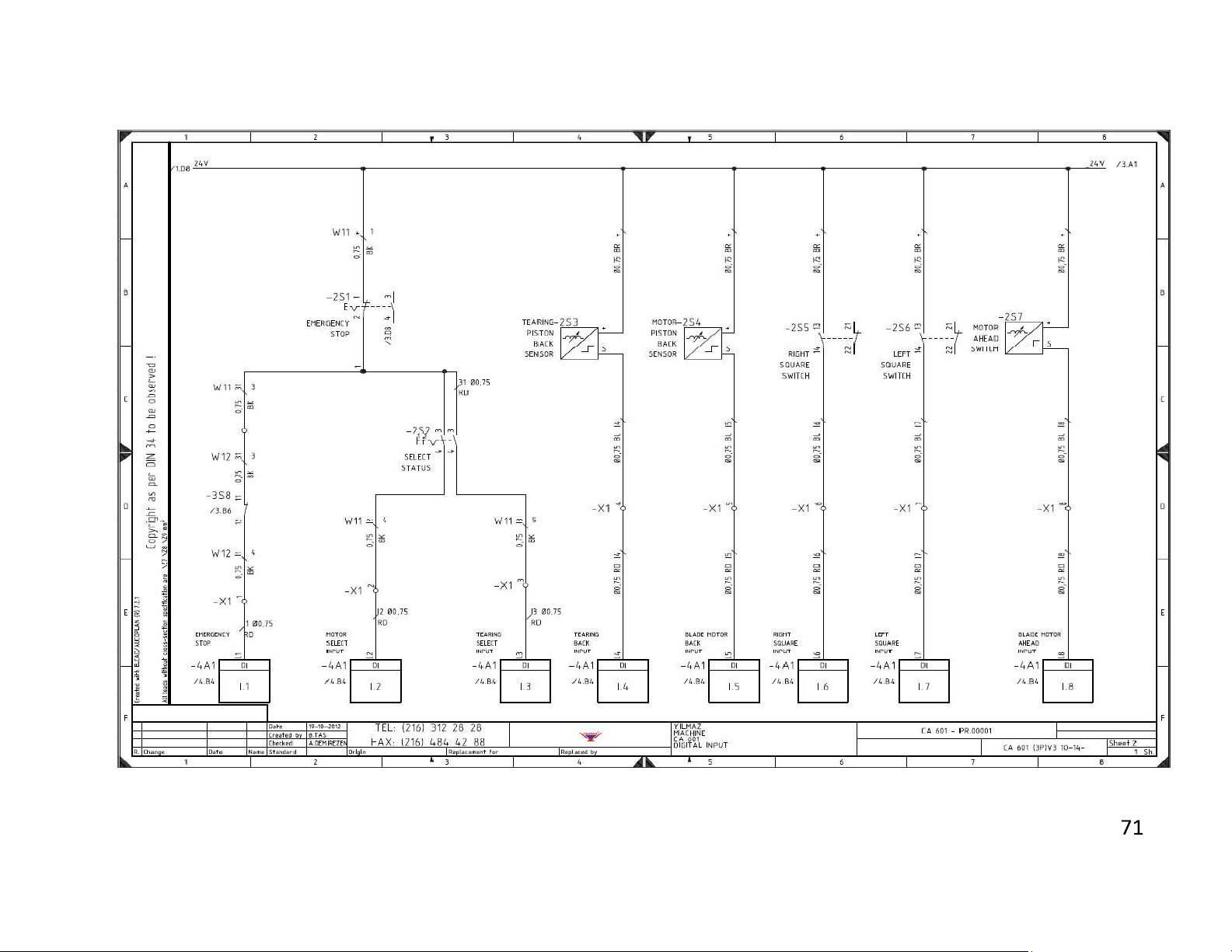
3 PHASE ELECTRICAL DIAGRAM SHEET 2
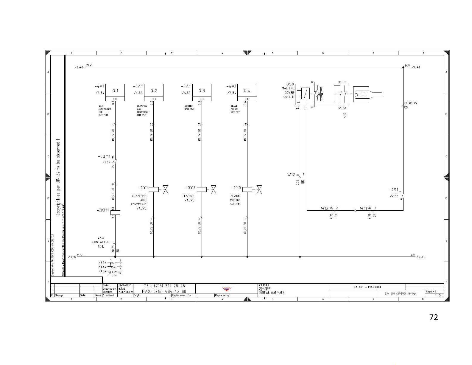
3 PHASE ELECTRICAL DIAGRAM SHEET 3
Page 33
Page 34
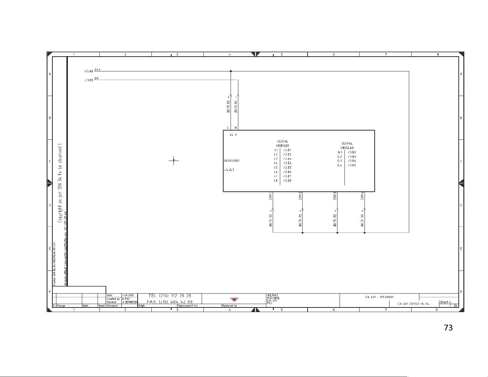
3 PHASE ELECTRICAL DIAGRAM SHEET 4
Page 35
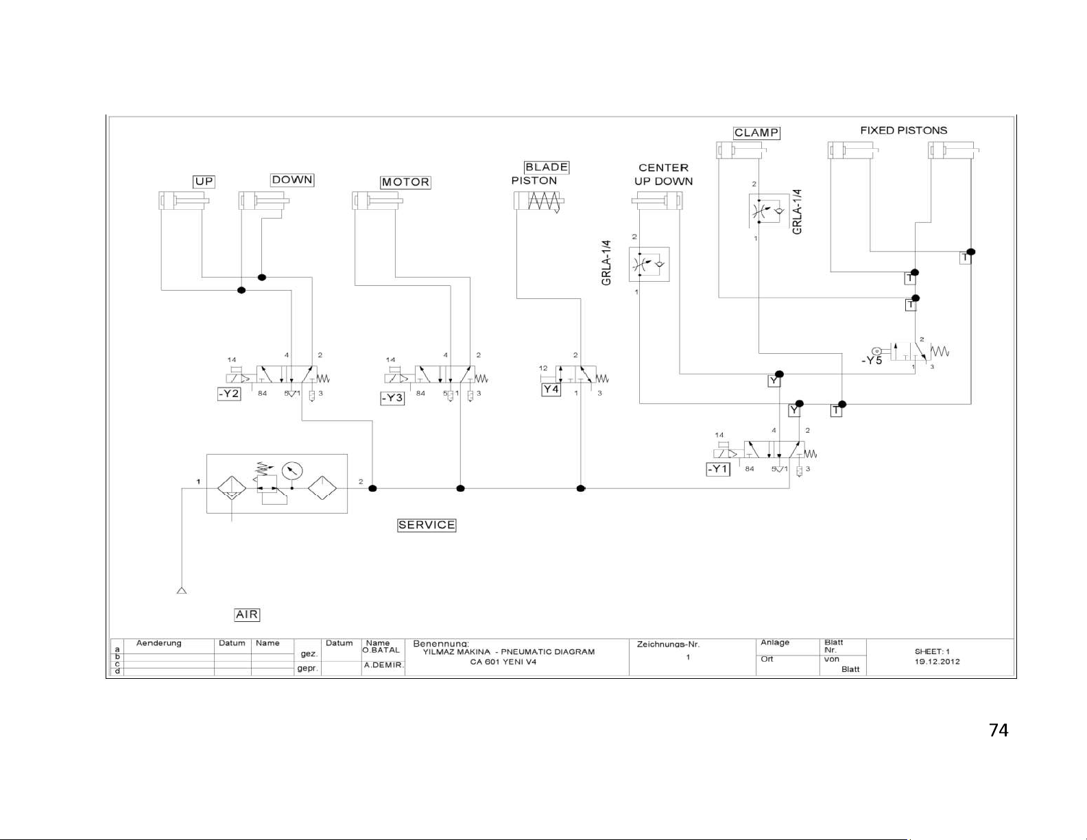
PNEUMATIC DIAGRAM SHEET 1
 Loading...