

Page 1
单相
直流电源
操作和维
护手册
YIBO
TECHNOLOGIES
YIBO
技术
中国 上海市
嘉定区华江路1078号2单元
电话:86-21-52656378,传真:86-21-59143403
IP-LX
DC POWER
CONTROLLE
Operation
SHENGNENG TECHNOLOGIES
10 Technology Drive
Lowell, Massachusetts 01851
tel: 86-21-52656378 • ´«Õæ: 86-21-52656378*84
&
Maintenance
Manual
IP-LX400PWRMAN
REV JUNE 2003
Manual Covers:
IP-400VPCB
Page 2

DC POWER CONTROLLER – IP- 400VPCB
注意和警告信息
警告和注意标签是用于对手册中基本和危险的信号提醒注意。标签将显示与它们有关的信息。
表示避免个人伤亡的条件、经验、和方法。
表示可能会引起伤害和设备故障或者长期工作会危害健康的环境。
概述
IP400VPCB是专为IONPURE制造的持续电离模块而特别设计的。这些模块在本手册中称为“LX模
块”。
该电源是通过可控硅桥的相位角控制来实现把单项交流电转变成脉动的直流电。最大直流输出为
400v直流,交流输入440V,交流的输入必须通过变压器进行隔离。
最大电流输出可选择2.5,4,6.5和10。“电流反馈回路”控制电流使其不受外部负载的影响。
电源能以衡压或衡流模式进行控制。在衡压模式下,输出电压将维持在操作者设定的数值上,除非
电流超过极限值。如果负载阻值减少很多造成电流超过极限值,那么电压将自动降低,使其回到极
限值内。
在衡流模式下,输出电流不受负载电阻变化的影响将自动保持在设定数值上,除非电压需要超过交
流电源电压的90%。电压限定在最大数值,如果外部负载继续增大,输出电流将会减小。
CAUTION AND WARNING MESSAGES
5ARNING and CAUTION labels are used to attract attention to essential or critical information in this manual. The
labels will appear next to the messages associated with them.
Warnings indicate condition, practices, or procedures that must be observed to avoid
personal injury or fatalities.
Cautions indicate a situation that may cause damage or destruction of equipment or may
pose a long-term health hazard.
GENERAL DESCRIPTION
T6 6666 DC power controller IP400VPCB was designed specifically to provide DC power to continu
electrodeionization modules manufactured by Ionpure Technologies. These modules will be referred to as “LX
modules” in this manual.
his 4er controller util44s a phase-angle fired SCR bridge to produce a variable DC output from a single-phase
AC input. Maximum DC output voltage is 200, 300 or 400 VDC, corresponding to an AC input voltage of 220, 330,
or 440 VAC, respectively. The AC input must be isolated from the AC mains by an isolation transformer.
The maximum DC output current can be jumper selected at 2.5, 4, 6.5 or 10 amperes. A “current fold back”
control circuit limits the maximum current to these values regardless of load resistance.
The controller can be operated in either constant voltage or constant current mode. In constant voltage mode, the
DC output voltage will be maintained constant at the value selected by the operator, except in cases where the
current limit is reached. If the load resistance decreases sufficiently so that the current reaches the current limit,
the voltage will be reduced automatically to maintain the current at the limit.
In the constant current mode, the output current will be maintained constant at the selected value, regardless of
the load resistance, except in cases where the voltage required reaches the maximum DC voltage possible (90% of
the RMS AC input voltage). The voltage would then be limited to the maximum value, and if the resistance
continues to increase, the output current will decrease.
2 IP-LX400PWRMAN REV -
Page 3
DC POWER CONTROLLER – IP- 400VPCB
直流输出电压和电流能通过下列方法调节
型号IPDISP1,能控制和显示一块电源的输出。
型号IPDISP8,能控制和显示八块电源的输出。
外部输入的0-5v的直流信号,如PLC。
电源的输出能用继电器控制其通断。如水流开关。对应0-5v输出的电压和电流可以用外部的电压和
电流表显示。
电源包含一块线路板和安装铝板。
The DC output voltage or current can be adjusted by the following methods:
• An optional display board, Part No. IP DISP1, which can control and display the DC output from one power
controller.
• An optional display board, Part No. IP DISP8, which can control and display the DC outputs from up to eight
power controllers.
• A 0 - 5 VDC input signal from a remote process controller, such as a PLC.
The power controller output can be turned on and off by a remote set of contacts, such as in a flow switch. 0-5
VDC output signals corresponding to the output voltage and current are available for a remote voltmeter and
ammeter to indicate the output voltage and current.
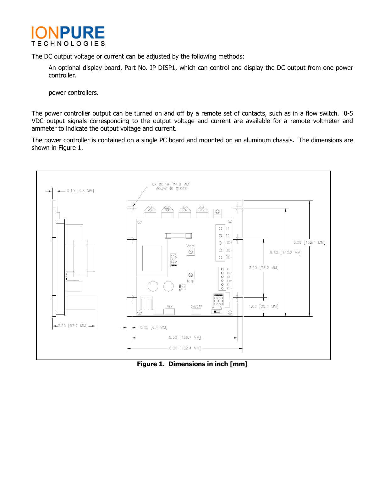
The power controller is contained on a single PC board and mounted on an aluminum chassis. The dimensions are
shown in Figure 1.
Figure 1. Dimensions in inch [mm]
3 IP-LX400PWRMAN REV -
Page 4

电源安装在箱体内的一块附加的板上,它用至少四个M4或UNC8-32 螺丝固定。
安装孔位置如图一所示。
装置采用空气对流冷却,必须安装在空气能够对流的地方。
环境温度0-50摄氏度,湿度为90%(无冷凝)。
箱体推荐至少达到IP52等级。
箱体需安装风扇,使周围空气能与箱体对流。防水箱体需达到IP56等级。
箱体内部的冷却非常困难。一般冷却方法包括:
增加箱体尺寸,使得热量能够通过箱壁散热。
风冷或水冷。
降低空气温度。
每块电源产生的热量约为40W,另外变压器和箱体内的其它部件也会产生一定的热量。
安装
电源
典型安装的元件图见图二。
变压器
直流电源的交流输入必须用变压器进行隔离,这个变压器的容量应能满足电源的需求,变压
器的作用是:
将交流电源隔离,直流的输出负极就能接地。
能将交流电源转换成电源或模块需要的电源,变压器见图二,例如,能够将220AC转换
成440VAC输入到电源。
变压器的次级不要接地,否则会损坏电源。
请看附录A中变压器推荐接法。
过电流保护
电源的输入端没有设计交流电源过电流保护,如短路器或保险丝。所以必须在
变压器和交流输入的初级装上这些装置,见图二。
INSTALLATION
1. Mounting
The DC power controller is to be mounted on a sub-panel inside an enclosure with at least four screws,
either M4 or UNC 8-32. The location of the mounting slots is shown in Figure 1.
The unit is cooled by convection, and must be located where there is no interference with air circulation.
The environmental limits for operation are 0 °C to 50 °C at up to 90% relative humidity (non-condensing).
An enclosure with at least an IP52/NEMA 12 rating is recommended. The enclosure should include a
cooling fan that draws ambient air through the enclosure.
In installations where a water resistant enclosure (IP56/NEMA 4) is necessary, cooling the interior of the
enclosure is more difficult. Typical cooling methods include:
• Sizing the enclosure for sufficient rate of heat transfer to the environment through the enclosure
walls
• Air-to-air or water-to-air heat exchanger
• Air conditioning
DC POWER CONTROLLER – IP- 400VPCB
The maximum heat generated by each power controller is approximately 40 watt. Additional heat
generation is expected from the isolation transformer and other equipment in the enclosure.
2. AC Supply
An electrical schematic for a typical installation is shown in Figure 2.
2.1 Isolation transformer
The AC input to the DC power controller must be isolated from the AC mains by an isolation transformer
that is correctly sized for the maximum power required from the power controller. The purpose of the
transformer is to:
• Isolate the AC input to the power controller from the AC mains so that the DC negative output can
be grounded.
• Convert the voltage of the AC mains to an AC input voltage for optimum operation of the power
controller and the LX module. The transformer shown in Figure 2, for example, can convert the 220
VAC from AC mains to either a 220 VAC or 330 VAC input to the power controller.
The secondary of the transformer must NOT be connected to earth ground. Grounding
the secondary and the DC negative will damage the power controller.
Please see Appendix A for recommended designs for the isolation transformers.
2.2 Overcurrent protection
The power controller does not have built-in fuses for the AC input. Overcurrent
protection devices, such as circuit breakers or fuses, must be installed between the
isolation transformer and the AC input terminals, as shown in Figure 2
4 IP-LX400PWRMAN REV -
Page 5

DC POWER CONTROLLER – IP- 400VPCB
直流的最大输出为10A,所以大多数系统都推荐20A的过电流保护装置。
变压器的次级也要装过电流保护装置,容量按照需要选择。
高压连接
交流电源的选择
用LX性能测试程序(IP-PRO2003)来估计每个模块所需的直流电压和电流,测量指标包括水
的流量,成分和温度。
选择能满足电源需要的变压器次级线圈的最低档。注意直流电压的最大值约为次级交流电压
的90%。
例如:
440V
Since the maximum DC output current is limited to 10 A, a current rating of up to 20 A for the overcurrent
protection devices is recommended for most installations.
Overcurrent protection devices must also be installed on the primary of the isolation transformer and sized
correctly according to applicable local electrical codes.
Figure 2. Electrical schematic of a typical installation
3. High Voltage Connections
3.1 initial selection of AC input voltage
Use the LX Performance Projection Program (IP-PRO2003) to estimate the DC voltage and current
requirement per LX module, which depend on the feed water flow rate, composition and temperature.
Select the secondary winding on the isolation transformer with the lowest voltage that would still result in
a maximum DC voltage above the required value. Note that the maximum DC voltage is approximately
90% of the secondary AC voltage.
For example:
5 IP-LX400PWRMAN REV -
Page 6

DC POWER CONTROLLER – IP- 400VPCB
假设如图二IP-LXM24H-3模块装有5KVA的变压器,直流电压通过测试需要375VDC。
次级线圈440VAC会产生400VDC ,所以我们选择440VAC。
将线接在变压器次级的440VAC一档,这样440VAC就供给电源了。
440VAC
Assuming that a 5 kVA isolation transformer as shown in Figure 2 is installed for an IP-LXM24H-3 module,
and the DC voltage calculated by the LX Performance Projection Program is 175 VDC.
The secondary winding for 220 VAC will result in a maximum DC output of 200 VDC and the secondary
winding for 330 VAC will result in a maximum DC output of 300 VDC. Select the 220 VAC winding.
Wire the secondary of the transformer for 220 VAC, which will be the voltage of the AC input to the power
controller.
iring connections and jumper locations on IP400VPCB
Figure 3. Wiring connections and jumper locations on IP400VPCB
6 IP-LX400PWRMAN REV -
Page 7

DC POWER CONTROLLER – IP-400VPCB
高压连接
交流和直流按下表连接(见图三)
正极
负极
接地
进线
输入
端子
电源到模块连接盒的接线请看LX模块操作和保养说明书。
直流阴极输出必须接地。DC负极的第二个端子用于连接电源箱中的保护电路
跳线和选择开关
跳线选择交流输入电压
无
选择交流电源频率的跳线
频率跳线是调节内部的控制波形,应该和输入的交流电源频率一致。
电流限制跳线
电流限制跳线有四个定位,对应2.5,4 ,6.5 和10安培。
对于LX模块除非手册上另有说明,否则跳线应设置在10A一档。
拨动开关选择控制模式
拨动开关
控制模式
衡压模式
衡流模式
LX模块推荐用衡流模式。
低压连接
直流输出控制
使用下列其中之一的方法:
3.2 High voltage connections
AC and DC power connections must be made as follows (see Figure 3):
Connection Terminal
AC input T1 and T2
DC positive output DC+
DC negative output DC-
Ground DC-
Please see the Operation and Maintenance Manual for the LX module for details on the terminals inside
the junction boxes on the module.
The DC negative output must be grounded. A second DC- terminal is provided on the
power controller for connection to the protective bonding circuit (Ground circuit) inside the
power supply enclosure.
4. Jumpers and Selector Switches
4.1 Jumper for selection of AC input voltage
The jumper for the AC input voltage (see Figure 3) must be placed in the position
corresponding to the voltage of the AC input from the isolation transformer. Failure to do
so will result in failure of the unit.
4.2 Jumper for selection of AC frequency
The frequency select jumper adjusts an internal control waveform, and must be set to the frequency of the
AC input.
4.3 Jumper for current limit
The current limit jumper can be placed in one of four positions, corresponding to 2.5, 4, 6.5, and 10
amperes current limit.
For LX modules, set the limit at 10A unless otherwise instructed by the Operation Manual for the LX
system.
4.4 Slide switch for selection of control mode
Slide position Control mode
V
A
Constant voltage mode
Constant current mode
Constant current mode is recommended for operation of LX modules.
5. Low Voltage Connections
5.1 Control of DC output.
Use only one of the following options:
7 IP-LX400PWRMAN REV -
Page 8

DC POWER CONTROLLER – IP- 400VPCB
在箱体的面板上安装一块型号为IP DISP1的单显示板。
这块板能够控制和显示一块电源的电压。
看显示板的安装手册。连接线一头插在显示板上另一头插在电源上。
输出电压和电流具体看控制模式,调节是用显示板上旋钮。
在箱体面板上安装一块型号为IP DISP8的八路显示板。
这块显示板最多能够控制和显示八路电源,用于多模块且要分别控制电源的系统中。
具体看显示板的安装手册。灰排线的一端插在电源板上,另一头插在显示板上(见图
三)。
输出电压和电流具体看控制模式,调节是用显示板上旋钮。
用0-5VDC的隔离信号来控制直流输出。控制信号的连接如下所示(见图三):
信号正极
信号负极
在衡压控制模式下,0-5VDC控制0-100% 的最大直流输出电压。
在衡流控制模式下,0-5VDC控制0-100% 的最大直流输出电流。
外部控制通断
直流输出能被外部无电源继电器(无水流继电器)控制,连接到表有“ON/OFF”的接线端
(见图三)。 继电器闭合电源工作;继电器断开电源停止。如果装有显示板当电源停止时
黄色的“STANDBY”或“DISABLED”指示灯点亮。
在典型安装中,“ON/OFF”端连接一个或多个水流继电器(见图三),当没有水流时,系
统或模块全部或个别缺水时防止电源送电。
这个操作交流电源没有切断,要想切断需要在变压器的次级加装短路器。
在典型安装里,只有当水流流过LX模块时继电器线圈才会动作使得继电器闭合。
信号输出
一对0-5VDC隔离输出信号是留给外部显示的。该信号为每10mv对应直流输出为1v。
如果需要将下列端子接外部电压表或显示(见图三):
Vout 信号正极
COM 信号负极
这些信号是由运放产生,请不要将其和电源连接或和小于10K OHM的电阻连接。
另一队隔离输出 0-5VDC信号是留给外部电流显示用的,该信号对应0-100%的电流设定
值。
需要时将下列端子接到外部电流表或显示。
Iout 信号正极
COM 信号负极
• Install the single-channel display board, Part No. IP DISP1, on the door of the enclosure. This board
can control and display the DC output from one power controller. See instructions for the display
board for mounting instructions. Plug one end of the control cable (ribbon cable) into the socket on
the DC power controller header (see Figure 3). Plug the other end into the display board. The
output voltage or current, depending on the control mode selected, is adjusted by a potentiometer on
the display board.
• Install the eight-channel display board, Part No. IP DISP8, on the door of the enclosure. This board
can control and display the DC outputs from up to eight power controllers and is used in systems
with multiple LX modules with individual power controller for each module. See instructions for the
display board for mounting instructions. Plug one end of the control cable (ribbon cable) into the
socket on the DC power controller header (see Figure 3). Plug the other end into the display board.
The output voltage or current, depending on the control mode selected, is adjusted by a keypad on
the display board.
• Use a 0-5 VDC isolated signal from a remote source (a PLC, for example) to control the DC output.
Connect the control signal as follows (see Figure 3):
Ctrl Signal positive
COM Signal negative
In the voltage control mode, the 0-5 VDC corresponds to 0-100% of maximum DC voltage.
In the current control mode, the 0-5 VDC corresponds to 0-100% of the current limit.
5.2 Remote ON/OFF
The DC output could be switched on/off by a remote isolated non-powered contact (dry contact), connected
to the plug-in terminals labeled “ON/OFF” (see Figure 3). A closed contact allows the DC power controller
to operate; an open contact disables the controller. If a display board is installed, the yellow “STANDBY” or
“DISABLED” light on the board will be lit when the controller is disabled.
In typical installations, the “ON/OFF” terminals are connected to one or more flow switches on the feed,
product and/or reject streams on the LX module or system to prevent DC power from being applied to the
module when there is no water flow. The switches must be wired in series if more than one flow switch is
installed.
This control does not shut off AC power to the unit. To remove AC power, a
contactor is required on the primary of the isolation transformer, as shown in Figure 2.
In typical installations, the coil of the contactor is wired so that the contactor is closed only when there is
feed water flow to the LX module(s).
5.3 Analog outputs
• A 0-5 VDC optically isolated output signal pair is provided for remote display of output voltage. The
signal is calibrated to 10 mV = 1 V of DC output.
Connect the following terminals to a remote voltmeter or display if required (see Figure 3):
Vout Signal positive
COM Signal negative
These signals are developed by operational amplifiers, and must not be connected to power sources
or drive load resistance less than 10 KΩ.
8 IP-LX400PWRMAN REV -
• A 0-5 VDC optically isolated output signal pair for remote display of output current. The signal is
calibrated to 0-5 VDC corresponding to 0-100% of the current limit.
Connect the following terminals to a remote ammeter or display if required (see Figure 2):
Iout Signal positive
COM Signal negative
Page 9

DC POWER CONTROLLER – IP- 400VPCB
这些信号是由运放产生,请不要将其和电源连接或和小于10K OHM的电阻连接。
操作
启动
启动顺序根据系统的设计而定。请参考操作手册。
启动顺序举例
下面的操作顺序只是根据图二所示典型单模块系统举的一个例子。
闭合断开的开关或短路器。显示板上的指示灯将会点亮。“AMP”指示灯也点亮。输出
电流显示为默认状态。
如果没有水流过模块水流开关为断开,那么显示板上的“STANDBY”的灯将会点亮。
如果显示板上有调节电压的按钮,先将其调到最小(零输出)。
打开适当的电压进行设备预处理。如系统反渗透。
调节流过模块的淡水和浓水的流量。当水流开关闭合,显示板上绿色的“ON”指示灯
点亮。
慢慢将电流调到通过LX程序测定出来的数值。对于用电位器调节的显示板,将电位器向
右转,对于用按键控制的显示板,则是用“UP”“DOWN”来操作。如果选择了衡流
模式如果控制电流的电压还未超过最大直流输出电压,那么电源将会自动把电流维持在
设定值上。
按下标有“PUSH TO DISPLAY VOLTAGE”的按钮,来读取直流输出电压。此时绿色的
“VOLT"的指示灯将会点亮。
通过这些正规的操作,不需要进一步的注意电源。如果水流开关断开,电源将会停止,显示
板上黄色的“STANDBY”的灯将会点亮。可能会发生这种情形,例如,检测水流的开关偶
然闭合。那么可以在反渗透电路和断路器之间加个连锁,如果反渗透电路关闭,那么将电源
也切断。
输出调整
如果水流的条件发生变化,如水的流量,成份和温度,那么直流输出需要进行调整。
变压器次级电压的变化
变压器次级电压变化的原因
在一般情况下,LX模块的阻值会随着水的成分和温度的变化而变化。
水的温度变低会增加模块的阻值。
These signals are developed by operational amplifiers, and must not be connected to power sources
or drive load resistance less than 10 KΩ.
OPERATION
1. Initial Startup
The startup sequence depends on the design of the LX system. Please consult the Operation Manual for
the LX system.
1.1 Example of startup procedure
The following startup procedure is only an example for a typical single module LX system with electrical
schematic as shown in Figure 2.
• Close the main disconnect switch (or circuit breaker) for the LX system. The LED display on the
display board must be lit. The green “AMP” light next to the display must be lit. The output current is
displayed by default.
• The yellow “STANDBY” light on the display board must be lit if there is no flow through the module
and the flow switch is open.
• If the display board has a potentiometer for adjusting the power controller output, turn the
potentiometer to fully counter-clockwise position (zero output).
• Open the appropriate valves and start the pretreatment equipment, such as the reverse osmosis
(RO) system, ahead of the LX system.
• Adjust the flow rates of the dilute and concentrate streams through the module. The green “ON” light
is on the display board must be lit once the flow switch is closed.
• Slowly increase the DC output current to the value calculated by the LX Performance Projection
Program. For a display board with potentiometer, turn the potentiometer clockwise. For a display
board with keypad control, use the “UP” and “DOWN” buttons. The power controller will maintain the
current at that setting if the current control mode is selected and if the required voltage to drive the
current is lower than the maximum DC voltage available.
• Push the switch labeled “PUSH TO DISPLAY VOLTAGE” to read the DC output voltage. The green
“VOLT” light next to the display must be lit.
During normal operation, no further attention to the DC power controller is necessary. The DC output will
be turned off if the flow switch opens, and the yellow “STANDBY” light on the display board will be lit. This
situation may occur, for example, if the flow monitored by the flow switch is shut off accidentally. If there is
an interlock between the RO process controller and the contactor ahead of the isolation transformer, the
contactor will open if the RO system shuts down.
2. Output Adjustment
The DC output current may need to be adjusted if there is a change in feed water conditions such as flow
rate, composition and/or temperature.
3. Change in Transformer Secondary Voltage
3.1 Reasons for changing transformer secondary voltage
Under normal operating conditions, the electrical resistance of the LX module may vary depending on the
composition and temperature of the feed water. A lower feed water temperature would increase the
module resistance, for example. The module resistance, however, may also increase if the module is
fouled by organic matter or scaled.
9 IP-LX400PWRMAN REV -
 Loading...