

Page 1

2987 NH3 MAGNUM
2565-758_REV_I • 04/2014
YETTER MANUFACTURING CO.
FOUNDED 1930
Colchester, IL 62326-0358
Toll free: 800/447-5777
309/776-3222 (Fax)
Website: www.yetterco.com
E-mail: info@yetterco.com
Page 2
2 3 4
Page 3
Page 4
Page 5

5
Page 6
6
Page 7
ASSEMBLY INSTRUCTIONS
The 2987 NH3 Magnum coulter is designed to mount to rectangular toolbars in three sizes: 5” x
7”, 6” x 6”or 7” x 7”.
WARNING:
lockups.
WARNING:
The Avenger coulter can be mounted to the toolbar using different techniques. One way is to
mount the main arm assembly to the toolbar and then attach the components one at a time.
Another way is to completely assemble the avenger coulter before attaching to the toolbar frame.
NOTE: To aid the assembly of the opener, it is recommended that a stand be constructed to
temporarily attach the opener and hold it in an upright position.
CAUTION:
attention to lifting techniques while handling and or maneuvering the coulter during assembly is
very important. Failure to do so may lead to personal injury or death.
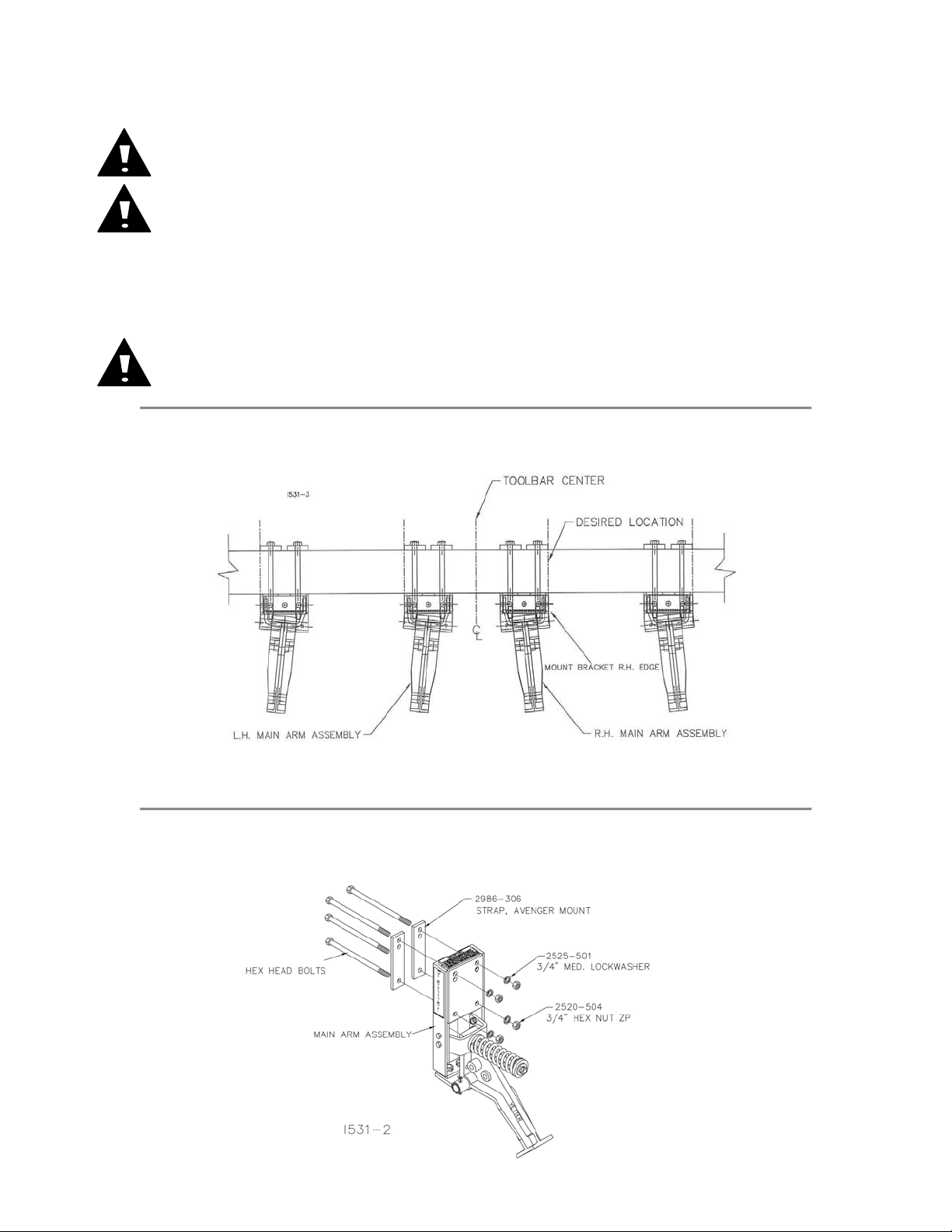
STEP 1. Mark the toolbar frame as to the location that each coulter is to be mounted.
Right hand assemblies are usually mounted on the right hand side of the toolbar and the left hand
assemblies are mounted on the left hand side of the toolbar.
Never work under the toolbar while in a raised position without using safety
Use extreme caution, the blade is sharp and may cause bodily injury.
The 2987 NH3 Magnum coulter and its components are very heavy. Extra
NOTE: The coulter blade is in line with the edge of the mount bracket, for a reference use the
edge of the mounting bracket (right hand edge for a right hand and left hand edge for a left hand)
to align with the mark on the toolbar so that the coulters are mounted at the desired spacing.
STEP 2. Attach the main arm assembly to the toolbar using 2) 2986-306 mounting straps,
4) hex head bolts, ¾” lock washers and ¾” hex nuts.
7
Page 8
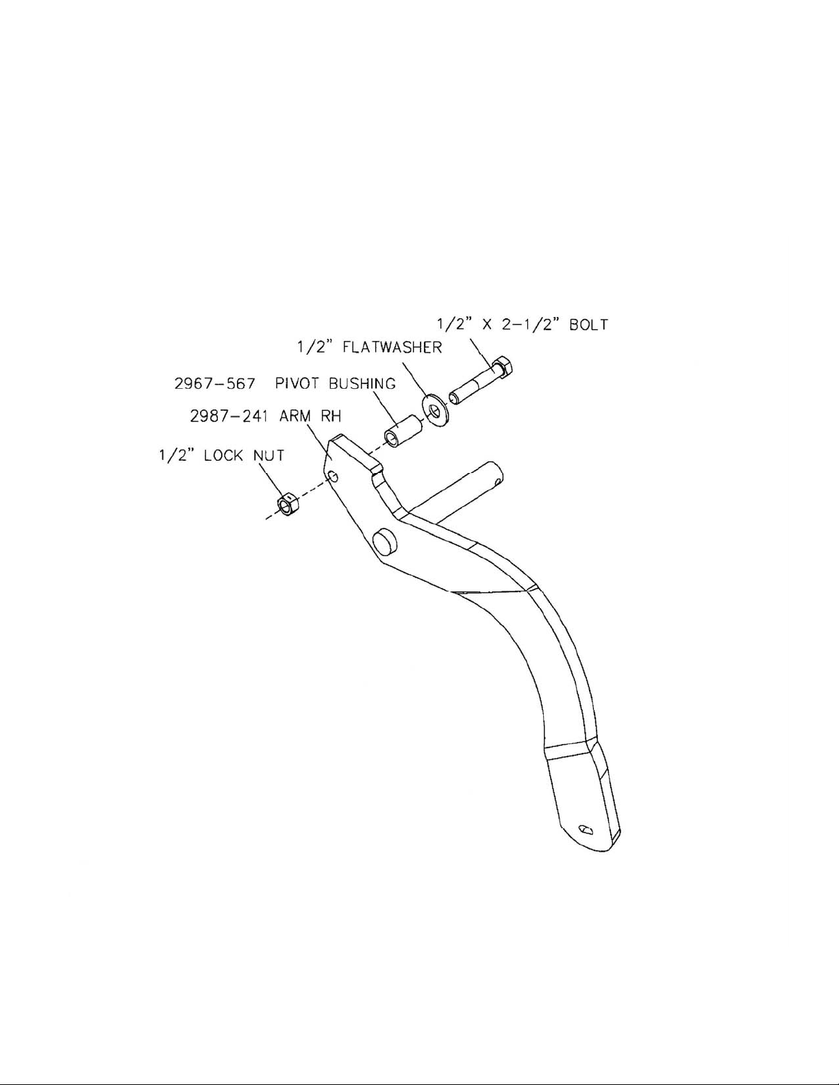
ASSEMBLY INSTRUCTIONS
Step 1. Install the ½” x 2 ½” bolt, washer, bushing and lock
nut to the closing wheel arm.
I800-001-SEALER
8
Page 9
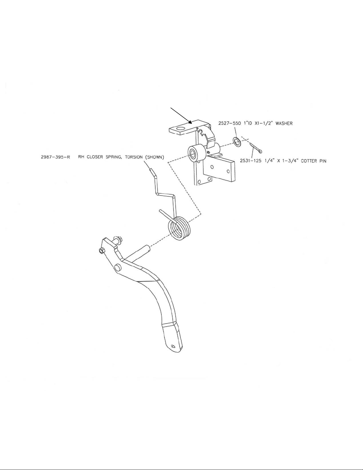
ASSEMBLY INSTRUCTIONS
Step 2. Attach the closing wheel arm and the torsion spring
to the knife mount, install the cotter pin and washer.
KNIFE MOUNT
I800-002-SEALER
9
Page 10
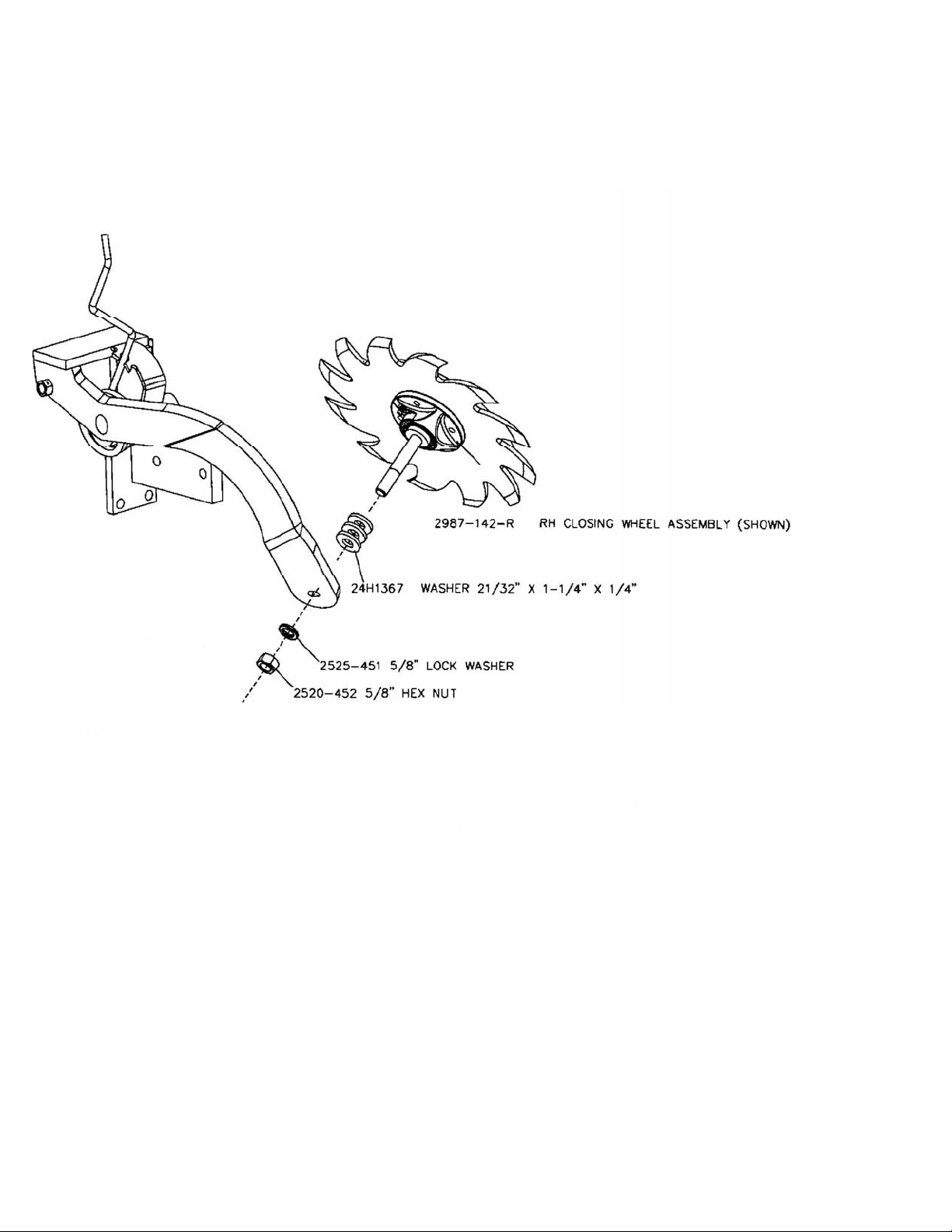
ASSEMBLY INSTRUCTIONS
Step 3. Attach the closing wheel assembly to the arm, use 3
washers, lock washer and hex nut.
I800-003-SEALER
10
Page 11
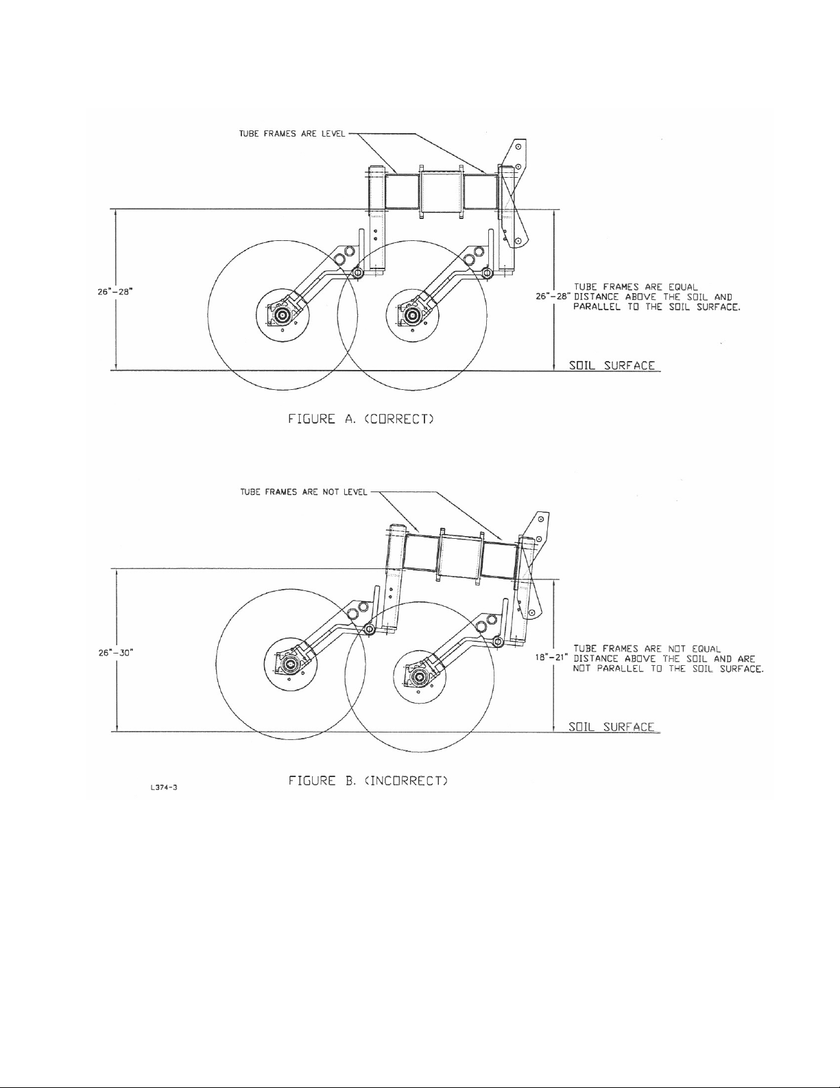
TOOLBAR FRAME HEIGHT ADJUSTMENT
Figure A. The toolbar frames are equally 26”-28” off the ground. To ensure that frame heights
are equal, it is important that measurements are taken. The tube frames should be parallel with
the soil surface.
Figure B. The hitch is set too low while the toolbar frames are not equal distance from the soil
surface.
NOTE: The illustrations are intended to show that the settings are critical. Tool frame levelness
and height adjustment are very important settings for correct performance of the coulters.
11
Page 12

OPERATION INSTRUCTIONS
RIGHT HAND ASSEMBLY
DIRECTION OF TRAVEL
1. Adjust the shoe the same front and back.
2. Start with no gap between the blade and shoe.
3. Set the shoe just touching the blade.
OPERATION MAINTENANCE
LUBRICATION: Each coulter is equipped with (3) grease zerks. To ensure longevity and
reliability of the coulter, the recommended lubrication schedule should be followed using
general purpose grease at hourly intervals indicated on symbol.
12
Page 13

13
Page 14

MAINTENANCE
Lubrication Symbols
Lubricate with grease at hourly interval indicated on symbol.
Lubrication Intervals
IMPORTANT: The recommended service intervals are based on normal
conditions; severe or unusual conditions may require more frequent
lubrication.
Perform each lubrication and service procedure at the beginning and end of each
season.
Clean grease fittings before using grease gun, to avoid injecting dirt and grit into
the bearing. Replace any lost or broken fittings immediately. If a fitting fails to
take grease, remove and clean thoroughly, replace fitting if necessary. Also
check for failure of adjoining parts.
BEARING REPLACEMENT INSTALLATION
1. When assembling the spoke wheels, bearing assembly and hubcap, be
sure to align the grease transfer hole in the spoke wheel with the groove in
the hubcap and hole in the hub to allow grease passage.
2. Assemble the wheels, hubs and caps.
3. Grease the wheel/hub/bearing assembly.
14
Page 15

MAINTENANCE
OUNCES OF GREASE
Lubrication
CAUTION: To help prevent serious injury or death to you or others
caused by unexpected movement, service machine on a level surface.
Lower machine to ground or sufficiently lock or block raised machine
before servicing. If machine is connected to tractor, engage parking
brake and place transmission in "PARK", shut off engine and remove
key. If machine is detached from tractor, block wheels and use shop
stands to prevent movement.
CAUTION: Do not clean, lubricate, or adjust machine while in motion.
Use grease based on NLGI consistency numbers and the expected air
temperature range during the service interval.
Use a multi-purpose lithium, water resistant, moderate speed, and NLGI
grade #2 grease.
Other greases may be used if they meet the following NLGI Performance
Classification: GC-LB
IMPORTANT: Some types of grease thickener are not compatible with
others. Consult your grease supplier before mixing different types of
grease.
Alternative Lubricants
Conditions in certain geographical areas may require special lubricants and
lubrication practices which do not appear in the operator's manual. If there are
any questions, consult Yetter Manufacturing Co. to obtain latest information and
recommendation.
PART #
DESCRIPTION
2987-396 CAST PRESS WHEEL 2.40 OZ
Storing Lubricants
Your machine can operate at top efficiency only if clean lubricants are used.
Use clean containers to handle all lubricants.
Store them in an area protected from dust, moisture and other contaminants.
15
Page 16

MAINTENANCE
Storing the Equipment
Store the machine in an area away from human activity
Store machine in RAISED position.
Install service locks on all wheel cylinders.
At the end of the season, the machine should be thoroughly inspected and
prepared for storage. Repair or replace any worn or damaged components to
prevent down time at the start of the next season. Store machine under cover
with all parts in operating condition.
• Clean machine thoroughly to remove all dirt, debris and crop residue,
which would hold moisture and cause rusting.
• Inspect machine for worn or broken parts. See your Yetter Farm
Equipment dealer during the off-season so that parts or service can be
acquired when machine is not needed in the field.
• Lubricate bearings as outlined in the Lubrication section
• Paint all parts which are chipped or worn and require repainting.
• Store machine in a clean, dry place with the planting unit out of the sun.
• If the machine cannot be stored inside, cover with a waterproof tarpaulin
and tie securely in place.
• Do not allow children to play on or around the machine
16
Page 17

OPERATION MAINTENANCE
BEARING ADJUSTMENT:
1. Raise the toolbar until the blade is clear of the ground. Place a safety stand under the
toolbar. Remove the blade. Remove the hub cap, cotter pin, slotted nut, washer and
spacer from the spindle shaft assembly.
2. Pull the coulter spindle shaft assembly from the hub. Remove bearing cones and seal.
3. Wash the old grease from the hub, bearing cups, coulter spindle shaft, seal and bearing
cones. Inspect the condition of bearing cups, cones and seal. Replace if necessary.
4. Apply #2 multi-purpose lithium grease on each bearing. Make sure the space around
each roller is filled. Lubricate the bearing cups.
5. Position the bearing in the cup and install the seal. Lubricate the seal lips and proceed
with re-assembly of the removed parts including the blade. Blade bolt torque is 90 to 96
ft/lbs.
6. Tighten the slotted nut to 10 to 15 ft/lbs. or until a definite drag is felt when the blade is
turned by hand. Back off the nut one slot position to line up the cotter pin hole with a slot.
Secure the nut with a new cotter pin.
KNIFE WEAR:
The lower portion of the scraper and tube are subject to wear during operation. The rate of
wear will depend on a variety of factors and in abrasive hard soil conditions the wear will be
more rapid.
NOTE: In certain areas, replacement knives should be kept in stock, replacing worn knives
as needed.
ADJUST KNIFE TO BLADE CONTACT on each opener so the blade will turn by hand with
slight resistance, but will not coast or freewheel. In loose soil the knife adjustment is
critical. If adjustment is not maintained, soil or residue may wedge between knife and
blade, resulting in the blade not turning. Because of blade run out, rotate the blade one
full revolution after adjustment. Re-adjust knife as needed. Never strike the knife with a
heavy object or damage may occur.
To adjust use shims or to adjust knife mounting out make adjustment to the nut on top of
spring for tension on blades.
17
Page 18

PARTS IDENTIFICATION
18
Page 19

PARTS IDENTIFICATION
KEY QTY. PART NUMBER DESCRIPTION
1 1 2550-065 HUB CAP, WILTON #909912-1
2 1 2986-329 MACH. CASTLE NUT 1 ¼-12
3 1 2531-124 3/16 X 2 COTTER PIN
4 1 2526-562 1 17/64 ID X 2 ¼ OD X 10 GA. MB BLK
5 2 2550-057 BEARING, KOYO #2788R
6 1 2986-403 MOUNTING HUB
1 2533-110 ¼-28 ZERK STRAIGHT SELF-TAP
2 2550-056 CUP, KOYO #2729
7 1 2550-058 SEAL, CR #17699
8 1 2986-402 25” COULTER SPINDLE
NOTE: Detail #2 is to be torqued to between 10 and 15 ft/lbs.
19
Page 20

PARTS IDENTIFICATION
20
Page 21

PARTS IDENTIFICATION
21
Page 22

PARTS IDENTIFICATION
22
Page 23

PARTS IDENTIFICATION
23
Page 24

PARTS IDENTIFICATION
24
Page 25

PARTS IDENTIFICATION
25
Page 26

PARTS IDENTIFICATION
26
Page 27

PARTS IDENTIFICATION
27
Page 28

PARTS IDENTIFICATION
28
Page 29

PARTS IDENTIFICATION
29
Page 30

PARTS IDENTIFICATION
30
Page 31

PARTS IDENTIFICATION
31
Page 32

PARTS IDENTIFICATION
32
Page 33

PARTS IDENTIFICATION
33
Page 34

PARTS IDENTIFICATION
34
Page 35

NOTES
35
Page 36

Our name
Is getting known
Just a few years ago, Yetter products were sold primarily to the
Midwest only. Then we embarked on a program of expansion and
moved into the East, the South, the West and now north into Canada.
We’re even getting orders from as far away as Australia and Africa.
So, when you buy Yetter products . . .you’re buying a name that’s
recognized. A name that’s known and respected. A name that’s
become a part of American agriculture and has become synonymous
with quality and satisfaction in the field of conservation tillage.
Thank you.
YETTER MANUFACTURING CO.
Colchester, IL 62326-0358 • 309/776-4111
Toll Free 800/447-5777
Fax 309/776-3222
Website: WWW.YETTERCO.COM
E-MAIL: INFO@YETTERCO.COM
36
2565-758_REV_I 04/2014
 Loading...