

Page 1

2984 Series MAVERICK
OPERATOR & PARTS MANUAL
2565-762_REV_G • 02-2013
YETTER MANUFACTURING CO.
FOUNDED 1930
COLCHESTER, IL 62326-0358
TOLL FREE: 800/447-5777
309/776-3222 (FAX)
WEBSITE: WWW.YETTERCO.COM
E-MAIL: INFO@YETTERCO.COM
HR PLUS
Page 2

TABLE OF CONTENTS
FOREWORD…………………………………………………………3
WARRANTY………………………………………………………….3
SAFETY………………………………………………………………4
BOLT TORQUE……………………………………………………..5
ASSEMBLY INSTRUCTIONS………………………………….6-17
OPERATION……………………………………………………18-22
MAINTENANCE………………………………………………..23-30
PARTS IDENTIFICATION…………………………………….31-49
TROUBLESHOOTING…………………………………………50-51
2
Page 3

FOREWORD
You’ve just joined an exclusive but rapidly
growing club.
For our part, we want to welcome you to the
group and thank you for buying a Yetter product.
We hope your new Yetter products will help you
achieve both goals-increase your productivity and
increase your efficiency so that you may generate
more profit.
This operator’s manual has been designed into
four major sections: Foreword, Safety
Precautions, Installation Instructions, and Parts
Breakdown.
This SAFETY ALERT SYMBOL indicates
important safety messages in the manual.
When you see this symbol, be alert to the
possibility of PERSONAL INJURY and carefully
read the message that follows.
The word NOTE is used to convey information
that is out of context with the manual text. It
contains special information such as
specifications, techniques and reference
information of a supplementary nature.
The word IMPORTANT is used in the text when
immediate damage will occur to the machine due
to improper technique or operation. Important will
apply to the same information as specified by
note only of an immediate and urgent nature.
It is the responsibility of the user to read the
operator’s manual and comply with the safe and
correct operating procedure and to lubricate and
maintain the product according to the
maintenance schedule in the operator’s manual.
The user is responsible for inspecting his
machine and for having parts repaired or
replaced when continued use of the product
would cause damage or excessive wear to the
other parts.
It is the user’s responsibility to deliver his
machine to the Yetter dealer who sold him the
product for service or replacement of defective
parts, which are covered by the warranty policy.
If you are unable to understand or follow the
instructions provided in this publication, consult
your local Yetter dealer or contact:
YETTER MANUFACTURING CO.
309/776-4111
800/447-5777
309/776-3222 (FAX)
Website: www.yetterco.com
Email: info@YetterCo.com
WARRANTY
Yetter Manufacturing warrants all products manufactured and sold by it against defects in material. This
warranty being expressly limited to replacement at the factory of such parts or products as shall appear to
be defective after inspection. This warranty does not obligate the Company to bear cost of labor in
replacement of parts. It is the policy of the Company to make improvements without incurring obligations to
add them to any unit already sold. No warranty is made or authorized to be made, other than herein set
forth. This warranty is in effect for one year after purchase.
Dealer ___________________________________________________
Yetter Manufacturing warrants its own products only and cannot be responsible for damages to
equipment on which mounted.
3
Page 4

SAFETY
A brief description of signal words that may be used in this manual:
CAUTION: Used as a general reminder of good safety practices or to direct attention to unsafe
practices.
WARNING: Denotes a specific potential hazard
DANGER: Denotes the most serious specific potential hazard.
SAFETY PRECAUTIONS
You can make your farm a safer place to live and work if you observe the safety precautions given. Study
these precautions carefully and insist that they be followed by those working with you and for you.
Finally, remember this: an accident is usually caused by someone’s carelessness, neglect or oversight.
WARNING
Never clean, lubricate or adjust a machine that is in motion. Always
lower or block the implement before performing service.
If machine must be serviced in the raised position, jack or block it up to prevent it from accidentally falling
and injuring someone.
Do not allow riders on the tractor or implement.
Use speeds and caution dictated by the terrain being traversed. Do not operate on any slope steep enough
to cause tipping or loss of control.
Be sure all personnel are clear of the immediate area before operating.
Read and understand the operator’s manual and require all other persons who will operate the equipment
to do the same.
Be familiar with all tractor and implement controls and be prepared to stop engine and implements quickly in
an emergency.
CAUTION
Consult your implement and tractor operator’s manual for correct and safe operating practices.
Beware of towed implement width and allow safe clearance.
FAILURE TO HEED MAY RESULT IN PERSONAL INJURY OR DEATH.
4
Page 5

BOLT TORQUE
Note: Right hand and left hand designations are based on sitting in the tractor and facing forward.
READ THESE INSTRUCTIONS FIRST:
1. Improperly tightened bolts will result in damage, breakage, expense, and down time.
2. Always replace bolts with the specified grade and type.
3. Torque properly before first use of the machine and every 2-4 hours of use until you are sure bolts
are staying tight.
4. The chart below is a guide for proper torque. Use it unless a specified torque is called out
elsewhere in the manual.
5. Torque is the force you apply to the wrench handle or the cheater bar, times the length of the
handle or bar.
6. Use a torque wrench whenever possible.
The following table shows torque in ft. lbs.
Lubricate all bearings and moving parts as assembled and make certain that they work freely.
WARNING:
without using safety lockups.
CAUTION:
attention to lifting techniques while handling and or maneuvering the opener during
assembly. Failure to do so may lead to personal injury.
Never work around the toolbar / implement while in a raised position
The MAVERICK OPENER™ and its attachments are very heavy. Extra
5
Page 6
ASSEMBLY INSTRUCTIONS
2984 MAVERICK OPENER
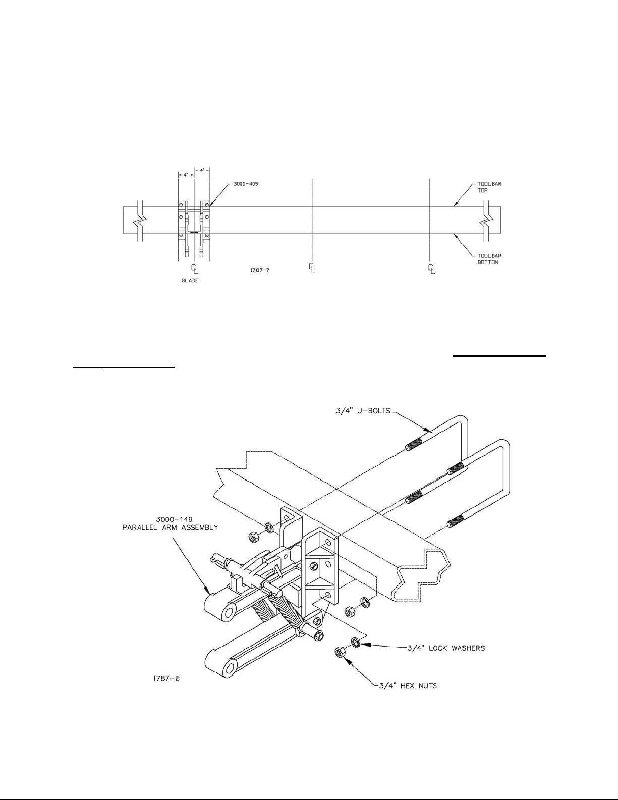
STEP 1. Mark the location of the center of each row on the toolbar. Then measure from row 4” and place a
mark on the rear side of toolbar. This mark will give a reference point to where the edge of the clamp
bracket (3000-409) should be located so that the fertilizer knife will be centered directly on the row.
STEP 2. Centering on each row, attach the (3000-149) parallel arm assembly to the toolbar with the
appropriate ¾” u-bolts, lock washers and hex nuts. Torque the u-bolts to 200 ft. lbs. Recheck the torque
after 10 hours of use.
™
6
Page 7
ASSEMBLY INSTRUCTIONS
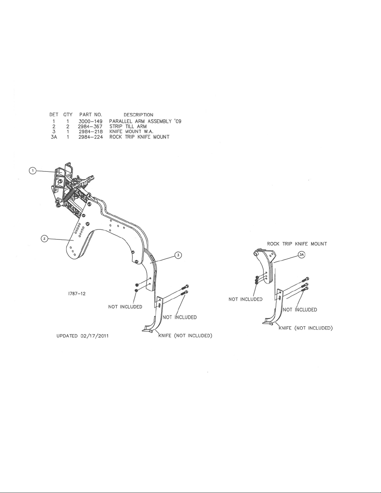
STEP 3. Attach the fertilizer knife to the 2984 knife mount using 2) ½” x 2” GRADE. 8 bolts and lock nuts.
(Rock Trip model use 3) ½” x 2” GRADE 8)
STEP 4. Tighten all bolts to recommended torques from the table of this manual, unless the torque is
otherwise specified.
Note: Do not over tighten the spindle bolt and castle nut. Torque the spindle bolt to 13-15 ft. lbs. or until
the hub/blade assembly has a slight drag when turned by hand. Tighten the nut one slot position on the
castle nut to line up the cotter pin hole. Secure the nut with the 1/8” x 1” cotter pin provided.
Recheck the torque on these bolts after 10 hours of operation and then every 50 hours after that. Do a
routine inspection of the opener at this time for best performance and less down time.
7
Page 8
ASSEMBLY INSTRUCTIONS
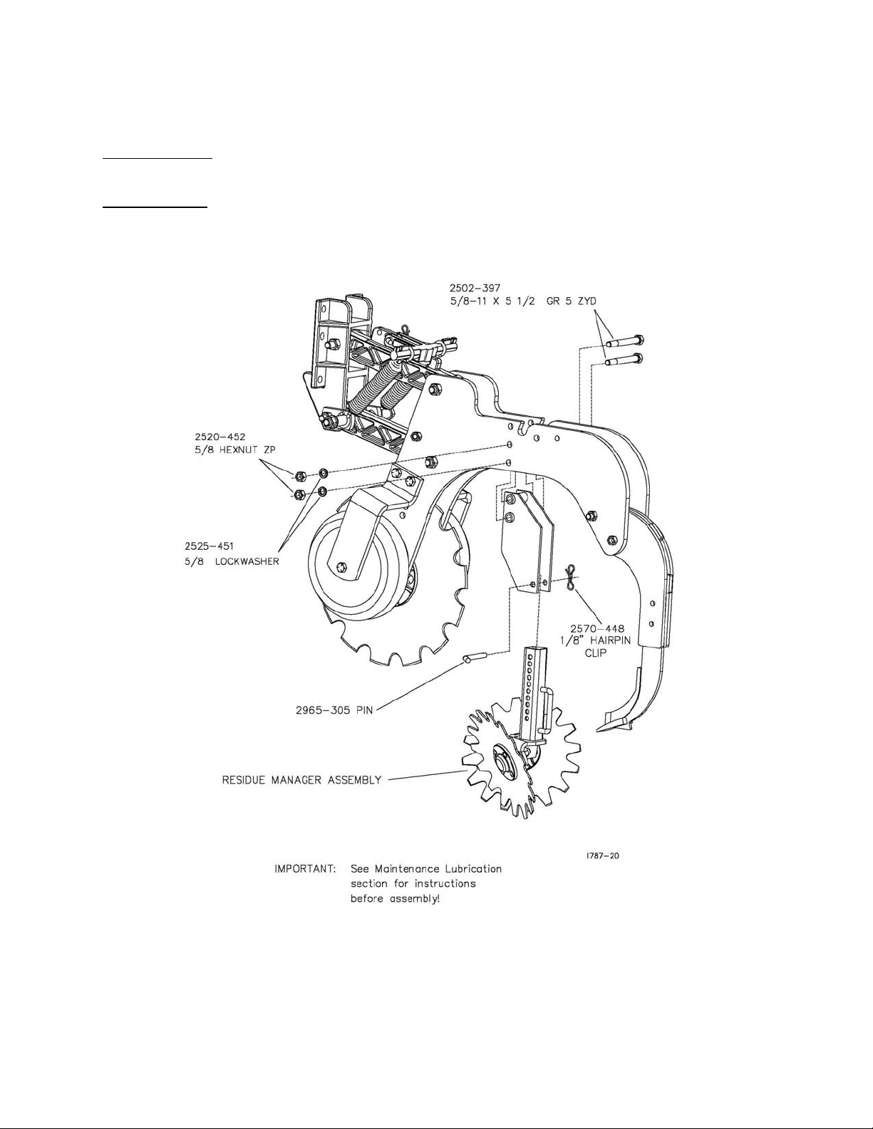
2984-028-ST - RESIDUE MANAGER
2984-029-ND - RESIDUE MANAGER
STEP 1. Install the wheel stem assembly
Initial Adjustment for the residue manager needs to be set at soil surface. For example: fertilizer is to be
placed 6” deep, the residue manager should be adjusted 6” above the tip of the knife.
Field adjustment: In field adjustments to the residue manager will need to be done for best performance of
residue manager. As conditions change, soil types, tilth, moisture, amount of residue, type of residue, the
residue manager’s depth adjustment may also need to change.
8
Page 9
STEP 1.
ASSEMBLY INSTRUCTIONS
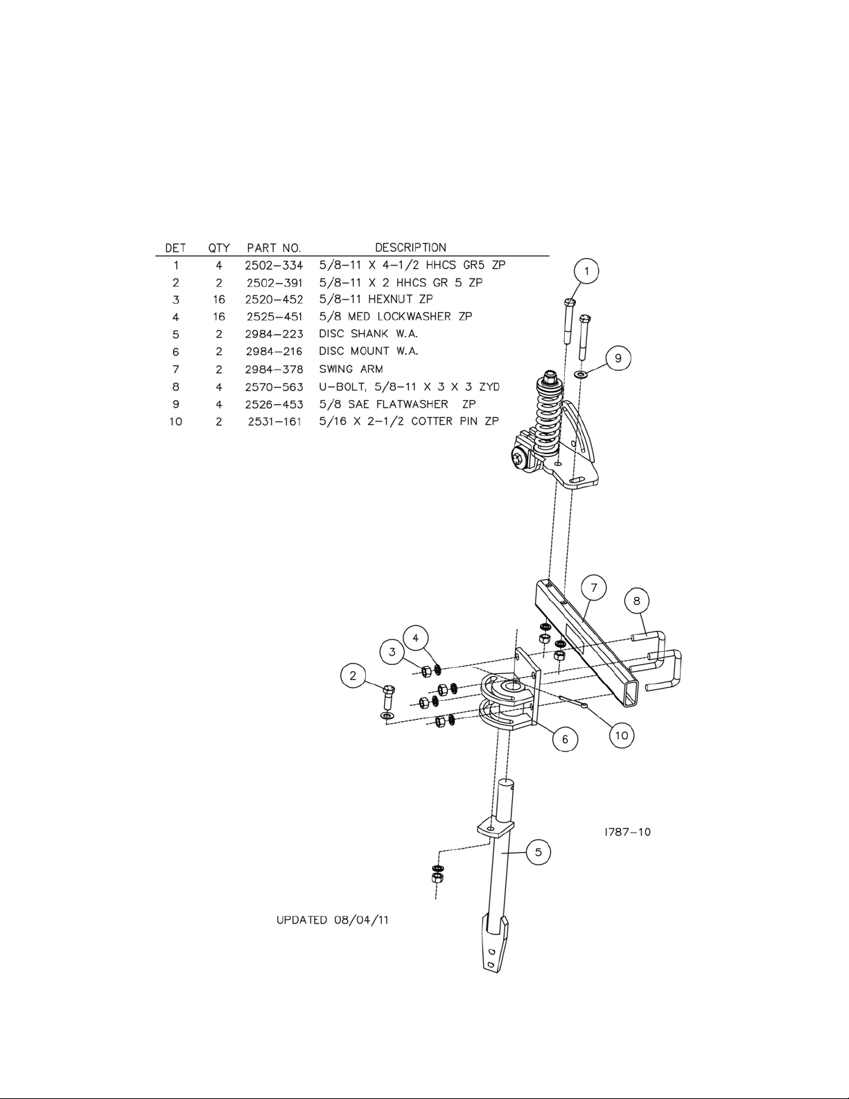
2984-030-N – NOTCHED DISC SEALER KIT
2984-030-S – SMOOTH DISC SEALER KIT
9
Page 10
STEP 2:
ASSEMBLY INSTRUCTIONS
2984-030-N – NOTCHED DISC SEALER KIT
2984-030-S – SMOOTH DISC SEALER KIT
10
Page 11
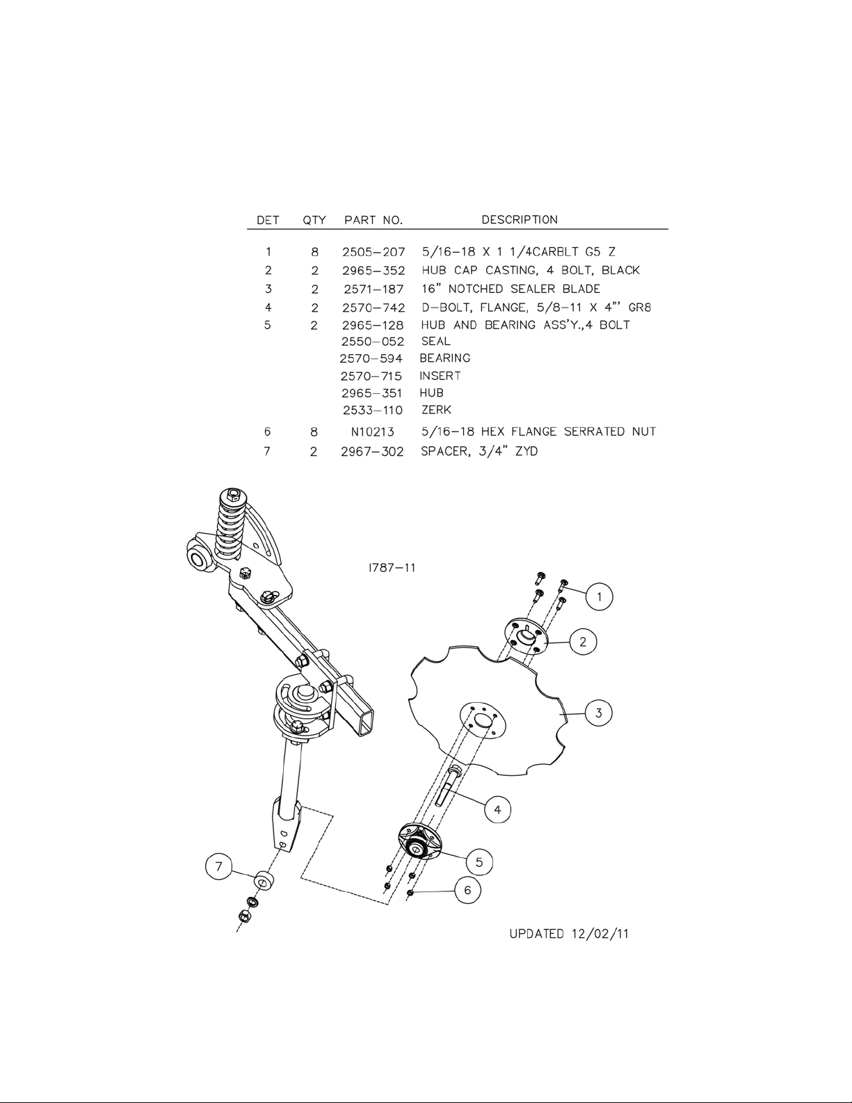
ASSEMBLY INSTRUCTIONS
2984-030-N – NOTCHED DISC SEALER KIT
2984-030-S – SMOOTH DISC SEALER KIT
STEP 3. Attach the blade/hub assembly to the 2920-329 L-bracket using the D-bolt through a 5/8” lock
washer and 5/8” hex nut. Torque 150 ft.lbs.
11
Page 12
ASSEMBLY INSTRUCTIONS
TRAVEL
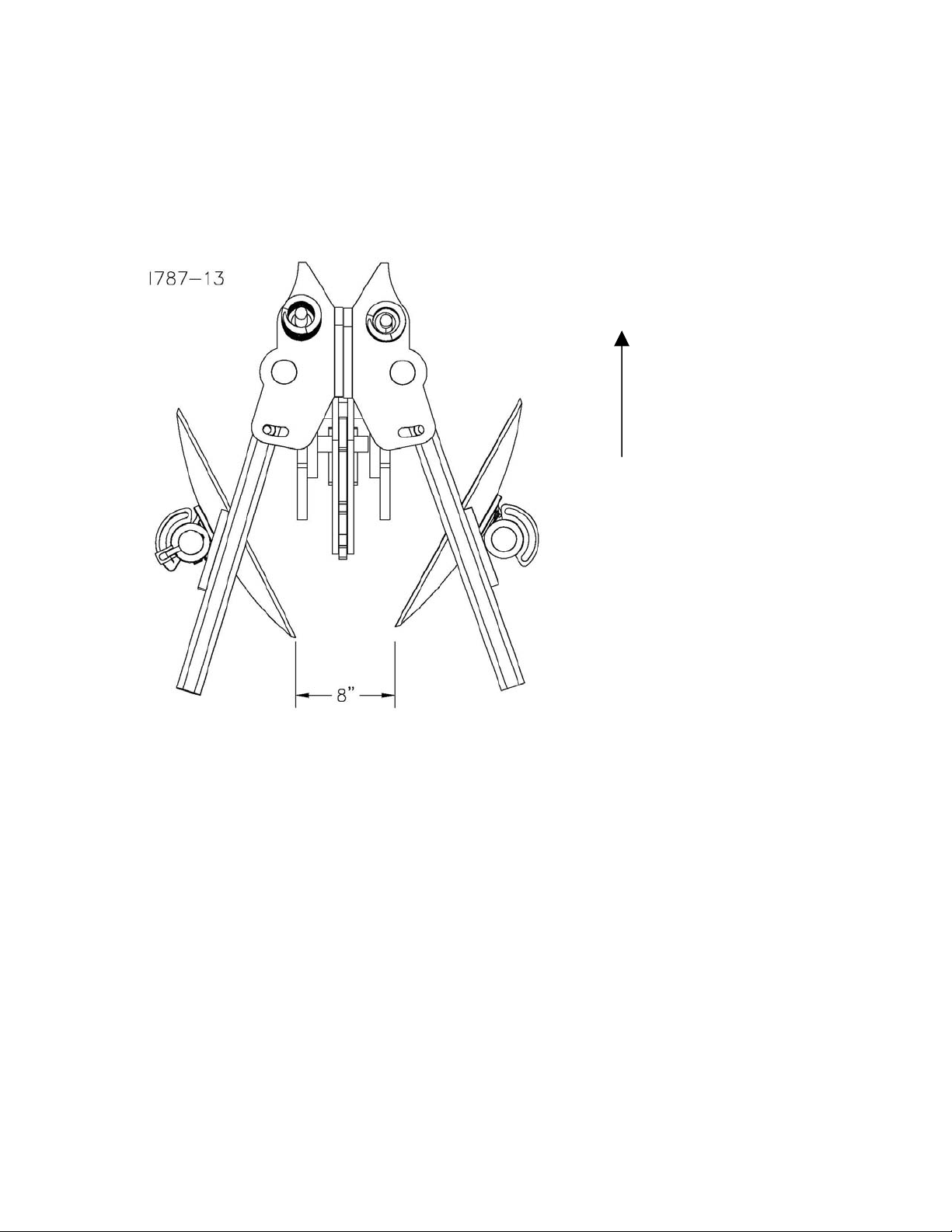
2984-030-N – NOTCHED DISC SEALER KIT
2984-030-S – SMOOTH DISC SEALER KIT
STEP 4. Adjust the angle of the disc blades so that the blades are approximately 8” apart and 4” from the
center of the knife.
STEP 5. Tighten all of the hardware to the recommended torque unless otherwise stated.
12
Page 13
ASSEMBLY INSTRUCTIONS
STEP 1.
secure with 5/8” lock hex nuts.
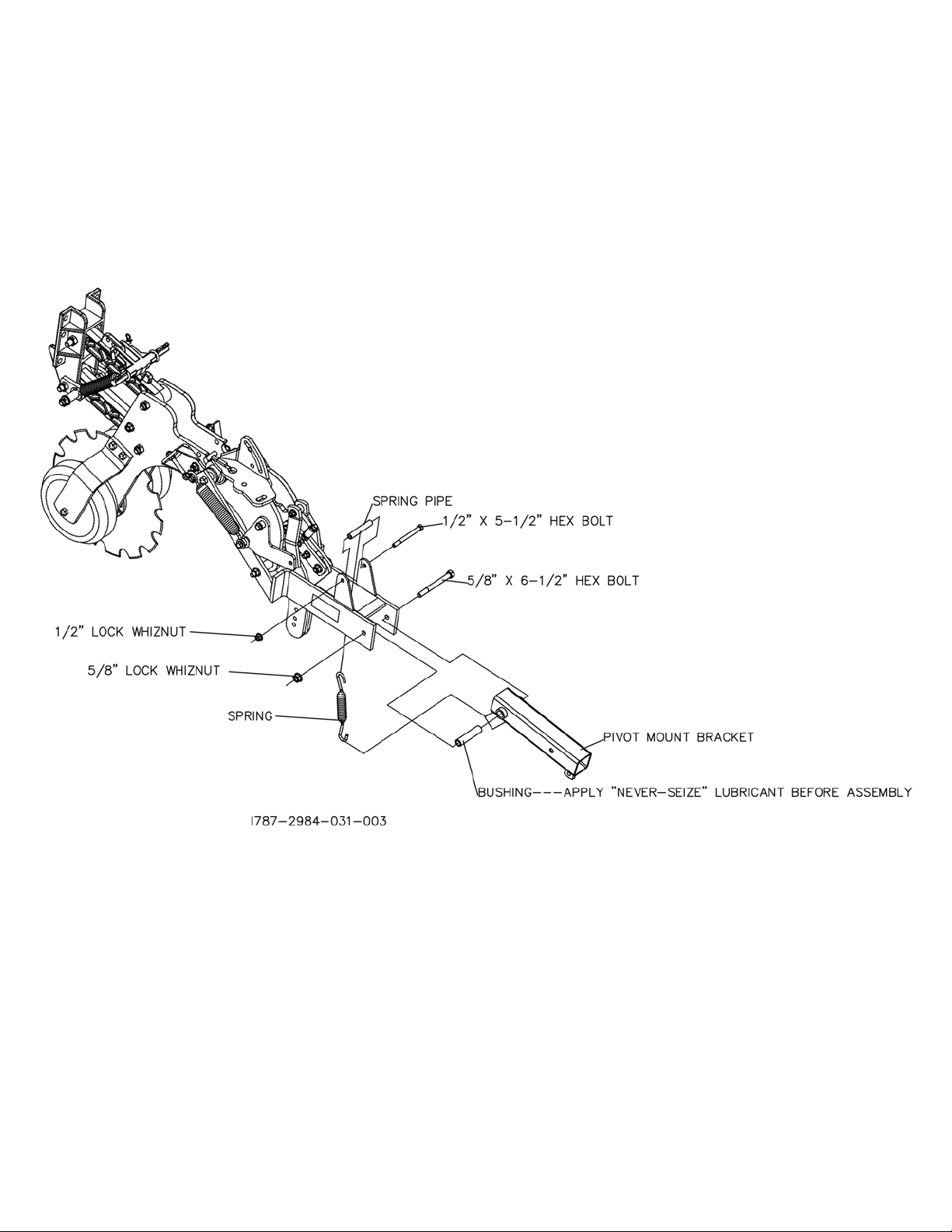
Attach Rolling Basket mount bracket to the Maverick ™ Opener using the 5/8” X 6 ½” hex bolts,
ROLLING BASKET ATTACHMENT
13
Page 14
ASSEMBLY INSTRUCTIONS
ROLLING BASKET ATTACHMENT
STEP 2. Attach the pivot bracket and bushing (apply “never seize” lubrication to the bushing
before installing) to the mount bracket using the 5/8” x 6 ½” hex bolt and 5/8” lock hex nut.
14
Page 15
ASSEMBLY INSTRUCTIONS
ROLLING BASKET ATTACHMENT
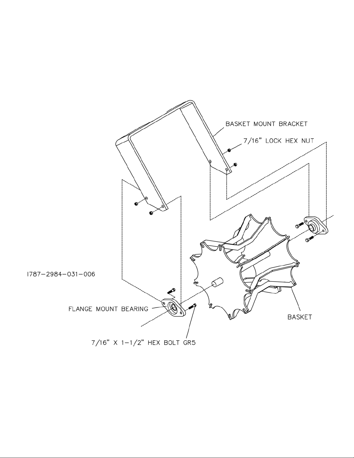
STEP 3. Install the basket with flange mount bearings to the basket mount bracket using (4) 7/16”
x 1 ½” hex bolt and 7/16” lock hex nut.
15
Page 16

ASSEMBLY INSTRUCTIONS
ROLLING BASKET ATTACHMENT
STEP 4. Center the basket in the basket mount bracket and “triple tighten” the set screws.
16
Page 17

ASSEMBLY INSTRUCTIONS
ROLLING BASKET ATTACHMENT
STEP 5. Attach the basket mount bracket to the pivot bracket using the 5/8” x 4 ½” hex bolt and
5/8” lock hex nut. Also, install the adjustment pin and 1/8” hairpin cotter.
17
Page 18

For proper operation, the toolbar frame must operate level (for, aft. and
OPERATION
YETTER model 2984 MAVERICK OPENER is a multi-functional tool designed for use in a fertilizer
management system. It is capable of residue management, precision fertilizer placement, soil tilth, and soil
berm/mound building all in one pass. Thus creating a seedbed that will increase your Return On
Investment.
It is important to know that the 2984 MAVERICK OPENER unit is similar to a row crop planter unit in
operation, thus it is very important to adjust the frame height and levelness for best performance. Soil
conditions (i.e.; frozen soil, rocks, heavy, tough residue) have a major influence on the performance of the
MAVERICK OPENER™. If damp soil is building up on the wheels, discs or knives then conditions are less
than ideal and the unit will not perform at its best.
CAUTION:
OPENER™.
IMPORTANT:
side to side) and at the correct height, typically 24”.
In hard or rocky soil conditions, the desired operating depth of the knife may not be possible. Increase the
spring pressure to obtain the desired depth rather than lower the toolbar frame below the 24” recommended
setting. Toolbar weight may limit operating depth in hard soil conditions; add ballast to the toolbar frame.
Example 200#’s per opener have been added to the frame to achieve the desired depth. Operating depth
of the MAVERICK OPENER™ is affected by spring tension, toolbar height, and levelness of toolbar and soil
tilth. As soil conditions change, toolbar settings and coulter adjustments will need to be changed as well.
Toolbar gauge wheel kits are optional but advocated for use with the MAVERICK OPENER™ because of
toolbar frame height being critical for proper operation, 24”.
1. Set/mount coulter blades to run perpendicular to the soil. Operation depth and blade wear can be
affected if the coulter mounted crooked or if the toolbar is not level side to side.
2. After a few hours of use, check all bolts for tightness and proper torque.
3. After a day of use (10-12 hours) check coulter hubs for loose bearings. There should be no
endplay in the hub bearings allowing the blade to wobble. If necessary, remove cotter pin and
adjust the slotted nut to remove wobble, recommended torque of 13 ft. lbs. and re-insert cotter pin.
If the wobble or looseness cannot be corrected, the bearings, cups and seals will need to be
replaced. DO NOT REUSE WORN OR DAMAGED PARTS.
Frozen soil or heavy rock population may cause damage to the MAVERICK
18
Page 19

OPERATION
WARNING
Never clean, lubricate or adjust a machine that is in motion. Always lower or block the implement before
performing service.
If machine must be serviced in the raised position, jack or block it up to prevent it from accidentally falling
and injuring someone.
Do not allow riders on the tractor or implement.
Use speeds and caution dictated by the terrain being traversed. Do not operate on any slope steep enough
to cause tipping or loss of control.
Be sure all personnel are clear of the immediate area before operating.
Read and understand the operator’s manual and require all other persons who will operate the equipment
to do the same.
Be familiar with all tractor and implement controls and be prepared to stop engine and implements quickly in
an emergency.
FAILURE TO HEED MAY RESULT IN PERSONAL INJURY OR DEATH.
NOTE:
operated.
STEP 1. Set the toolbar frame height at 24”. This height, from the top of the soil to the bottom of the
toolbar, seems to work for the best performance of the MAVERICK OPENER™. Adjust the toolbar gauge
wheels up or down to get the 24” from the bottom of the gauge wheel to the bottom of the toolbar. Adjust
the spring tension on the upper parallel arm; forward for lighter setting and rearward for heavier setting
(TWO ADDITIONAL SPRINGS ARE AVAILABLE IF NEEDED). The pin must be installed to hold the spring
bar at the desired setting. Add or remove weight to the toolbar to achieve the proper toolbar frame height.
NOTE: Toolbar frame levelness and height adjustments are very important settings for correct performance
of the coulters.
Adjustments to the MAVERICK OPENER™ are best done while in the field where the unit is to be
19
Page 20

OPERATION
STEP 1. Disengage Rolling Basket Attachment – Lift basket and insert pin. See diagram.
20
Page 21

OPERATION
STEP 2. Set the coulter depth based on soil conditions, (i.e. tilth, stones or crop residue). For proper
operation of the MAVERICK OPENER, the coulter must cut through crop residues including roots. For
best performance 3”-4” depth is recommended. Raising the blade helps to cut residue rather than pushing
it ahead and not cutting. Operating the blade deep puts the hub and mounting plates close to the surface
and may create plugging in heavy residue.
STEP 3. Set the depth of the knife by adjusting toolbar height and spring tension on the parallel arms.
STEP 4. Adjust the residue manager to move crop residue aside and not move any soil. Adjustments to
the residue manager may have to be made when changing field conditions and type and amount of residue.
ROW CLEANER DO’s AND DON’T’s:
1. DO NOT move soil; Residue Managers are designed to move crop residue only.
2. DO NOT operate toolbar at slow speeds, ground speed affects how aggressive the spoke
wheels are; operate at sufficient speed (5-7 mph) to maintain good residue flow.
3. DO NOT expect 100% of crop residue to be cleared, it is not necessary and would
necessitate engaging the soil. The width of path cleared depends on ground conditions,
depth setting and ground speed.
4. DO expect to see wheels occasionally quit turning, indicates ideal (shallow) setting which is
not moving soil.
5. DO adjust toolbar frame height 24” and levelness. Very important to ensure L749
MAVERICK OPENER
6. DO adjust MAVERICK OPENER
STEP 5. Adjust the Sealing Discs/Wheels. The width and height of the mound/berm depends on ground
conditions, depth setting, spring tension, blade angle and ground speed. A popular setting for the blade
adjustment is 8” at the rear of the blades, equal distance from the center of the row.
will follow ground contours properly.
down pressure kit correctly to prevent excessive depth.
21
Page 22

OPERATION – ADJUSTMENT
22
Page 23

MAINTENANCE
LUBRICATION: USE #2 MULTI-PURPOSE LITHIUM GREASE
To ensure longevity and reliability of the MAVERICK OPENER HR Plus, the recommended
lubrication schedule should be followed using multi-purpose grease at intervals as indicated.
BEARING ADJUSTMENT:
1. Raise the toolbar until the blade is clear of the ground. Place a safety stand under the toolbar.
Remove the cotter pin, slotted nut, washer and bolt from the hub assembly. Remove the blade
from the hub assembly.
2. Remove bearing cones and seal from the hub.
3. Wash the old grease from the hub, bearing cups, spindle spacers, seals and bearing cones.
Inspect the condition of bearing cups, cones and seals. Replace if necessary.
4. Apply #2 multi-purpose lithium grease on each bearing. Make sure the space around each roller is
filled. Lubricate the bearing cups.
5. Position the bearing in the cup and install the seal. Lubricate the seal lips and proceed with reassembly of the removed parts including the blade. Blade bolt torque is 90 to 96 ft/lbs.
6. Tighten the slotted nut to 10 to 15 ft/lbs. or until a definite drag is felt when the blade is turned by
hand. Tighten the nut one slot position to line up the cotter pin hole with a slot. Secure the nut with
a new cotter pin.
KNIFE WEAR:
The lower portion of the knife and tube are subject to wear during operation. The rate of wear will
depend on a variety of factors and in abrasive soil conditions the wear will be more rapid.
NOTE: In certain areas, replacement knives should be kept in stock, replacing worn knives as needed.
23
Page 24

MAINTENANCE
BEARING ASSEMBLY AND LUBRICATION
Practice Safety
Understand and practice safe service procedures before doing work. Follow ALL the
operating, maintenance and safety information in the equipment operator manual. Clear
the area of bystanders, especially small children, when performing any maintenance or
adjustments. Keep work area clean and dry. Use adequate lighting for the job. Use only
tools, jacks and hoists of sufficient capacity for the job.
Never lubricate, service, or adjust machine while it is moving. Keep hands, feet, and
clothing from power-driven moving and rotating parts. Disengage all power and operate
controls to relieve pressure. Lower equipment to the ground and stop the engine.
Remove the key. Wait for all moving parts to stop before servicing, adjusting, repairing or
unplugging.
Securely support any machine elements with blocks or safety stands that must be raised
for service work.
Keep all parts in good condition and properly installed. Fix damaged equipment
immediately. Replace worn or broken parts. Remove any buildup of grease, oil, or debris.
Make sure all guards are in place and properly secured when maintenance work is
completed.
24
Page 25
MAINTENANCE
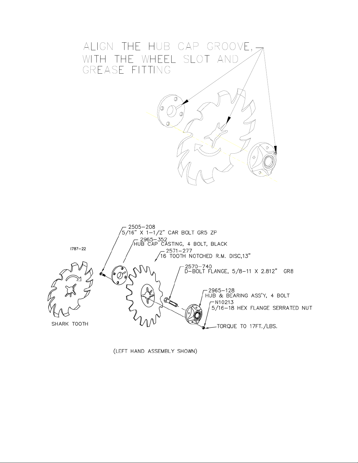
NOTE: Be certain to align the grease fitting with the slot in the wheel and the hubcap so
that the grease can flow freely.
25
Page 26

MAINTENANCE
Grease must fill this
Hubcap cavity.
26
Page 27

MAINTENANCE
Lubrication
CAUTION: To help prevent serious injury or death to you or others caused by
unexpected movement, service machine on a level surface. Lower machine to
ground or sufficiently lock or block raised machine before servicing. If machine
is connected to tractor, engage parking brake and place transmission in
"PARK", shut off engine and remove key. If machine is detached from tractor,
block wheels and use shop stands to prevent movement.
CAUTION: Do not clean, lubricate, or adjust machine while in motion.
Use grease based on NLGI consistency numbers and the expected air temperature range
during the service interval.
Use a multi-purpose lithium, water resistant, moderate speed, and NLGI grade #2
grease.
Other greases may be used if they meet the following NLGI Performance Classification:
GC-LB
IMPORTANT: Some types of grease thickener are not compatible with others.
Consult your grease supplier before mixing different types of grease.
Alternative Lubricants
Conditions in certain geographical areas may require special lubricants and lubrication
practices which do not appear in the operator's manual. If there are any questions,
consult Yetter Manufacturing Co. to obtain latest information and recommendation.
PART #
2967-602 13” SHARK TOOTH R.M. WHEEL 1.12 OZ
2571-277 16 TOOTH NOTCHED R.M. DISC,13" 1.12 OZ
DESCRIPTION OUNCES OF GREASE
Storing Lubricants
Your machine can operate at top efficiency only if clean lubricants are used. Use clean
containers to handle all lubricants. Store them in an area protected from dust, moisture,
and other contaminants.
27
Page 28

MAINTENANCE
Lubrication Symbols
Lubricate with grease at hourly interval indicated on symbol.
Lubrication Intervals
IMPORTANT: The recommended service intervals are based on normal conditions;
severe or unusual conditions may require more frequent lubrication.
Perform each lubrication and service procedure at the beginning and end of each season.
Clean grease fittings before using grease gun, to avoid injecting dirt and grit into the
bearing. Replace any lost or broken fittings immediately. If a fitting fails to take grease,
remove and clean thoroughly, replace fitting if necessary. Also check for failure of
adjoining parts.
28
Page 29

MAINTENANCE
• Always lubricate the implement thoroughly
before taking it to the field.
• Always lower the implement until all shank
points rest on the ground.
• Lubricate fittings and bushings as indicated
in the diagram below.
• Be sure grease fittings are free from dirt and
paint so the lubricant is certain to enter the
proper areas. Clean fittings thoroughly before using.
• Use No. 2 multi-purpose lithium grease
29
Page 30

MAINTENANCE
Storing the Equipment
Store the machine in an area away from human activity.
Store machine in RAISED position.
Install service locks on all wheel cylinders.
At the end of the season, the machine should be thoroughly inspected and prepared for
storage. Repair or replace any worn or damaged components to prevent down time at the
start of the next season. Store machine under cover with all parts in operating condition.
• Clean machine thoroughly to remove all dirt, debris and crop residue, which would
hold moisture and cause rusting.
• Inspect machine for worn or broken parts. See your Yetter Farm Equipment dealer
during the off-season so that parts or service can be acquired when machine is not
needed in the field.
• Lubricate bearings as outlined in the Lubrication section
• Paint all parts which are chipped or worn and require repainting.
• Store machine in a clean, dry place with the planting unit out of the sun.
• If the machine cannot be stored inside, cover with a waterproof tarpaulin and tie
securely in place.
• Do not allow children to play on or around the machine
30
Page 31

PARTS IDENTIFICATION
3000-131 PLATE ASSEMBLY
31
Page 32

PARTS IDENTIFICATION
32
Page 33

PARTS IDENTIFICATION
2984-029-ND-R (SHOWN)
2984-029-ND-L
33
Page 34

PARTS IDENTIFICATION
34
Page 35

PARTS IDENTIFICATION
2984-028-ST
35
Page 36

PARTS IDENTIFICATION
36
Page 37

PARTS IDENTIFICATION
37
Page 38

PARTS IDENTIFICATION
38
Page 39

PARTS IDENTIFICATION
39
Page 40

PARTS IDENTIFICATION
40
Page 41

PARTS IDENTIFICATION
41
Page 42

PARTS IDENTIFICATION
42
Page 43

PARTS IDENTIFICATION
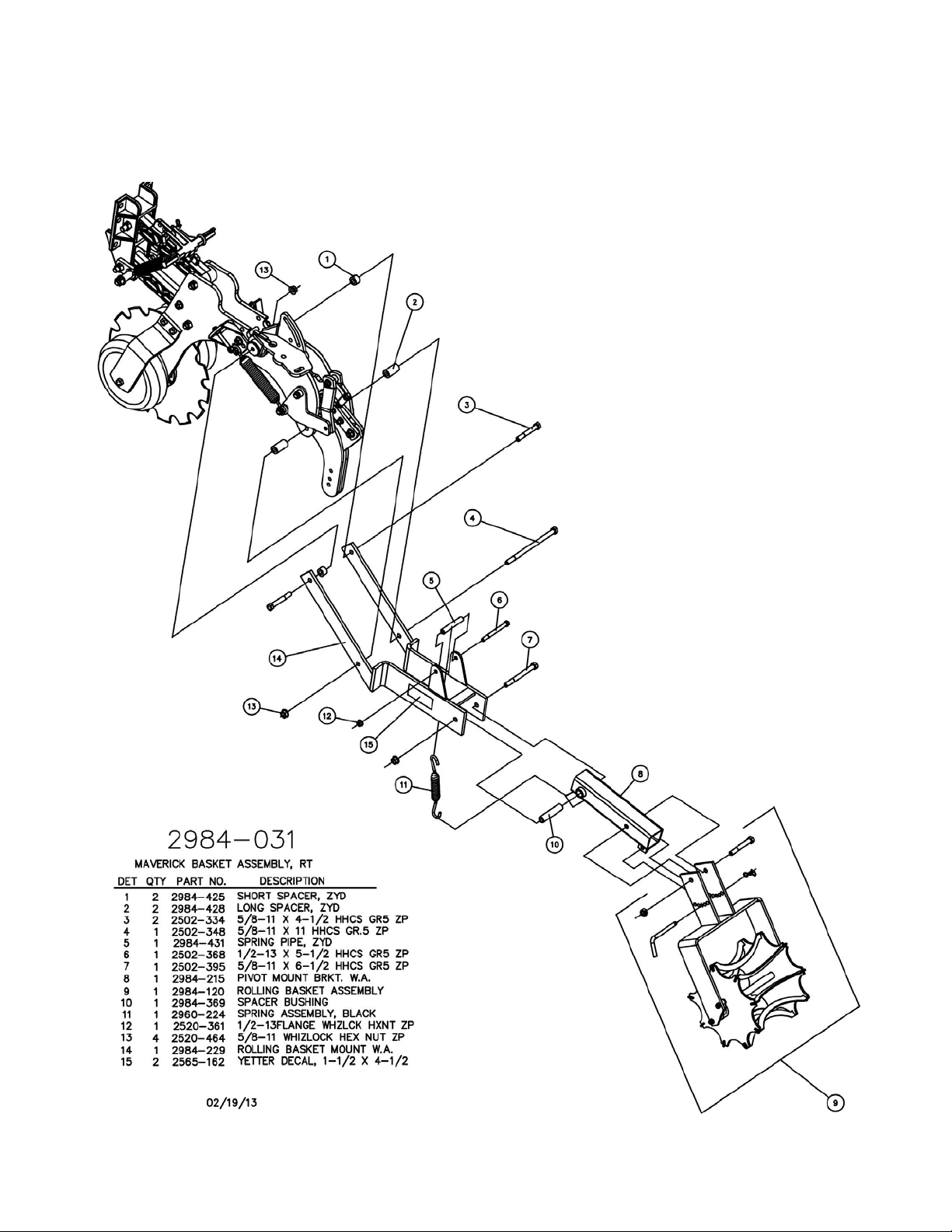
2984-123-N-RT
2984-123-S-RT
43
Page 44

PARTS IDENTIFICATION
44
Page 45

PARTS IDENTIFICATION
45
Page 46

PARTS IDENTIFICATION
46
Page 47

PARTS IDENTIFICATION
47
Page 48

PARTS IDENTIFICATION
48
Page 49

PARTS IDENTIFICATION
49
Page 50

PROBLEM
Poor overall performance
Toolbar height too high
Shallow knife penetration
Disc Sealer blade & hub fall
off
Disc Sealer not creating a
mound or too small of a
mound
TROUBLESHOOTING
CAUSE
Toolbar not adjusted correctly
Unit is not set correctly
Too much down pressure
spring tension
Toolbar gauge wheels
adjusted too low
Speed too slow
Toolbar height too high
Insufficient down pressure
Washer not installed in the
disc assembly.
Speed too slow
Blades are not set
aggressively enough
Down pressure spring is loose
Toolbar is not level-probably
nose down
SOLUTION
Adjust the toolbar so that
during operation it is level and
at a height of 24” from the
bottom of the toolbar to the
soil surface.
See Operations section for
proper adjustments
Remove two outer springs &
set in light pressure setting
Raise gauge wheels
Operate at 5 mph minimum
Must have toolbar operating
at 24” above the soil surface
Set down pressure spring
adjustment to the rear hole
Inspect springs for breakage
and/or wear
Adjust toolbar height lower.
Normally 24”
See Parts Identification for
proper assembly.
Operate at 5mph minimum
Increase the angle of the front
edge of blade to the row.
Tighten the coil spring by
compressing; tighten the 3/4”
hex nut onto the pushrod.
Level toolbar at a height of
24” from soil surface.
50
Page 51

TROUBLESHOOTING
PROBLEM POSSIBLE CAUSE SOLUTION
Berm size or shape Disc sealer blades not at Adjust blades to
Is not uniform equal angle exact same angle
Insufficient spring pressure Change spring
On rolling basket attachment to increase
Down pressure
(See adjustments)
Large clods or chunks Insufficient sprint pressure Change spring
On rolling basket attachment to increase
Down pressure
(see adjustments)
Coulter cutting blade running Operate coulter
Too deep cutting blade just
Deep enough to
Slice crop residue
Fertilizer knife too deep Operate knives
shallower
Residue or mud plugging Disc sealer blades have Decrease disc
Too much angle sealer angle
Conditions too wet Lock up rolling
Basket attachment
51
Page 52

Our name
Is getting known
Just a few years ago, Yetter products were sold primarily to the
Midwest only. Then we embarked on a program of expansion and
moved into the East, the South, the West and now north into Canada.
We’re even getting orders from as far away as Australia and Africa.
So, when you buy Yetter products . . .you’re buying a name that’s
recognized. A name that’s known and respected. A name that’s
become a part of American agriculture and has become synonymous
with quality and satisfaction in the field of conservation tillage.
Thank you.
YETTER MANUFACTURING CO.
Colchester, IL 62326-0358 • 309/776-4111
Toll Free 800/447-5777
Fax 309/776-3222
Website: WWW.YETTERCO.COM
E-mail: INFO@YETTERCO.COM
2565-762_REV_G • 02/2013
52
 Loading...