

Yetter 2968-050, 2968-051, 2968-052, 2968-053 Set-up / Parts Manual

YETTER MANUFACTURING CO.
FOUNDED 1930
Colchester, IL 62326-0358
Toll free: 800/447-5777
309/776-3222 (Fax)
Website: www.yetterco.com
E-mail: info@yetterco.com
ROW UNIT MID-MOUNT
FERTILIZER INJECTION OPENER
MODELS 2968-050 & 2968-052 – SINGLE WHEEL
MODELS 2968-051 & 2968-053 – DUAL WHEEL
CNH ROW UNITS
SET UP & PARTS MANUAL
2565-960 – 02/2019
FOREWORD ………………………………………………….......…............... 3
SAFETY …………………………………………………………...….................. 4
PICTORIAL PART LIST …………………...……………................... 5 – 10
INSTALLATION …………………………………………………........... 10 – 16
OPERATION .....………..……..…...…………........................... 16 – 17
MAINTENANCE ………......…..…………......………................. 18 – 20
PARTS IDENTIFICATION…...………………....……...…............ 21 – 28
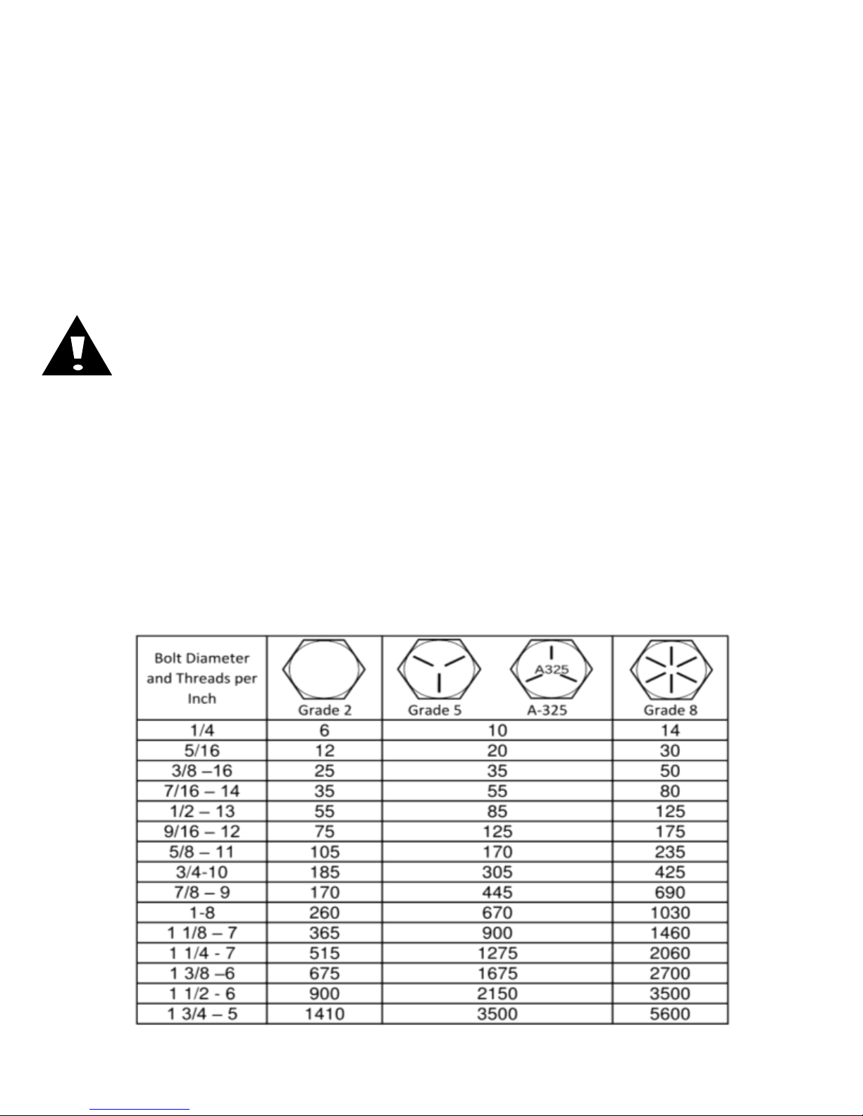
BOLT TORQUE
Important: Over-tightening hardware can cause just as much damage as under-tightening.
Tightening hardware beyond the recommended range can reduce its shock load capacity.
All hardware is either Grade 5 unless otherwise noted. Grade 5 cap screws are marked with three radial
lines on the head. Grade 8 cap screws are marked with six radial lines on the head. If hardware must be
replaced, be sure to replace it with hardware of equal size, strength and thread type. Refer to the torque
values chart when tightening hardware.
The chart below is a guide for proper torque. Use it unless a specified torque is called out elsewhere in
the manual. Torque is the force applied to the end of the handle or cheater bar, times the length of the
handle or bar. Tightening hardware beyond the recommended range can reduce its shock load capacity.
Use a torque wrench wherever possible
The following table shows torque in ft.-lbs. for coarse thread hardware.
2
TABLE OF CONTENTS

FOREWORD
WARRANTY
Yetter Manufacturing warrants all products manufactured and sold by it against defects in material.
This warranty being expressly limited to replacement at the factory of such parts or products as shall
appear to be defective after inspection. This warranty does not obligate the Company to bear cost
of labor in replacement of parts. It is the policy of the Company to make improvements without
incurring obligations to add them to any unit already sold. No warranty is made or authorized to be
made, other than herein set forth. This warranty is in effect for one year after purchase.
DEALER: ________________________________________
Yetter Manufacturing warrants its own products only and cannot be responsible for damages
to equipment on which mounted.
You’ve just joined an exclusive but rapidly
growing club.
For our part, we want to welcome you to the
group and thank you for buying a Yetter product.
We hope your new Yetter products will help you
achieve both goals-increase your productivity and
increase your efficiency so that you may generate
more profit.
This operator’s manual has been designed into
four major sections: Foreword, Safety
Precautions, Installation Instructions and Parts
Breakdown.
This SAFETY ALERT SYMBOL indicates
important safety messages in the manual.
When you see this symbol, be alert to the
possibility of PERSONAL INJURY and
carefully read the message that follows.
The word NOTE is used to convey information
that is out of context with the manual text. It
contains special information such as
specifications, techniques and reference
information of a supplementary nature.
The word IMPORTANT is used in the text when
immediate damage will occur to the machine due
to improper technique or operation.
3
Important will apply to the same information as
specified by note only of an immediate and
urgent nature.
It is the responsibility of the user to read the
operator’s manual and comply with the safe and
correct operating procedure and to lubricate and
maintain the product according to the
maintenance schedule in the operator’s manual.
The user is responsible for inspecting his
machine and for having parts repaired or
replaced when continued use of the product
would cause damage or excessive wear to the
other parts.
It is the user’s responsibility to deliver his
machine to the Yetter dealer who sold him the
product for service or replacement of defective
parts, which are covered by the warranty policy.
If you are unable to understand or follow the
instructions provided in this publication, consult
your local Yetter dealer or contact:
YETTER MANUFACTURING CO.
309/776-4111
800/447-5777
309/776-3222 (FAX)
Website: www.yetterco.com
E-mail: info@yetterco.com

BE ALERT!
YOUR SAFETY IS INVOLVED
WATCH FOR THIS SYMBOL. IT POINTS OUT IMPORTANT SAFETY
PRECAUTIONS. IT MEANS “ATTENTION – BE ALERT!”
It is your responsibility as an owner, operator, or supervision to know and instruct
everyone using this machine at the time of initial assignment and at least annually
thereafter, of the proper operation, precautions, and work hazards which exist in the
operation of the machine in accordance with OSHA regulations.
Safety Is No Accident
The following safety instructions, combined with
common sense, will save your equipment from needless
damage and the operator from unnecessary exposure
to personal hazard. Pay special attention to the
caution notes in the text. Review this manual at least once a year with all
operators.
1. Read and understand the operator’s manual before operating this machine. Failure to do so is
considered a misuse of the equipment.
2. Make sure equipment is secure before operating.
3. Always keep children away from equipment when operating.
4. Make sure everyone that is not directly involved with the operation is out of the work area before
beginning operation.
5. Make sure all safety devices, shields, and guards are in place and functional before beginning
operation
6. Shut off all power to adjust, service, or clean.
7. Keep hands, feet, and clothing away from moving parts. It is a good idea to remove all jewelry
before operating.
8. Inspect the machine periodically during operation for signs of excessive wear, loose fasteners,
and unusual noises.
4
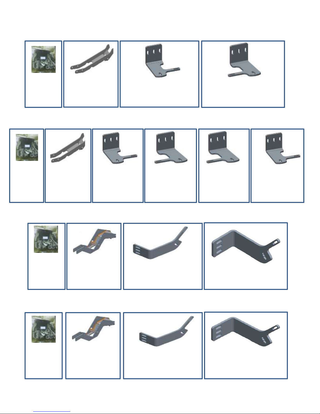
2968-050 Pictorial Parts List
2968-150
QTY 1
Bolt Bag
2968-227
QTY 1
Close Wheel Mount
ONLY IF –LH ORDERED
2968-359-LH
QTY 1
Short Fert. Wheel Mount, LH
ONLY IF –RH ORDERED
2968-359-RH
QTY 1
2968-149
QTY 1
Bolt Bag
2968-227
QTY 1
Close Wheel
Mount
ONLY IF –L ORDERED
2968-359-LH
QTY 1
Short Fert.
Wheel Mount, LH
ONLY IF –L ORDERED
2968-360-RH
QTY 1
Tall Fert.
Wheel Mount, RH
2968-113
QTY 1
Bolt Bag
2968-226
QTY 1
Close Wheel Mount
2968-384
QTY 1
Short Fert. Wheel Mount, LH
2968-385
QTY 1
Short Fert. Wheel Mount, RH
2968-113
QTY 1
Bolt Bag
2968-226
QTY 1
Close Wheel Mount
ONLY IF –LH ORDERED
2968-384
QTY 1
Short Fert. Wheel Mount, LH
ONLY IF –RH ORDERED
2968-385
QTY 1
Short Fert. Wheel Mount, RH
ONLY IF –R ORDERED
2968-359-RH
QTY 1
Short Fert.
Wheel Mount, RH
ONLY IF –R ORDERED
2968-360-LH
QTY 1
Tall Fert.
Wheel Mount, LH
For CNH 2000 Row Units, Single Disc, Left or Right Hand
2968-051-L & 2968-051-R Pictorial Parts List
For CNH 2000 Row Units, Dual Disc
2968-052 Pictorial Parts List
For CNH 1200 Row Units, Single Disc, Left or Right Hand
2968-053 Pictorial Parts List
For CNH 1200 Row Units, Dual Disc
5

2968-054 Pictorial Parts List
2502-807
QTY 8
M16X2X80 Bolt
2520-477
QTY 1
M16X2 Hex Nut
2968-374
QTY 2
Box Mount Bracket
2968-375
QTY 4
Box Mount Spacer
2505-207
QTY 4
5/16 X 1 ¼
Carriage Bolt
2520-206
QTY 4
5/16 Flange
Lock Nut
2570-740
QTY 1
Flanged D-Bolt
5/8 X 2.812 GR 8
2965-128
QTY 1
Hub & Bearing
Assembly, 4 bolt
2965-352
QTY 1
Hub Cap
Casting
2968-320
QTY 1
10” Notched
Blade
2968-364
QTY 1
11” Notched
Blade
2505-207
QTY 4
5/16 X 1 ¼
Carriage Bolt
2520-206
QTY 4
5/16 Flange
Lock Nut
2570-740
QTY 1
Flanged D-Bolt
5/8 X 2.812 GR 8
2965-128
QTY 1
Hub & Bearing
Assembly, 4 bolt
2965-352
QTY 1
Hub Cap
Casting
Box Mount Kit For CNH 1200 Row Units, Dual Disc
2968-132 Pictorial Parts List – 10” Fertilizer Wheel Assembly
2968-133 Pictorial Parts List – 11” Fertilizer Wheel Assembly
6
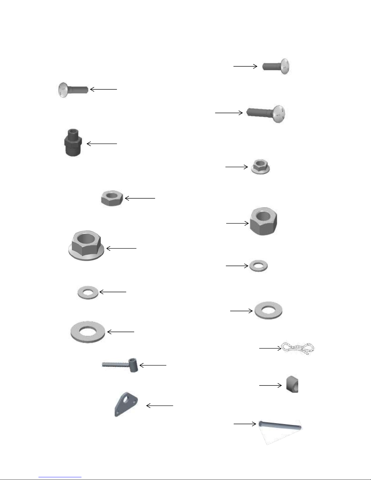
2968-113 Pictorial Parts List
2505-207 – 5/16 – 18 X 1 ¾ CARRIAGE BOLT – QTY 4
2505-208 – 5/16 – 18 X 1 ½ CARRIAGE BOLT – QTY 4
2505-345 – ½ – 13 X 2 CARRIAGE BOLT – QTY 3
2520-206 – 5/16 FLANGE LOCK NUT – QTY 8
2968-386 – TRIANGULAR MOUNT – QTY 2
2984-497 – AIR CYLINDER ROD PIN – QTY 1
2968-218 - INJECTOR HOLDER W.A. – QTY 1
2570-448 - .120 BOWTIE LOCKING COTTER ZP – QTY - 1
2526-454 - 5/8 SAE FLATWASHER HRD'ND ZP – QTY 1
2526-355 – ½ FLAT WASHER HRD'ND ZP – QTY 3
2526-253 – 3/8 SAE FLAT WASHER ZP – QTY 2
2525-251 -3/8 MED. LOCKWASHER ZP – QTY 1
2520-464 -5/8-11 WHIZLOCK ZP, GR 8– QTY 1
2520-357 1/2-13 LOCK HEX NUT, GR A, ZP– QTY 3
2520-253 3/8 JAM HEX NUT – QTY 2
2515-846 -MALE CONNECTOR - 3/8 X 1/4 NPTF– QTY 1
Bolt Bag for 2968-052
7
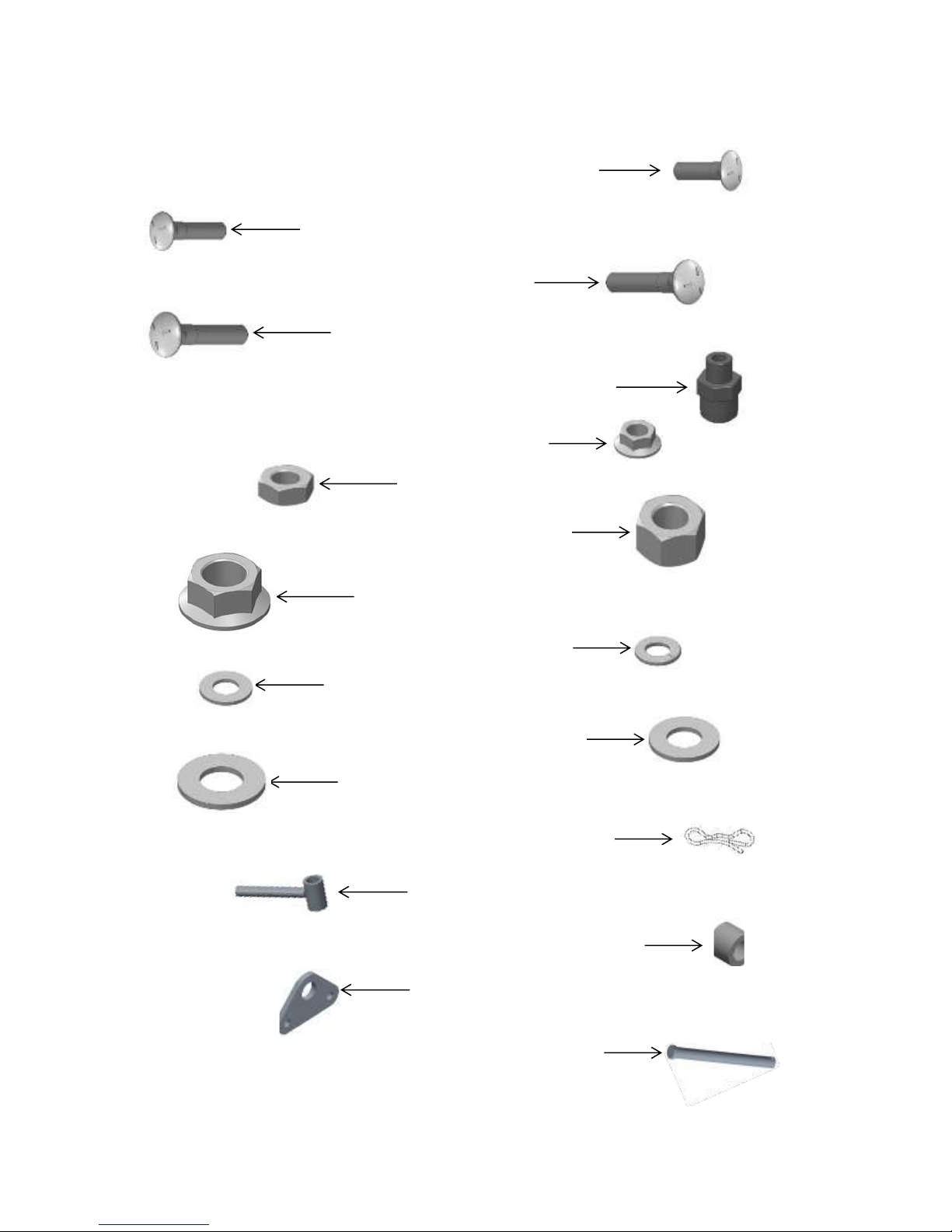
2968-114 Pictorial Parts List
2505-207 – 5/16 – 18 X 1 ¾ CARRIAGE BOLT – QTY 4
2505-208 – 5/16 – 18 X 1 ½ CARRIAGE BOLT – QTY 4
2505-345 – ½ – 13 X 2 CARRIAGE BOLT – QTY 3
2520-206 – 5/16 FLANGE LOCK NUT – QTY 8
2968-386 – TRIANGULAR MOUNT – QTY 2
2984-497 – AIR CYLINDER ROD PIN – QTY 1
2968-218 - INJECTOR HOLDER W.A. – QTY 2
2570-448 - .120 BOWTIE LOCKING COTTER ZP – QTY - 1
2526-454 - 5/8SAE FLATWASHER HRD'ND ZP – QTY 2
2526-355 – ½ FLAT WASHER HRD'ND ZP – QTY 3
2526-253 – 3/8 SAE FLAT WASHER ZP – QTY 4
2525-251 -3/8 MED. LOCKWASHER ZP – QTY 2
2520-464 -5/8-11 WHIZLOCK ZP, GR 8– QTY 2
2520-357 1/2-13 LOCK HEX NUT, GR A, ZP– QTY 3
2520-253 3/8 JAM HEX NUT – QTY 4
2515-846 -MALE CONNECTOR - 3/8 X 1/4 NPTF– QTY 2
2505-343 – ½ – 13 X 2 ½ CARRIAGE BOLT – QTY 3
Bolt Bag for 2968-053
8

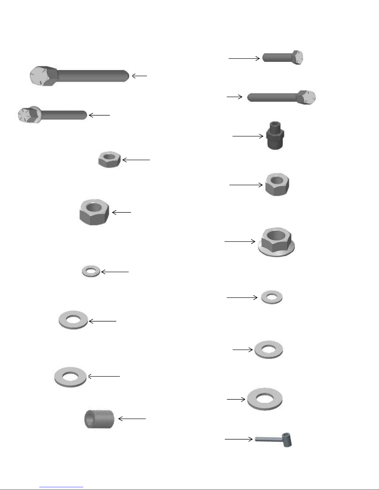
2968-149 Pictorial Parts List – Bolt Bag for 2968-051
2502-314 – 1/2-13 X 2-1/4" HHCS GR 5 ZYD – QTY 3
2502-333 –5/8 – 11 X 9 HHCS GR 5 ZP – QTY 1
2502-373 – ½ – 13 X 6 HHCS GR 5 ZP – QTY 1
2502-808 – M16 X 40MM SERRATED HEX FLANGE ZP – QTY 4
2520-357 1/2-13 LOCK HEX NUT, GR A, ZP– QTY 4
2520-459 5/8 – 11 LOCK HEX NUT GR A ZP – QTY – 1
2526-351 – ½ STANDARD FLAT WASHER ZP – QTY – 5
2526-451 - 5/8 STANDARD FLATWASHER ZP – QTY 2
2967-567 – PIVOT BUSHING – QTY – 2
2526-454 - 5/8SAE FLATWASHER HRD'ND ZP – QTY 2
2526-355 – ½ FLAT WASHER HRD'ND ZP – QTY 5
2526-253 – 3/8 SAE FLAT WASHER ZP – QTY 4
2525-251 -3/8 MED. LOCKWASHER ZP – QTY 2
2520-464 -5/8-11 WHIZLOCK ZP, GR 8– QTY 2
2520-253 3/8 JAM HEX NUT – QTY 4
2515-846 -MALE CONNECTOR - 3/8 X 1/4 NPTF– QTY 2
2968-218 - INJECTOR HOLDER W.A. – QTY 2
9
2502-317 – 1/2-13 X 1 ¾" HHCS GR 5 ZYD – QTY 3
2502-333 –5/8 – 11 X 9 HHCS GR 5 ZP – QTY 1
2502-373 – ½ – 13 X 6 HHCS GR 5 ZP – QTY 1
2502-808 – M16 X 40MM SERRATED HEX FLANGE ZP – QTY 4
2520-357 1/2-13 LOCK HEX NUT, GR A, ZP– QTY 4
2520-459 5/8 – 11 LOCK HEX NUT GR A ZP – QTY – 1
2526-351 – ½ STANDARD FLAT WASHER ZP – QTY – 5
2526-451 - 5/8 STANDARD FLATWASHER ZP – QTY 2
2967-567 – PIVOT BUSHING – QTY – 2
2526-454 - 5/8SAE FLATWASHER HRD'ND ZP – QTY 1
2526-355 – ½ FLAT WASHER HRD'ND ZP – QTY 5
2526-253 – 3/8 SAE FLAT WASHER ZP – QTY 2
2525-251 -3/8 MED. LOCKWASHER ZP – QTY 1
2520-464 -5/8-11 WHIZLOCK ZP, GR 8– QTY 1
2520-253 3/8 JAM HEX NUT – QTY 2
2515-846 -MALE CONNECTOR - 3/8 X 1/4 NPTF– QTY 1
2968-218 - INJECTOR HOLDER W.A. – QTY 1
2968-150 Pictorial Parts List – Bolt Bag for 2968-050
10
 Loading...