

Page 1

YETTER MANUFACTURING CO.
FOUNDED 1930
Colchester, IL 62326-0358
Toll free: 800/447-5777
309/776-3222 (Fax)
Website: www.yetterco.com
E-mail: info@yetterco.com
ROW UNIT MID-MOUNT
FERTILIZER INJECTION OPENER
MODELS 2968-020A, 2968-021A, 2968-026, & 2968-027 SINGLE WHEEL
MODELS 2968-040, 2968-041, 2968-044, & 2968-045 DUAL WHEEL
John Deere, Kinze, & Harvest International Row Units
SET UP & PARTS MANUAL
2565-951_REV_C – 03/2019
Page 2
FOREWORD …………………………………………………...….…............... 3
SAFETY …………………………………………………………...….................. 4
PICTORIAL PART LIST ………………………………….................... 5 – 13
INSTALLATION …………………………………………………....…..... 14 – 19
OPERATION .....………………..…………………......................... 19 – 20
MAINTENANCE …………………………….......………................. 21 – 23
PARTS IDENTIFICATION………………………………...…............ 24 – 37
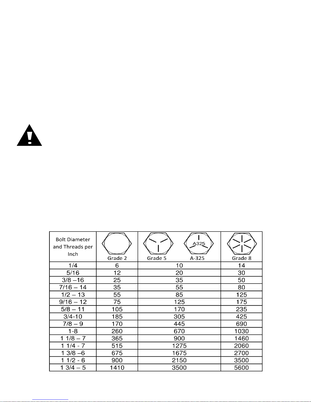
BOLT TORQUE
Important: Over-tightening hardware can cause just as much damage as under-tightening.
Tightening hardware beyond the recommended range can reduce its shock load capacity.
All hardware is either Grade 5 unless otherwise noted. Grade 5 cap screws are marked
with three radial lines on the head. Grade 8 cap screws are marked with six radial lines on the
head. If hardware must be replaced, be sure to replace it with hardware of equal size, strength
and thread type. Refer to the torque values chart when tightening hardware.
The chart below is a guide for proper torque. Use it unless a specified torque is called out
elsewhere in the manual. Torque is the force applied to the end of the handle or cheater bar,
times the length of the handle or bar. Tightening hardware beyond the recommended range can
reduce its shock load capacity.
Use a torque wrench wherever possible
The following table shows torque in ft.-lbs. for coarse thread hardware.
TABLE OF CONTENTS
2
Page 3

FOREWORD
WARRANTY
Yetter Manufacturing warrants all products manufactured and sold by it against defects in material.
This warranty being expressly limited to replacement at the factory of such parts or products as shall
appear to be defective after inspection. This warranty does not obligate the Company to bear cost
of labor in replacement of parts. It is the policy of the Company to make improvements without
incurring obligations to add them to any unit already sold. No warranty is made or authorized to be
made, other than herein set forth. This warranty is in effect for one year after purchase.
DEALER: ________________________________________
Yetter Manufacturing warrants its own products only and cannot be responsible for damages
to equipment on which mounted.
You’ve just joined an exclusive but rapidly
growing club.
For our part, we want to welcome you to the
group and thank you for buying a Yetter product.
We hope your new Yetter products will help you
achieve both goals-increase your productivity and
increase your efficiency so that you may generate
more profit.
This operator’s manual has been designed into
four major sections: Foreword, Safety
Precautions, Installation Instructions and Parts
Breakdown.
This SAFETY ALERT SYMBOL indicates
important safety messages in the manual.
When you see this symbol, be alert to the
possibility of PERSONAL INJURY and
carefully read the message that follows.
The word NOTE is used to convey information
that is out of context with the manual text. It
contains special information such as
specifications, techniques and reference
information of a supplementary nature.
The word IMPORTANT is used in the text when
immediate damage will occur to the machine due
to improper technique or operation.
3
Important will apply to the same information as
specified by note only of an immediate and
urgent nature.
It is the responsibility of the user to read the
operator’s manual and comply with the safe and
correct operating procedure and to lubricate and
maintain the product according to the
maintenance schedule in the operator’s manual.
The user is responsible for inspecting his
machine and for having parts repaired or
replaced when continued use of the product
would cause damage or excessive wear to the
other parts.
It is the user’s responsibility to deliver his
machine to the Yetter dealer who sold him the
product for service or replacement of defective
parts, which are covered by the warranty policy.
If you are unable to understand or follow the
instructions provided in this publication, consult
your local Yetter dealer or contact:
YETTER MANUFACTURING CO.
309/776-4111
800/447-5777
309/776-3222 (FAX)
Website: www.yetterco.com
E-mail: info@yetterco.com
Page 4

BE ALERT!
YOUR SAFETY IS INVOLVED
WATCH FOR THIS SYMBOL. IT POINTS OUT IMPORTANT SAFETY
PRECAUTIONS. IT MEANS “ATTENTION – BE ALERT!”
It is your responsibility as an owner, operator, or supervision to know and instruct
everyone using this machine at the time of initial assignment and at least annually
thereafter, of the proper operation, precautions, and work hazards which exist in the
operation of the machine in accordance with OSHA regulations.
Safety Is No Accident
The following safety instructions, combined with common sense, will save your
equipment from needless damage and the operator from unnecessary exposure
to personal hazard. Pay special attention to the caution notes in the text. Review
this manual at least once a year with all operators.
1. Read and understand the operator’s manual before operating this machine. Failure to do so is
considered a misuse of the equipment.
2. Make sure equipment is secure before operating.
3. Always keep children away from equipment when operating.
4. Make sure everyone that is not directly involved with the operation is out of the work area
before beginning operation.
5. Make sure all safety devices, shields, and guards are in place and functional before beginning
operation
6. Shut off all power to adjust, service, or clean.
7. Keep hands, feet, and clothing away from moving parts. It is a good idea to remove all jewelry
before operating.
8. Inspect the machine periodically during operation for signs of excessive wear, loose fasteners,
and unusual noises.
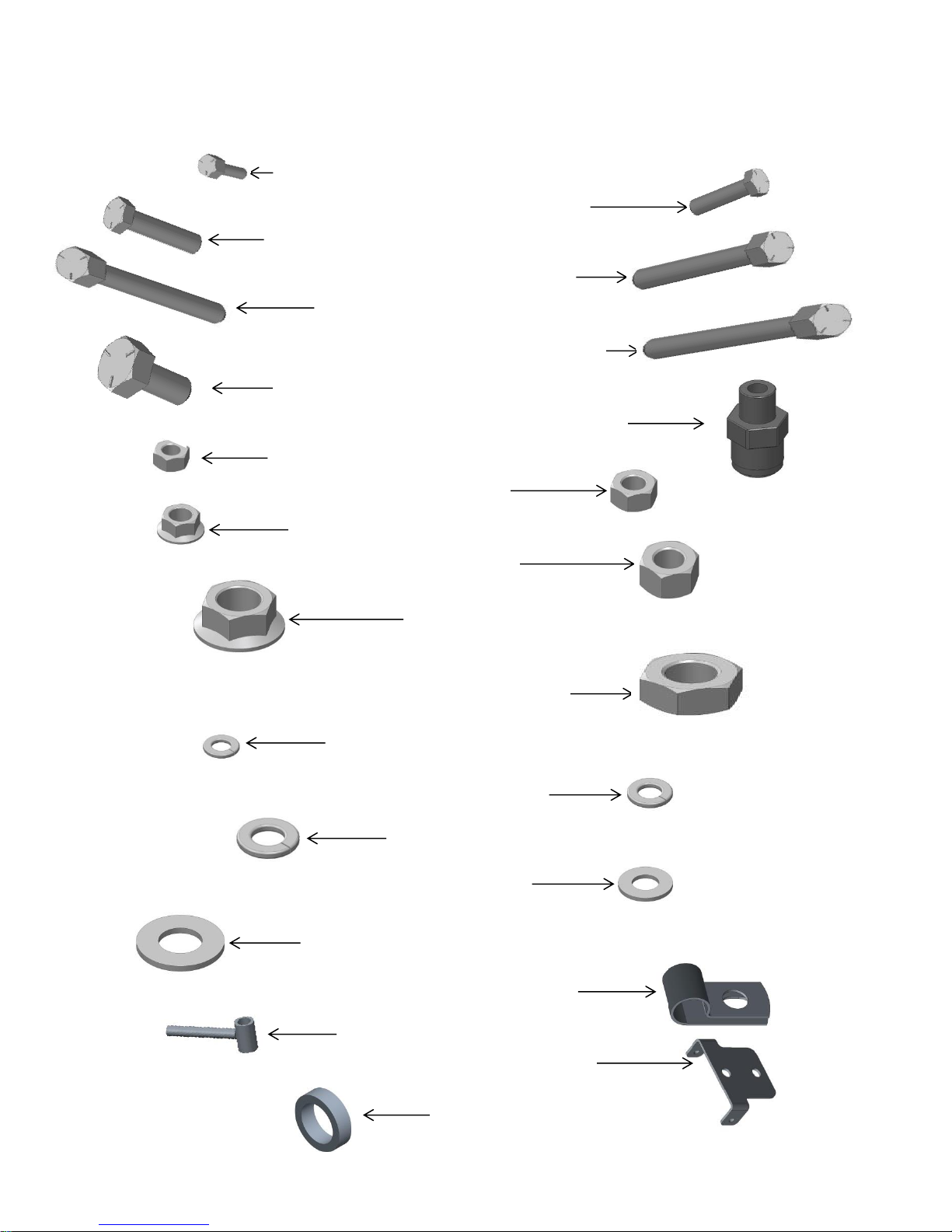
BEFORE BEGINNING INSTALLATION, PLEASE GO THROUGH YOUR ORDER TO
ENSURE THAT YOU HAVE THE CORRECT PARTS AND HARDWARE, AND THAT THE
QUANTITIES ARE CORRECT. USE THE PICTORIAL PART LIST BELOW TO GUIDE YOU.
4
Page 5
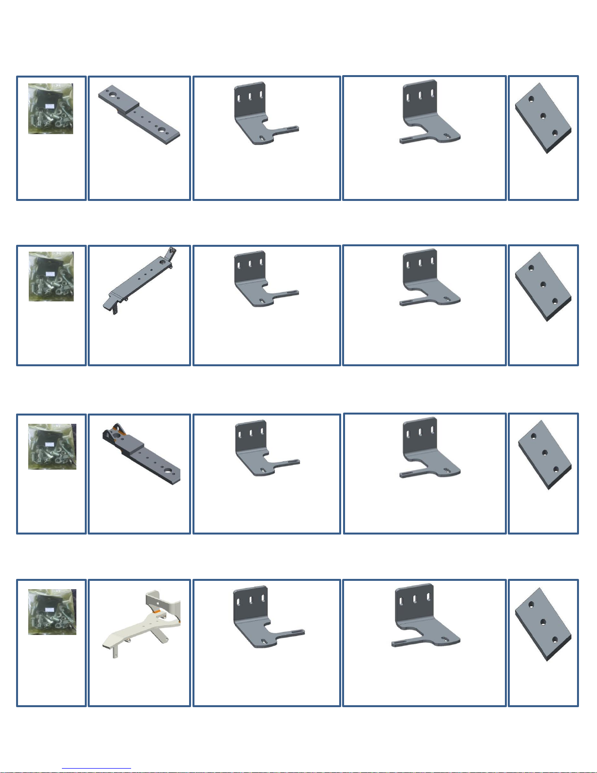
For JD 1700, 7200, & 7300 Single Disc, Left or Right Hand
2968-140
QTY 1
Bolt Bag
2968-222
QTY 1
Close Wheel Mount
Only if –LH Ordered
2968-359-LH
QTY 1
Short Fert. Wheel Mount, LH
Only if –RH Ordered
2968-359-RH
QTY 1
2968-361
QTY 1
Arm Clamp
2968-148
QTY 1
Bolt Bag
2968-223
QTY 1
Close Wheel Mount
Only if –LH Ordered
2968-359-LH
QTY 1
Short Fert. Wheel Mount, LH
Only if –RH Ordered
2968-359-RH
QTY 1
Short Fert. Wheel Mount, RH
2968-361
QTY 1
Arm Clamp
2968-140
QTY 1
Bolt Bag
2968-225
QTY 1
Close Wheel Mount
Only if –LH Ordered
2968-359-LH
QTY 1
Short Fert. Wheel Mount, LH
Only if –RH Ordered
2968-359-RH
QTY 1
Short Fert. Wheel Mount, RH
2968-361
QTY 1
Arm Clamp
2968-152
QTY 1
Bolt Bag
2968-228
QTY 1
Close Wheel Mount
Only if –LH Ordered
2968-359-LH
QTY 1
Short Fert. Wheel Mount, LH
Only if –RH Ordered
2968-359-RH
QTY 1
Short Fert. Wheel Mount, RH
2968-361
QTY 2
Arm Clamp
2968-361
QTY 1
Arm Clamp
2968-021A Pictorial Parts List
For JD 7000 & 7100, Kinze 2000 & 3000, Single Disc, Left or Right Hand
2968-020A Pictorial Parts List
2968-026 Pictorial Parts List
For Harvest International Single Disc, Left or Right Hand
2968-027 Pictorial Parts List
For Kinze 4900 Single Disc, Left or Right Hand
5
Page 6
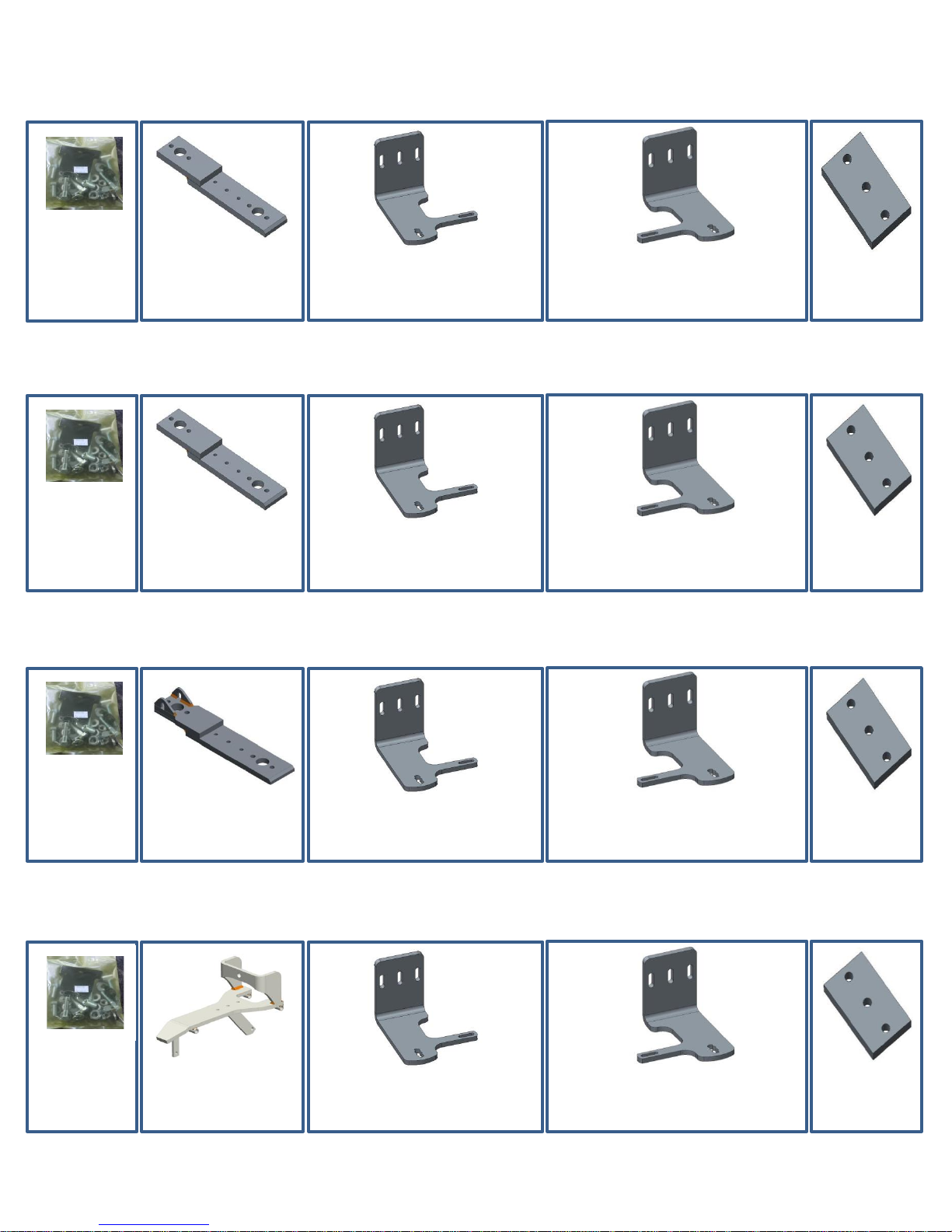
2968-040 Pictorial Parts List
2968-145
QTY 1
Bolt Bag
2968-222
QTY 1
Close Wheel Mount
2968-359-RH
QTY 1
Short Fert. Wheel Mount, RH
2968-360
QTY 1
Tall Fert. Wheel Mount
2968-361
QTY 1
Arm Clamp
2968-147
QTY 1
Bolt Bag
2968-223
QTY 1
Close Wheel Mount
2968-359-RH
QTY 1
Short Fert. Wheel Mount, RH
2968-360
QTY 1
Tall Fert. Wheel Mount
2968-361
QTY 1
Arm Clamp
2968-145
QTY 1
Bolt Bag
2968-225
QTY 1
Close Wheel Mount
2968-359-RH
QTY 1
Short Fert. Wheel Mount, RH
2968-360
QTY 1
Tall Fert. Wheel Mount
2968-361
QTY 1
Arm Clamp
2968-151
QTY 1
Bolt Bag
2968-228
QTY 1
Close Wheel Mount
2968-359-RH
QTY 1
Short Fert. Wheel Mount, RH
2968-360
QTY 1
Tall Fert. Wheel Mount
2968-361
QTY 1
Arm Clamp
For JD 1700, 7200, & 7300 Dual Disc
2968-041 Pictorial Parts List
For JD 7000 & 7100, Kinze 2000 & 3000, Dual Disc
2968-044 Pictorial Parts List
For Harvest International, Dual Disc
2968-045 Pictorial Parts List
For Kinze 4900, Dual Disc
6
Page 7
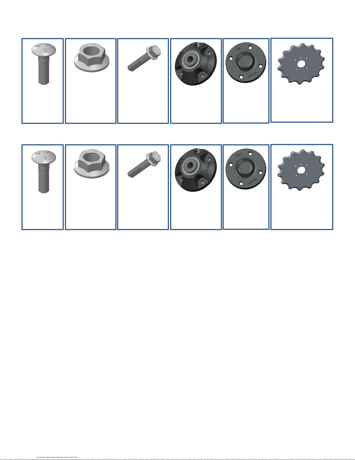
2968-132 Pictorial Parts List – 10” Fertilizer Wheel Assembly
2505-207
QTY 4
5/16 X 1 ¼
Carriage Bolt
2520-206
QTY 4
5/16 Flange
Lock Nut
2570-740
QTY 1
Flanged D-Bolt
5/8 X 2.812 GR 8
2965-128
QTY 1
Hub & Bearing
Assembly, 4 bolt
2965-352
QTY 1
Hub Cap
Casting
2968-320
QTY 1
10” Notched
Blade
2505-207
QTY 4
5/16 X 1 ¼
Carriage Bolt
2520-206
QTY 4
5/16 Flange
Lock Nut
2570-740
QTY 1
Flanged D-Bolt
5/8 X 2.812 GR 8
2965-128
QTY 1
Hub & Bearing
Assembly, 4 bolt
2965-352
QTY 1
Hub Cap
Casting
2968-364
QTY 1
11” Notched
Blade
2968-133 Pictorial Parts List – 11” Fertilizer Wheel Assembly
7
Page 8
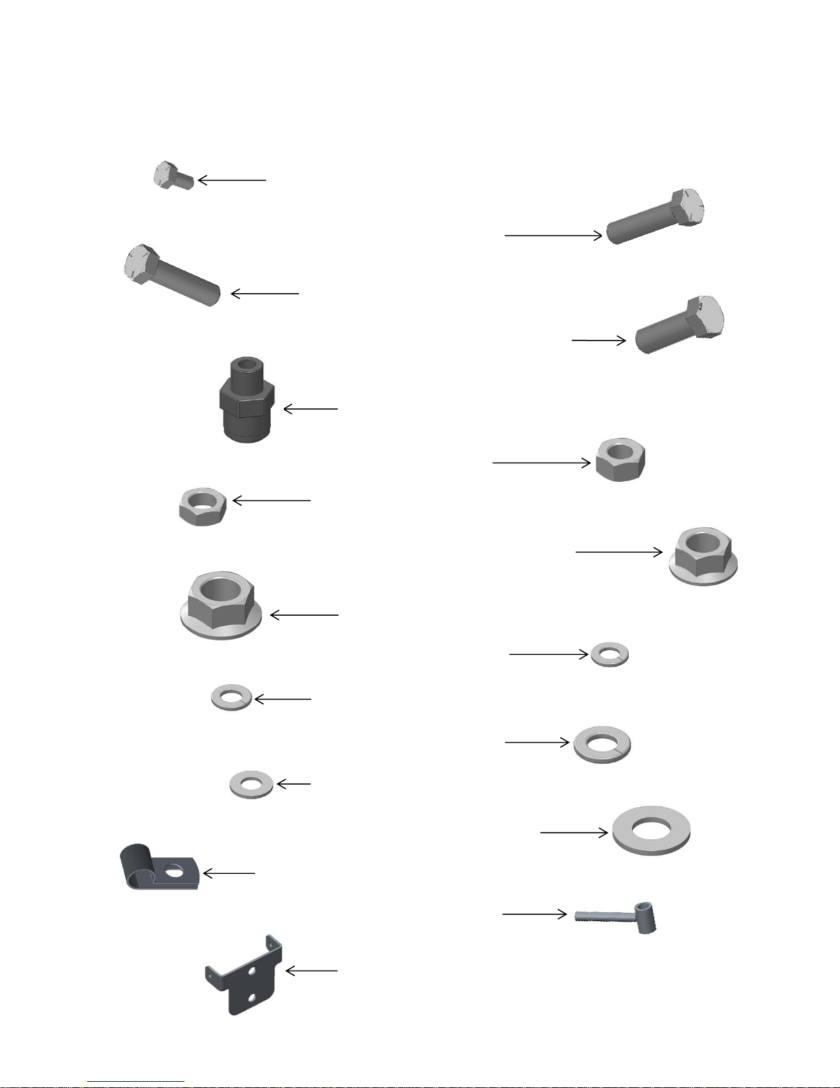
2968-140 Pictorial Parts List – Bolt Bag for 2968-020A & 2968-026
2502-104 -1/4-20 X 1/2 HHCS GR. 5 ZYD.– QTY 2
2502-351 -1/2-13 X 2 HHCS GR.5 ZP– QTY 5
2502-379 -M12 X 1.75 X 35 GRD 10.9 ZYD– QTY 2
2515-846 -MALE CONNECTOR - 3/8 X 1/4 NPTF– QTY 1
2520-151 -1/4-20 HEX NUT, GR 2, ZP– QTY 2
2520-253 -3/8-16 JAM HEX NUT, GR 2, ZP– QTY 2
2520-361 -1/2-13FLANGE WHZLCK HXNT, GR 5, ZP – QTY 2
2520-464 -5/8-11 WHIZLOCK ZP, GR 8– QTY 1
2525-151 - 1/4 MED. LOCKWASHER ZP – QTY 2
2525-251 -3/8 MED. LOCKWASHER ZP – QTY 1
2525-352 - 1/2 MED LOCKWASHER ZP – QTY 5
2526-253 - 3/8 SAE FLATWASHER ZP – QTY 2
2526-454 - 5/8SAE FLATWASHER HRD'ND ZP – QTY 1
2570-724 - 3/8 HOSE P-CLIP W/ VINYL CUSHION – QTY 1
2968-218 - INJECTOR HOLDER W.A. – QTY 1
2968-363 - HOSE HOLDER, FORMED – QTY 1
2502-293 – ½ - 13 X 1 ¼ HHCS GR. 5 ZYD.– QTY 2
8
Page 9
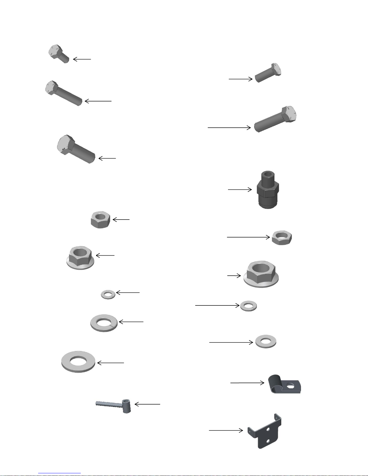
2968-145 Pictorial Parts List – Bolt Bag for 2968-040A & 2968-044
2502-104 -1/4-20 X 1/2 HHCS GR. 5 ZYD.– QTY 2
2502-351 -1/2-13 X 2 HHCS GR.5 ZP– QTY 2
2502-379 -M12 X 1.75 X 35 GRD 10.9 ZYD– QTY 2
2515-846 -MALE CONNECTOR - 3/8 X 1/4 NPTF– QTY 2
2520-151 -1/4-20 HEX NUT, GR 2, ZP– QTY 2
2520-253 -3/8-16 JAM HEX NUT, GR 2, ZP– QTY 4
2520-361 -1/2-13FLANGE WHZLCK HXNT, GR 5, ZP – QTY 2
2520-464 -5/8-11 WHIZLOCK ZP, GR 8– QTY 2
2525-151 - 1/4 MED. LOCKWASHER ZP – QTY 2
2525-251 -3/8 MED. LOCKWASHER ZP – QTY 2
2525-352 - 1/2 MED LOCKWASHER ZP – QTY 5
2502-314 -1/2-13 X 2-1/4" GRADE 5 HHCS ZYD – QTY 3
2526-454 - 5/8SAE FLATWASHER HRD'ND ZP – QTY 3
2570-724 - 3/8 HOSE P-CLIP W/ VINYL CUSHION – QTY 2
2968-218 - INJECTOR HOLDER W.A. – QTY 2
2968-363 - HOSE HOLDER, FORMED – QTY 1
2526-253 - 3/8 SAE FLATWASHER ZP – QTY 4
2502-293 -1/2-13 X 1 ¼” GRADE 5 HHCS ZYD – QTY 2
9
Page 10
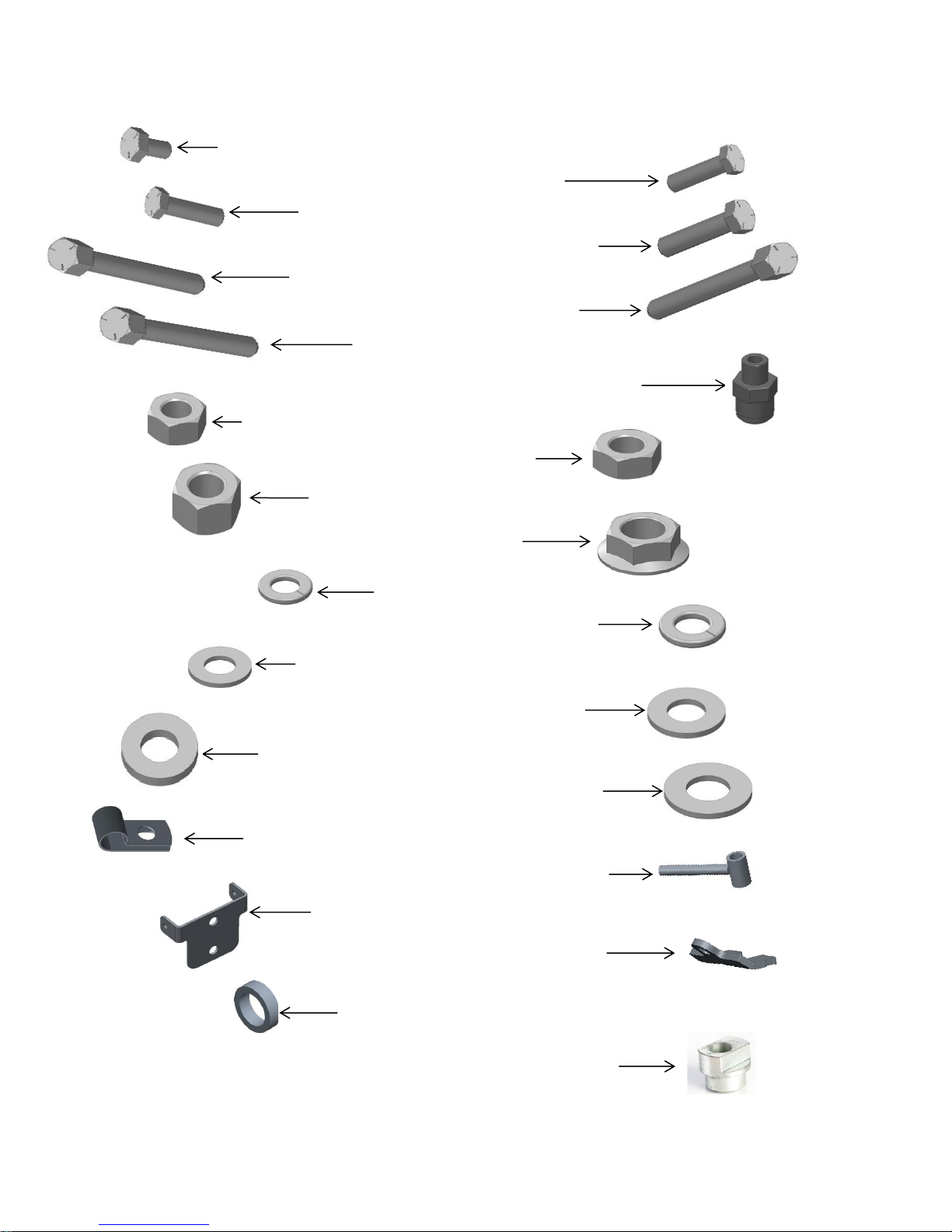
2968-147 Pictorial Parts List – Bolt Bag for 2968-041
2502-104 -1/4-20 X 1/2 HHCS GR. 5 ZYD – QTY 2
2502-245 - 3/8-16 X 1 ¾ HHCS GR 5 ZP – QTY 1
2502-362 -1/2-13 X 5 HHCS GR. 5 ZP – QTY 1
2515-846 -MALE CONNECTOR - 3/8 X 1/4 NPTF– QTY 2
2520-151 -1/4-20 HEX NUT, GR 2, ZP– QTY 2
2502-368 -1/2-13 X 5-1/2 HHCS GR5 ZP – QTY 1
2502-372 -1/2-13 X 6-1/2 HHCS GR5 ZP – QTY 1
2520-357 1/2-13 LOCK HEX NUT, GR A, ZP– QTY 2
2525-251 -3/8 MED. LOCKWASHER ZP – QTY 2
2525-352 - 1/2 MED LOCKWASHER ZP – QTY 3
2502-314 -1/2-13 X 2-1/4" GRADE 5 HHCS ZYD – QTY 3
2520-253 3/8 JAM HEX NUT – QTY 4
2520-464 5/8 WHIZ LOCK– QTY 2
2526-454 - 5/8SAE FLATWASHER HRD'ND ZP – QTY 2
2570-724 - 3/8 HOSE P-CLIP W/ VINYL CUSHION – QTY 2
2526-253 - 3/8 SAE FLATWASHER ZP – QTY 8
2526-352 - 1/2 SAE FLATWASHER ZP – QTY 4
2968-218 - INJECTOR HOLDER W.A. – QTY 2
2968-363 - HOSE HOLDER, FORMED – QTY 1
2968-370 – GAUGE WHEEL ARM STOP – QTY 1
6000-523 – ECCENTRIC BUSHING CLOSE WHEEL– QTY 2
2968-373 – SPACER – QTY 2
2526-402 – 9/16ID X 1 3/4OD X 1/4MB ZP – QTY 2
2502-232 – 3/8-16 X 1 ½ HHCS GR 5 ZP – QTY – 1
10
Page 11
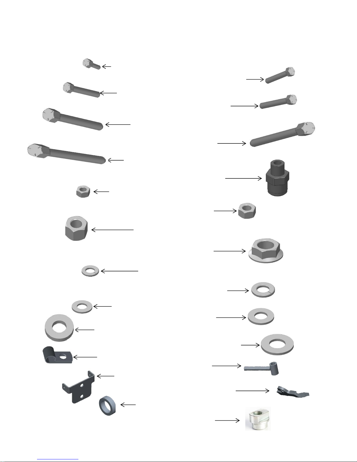
2502-104 -1/4-20 X 1/2 HHCS GR. 5 ZYD.– QTY 1
2502-232 – 3/8 – 16 X 1 ½ HHCS GR 5 ZP – QTY 1
2502-362 -1/2-13 X 5 HHCS GR. 5 ZP – QTY 1
2515-846 -MALE CONNECTOR - 3/8 X 1/4 NPTF– QTY 1
2520-151 -1/4-20 HEX NUT, GR 2, ZP– QTY 1
2502-368 -1/2-13 X 5-1/2 HHCS GR5 ZP – QTY 1
2502-372 -1/2-13 X 6-1/2 HHCS GR5 ZP – QTY 1
2520-357 1/2-13 LOCK HEX NUT, GR A, ZP– QTY 2
2525-251 -3/8 MED. LOCKWASHER ZP – QTY 1
2525-352 - 1/2 MED LOCKWASHER ZP – QTY 3
2502-245 - 3/8-16 X 1-3/4 HHCS GR 5 ZP – QTY 1
2520-253 3/8 JAM HEX NUT – QTY 2
2520-464 5/8 WHIZ LOCK– QTY 1
2526-454 - 5/8 SAE FLATWASHER HRD'ND ZP – QTY 1
2570-724 - 3/8 HOSE P-CLIP W/ VINYL CUSHION – QTY 1
2968-218 - INJECTOR HOLDER W.A. – QTY 1
2526-253 - 3/8 SAE FLATWASHER ZP – QTY 6
2526-352 - 1/2 SAE FLATWASHER ZP – QTY 4
2968-363 - HOSE HOLDER, FORMED – QTY 1
2968-370 – GAUGE WHEEL ARM STOP – QTY 1
2502-351 -1/2-13 X 2" GRADE 5 HHCS – QTY 3
2968-373 – SPACER – QTY 2
2526-402 – 9/16ID X 1 3/4OD X 1/4MB ZP – QTY 2
2968-148 Pictorial Parts List – Bolt Bag for 2968-021A
11
Page 12
2502-104 -1/4-20 X 1/2 HHCS GR. 5 ZYD.– QTY 2
2502-266 – 7/16 – 14 X 1 ½ HHCS GR 5 ZP – QTY 1
2502-368 -1/2-13 X 5-1/2 HHCS GR5 ZP – QTY 1
2515-846 -MALE CONNECTOR - 3/8 X 1/4 NPTF– QTY 2
2520-151 -1/4-20 HEX NUT, GR 2, ZP– QTY 2
2502-372 -1/2-13 X 6-1/2 HHCS GR5 ZP – QTY 1
2502-375 – ½ - 13 X 8 ½ HHCS GR 5 ZP – QTY 1
2520-357 1/2-13 LOCK HEX NUT, GR A, ZP– QTY 2
2525-251 -3/8 MED. LOCKWASHER ZP – QTY 2
2525-352 - 1/2 MED LOCKWASHER ZP – QTY 3
2502-314 -1/2-13 X 2 ¼” GRADE 5 HHCS – QTY 3
2520-253 3/8 JAM HEX NUT – QTY 4
2520-464 5/8 WHIZ LOCK– QTY 2
2526-454 - 5/8 SAE FLATWASHER HRD'ND ZP – QTY 2
2570-724 - 3/8 HOSE P-CLIP W/ VINYL CUSHION – QTY 2
2968-218 - INJECTOR HOLDER W.A. – QTY 2
2526-253 - 3/8 SAE FLATWASHER ZP – QTY 4
2968-363 - HOSE HOLDER, FORMED – QTY 1
2968-373 – SPACER – QTY 2
2520-502 – ¾ - 10 HEX JAM NUT GR 2 ZP– QTY 1
2520-307 – 7/16 – 14 FLANGE WHIZ LOCK GR 2 – QTY 1
2502-501 – ¾ - 10 X 1 ½ HHCS GR 5 ZP – QTY 1
2525-151 – ¼ MED LOCK WASHER ZP – QTY 2
2968-151 Pictorial Parts List – Bolt Bag for 2968-045
12
Page 13

2968-152 Pictorial Parts List – Bolt Bag for 2968-027
2502-104 -1/4-20 X 1/2 HHCS GR. 5 ZYD.– QTY 1
2502-266 – 7/16 – 14 X 1 ½ HHCS GR 5 ZP – QTY 1
2502-368 -1/2-13 X 5-1/2 HHCS GR5 ZP – QTY 1
2515-846 -MALE CONNECTOR - 3/8 X 1/4 NPTF– QTY 1
2520-151 -1/4-20 HEX NUT, GR 2, ZP– QTY 1
2502-372 -1/2-13 X 6-1/2 HHCS GR5 ZP – QTY 1
2502-375 – ½ - 13 X 8 ½ HHCS GR 5 ZP – QYT 1
2520-357 1/2-13 LOCK HEX NUT, GR A, ZP– QTY 2
2525-251 -3/8 MED. LOCKWASHER ZP – QTY 1
2525-352 - 1/2 MED LOCKWASHER ZP – QTY 3
2502-351 -1/2-13 X 2” GRADE 5 HHCS – QTY 3
2520-253 3/8 JAM HEX NUT – QTY 2
2520-464 5/8 WHIZ LOCK– QTY 1
2526-454 - 5/8 SAE FLATWASHER HRD'ND ZP – QTY 1
2570-724 - 3/8 HOSE P-CLIP W/ VINYL CUSHION – QTY 1
2968-218 - INJECTOR HOLDER W.A. – QTY 1
2526-253 - 3/8 SAE FLATWASHER ZP – QTY 2
2968-363 - HOSE HOLDER, FORMED – QTY 1
2968-373 – SPACER – QTY 2
2520-502 – ¾ - 10 HEX JAM NUT GR 2 ZP– QTY 1
2520-307 – 7/16 – 14 FLANGE WHIZ LOCK GR 2 – QTY 1
2502-501 – ¾ - 10 X 1 ½ HHCS GR 5 ZP – QTY 1
2525-251 -3/8 MED. LOCKWASHER ZP – QTY 1
13
Page 14

INSTALLATION INSTRUCTIONS
Step 1: Remove the V-Closing Wheel Tail Piece from the row unit.
JD 1700/7200/7300 Kinze/JD 7000/7100 Harvest International
Step 2: Install the Fertilizer Mount Plate for the Yetter 2968 unit.
JD 1700/7200/7300 Kinze 2000 & 3000/JD 7000/7100
Harvest International Kinze 4900
14
Page 15

INSTALLATION INSTRUCTIONS
Step 3: Attach V-Closing Wheel Tail Piece to the Fertilizer Mount Plate. Reattach the spring.
JD 1700/7200/7300 All Kinze/JD 7000/7100 Harvest International
(2968-020A, 2968-021A, 2968-026A, & 2968-027A MODELS, SINGLE DISC)
(IF INSTALLING 2968-040, 2968-041, 2968-044, OR 2968-045 DUAL DISC, SKIP TO 4B)
Step 4A: Install the 2968-359-LH or 2968-359-RH L-Mount bracket, Arm Clamp, & Formed Hose Holder to the
Fertilizer Mount Plate using 3) ½” X 2” Bolts & 3) ½” Lock Washers.
NOTE: DO NOT tighten the 3) ½” X 2” Bolts until after the wheel are installed.
JD 1700/7200/7300 Kinze/JD 7000/7100
Harvest International Kinze 4900
15
Page 16

INSTALLATION INSTRUCTIONS
(2968-040A, 2968-041A, 2968-044A, & 2968-045 MODELS, DUAL DISC)
Step 4B: Install the 2968-359-RH L-Mount bracket, 2968-360 Tall L-Mount Bracket, Arm Clamp, &
Formed Hose Holder to Fertilizer Mount Plate using 3) ½” X 2 ¼” Bolts & 3) ½” Lock Washers.
NOTE: DO NOT tighten the 3) ½” X 2 ¼” Bolts until after the wheel are installed.
JD 1700/7200/7300 Kinze/JD 7000/7100
Harvest International Kinze 4900
16
Page 17

INSTALLATION INSTRUCTIONS
NOTE: If installing 2968-090 Rear Knife Option, use that manual to finish installation from this point.
Step 5: Place a 5/8 flat washer over the D-bolt & install the Fertilizer Wheel Assembly to the
Fertilizer Wheel Mount Plate & tighten 5/8flange whiz lock nut. See page 19 to determine
which D-bolt hole to install the wheel assembly to achieve your desired depth.
SINGLE WHEEL (RH Shown) DUAL WHEEL
Step 6: Set each Fertilizer Wheel Assembly to the desired spacing off the row (2” – 3”) & then
tighten the 3) ½” bolts from STEP 4.
SINGLE WHEEL DUAL WHEEL WHEEL ADJUSTMENT
17
Page 18

INSTALLATION INSTRUCTIONS
STEP 7: Install each P-Clip to the Formed Hose Holder using ¼” X ½” bolts, ¼” lock washers, & ¼” hex nuts. A
P-Clip should be placed on the side with blade for single wheel placement & on both sides for dual wheel
placement.
SINGLE WHEEL DUAL WHEEL
STEP 8: Install each Injector Holder behind each blade. Thread a 3/8” hex jam nut on the threaded rod roughly 2”,
place a 3/8” lock washer & 3/8” flat washer over the threaded rod against the hex jam nut. Slide the
threaded rod through the horizontal slotted hole on the fertilizer wheel mount so that the threaded rod
end is on the outside of the fertilizer wheel mount. Place a 3/8” flat washer over the end & thread another
3/8” hex jam nut. Before tightening, center the coupler behind the blade & point the bottom of the
coupler slightly forward. Install the push connect fitting on the top side of the coupler if you wish to use it.
18
Page 19

INSTALLATION INSTRUCTIONS
POSITION
DEPTH (USING 10” NOTCHED BLADE)
1
¾” BELOW DOUBLE DISC OPENERS
2
½” BELOW DOUBLE DISC OPENERS
3
¼” BELOW DOUBLE DISC OPENERS
4
EVEN WITH DOUBLE DISC OPENERS
5
¼” ABOVE DOUBLE DISC OPENERS
POSITION
DEPTH (USING 11” NOTCHED BLADE)
1
1 ¼” BELOW DOUBLE DISC OPENERS
2
1” BELOW DOUBLE DISC OPENERS
3
¾” BELOW DOUBLE DISC OPENERS
4
½” BELOW DOUBLE DISC OPENERS
5
¼” BELOW DOUBLE DISC OPENERS
- On dual fertilizer placement, the wheels are staggered front to back
to keep the soil from heaving.
- Fertilizer can be placed 2” – 3” off the seed furrow. Please see your
agronomist to determine best spacing on the rate that’s being applied.
- Blade replacement is necessary when the depth cannot be achieved or
the blade struggles to penetrate the ground.
- If there is buildup of damp soil on the planter gauge wheels or opener disks,
then conditions are less than ideal & some problems may also be
encountered with the fertilizer wheel.
- Seed depth will need rechecked after fertilizer unit installation.
- More row unit down force will be needed to maintain fertilizer wheel depth.
STEP 9: Assemble nozzle tip (not supplied) to each 2968-218 injector holder. Injector tips can be ordered through
fertilizer equipment dealer. Calibrate the fertilizer pump and tips to maximum recommended pressure
of 30PSI and minimum 20PSI at the tip. Attach the fertilizer hose to the top side of each coupler.
OPERATION
19
Page 20

OPERATION
TIP #
LIQUID
PRESSURE IN PSI
CAPACITY 1 NOZZLE
IN GPM
4 MPH
H2O
5 MPH
H20
5.5 MPH
H2O
6 MPH
H2O
7 MPH
H2O
8MPH
H2O
#00015
20
25
30
40
50
60
0.11
0.12
0.13
0.15
0.17
0.18
5.45
5.94
6.44
7.43
8.42
8.91
4.36
4.75
5.15
5.94
6.73
7.13
3.96
4.32
4.68
5.40
6.12
6.48
3.63
3.96
4.29
4.95
5.61
5.94
3.11
3.39
3.68
4.24
4.81
5.09
2.72
2.97
3.22
3.71
4.21
4.46
#0002
20
25
30
40
50
60
0.14
0.16
0.17
0.20
0.23
0.25
6.93
7.92
8.42
9.90
11.39
12.38
5.54
6.34
6.73
7.92
9.11
9.90
5.04
5.76
6.12
7.20
8.28
9.00
4.62
5.28
5.61
6.60
7.59
8.25
3.96
4.53
4.81
5.66
6.51
7.07
3.47
3.96
4.21
4.95
5.69
6.19
#0003
20
25
30
40
50
60
0.21
0.24
0.26
0.30
0.34
0.37
10.40
11.88
12.87
14.85
16.83
18.32
8.32
9.50
10.30
11.88
13.46
14.65
7.56
8.64
9.36
10.80
12.24
13.32
6.93
7.92
8.58
9.90
11.22
12.21
5.94
6.79
7.35
8.49
9.62
10.47
5.20
5.94
6.44
7.43
8.42
9.16
#0004
20
25
30
40
50
60
0.28
0.32
0.35
0.40
0.45
0.49
13.86
15.84
17.33
19.80
22.28
24.26
11.09
12.67
13.86
15.84
17.82
19.40
10.08
11.52
12.60
14.40
16.20
17.64
9.24
10.56
11.55
13.20
14.85
16.17
7.92
9.05
9.90
11.31
12.73
13.86
6.93
7.92
8.66
9.90
11.14
12.13
#0005
20
25
30
40
50
60
0.35
0.40
0.43
0.50
0.56
0.61
17.33
19.80
21.29
24.75
27.72
30.20
13.86
15.84
17.03
19.80
22.18
24.16
12.60
14.40
15.48
18.00
20.16
21.96
11.55
13.20
14.19
16.50
18.48
20.13
9.90
11.31
12.16
14.14
15.84
17.25
8.66
9.90
10.64
12.38
13.86
15.10
#0006
20
25
30
40
50
60
0.42
0.47
0.52
0.60
0.67
0.74
20.79
23.27
25.74
29.70
33.17
36.63
16.63
18.61
20.59
23.76
26.53
29.30
15.12
16.92
18.72
21.60
24.12
26364
13.86
15.51
17.16
19.80
22.11
24.42
11.88
13.29
14.71
16.97
18.95
20.93
10.40
11.63
12.87
14.85
16.58
18.32
#0008
20
25
30
40
50
60
0.57
0.63
0.69
0.80
0.89
0.98
28.22
31.19
34.16
39.60
44.06
48.51
22.57
24.95
27.32
31.68
35.24
38.81
20.52
22.68
24.84
28.80
32.04
35.28
18.81
20.79
22.77
26.40
29.37
32.34
16.12
17.82
19.52
22.63
25.17
27.72
14.11
15.59
17.08
19.80
22.03
24.26
#0010
20
25
30
40
50
60
0.71
0.79
087
1.00
1.12
1.23
35.15
39.11
43.07
49.50
55.44
60.89
28.12
31.28
34.45
39.60
44.35
48.71
25.56
28.44
31.32
36.00
40.32
44.28
23.43
26.07
28.71
33.00
36.96
40.59
20.08
22.35
24.61
28.29
31.68
34.79
17.57
19.55
21.53
24.75
27.72
30.44
#0015
20
25
30
40
50
60
1.06
1.19
1.30
1.50
1.68
1.81
52.47
58.91
64.35
74.25
83.16
89.60
41.98
47.12
51.48
59.40
66.53
71.68
38.16
42.84
46.80
54.00
60.48
65.16
34.98
39.27
42.90
49.50
55.44
59.73
29.98
33.66
36.77
42.43
47.52
51.20
26.24
29.45
32.18
37.13
41.58
44.80
Row Spacing Multiplier
10” X 3.3
15” X 2.0
20” X 1.5
36” X .83
38” X .79
40” X .75
GALLONS PER ACRE (USING WATER)
LIQUID FERTILIZER APPLICATION RATE & PRESSURE CHART – TABLES BASED ON 30” NOZZLE SPACING
20
Page 21

MAINTENANCE
IMPORTANT: If seal is removed from hub/bearing assembly, grease bearing
Every 50 hours. If seal is left assembled, 2-3 pumps of grease twice a year,
depending on acres, is sufficient.
IMPORTANT: For proper operation, the planter frame must operate level
(fore, aft & side to side) and at the correct height, typically 20”-22”.
21
Page 22

MAINTENANCE
Grease must fill this
Hubcap cavity.
NOTE: BE CERTAIN TO ALIGN THE GREASE FITTING WITH THE SLOT IN THE WHEEL & HUBCAP SO THAT THE GREASE
CAN FLOW FREELY.
22
Page 23

MAINTENANCE
PART #
DESCRIPTION
OUNCES OF GREASE
2968-320
10” FERTILIZER WHEEL
1.12 OZ
2968-364
11” FERTILIZER WHEEL
1.12 OZ
CAUTION: To help prevent serious injury/death to you or others caused by unexpected movement, service machine
on a level surface. Lower machine to ground or sufficiently lock or block raised machine before servicing.
If machine is connected to tractor, engage parking brake & place transmission in “PARK”, shut off engine,
& remove key. If machine is detached from tractor, block wheels & use shop stands to prevent movement.
CAUTION: DO NOT CLEAN, LUBRICATE, OR ADJUST MACHINE WHILE IN MOTION
Use grease based on NLGI consistency numbers & the expected air temperature range during the service interval.
Use a multi-purpose polyurea, water resistant, moderate speed, & NLGI grade #2 grease. Other greases may be used
if they meet the following NLGI Perfomance.
IMPORTANT: Some types of grease thickener are not compatible with others. Consult your grease supplier before
mixing different types of greases.
Alternative Lubricants
Conditions in certain geographical areas may require special lubricants & lubrication practices which do not appear in
the operator’s manual. If there are any questions, consult Yetter Manufacturing Co. to obtain latest information &
recommendation.
Storing Lubricants
Your machine can operate at top efficiency only if clean lubricants are used. Use clean containers to handle all
lubricants. Store them in an area protected from dust, moisture and other contaminants
LUBRICATION SYMBOLS
Lubricate with grease at hourly interval indicated on symbol if Lubrication Intervals
seal has been removed. If seal is left installed on hub/beairng
assembly, apply 2 – 3 pumps of grease to each hub twice a
season to keep cavity full.
IMPORTANT: The recommended service intervals are based on normal conditions; severe or unusual conditions may
require more frequent lubrication. Perform each lubrication and service procedure at the beginning
& end of each season. Clean grease fittings before using grease gun, to avoid injecting dirt & grit into
the bearing. Replace any lost or broken fittings immediately. If a fitting fails to take grease, remove &
clean thoroughly, replace fitting if necessary. Also check for failure of adjoining parts.
BEARING REPLACEMENT INSTALLATION
1. When assembling the spoke wheels, bearing assembly and hubcap, be sure to align the grease transfer hole
in the spoke wheel with the groove in the hubcap and hole in the hub to allow grease passage.
2. Assemble the wheels, hubs and caps.
3. Grease the wheel/hub/bearing assembly.
23
Page 24

2968-020A-L-LB PARTS IDENTIFICATION
ITEM
PART #
DESCRIPTION
QTY 1 2502-104
¼ - 20 X ½ HHCS GR 5 ZYD
1
2
2502-351
½ - 13 X 2 HHCS GR 5 ZP
5 3 2502-379
M12 X 1.75 X 35 GRD 10.9 ZYD
2 4 2515-846
MALE CONNECTOR – 3/8 X ¼ NPTF
1 5 2520-151
¼ - 20 HEX NUT ZP
1 6 2520-253
3/8 – 16 JAM HEX NUT ZP
2 7 2520-361
½ - 13 FLANGE WHIZ LOCK HEX NUT, GR 5, ZP
2 8 2520-464
5/8 – 11 WHIZ LOCK HEX NUT, GR 2, ZP
1 9 2525-151
¼ MEDIUM LOCK WASHER ZP
1
10
2525-251
3/8 MEDIUM LOCK WASHER ZP
1
11
2525-352
½ MEDIUM LOCK WASHER ZP
5
12
2526-253
3/8 SAE FLAT WASHER ZP
2
13
2526-454
5/8 SAE FLAT WASHER HARDENED ZP
1
14
2570-724
3/8 HOSE P-CLIP WITH VINYL CUSHION
1
15
2968-218
INJECTOR HOLDER W.A.
1
16
2968-222
FERTILIZER CLOSE WHEEL MOUNT W.A.
1
17
2968-361
ARM CLAMP
1
18
2968-363
FORMED HOSE HOLDER
1
19
2968-359-LH
LH SHORT FERTILIZER WHEEL MOUNT
1
FOR JD 1700, 7200, & 7300
24
Page 25

2968-020A-R-LB PARTS IDENTIFICATION
ITEM
PART #
DESCRIPTION
QTY 1 2502-104
¼ - 20 X ½ HHCS GR 5 ZYD
1 2 2502-351
½ - 13 X 2 HHCS GR 5 ZP
5 3 2502-379
M12 X 1.75 X 35 GRD 10.9 ZYD
2 4 2515-846
MALE CONNECTOR – 3/8 X ¼ NPTF
1 5 2520-151
¼ - 20 HEX NUT ZP
1 6 2520-253
3/8 – 16 JAM HEX NUT ZP
2 7 2520-361
½ - 13 FLANGE WHIZ LOCK HEX NUT, GR 5, ZP
2
8
2520-464
5/8 – 11 WHIZ LOCK HEX NUT, GR 2, ZP
1
9
2525-151
¼ MEDIUM LOCK WASHER ZP
1
10
2525-251
3/8 MEDIUM LOCK WASHER ZP
1
11
2525-352
½ MEDIUM LOCK WASHER ZP
5
12
2526-253
3/8 SAE FLAT WASHER ZP
2
13
2526-454
5/8 SAE FLAT WASHER HARDENED ZP
1
14
2570-724
3/8 HOSE P-CLIP WITH VINYL CUSHION
1
15
2968-218
INJECTOR HOLDER W.A.
1
16
2968-222
FERTILIZER CLOSE WHEEL MOUNT W.A.
1
17
2968-361
ARM CLAMP
1
18
2968-363
FORMED HOSE HOLDER
1
19
2968-359-RH
RH SHORT FERTILIZER WHEEL MOUNT
1
FOR JD 1700, 7200, & 7300
25
Page 26

2968-021A-L-LB PARTS IDENTIFICATION
ITEM
PART #
DESCRIPTION
QTY
1
2502-104
¼ - 20 X ½ HHCS GR 5 ZYD
1 2 2502-232
3/8 – 16 X 1 ½ HHCS GR 5 ZYD (USED ON KINZE 3000)
1
2502-245
3/8 – 16 1 ¾ HHCS GR 5 ZP (USED ON JD 7000 & 7100, KINZE 2000)
1 3 2502-351
½ - 13 X 2 HHCS GR 5 ZP
3
4
2502-362
½ - 13 X 5 HHCS GR 5 ZP
1 5 2502-368
½ - 13 X 5 ½ HHCS GR 5 ZP
1 6 2502-372
½ - 13 X 6 ½ HHCS GR 5 ZP
1 7 2515-846
MALE CONNECTOR – 3/8 X ¼ NPTF
1 8 2520-151
¼ - 20 HEX NUT ZP
1 9 2520-253
3/8 – 16 JAM HEX NUT ZP
2
10
2520-357
½ - 13 LOCK HEX NUT, GR A, ZP
2
11
2520-464
5/8 – 11 WHIZ LOCK HEX NUT, GR 2, ZP
1
12
2525-151
¼ MEDIUM LOCK WASHER ZP
1
13
2525-251
3/8 MEDIUM LOCK WASHER ZP
1
14
2525-352
½ MEDIUM LOCK WASHER ZP
3
15
2526-253
3/8 SAE FLAT WASHER ZP
3
16
2526-352
½ SAE FLAT WASHER ZP
4
17
2526-402
9/16ID X 1 ¾OD X 1/4MB ZP
2
18
2526-454
5/8 SAE FLAT WASHER HARDENED ZP
1
19
2570-724
3/8 HOSE P-CLIP WITH VINYL CUSHION
1
20
2968-218
INJECTOR HOLDER W.A.
1
21
2968-223
FERTILIZER CLOSE WHEEL MOUNT W.A.
1
22
2968-359-LH
LH SHORT FERTILIZER WHEEL MOUNT
1
23
2968-361
ARM CLAMP
1
24
2968-363
FORMED HOSE HOLDER
1
25
2968-370
GAUGE WHEEL ARM STOP(ONLY USED ON JD 7000 & 7100, KINZE 2000)
1
26
2968-373
SPACER
2
27
6000-523
ECCENTRIC BUSHING CLOSE WHEEL
2
FOR JD 7000 & 7100, KINZE 2000 & 3000
26
Page 27

2968-021A-R-LB PARTS IDENTIFICATION
ITEM
PART #
DESCRIPTION
QTY
1
2502-104
¼ - 20 X ½ HHCS GR 5 ZYD
1 2 2502-232
3/8 – 16 X 1 ½ HHCS GR 5 ZYD (USED ON KINZE 3000)
1
2502-245
3/8 – 16 1 ¾ HHCS GR 5 ZP (USED ON JD 7000 & 7100, KINZE 2000)
1 3 2502-351
½ - 13 X 2 HHCS GR 5 ZP
3
4
2502-362
½ - 13 X 5 HHCS GR 5 ZP
1 5 2502-368
½ - 13 X 5 ½ HHCS GR 5 ZP
1 6 2502-372
½ - 13 X 6 ½ HHCS GR 5 ZP
1 7 2515-846
MALE CONNECTOR – 3/8 X ¼ NPTF
1 8 2520-151
¼ - 20 HEX NUT ZP
1 9 2520-253
3/8 – 16 JAM HEX NUT ZP
2
10
2520-357
½ - 13 LOCK HEX NUT, GR A, ZP
2
11
2520-464
5/8 – 11 WHIZ LOCK HEX NUT, GR 2, ZP
1
12
2525-151
¼ MEDIUM LOCK WASHER ZP
1
13
2525-251
3/8 MEDIUM LOCK WASHER ZP
1
14
2525-352
½ MEDIUM LOCK WASHER ZP
3
15
2526-253
3/8 SAE FLAT WASHER ZP
3
16
2526-352
½ SAE FLAT WASHER ZP
4
17
2526-402
9/16ID X 1 ¾OD X 1/4MB ZP
2
18
2526-454
5/8 SAE FLAT WASHER HARDENED ZP
1
19
2570-724
3/8 HOSE P-CLIP WITH VINYL CUSHION
1
20
2968-218
INJECTOR HOLDER W.A.
1
21
2968-223
FERTILIZER CLOSE WHEEL MOUNT W.A.
1
22
2968-361
ARM CLAMP
1
23
2968-363
FORMED HOSE HOLDER
1
24
2968-370
GAUGE WHEEL ARM STOP(ONLY USED ON JD 7000 & 7100, KINZE 2000)
1
25
2968-373
SPACER
2
26
2968-359-RH
RH SHORT FERTILIZER WHEEL MOUNT
1
27
6000-523
ECCENTRIC BUSHING CLOSE WHEEL
2
FOR JD 7000 & 7100, KINZE 2000 & 3000
27
Page 28

2968-026A-L-LB PARTS IDENTIFICATION
ITEM
PART #
DESCRIPTION
QTY 1 2502-104
¼ - 20 X ½ HHCS GR 5 ZYD
1 2 2502-293
½ - 13 X 1 ¼ HHCS GR 5 ZP
2 3 2502-351
½ - 13 X 2 HHCS GR 5 ZP
5 4 2515-846
MALE CONNECTOR – 3/8 X ¼ NPTF
1 5 2520-151
¼ - 20 HEX NUT ZP
1 6 2520-253
3/8 – 16 JAM HEX NUT ZP
2 7 2520-361
½ - 13 FLANGE WHIZ LOCK HEX NUT, GR 5, ZP
2
8
2520-464
5/8 – 11 WHIZ LOCK HEX NUT, GR 2, ZP
1
9
2525-151
¼ MEDIUM LOCK WASHER ZP
1
10
2525-251
3/8 MEDIUM LOCK WASHER ZP
1
11
2525-352
½ MEDIUM LOCK WASHER ZP
5
12
2526-253
3/8 SAE FLAT WASHER ZP
2
13
2526-454
5/8 SAE FLAT WASHER HARDENED ZP
1
14
2570-724
3/8 HOSE P-CLIP WITH VINYL CUSHION
1
15
2968-218
INJECTOR HOLDER W.A.
1
16
2968-225
FERTILIZER CLOSE WHEEL MOUNT W.A., HARVEST INTL
1
17
2968-361
ARM CLAMP
1
18
2968-363
FORMED HOSE HOLDER
1
19
2968-359-LH
LH SHORT FERTILIZER WHEEL MOUNT
1
HARVEST INTERNATIONAL
28
Page 29

2968-026A-R-LB PARTS IDENTIFICATION
ITEM
PART #
DESCRIPTION
QTY 1 2502-104
¼ - 20 X ½ HHCS GR 5 ZYD
1 2 2502-293
½ - 13 X 1 ¼ HHCS GR 5 ZP
2 3 2502-351
½ - 13 X 2 HHCS GR 5 ZP
5 4 2515-846
MALE CONNECTOR – 3/8 X ¼ NPTF
1 5 2520-151
¼ - 20 HEX NUT ZP
1 6 2520-253
3/8 – 16 JAM HEX NUT ZP
2 7 2520-361
½ - 13 FLANGE WHIZ LOCK HEX NUT, GR 5, ZP
2
8
2520-464
5/8 – 11 WHIZ LOCK HEX NUT, GR 2, ZP
1
9
2525-151
¼ MEDIUM LOCK WASHER ZP
1
10
2525-251
3/8 MEDIUM LOCK WASHER ZP
1
11
2525-352
½ MEDIUM LOCK WASHER ZP
5
12
2526-253
3/8 SAE FLAT WASHER ZP
2
13
2526-454
5/8 SAE FLAT WASHER HARDENED ZP
1
14
2570-724
3/8 HOSE P-CLIP WITH VINYL CUSHION
1
15
2968-218
INJECTOR HOLDER W.A.
1
16
2968-225
FERTILIZER CLOSE WHEEL MOUNT W.A., HARVEST INTL
1
17
2968-361
ARM CLAMP
1
18
2968-363
FORMED HOSE HOLDER
1
19
2968-359-RH
RH SHORT FERTILIZER WHEEL MOUNT
1
HARVEST INTERNATIONAL
29
Page 30

2968-027A-L-LB PARTS IDENTIFICATION
ITEM
PART #
DESCRIPTION
QTY
1
2502-104
¼ - 20 X ½ HHCS GR 5 ZYD
1 2 2502-266
7/16 – 14 X 1 ½ HHCS GR 5 ZP
1
3
2502-351
½ - 13 X 2 HHCS GR 5 ZP
3 4 2502-368
½ - 13 X 5 ½ HHCS GR 5 ZP
1
5
2502-372
½ - 13 X 6 ½ HHCS GR 5 ZP
1 6 2502-375
½ - 13 X 8 ½ HHCS GR 5 ZP
1 7 2502-501
¾ - 10 X 1 ½ HHCS GR 5 ZP
1 8 2515-846
MALE CONNECTOR – 3/8 X ¼ NPTF
1 9 2520-151
¼ - 20 HEX NUT ZP
1
10
2520-253
3/8 – 16 JAM HEX NUT ZP
2
11
2520-307
7/16 – 14 FLANGE LOCK NUT
1
12
2520-357
½ - 13 LOCK HEX NUT, GR A, ZP
2
13
2520-464
5/8 – 11 WHIZ LOCK HEX NUT, GR 2, ZP
1
14
2520-502
¾ - 10 HEX JAM NUT, GR 2, ZP
1
15
2525-151
¼ MEDIUM LOCK WASHER ZP
1
16
2525-251
3/8 MEDIUM LOCK WASHER ZP
1
17
2525-352
½ MEDIUM LOCK WASHER ZP
3
18
2526-253
3/8 SAE FLAT WASHER ZP
2
19
2526-454
5/8 SAE FLAT WASHER HARDENED ZP
1
20
2565-179
YETTER DECAL
1
21
2570-724
3/8 HOSE P-CLIP WITH VINYL CUSHION
1
22
2968-218
INJECTOR HOLDER W.A.
1
23
2968-228
FERTILIZER CLOSE WHEEL MOUNT W.A.
1
24
2968-359-LH
LH SHORT FERTILIZER WHEEL MOUNT
1
25
2968-361
ARM CLAMP
1
26
2968-363
FORMED HOSE HOLDER
1
27
2968-373
SPACER
2
KINZE 4900
30
Page 31

2968-027-R-LB PARTS IDENTIFICATION
ITEM
PART #
DESCRIPTION
QTY
1
2502-104
¼ - 20 X ½ HHCS GR 5 ZYD
1 2 2502-266
7/16 – 14 X 1 ½ HHCS GR 5 ZP
1 3 2502-351
½ - 13 X 2 HHCS GR 5 ZP
3 4 2502-368
½ - 13 X 5 ½ HHCS GR 5 ZP
1 5 2502-372
½ - 13 X 6 ½ HHCS GR 5 ZP
1
6
2502-375
½ - 13 X 8 ½ HHCS GR 5 ZP
1 7 2502-501
¾ - 10 X 1 ½ HHCS GR 5 ZP
1 8 2515-846
MALE CONNECTOR – 3/8 X ¼ NPTF
1
9
2520-151
¼ - 20 HEX NUT ZP
1
10
2520-253
3/8 – 16 JAM HEX NUT ZP
2
11
2520-307
7/16 – 14 FLANGE LOCK NUT
1
12
2520-357
½ - 13 LOCK HEX NUT, GR A, ZP
2
13
2520-464
5/8 – 11 WHIZ LOCK HEX NUT, GR 2, ZP
1
14
2520-502
¾ - 10 HEX JAM NUT, GR 2, ZP
1
15
2525-151
¼ MEDIUM LOCK WASHER ZP
1
16
2525-251
3/8 MEDIUM LOCK WASHER ZP
1
17
2525-352
½ MEDIUM LOCK WASHER ZP
3
18
2526-253
3/8 SAE FLAT WASHER ZP
2
19
2526-454
5/8 SAE FLAT WASHER HARDENED ZP
1
20
2565-179
YETTER DECAL
1
21
2570-724
3/8 HOSE P-CLIP WITH VINYL CUSHION
1
22
2968-218
INJECTOR HOLDER W.A.
1
23
2968-228
FERTILIZER CLOSE WHEEL MOUNT W.A.
1
24
2968-359-LH
LH SHORT FERTILIZER WHEEL MOUNT
1
25
2968-361
ARM CLAMP
1
26
2968-363
FORMED HOSE HOLDER
1
27
2968-373
SPACER
2
KINZE 4900
31
Page 32

2968-040-LB PARTS IDENTIFICATION
ITEM
PART #
DESCRIPTION
QTY 1 2502-104
¼ - 20 X ½ HHCS GR 5 ZYD
1
2
2502-314
½ - 13 X 2 ¼ HHCS GR 5 ZP
3 3 2502-351
½ - 13 X 2 HHCS GR 5 ZP
2 4 2502-379
M12 X 1.75 X 35 GRD 10.9 ZYD
2 5 2515-846
MALE CONNECTOR – 3/8 X ¼ NPTF
2 6 2520-151
¼ - 20 HEX NUT ZP
2 7 2520-253
3/8 – 16 JAM HEX NUT ZP
4 8 2520-361
½ - 13 FLANGE WHIZ LOCK HEX NUT, GR 5, ZP
2 9 2520-464
5/8 – 11 WHIZ LOCK HEX NUT, GR 2, ZP
2
10
2525-151
¼ MEDIUM LOCK WASHER ZP
2
11
2525-251
3/8 MEDIUM LOCK WASHER ZP
2
12
2525-352
½ MEDIUM LOCK WASHER ZP
5
13
2526-253
3/8 SAE FLAT WASHER ZP
4
14
2526-454
5/8 SAE FLAT WASHER HARDENED ZP
2
15
2570-724
3/8 HOSE P-CLIP WITH VINYL CUSHION
2
16
2968-218
INJECTOR HOLDER W.A.
2
17
2968-222
FERTILIZER CLOSE WHEEL MOUNT W.A.
2
18
2968-359-RH
RH SHORT FERTILIZER WHEEL MOUNT
1
19
2968-360
TALL FERT. WHEEL MOUNT
1
20
2968-361
ARM CLAMP
1
21
2968-363
FORMED HOSE HOLDER
2
FOR JD 1700, 7200, & 7300
32
Page 33

2968-041-LB PARTS IDENTIFICATION
FOR JD 7000 & 7100, KINZE 2000 & 3000
33
Page 34

2968-041-LB PARTS IDENTIFICATION
ITEM
PART #
DESCRIPTION
QTY 1 2502-104
¼ - 20 X ½ HHCS GR 5 ZYD
2 2 2502-245
3/8 – 16 1 ¾ HHCS GR 5 ZP
1 3 2502-314
½ - 13 X 2 ¼ HHCS GR 5 ZP
3 4 2502-362
½ - 13 X 5 HHCS GR 5 ZP
1 5 2502-368
½ - 13 X 5 ½ HHCS GR 5 ZP
1 6 2502-372
½ - 13 X 6 ½ HHCS GR 5 ZP
1 7 2515-846
MALE CONNECTOR – 3/8 X ¼ NPTF
2 8 2520-151
¼ - 20 HEX NUT ZP
2 9 2520-253
3/8 – 16 JAM HEX NUT ZP
4
10
2520-357
½ - 13 LOCK HEX NUT, GR A, ZP
2
11
2520-464
5/8 – 11 WHIZ LOCK HEX NUT, GR 2, ZP
2
12
2525-151
¼ MEDIUM LOCK WASHER ZP
1
13
2525-251
3/8 MEDIUM LOCK WASHER ZP
2
14
2525-352
½ MEDIUM LOCK WASHER ZP
3
15
2526-253
3/8 SAE FLAT WASHER ZP
5
16
2526-352
½ SAE FLAT WASHER ZP
4
17
2526-402
9/16ID X 1 ¾OD X 1/4MB ZP
2
18
2526-454
5/8 SAE FLAT WASHER HARDENED ZP
1
19
2565-179
YETTER DECAL
2
20
2570-724
3/8 HOSE P-CLIP WITH VINYL CUSHION
1
21
2968-218
INJECTOR HOLDER W.A.
1
22
2968-223
FERTILIZER CLOSE WHEEL MOUNT W.A.
1
23
2968-359-RH
RH SHORT FERTILIZER WHEEL
1
24
2968-360
TALL FERTILIZER WHEEL MOUNT
1
25
2968-361
ARM CLAMP
1
26
2968-363
FORMED HOSE HOLDER
1
27
2968-370
GAUGE WHEEL ARM STOP (ONLY USED ON JD 7000 & 7100, KINZE 2000)
1
28
2968-373
SPACER
2
29
6000-523
ECCENTRIC BUSHING CLOSE WHEEL MOUNT
2
FOR JD 7000 & 7100, KINZE 2000 & 3000
34
Page 35

2968-044-R-LB PARTS IDENTIFICATION
ITEM
PART #
DESCRIPTION
QTY 1 2502-104
¼ - 20 X ½ HHCS GR 5 ZYD
2 2 2502-293
½ - 13 X 1 ¼ HHCS GR 5 ZP
2 3 2502-314
½ - 13 2 ¼ HHCS GR 5 ZP
3 4 2502-351
½ - 13 X 2 HHCS GR 5 ZP
2 5 2515-846
MALE CONNECTOR – 3/8 X ¼ NPTF
2 6 2520-151
¼ - 20 HEX NUT ZP
2 7 2520-253
3/8 – 16 JAM HEX NUT ZP
4
8
2520-361
½ - 13 FLANGE WHIZ LOCK HEX NUT, GR 5, ZP
2
9
2520-464
5/8 – 11 WHIZ LOCK HEX NUT, GR 2, ZP
2
10
2525-151
¼ MEDIUM LOCK WASHER ZP
2
11
2525-251
3/8 MEDIUM LOCK WASHER ZP
2
12
2525-352
½ MEDIUM LOCK WASHER ZP
5
13
2526-253
3/8 SAE FLAT WASHER ZP
4
14
2526-454
5/8 SAE FLAT WASHER HARDENED ZP
2
15
2570-724
3/8 HOSE P-CLIP WITH VINYL CUSHION
2
16
2968-218
INJECTOR HOLDER W.A.
2
17
2968-225
FERTILIZER CLOSE WHEEL MOUNT W.A., HARVEST INTL
1
18
2968-360
TALL FERTILIZER WHEEL MOUNT
1
19
2968-361
ARM CLAMP
1
20
2968-363
FORMED HOSE HOLDER
1
21
2968-359-RH
RH SHORT FERTILIZER WHEEL MOUNT
1
HARVEST INTERNATIONAL
35
Page 36

2968-045-LB PARTS IDENTIFICATION
ITEM
PART #
DESCRIPTION
QTY
1
2502-104
¼ - 20 X ½ HHCS GR 5 ZYD
1 2 2502-266
7/16 – 14 X 1 ½ HHCS GR 5 ZP
1
3
2502-351
½ - 13 X 2 HHCS GR 5 ZP
3 4 2502-368
½ - 13 X 5 ½ HHCS GR 5 ZP
1
5
2502-372
½ - 13 X 6 ½ HHCS GR 5 ZP
1 6 2502-375
½ - 13 X 8 ½ HHCS GR 5 ZP
1 7 2502-501
¾ - 10 X 1 ½ HHCS GR 5 ZP
1 8 2515-846
MALE CONNECTOR – 3/8 X ¼ NPTF
1 9 2520-151
¼ - 20 HEX NUT ZP
1
10
2520-253
3/8 – 16 JAM HEX NUT ZP
2
11
2520-307
7/16 – 14 FLANGE LOCK NUT
1
12
2520-357
½ - 13 LOCK HEX NUT, GR A, ZP
2
13
2520-464
5/8 – 11 WHIZ LOCK HEX NUT, GR 2, ZP
1
14
2520-502
¾ - 10 HEX JAM NUT, GR 2, ZP
1
15
2525-151
¼ MEDIUM LOCK WASHER ZP
1
16
2525-251
3/8 MEDIUM LOCK WASHER ZP
1
17
2525-352
½ MEDIUM LOCK WASHER ZP
3
18
2526-253
3/8 SAE FLAT WASHER ZP
2
19
2526-454
5/8 SAE FLAT WASHER HARDENED ZP
1
20
2565-179
YETTER DECAL
1
21
2570-724
3/8 HOSE P-CLIP WITH VINYL CUSHION
1
22
2968-218
INJECTOR HOLDER W.A.
1
23
2968-228
FERTILIZER CLOSE WHEEL MOUNT W.A.
1
24
2968-359-LH
LH SHORT FERTILIZER WHEEL MOUNT
1
25
2968-360
TALL FERTILIZER WHEEL MOUNT
1
26
2968-361
ARM CLAMP
1
27
2968-363
FORMED HOSE HOLDER
1
28
2968-373
SPACER
2
KINZE 4900
36
Page 37

PARTS IDENTIFICATION
ITEM
PART #
DESCRIPTION
QTY
1
2505-207
5/16 – 18 X 1 ¼ CARRIAGE BOLT GR 5 ZP
4 2 2520-206
5/16 – 18 FLANGE LOCK NUT
4 3 2570-740
D-BOLT, FLANGED, 5/8 – 11 X 2.812 GR 8
1 4 2965-128
HUB & BEARING, 4 BOLT
1 5 2965-352
HUB CAP, 4 BOLT, BLACK
1
6
2968-320
10.05 X .256 FERTILIZER WHEEL (SHOWN)
1 2968-364
11.05 X .256 FERTILIZER WHEEL
1
ITEM
PART #
DESCRIPTION
QTY
1
2550-069
TRIPLE LIP SEAL, NTI# 1812-5
1 2 2570-594
BEARING, 2 ROW
1
3
2570-715
BEARING INSERT
1
4
2965-351
HUB CASTING, MACHINED, 4 BOLT
1
5
2533-110
¼ - 28 SELF-TAP ZERK, STRAIGHT
1
2968-132 (SHOWN) 10” WHEEL ASSEMBLY
2968-133 11” WHEEL ASSEMBLY
37
Page 38

38
Page 39

39
Page 40

2565-951_REV_C – 03/2019
40
 Loading...