

Page 1

FLOATING RESIDUE MANAGER
INSTRUCTION MANUAL
PARTS IDENTIFICATION
2565-415_REV_A – UPDATED 03/09
YETTER MANUFACTURING CO.
FOUNDED 1930
Colchester, IL 62326-0358
Toll free: 800/447-5777
309/776-3222 (Fax)
Website: www.yetterco.com
E-mail: info@yetterco.com
1
Page 2

FOREWORD
You’ve just joined an exclusive but rapidly growing
club.
For our part, we want to welcome you to the group
and thank you for buying a Yetter product.
We hope your new Yetter products will help you
achieve both goals-increase your productivity and
increase your efficiency so that you may generate
more profit.
This operator’s manual has been designed into four
major sections: Foreword, Safety Precautions,
Installation Instructions and Parts Breakdown.
This SAFETY ALERT SYMBOL indicates
important safety messages in the manual.
When you see this symbol, be alert to the
possibility of PERSONAL INJURY and carefully
read the message that follows.
The word NOTE is used to convey information that
is out of context with the manual text. It contains
special information such as specifications,
techniques and reference information of a
supplementary nature.
The word IMPORTANT is used in the text when
immediate damage will occur to the machine due to
improper technique or operation. Important will
apply to the same information as specified by note
only of an immediate and urgent nature.
It is the responsibility of the user to read the
operator’s manual and comply with the safe and
correct operating procedure and to lubricate and
maintain the product according to the maintenance
schedule in the operator’s manual.
The user is responsible for inspecting his machine
and for having parts repaired or replaced when
continued use of the product would cause damage
or excessive wear to the other parts.
It is the user’s responsibility to deliver his machine
to the Yetter dealer who sold him the product for
service or replacement of defective parts, which are
covered by the warranty policy.
If you are unable to understand or follow the
instructions provided in this publication, consult
your local Yetter dealer or contact:
YETTER MANUFACTURING CO.
309/776-4111
800/447-5777
309/776-3222 (FAX)
Website: www.yetterco.com
E-mail: info@yetterco.com
WARRANTY
Yetter Manufacturing warrants all products manufactured and sold by it against defects in material. This
warranty being expressly limited to replacement at the factory of such parts or products as shall appear to be
defective after inspection. This warranty does not obligate the Company to bear cost of labor in replacement of
parts. It is the policy of the Company to make improvements without incurring obligations to add them to any
unit already sold. No warranty is made or authorized to be made, other than herein set forth. This warranty is in
effect for one year after purchase.
Dealer __________________________________________________________
Yetter Manufacturing warrants its own products only and cannot be responsible for damages to equipment on
which mounted.
2
Page 3

SAFETY
A brief description of signal words that may be used in this manual:
CAUTION: Used as a general reminder of good safety practices or to direct attention to unsafe
practices.
WARNING: Denotes a specific potential hazard.
DANGER: Denotes the most serious specific potential hazard.
SAFETY PRECAUTIONS
You can make your farm a safer place to live and work if you observe the safety precautions
given. Study these precautions carefully and insist that they be followed by those working with
you and for you.
Finally, remember this: an accident is usually caused by someone’s carelessness, neglect or
oversight.
WARNING
Never clean, lubricate or adjust a machine that is in motion. Always lower or block the implement
before performing service.
If machine must be serviced in the raised position, jack or block it up to prevent it from
accidentally falling and injuring someone.
Do not allow riders on the tractor or implement.
Use speeds and caution dictated by the terrain being traversed. Do not operate on any slope
steep enough to cause tipping or loss of control.
Be sure all personnel are clear of the immediate area before operating.
Read and understand the operator’s manual and require all others persons who will operate the
equipment to do the same.
Be familiar with all tractor and implement controls and be prepared to stop engine and implements
quickly in an emergency.
CAUTION
Consult your implement and tractor operator’s manual for correct and safe operating practices.
Beware of towed implement width and allow safe clearance.
FAILURE TO HEED MAY RESULT IN PERSONAL INJURY OR DEATH.
3
Page 4

ASSEMBLY
2910/2995/2996 MOUNTING BRACKET
1. Remove 3/8 x 2-1/2" roll pin from end of 1-1/2" diameter shank and remove coulter.
2. 2910 Coulter-Bolt the top mount plate to the third set of holes in the mounting bracket with two
1/2 x 1-1/2" bolts, lockwashers and nuts.
2995/2996 Coulter-Bolt the top mount plate to the second set of holes in the mounting bracket
with two 1/2 x 1-1/2" bolts, lockwashers and hex nuts.
3. Slide bracket over pivot casting, reinstall coulter on shank and reinsert roll pin.
4. Install and tighten 5/8" setscrew in lock collar to 110 ft./lb. torque maximum.
5. Attach floating residue manager stem to mounting bracket with two 1/2 x 3-1/2" bolts and lock
hex nuts at desired height.
6. Assemble spoke wheels (2 per row) and attach to floating residue manager stem.
SPOKE WHEEL ASSEMBLY
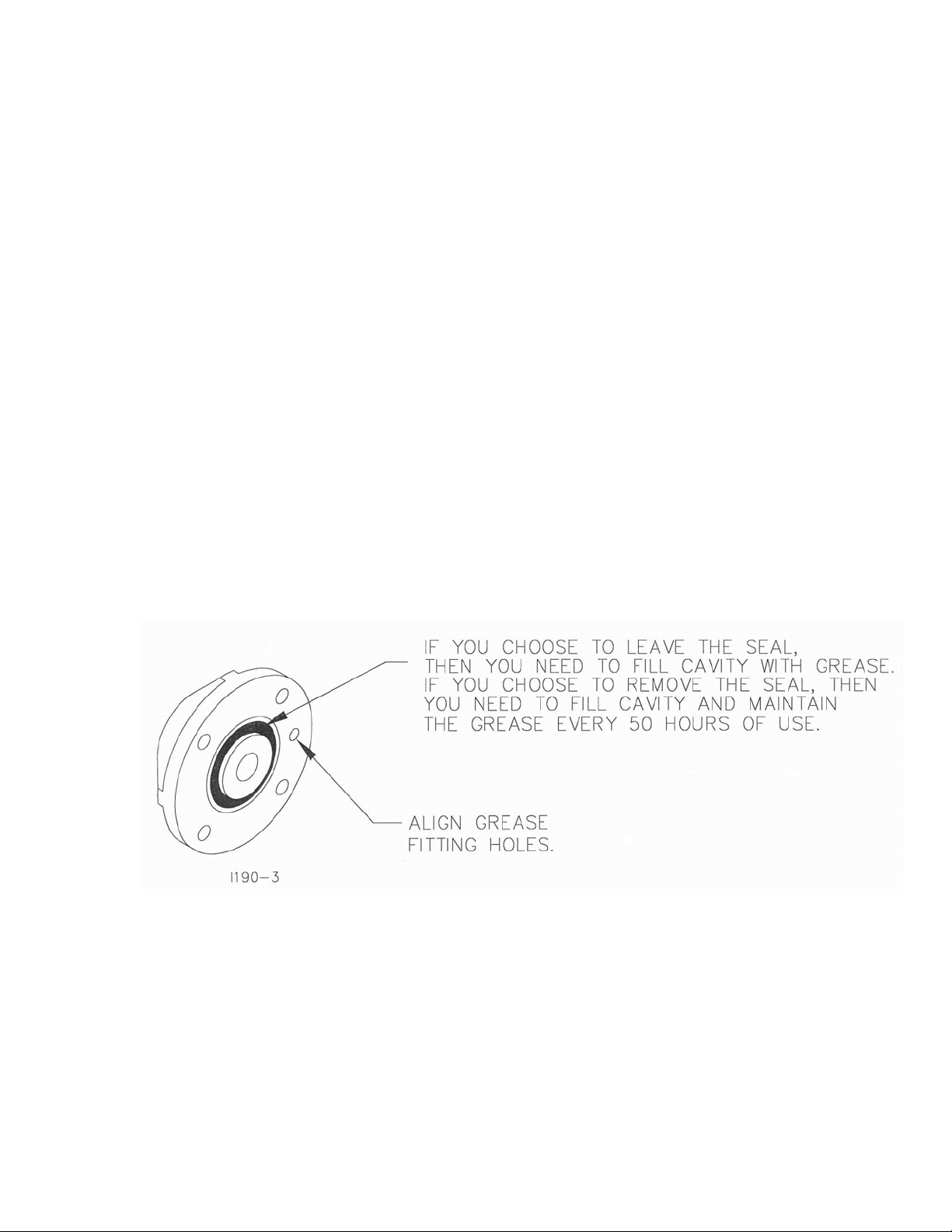
1. Before assembling spoke wheel, bearing
assembly and hub cap, remove the seal
from the exposed side of the bearing in the hub and bearing
assembly if you wish touse the zerk to grease the bearing,
otherwise the bearing is sealed.
2. When assembling spoke wheel, bearing
assembly and hub cap, be sure to align the grease fitting hole with the hole in the spoke
wheel and the groove in hub cap to assure
proper greasing of wheel and hub assembly.
3. Assemble spoke wheel, bearing assembly and hub cap as shown on the parts identification
page. Be sure to install the 11/16" spacers and bearing shields. Stagger spoke wheels so
that half of the rows have a left wheel leading and half of the rows have a right wheel leading.
Torque 150 ft.lbs.
4. Fill hub and bearing with general purpose grease if seal was removed from bearing in step 1.
4
Page 5
MAINTENANCE
BEARING ASSEMBLY AND LUBRICATION
Practice Safety
Understand and practice safe service procedures before doing work. Follow ALL the
operating, maintenance and safety information in the equipment operator manual.
Clear the area of bystanders, especially small children, when performing any
maintenance or adjustments. Keep work area clean and dry. Use adequate lighting
for the job. Use only tools, jacks and hoists of sufficient capacity for the job.
Never lubricate, service, or adjust machine while it is moving. Keep hands, feet, and
clothing from power-driven moving and rotating parts. Disengage all power and
operate controls to relieve pressure. Lower equipment to the ground and stop the
engine. Remove the key. Wait for all moving parts to stop before servicing,
adjusting, repairing or unplugging.
Securely support any machine elements with blocks or safety stands that must be
raised for service work.
Keep all parts in good condition and properly installed. Fix damaged equipment
immediately. Replace worn or broken parts. Remove any buildup of grease, oil, or
debris.
Make sure all guards are in place and properly secured when maintenance work is
completed.
Assembly
5
Page 6

MAINTENANCE
NOTE: Be certain to align the grease fitting with the slot in the wheel and the
hubcap so that the grease can flow freely.
6
IMPORTANT: THE 2527-530 WASHER MUST BE INSTALLED OR THE WHEEL
AND HUB ASSEMBLY WILL FALL OFF DURING USE.
Page 7

MAINTENANCE
Grease must fill this
Hubcap cavity.
7
Page 8

MAINTENANCE
Lubrication
CAUTION: To help prevent serious injury or death to you or others caused
by unexpected movement, service machine on a level surface. Lower
machine to ground or sufficiently lock or block raised machine before
servicing. If machine is connected to tractor, engage parking brake and
place transmission in "PARK", shut off engine and remove key. If machine
is detached from tractor, block wheels and use shop stands to prevent
movement.
CAUTION: Do not clean, lubricate, or adjust machine while in motion.
Use grease based on NLGI consistency numbers and the expected air temperature
range during the service interval.
Use a multi-purpose lithium, water resistant, moderate speed, and NLGI grade
#2 grease.
Other greases may be used if they meet the following NLGI Performance
Classification: GC-LB
IMPORTANT: Some types of grease thickener are not compatible with others.
Consult your grease supplier before mixing different types of grease.
Alternative Lubricants
Conditions in certain geographical areas may require special lubricants and
lubrication practices which do not appear in the operator's manual. If there are any
questions, consult Yetter Manufacturing Co. to obtain latest information and
recommendation.
PART #
2967-404 13” TAPER TOOTH R.M. WHEEL 1.12 OZ
2967-602 13” SHARK TOOTH R.M. WHEEL 1.12 OZ
2967-186 FLOATER WHEEL KIT W/R.M. WHEEL 2.08 OZ
2967-596 HEAVY DUTY OR BEVEL R.M. WHEEL
W/ FLOATER WHEEL KIT
DESCRIPTION
OUNCES OF GREASE
2.40 OZ
Storing Lubricants
Your machine can operate at top efficiency only if clean lubricants are used.
Use clean containers to handle all lubricants.
Store them in an area protected from dust, moisture and other contaminants.
8
Page 9

MAINTENANCE
Lubrication Symbols
Lubricate with grease at hourly interval indicated on symbol.
Lubrication Intervals
IMPORTANT: The recommended service intervals are based on normal
conditions; severe or unusual conditions may require more frequent
lubrication.
Perform each lubrication and service procedure at the beginning and end of each
season.
Clean grease fittings before using grease gun, to avoid injecting dirt and grit into the
bearing. Replace any lost or broken fittings immediately. If a fitting fails to take
grease, remove and clean thoroughly, replace fitting if necessary. Also check for
failure of adjoining parts.
BEARING REPLACEMENT INSTALLATION
1. If you wish to be able to grease the bearings in the hubs, remove the seal
from one side of the bearings as illustrated before assembly. Otherwise the
bearings may be left “sealed for life”.
2. When assembling the spoke wheels, bearing assembly and hubcap, be sure
to align the grease transfer hole in the spoke wheel with the groove in the
hubcap and hole in the hub to allow grease passage.
3. Install/assemble the wheels, hubs and caps. IMPORTANT: THE 2527-530
WASHER MUST BE INSTALLED OR THE WHEEL AND HUB ASSEMBLY
WILL FALL OFF DURING USE.
4. Grease the wheel/hub/bearing assembly.
9
Page 10

MAINTENANCE
Storing the Equipment
Store the machine in an area away from human activity
Store machine in RAISED position.
Install service locks on all wheel cylinders.
At the end of the season, the machine should be thoroughly inspected and prepared
for storage. Repair or replace any worn or damaged components to prevent down
time at the start of the next season. Store machine under cover with all parts in
operating condition.
• Clean machine thoroughly to remove all dirt, debris and crop residue, which
would hold moisture and cause rusting.
• Inspect machine for worn or broken parts. See your Yetter Farm Equipment
dealer during the off-season so that parts or service can be acquired when
machine is not needed in the field.
• Lubricate bearings as outlined in the Lubrication section
• Paint all parts which are chipped or worn and require repainting.
• Store machine in a clean, dry place with the planting unit out of the sun.
• If the machine cannot be stored inside, cover with a waterproof tarpaulin and
tie securely in place.
• Do not allow children to play on or around the machine
10
Page 11

Problem
Overall settings
Cannot set shallow
enough.
Spoke wheels not turning
continuously.
TROUBLESHOOTING
Cause
Planter not set correctly.
Planter not set correctly.
Spoke wheels not
engaging residue.
Solution
Ensure that in operation
the planter frame is at
correct height (20-22")
and level the tool bar.
See above.
Lower wheels to ensure
rotation at all times, DO
NOT engage solid part of
wheel in dirt.
11
Page 12

PARTS IDENTIFICATION
2967-113 - FLOATING RESIDUE MANAGER STEM
Key Qty Part No. Description
1 1 2967-241 Pivot Arm W.A.
2 1 2967-242 Adjustment Tube W.A.
3 1 2967-425 Inside Bushing ZYD
4 1 2502-296 1/2-13 x 2-1/2 HHCS Gr. 5 ZP
5 1 2520-357 1/2-13 Lock Hex Nut ZP
6 1 2960-359 Spring Adjustment Pin ZP
7 1 2570-448 1/8 Std. Hairpin Cotter ZP
8 1 2550-750 Spring, Floating R.M.
OPTIONAL EQUIPMENT
07-97 TO 05-08
12
Page 13

PARTS IDENTIFICATION
2967-113 - FLOATING RESIDUE MANAGER STEM
Key Qty Part No. Description
1 1 2967-241 Pivot Arm W.A.
2 1 2967-242 Adjustment Tube W.A.
3 1 2967-425 Inside Bushing ZYD
4 1 2502-296 1/2-13 x 2-1/2 HHCS Gr. 5 ZP
5 1 2520-357 1/2-13 Lock Hex Nut ZP
6 1 2960-359 Spring Adjustment Pin ZP
7 1 2570-448 1/8 Std. Hairpin Cotter ZP
8 1 2550-750 Spring, Floating R.M
13
05-08 TO PRESENT
Page 14

14
PARTS IDENTIFICATION
07-97 TO 05-08
Page 15

PARTS IDENTIFICATION
05-08 TO PRESENT
15
Page 16

16
PARTS IDENTIFICATION
07-97 TO 05-08
Page 17

PARTS IDENTIFICATION
05-08 TO PRESENT
17
Page 18

PARTS IDENTIFICATION
07-97 TO 05-08
18
Page 19

19
PARTS IDENTIFICATION
05-08 TO PRESENT
Page 20

2565-415_REV_A
03/09
20
 Loading...