

Yetter 2967-029A, 2967-029A-PP, 2967-097A Owner's Manual
YETTER MANUFACTURING CO.
Founded 1930
Colchester, IL 62326
Toll Free: (800)447-5777
Fax: (309)776-3222
Website: yetterco.com
E-mail: info@yetterco.com
TITAN
TM
SERIES
2967-029A / 2967-029A-PP SHORT U.N.T.
2967-097A SHORT U.N.T.
RESIDUE MANAGER
Owner’s Manual
Part Identification
2565-696_Rev_J - 12/2019
TM
CNH
TM
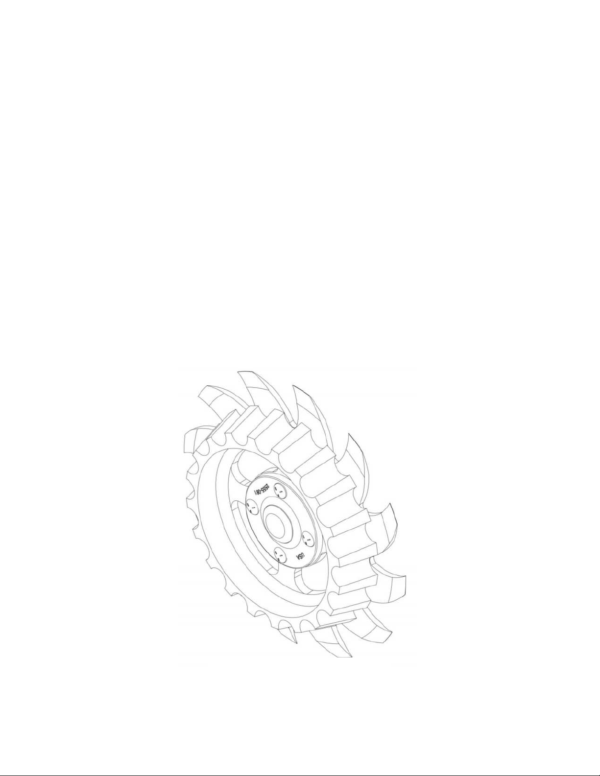
Table of Contents
2967-186 Floater Wheel
LH Assembly Shown
(2) Required Per Row
Optional Equipment
Foreword ..................................................................................................... 3
Warranty ...................................................................................................... 3
Safety ........................................................................................................... 4
Bolt Torque ................................................................................................. 5
Operation ..................................................................................................... 6
Planter Adjustment .................................................................................. 7-8
Installation Instructions ........................................................................ 9-11
Maintenance ................................ ......................................................... 12-16
Part Identification ................................................................................ 17-19
2

FOREWORD
WARRANTY
Yetter Manufacturing warrants all products manufactured and sold by it against defects in material.
This warranty being expressly limited to replacement at the factory of such parts or products as shall
appear to be defective after inspection. This warranty does not obligate the Company to bear cost
of labor in replacement of parts. It is the policy of the Company to make improvements without
incurring obligations to add them to any unit already sold. No warranty is made or authorized to be
made, other than herein set forth. This warranty is in effect for one year after purchase.
DEALER: ________________________________________
Yetter Manufacturing warrants its own products only and cannot be responsible for damages
to equipment on which mounted.
You’ve just joined an exclusive but rapidly
growing club.
For our part, we want to welcome you to the
group and thank you for buying a Yetter product.
We hope your new Yetter products will help you
achieve both goals-increase your productivity
and increase your efficiency so that you may
generate more profit.
This operator’s manual has been designed into
four major sections: Foreword, Safety
Precautions, Installation Instructions and Parts
Breakdown.
This SAFETY ALERT SYMBOL
indicates important safety messages
in the manual. When you see this
symbol, be alert to the possibility of
PERSONAL INJURY and
carefully read the message that follows.
The word NOTE is used to convey information
that is out of context with the manual text. It
contains special information such as
specifications, techniques and reference
information of a supplementary nature.
The word IMPORTANT is used in the text when
immediate damage will occur to the machine
due to improper technique or operation.
Important will apply to the same information as
specified by note only of an immediate and
urgent nature.
It is the responsibility of the user to read the
operator’s manual and comply with the safe and
correct operating procedure and to lubricate and
maintain the product according to the
maintenance schedule in the operator’s manual.
The user is responsible for inspecting his
machine and for having parts repaired or
replaced when continued use of the product
would cause damage or excessive wear to the
other parts.
It is the user’s responsibility to deliver his
machine to the Yetter dealer who sold him the
product for service or replacement of defective
parts, which are covered by the warranty policy.
If you are unable to understand or follow the
instructions provided in this publication, consult
your local Yetter dealer or contact:
YETTER MANUFACTURING CO.
309/776-4111
800/447-5777
309/776-3222 (FAX)
Website: www.yetterco.com
E-mail: info@yetterco.com
3

BE ALERT!
4
YOUR SAFETY IS INVOLVED
WATCH FOR THIS SYMBOL. IT POINTS OUT IMPORTANT
SAFETY PRECAUTIONS. IT MEANS “ATTENTION – BE
ALERT!”
It is your responsibility as an owner, operator, or supervision to know and instruct
everyone using this machine at the time of initial assignment and at least annually
thereafter, of the proper operation, precautions, and work hazards which exist in the
operation of the machine in accordance with OSHA regulations.
Safety Is No Accident
The following safety instructions, combined with common sense, will save your
equipment from needless damage and the operator from unnecessary exposure
to personal hazard. Pay special attention to the caution notes in the text. Review
this manual at least once a year with all operators.
1. Read and understand the operator’s manual before operating this machine.
Failure to do so is considered a misuse of the equipment.
2. Make sure equipment is secure before operating.
3. Always keep children away from equipment when operating.
4. Make sure everyone that is not directly involved with the operation is out of the
work area before beginning operation.
5. Make sure all safety devices, shields, and guards are in place and functional
before beginning operation
6. Shut off all power to adjust, service, or clean.
7. Keep hands, feet, and clothing away from moving parts. It is a good idea to
remove all jewelry before operating.
8. Inspect the machine periodically during operation for signs of excessive wear,
loose fasteners, and unusual noises.
Lubricate all bearings and moving parts as assembled. Make certain that they work
freely.
Warning: Never work around the toolbar/implement while in a raised position
without using safety lockups.
Caution: The TitanTM Residue Manager and its attachments are very heavy. Pay
extra attention to lifting techniques while handling or maneuvering the system
during assembly. Failure to do so may lead to personal injury.
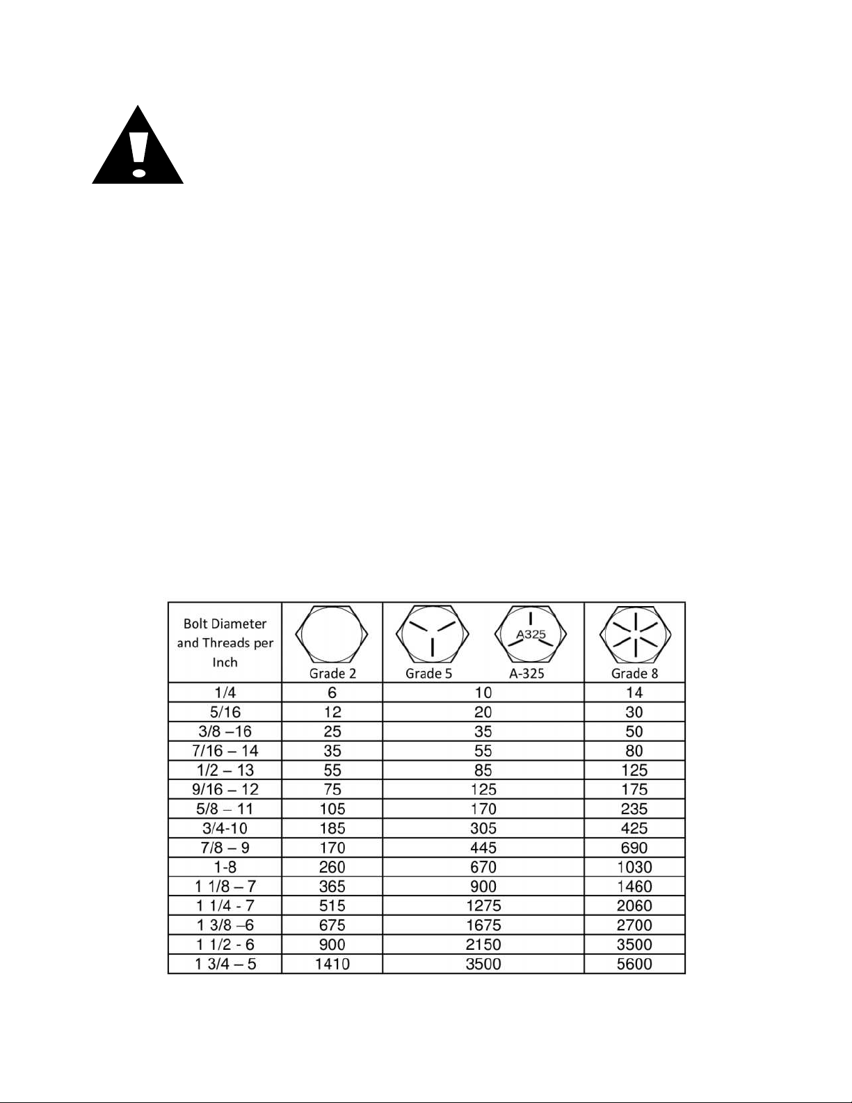
BOLT TORQUE
Important: Over-tightening hardware can cause just as much
damage as under-tightening. Tightening hardware beyond the
recommended range can reduce its shock load capacity.
All hardware on the TitanTM Residue Manager is Grade 5 or Grade 8,
unless otherwise noted. Grade 5 cap screws are marked with three radial
lines on the head. Grade 8 cap screws are marked with six radial lines on
the head. If hardware must be replaced, be sure to replace it with hardware
of equal size, strength and thread type. Refer to the torque values chart
when tightening hardware.
The chart below is a guide for proper torque. Use it unless a specified
torque is called out elsewhere in the manual.
Torque is the force applied to the end of the handle or cheater bar, times
the length of the handle or bar.
Use a torque wrench wherever possible.
The following table shows torque in ft-lbs for coarse thread hardware.
5
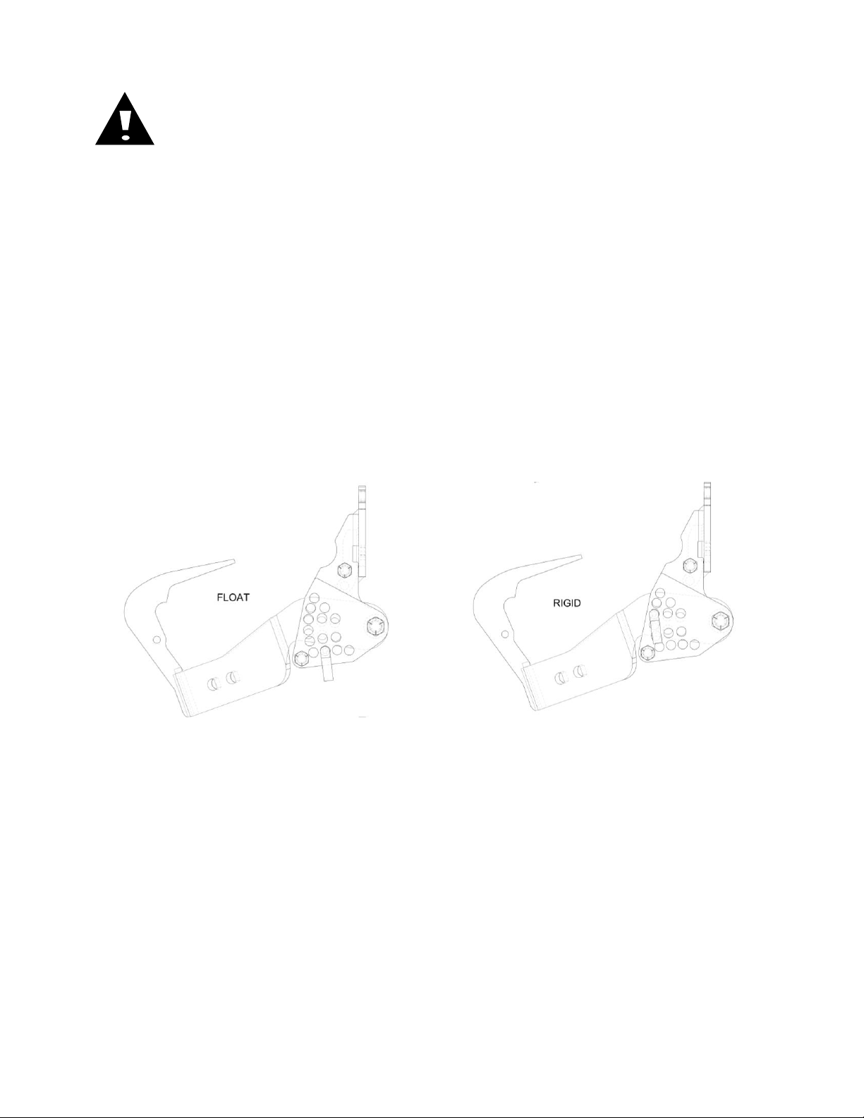
OPERATION
Where rocks are present, the residue manager should be set to
float. The system can be damaged if a rigid setting is used.
Adjust the residue manager to move crop residue aside and not to move soil.
Adjustments to the residue manager may have to be made with changing field
conditions and the type and/or amount of residue. Use the handle for leverage when
changing depth settings.
Float Settings
Install the adjustment pin below the combo arm.
To raise the wheels, lift the combo arm and move the adjustment pin up.
To lower the wheels, lift the combo arm and move the adjustment pin down.
Rigid Settings
Install the adjustment pin through the combo arm.
To raise wheels, lift the combo arm to the desired position and insert the pin.
To lower wheels, lower the combo arm to the desired position and insert the pin.
Residue Manger Do’s and Don’ts
1. DO NOT move soil; Residue Managers are designed to move crop residue
only.
2. DO NOT operate planter at slow speeds, ground speed affects how
aggressive the spoke wheels are. Operate at sufficient speed (4-6 mph) to
maintain good residue flow.
3. DO NOT expect 100% of crop residue to be cleared. It is not necessary and
would necessitate engaging the soil. The width of the cleared path depends
on ground conditions, depth setting, and ground speed.
4. DO expect to see wheels occasionally quit turning. This indicates ideal
(shallow) setting which is not moving soil.
5. DO adjust toolbar frame height 20”-22” and drawbar to level correctly. This is
very important to ensure planter opener will follow ground contours properly.
6

STOP
Read this before using the Yetter product.
IMPORTANT: failure to properly set the planter frame height and
levelness can result in less than successful operation of the planter
and the Yetter product and may result in damaged equipment. All
operators should read and thoroughly understand the instructions
given prior to using the Yetter product.
NOTE: DO NOT use this product if the planter is not adjusted properly!
Leveling the planter:
With the planter lowered to proper operating height (Usually 20”-22”).
Read the planter operator’s manual for recommended setting. Check
to be sure the toolbar and row unit parallel arms are level fore and aft. Recheck when the planter is in the field and has been fully loaded with
seed, fertilizer, granular chemicals, etc. Also, a field check with a bubble
level on the frame should be made of the hitch height to ensure level
operation front to back.
It is important for the planter to operate level laterally. Tire pressure must
be maintained at pressures specified by the manufacturer.
Field and actual planting conditions change and will dictate planter frame
heights. You must ensure that the row unit parallel arms are
approximately parallel with the ground.
IMPORTANT: For proper operation of the planter attachments and row
units, it is imperative that the planter toolbars and row unit parallel arms be
level side-to-side and front-to-rear. The toolbar frame should operate at a
20”-22” height from the planting surface. Check the manufacturer’s
operator’s manual for instructions on how to adjust the frame height and
levelness.
7
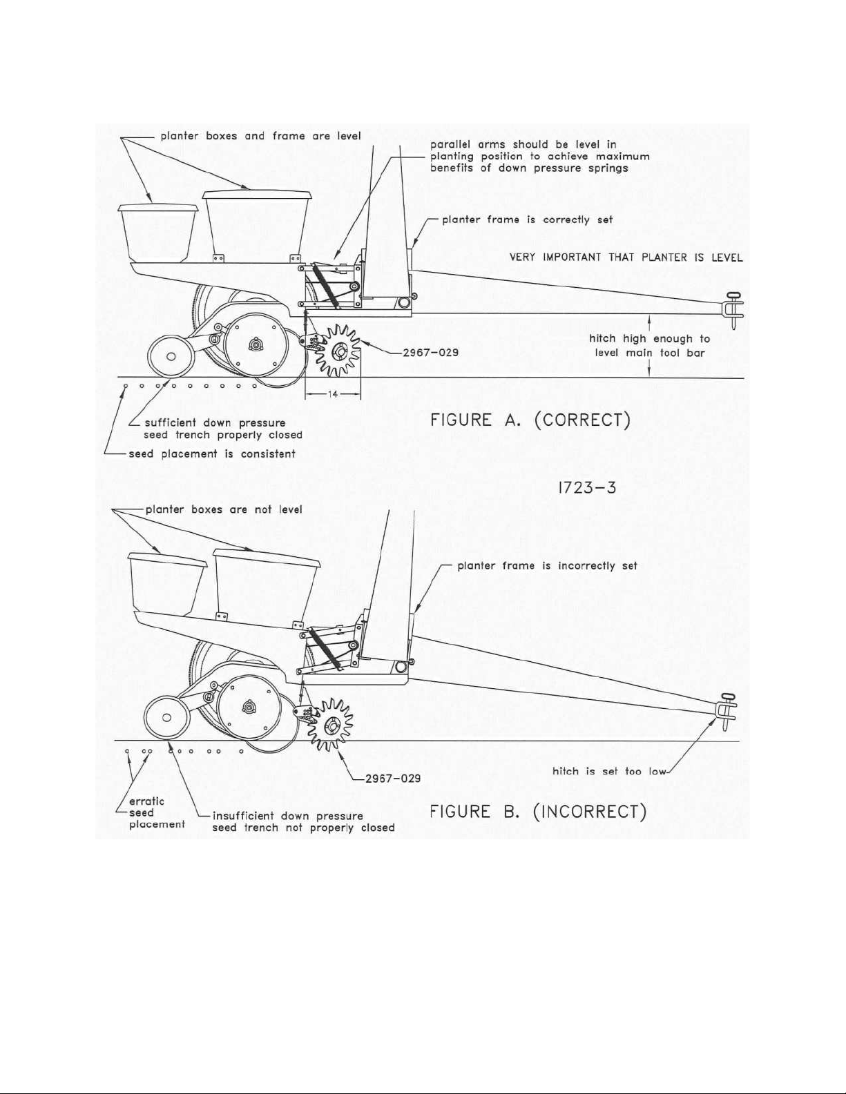
PLANTER ADJUSTMENT
8
 Loading...