

Page 1

2967-030
“TITAN”
FLOATING RESIDUE MANAGER
YETTER MANUFACTURING CO.
FOUNDED 1930
Colchester, IL 62326-0358
Toll free: 800/447-5777
309/776-3222 (Fax)
Website: www.yetterco.com
E-mail: info@yetterco.com
UNIVERSAL
UNIT MOUNTED
Page 2

FOREWORD
You’ve just joined an exclusive but rapidly
growing club.
For our part, we want to welcome you to the
group and thank you for buying a Yetter Product.
We hope your new Yetter implement will help
you achieve both increased productivity and
increased efficiency so that you may generate
more profit. This operator’s manual has been
designed into six major sections.
Foreword, Safety Precautions, assembly
instructions, Operation, parts identification and
troubleshooting.
It is important the owner/operator knows the
implement model number. Write the model
number in the space provided and use it in all
correspondence when referring to the
implement.
Throughout the manual references may be
made to left side and right side. These terms
are used as viewed from the operator’s seat
facing the front of the tractor.
This SAFETY ALERT SYMBOL
indicates important safety messages in
the manual. When you see this symbol, be alert
to the possibility of PERSONAL INJURY and
carefully read the message that follows.
The word NOTE is used to convey information
that is out of context with the manual text. It
contains special information such as
specifications, techniques, reference information
WARRANTY POLICY
Yetter Manufacturing warrants all products manufactured and sold by it against defects in material.
This warranty being expressly limited to replacement at the factory of such parts or products as will
appear to be defective after inspection. This warranty does not obligate the Company to bear cost of
labor in replacement of parts. It is the policy of the company to make improvements without incurring
obligations to add them to any unit already sold. No warranty is made or authorized to be made, other
than herein set forth. This warranty is in effect for one year after purchase.
Model Number:_________________________
Dealer :___________________
Yetter Manufacturing warrants its own products only and cannot be responsible for damage to
equipment on which it is mounted.
and other information of a supplementary nature.
The word IMPORTANT is used in the text when
immediate damage will occur to the machine
due to improper technique or operation.
Important will apply to the same information as
specified by note only of an immediate and
urgent nature.
It is the responsibility of the user to read the
operator’s manual and comply with the safe and
correct operating procedure and to lubricate and
maintain the product according to the
maintenance schedule in the operator’s manual.
The user is responsible for inspecting his
machine and for having parts repaired or
replaced when continued use of the product
would cause damage or excessive wear to the
other parts.
It is the user’s responsibility to deliver his
machine to the Yetter dealer who sold him the
product for service or replacement of defective
parts that are covered by the warranty policy.
If you are unable to understand or follow
the instructions provided in the publication,
consult you local Yetter dealer or contact:
YETTER MANUFACTURING CO.
309/776-4111
800/447-5777
309/776-3222 (FAX)
Website: www.yetterco.com
E-mail: info@yetterco.com
2
Page 3
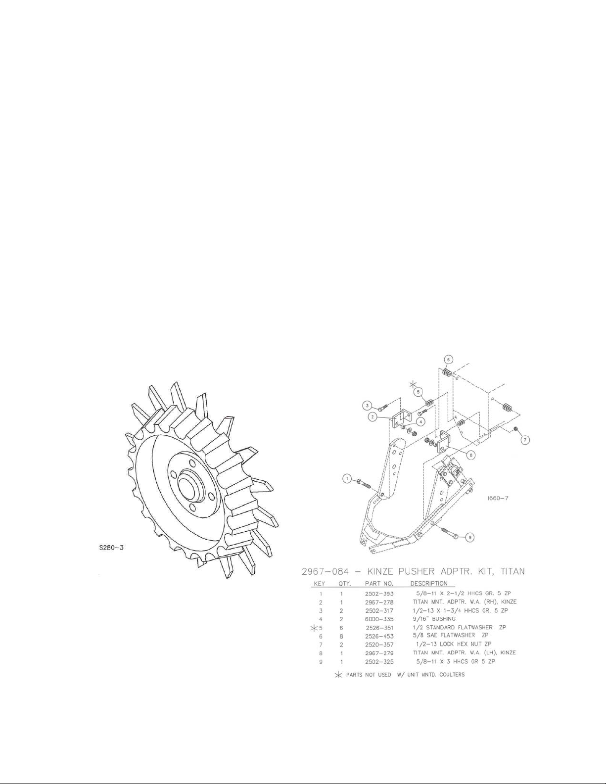
TABLE OF CONTENTS
Introduction………………………………………………………………..2
Warranty……………………………….……………………………….….2
Table of Contents………………………………………………………...3
Optional Equipment………………………………………………………3
Safety Information………………………………………………….……..4
Application/Use Guide……………………………………………………5
Assembly Instruction…………………….……………………………..6-8
Operation……………………………...…………………………….…….9
Maintenance………………………..……………………………….…….9
Parts Identification………………………………..………….…….……10
Trouble Shooting………………….…………………………..…………11
OPTIONAL EQUIPMENT
2967-555 FLOATER WHEEL
L.H. ASSEMBLY SHOWN
(2) REQUIRED PER ROW
3
Page 4

SAFETY
A brief description of signal words that may be used in this manual:
CAUTION: Used as a general reminder of good safety practices or to direct attention to unsafe
practices.
WARNING: Denotes a specific potential hazard.
DANGER: Denotes the most serious specific potential hazard.
SAFETY PRECAUTIONS
You can make your farm a safer place to live and work if you observe the safety precautions given.
Study these precautions carefully and insist that those working with you and for you follow them.
Finally, remember this: an accident is usually caused by someone’s carelessness, neglect or
oversight.
WARNING
Never clean, lubricate or adjust a machine that is in motion. Always lower or block the implement
before performing service.
If the machine must be serviced in the raised position, jack or block it up to prevent it from accidentally
falling and injuring someone.
Do not allow riders on the tractor or implement.
Use speeds and caution dictated by the terrain being traversed. Do not operate on any slope steep
enough to cause tipping or loss of control.
Be sure all personnel are clear of the immediate area before operating.
Read and understand the operator’s manual and require all other persons who will operate the
equipment to do the same.
Be familiar with all tractor and implement controls and be prepared to stop engine and implements
quickly in an emergency.
CAUTION
Consult your implement and tractor operator’s manual for correct and safe operating practices.
Beware of towed implement width and allow safe clearance.
FAILURE TO HEED MAY RESULT IN PERSONAL INJURY OR DEATH.
4
Page 5

TITAN RESIDUE MANAGER
APPLICATION / USE GUIDE
IMPORTANT: On some planters the row unit is closer to lift wheels, frames and chain idlers on
one side of the row unit than the other side. Both sides of all row units need to be checked for
sufficient clearance. The Titan Residue Manager can be assembled as a R.H. or a L.H. unit as
needed for clearance. Measurements are taken at the bolt heads of the rear parallel linkage bolts.
NOTE: Measure for clearance when planter row units are in the planting position.
5
Page 6

IMPORTANT: Fertilizer extension bar kit, set backs or longer parallel arms may have to be used
on some planters to have enough clearance between the residue manager wheels, fertilizer openers,
planter transport frames and drive shafts. Please check to see if your planter “measures up” to handle
a Titan Residue Manager.
ASSEMBLY INSTRUCTIONS
STEP 1. Attach a 2967-558 mount plate and the 2967-561 adapter plate (JD MEII/MEII PLUS
ONLY) using 2) 5/8” x 3” bolts, 1) 5/8” flat washer and 2) 5/8” lock nuts to the R.H. side of the planter
row units. Install the top bolt before removing the bottom bolt. Fully tighten the fasteners.
NOTE: On some planters the 2967-561 adapter plate and the 5/8” flat washer are not used.
STEP 2. Assemble the quick adjust. Attach the 2) 2984-319 spacer bushings to the 2967-559 slide bar
using 2) ½” x 1 ¾” bolts and lock nuts. Attach the 2967-560 quick adjust plate and 2967-562 handle to the
2967-559 slide bar using the ½” x 3” flat head bolt, 2550-769 spring, 6000-335 bushing and lock nut. Do
not over tighten, the handle should be able to move on the 2967-560 adjustment plate when handle is
pulled on and the spring compressed. Remove the rear upper L.H. bolt of the planter parallel linkage and
attach the quick adjust assembly, 5/8” x 1” O.D. washer, 2967-557 spacer, 2967-558 mount plate, 2967561 adapter plate and 5/8” flat washer using 1) 5/8” x 4” bolt and 5/8” lock nut. Remove the rear, lower
L.H. bolt and attach the 2967-558 mount plate and 2967-561 adapter plate using 1) 5/8” x 3” bolt and 5/8”
lock nut. Insert a 5/8” x 2” bolt through the 2967-558 mount plate, 2967-557 spacer, 5/8” x 1 O.D. washer,
quick adjust assembly and locknut. Fully tighten all fasteners at this point.
6
Page 7

ASSEMBLY INSTRUCTIONS
STEP 3 Attach the 2967-273 combo arm to the R.H. 2967-558 mount plate using 1) 5/8” x
1 ¾” bolt, bushing, 5/8” flat washer and lock nut. Insert the 5/8” bolt through the middle hole
of the combo arm.
STEP 4 Attach the 2967-273 combo arm and 29697-556 combo handle to the L.H. 2967-
558 mount plate using 1) 5/8” x 2 ½” bolt, bushing, 5/8” flat washer and 5/8” lock nut. Attach
the 2967-556 combo handle to the 2967-273 combo arm using 1) 5/8” x 1 ¾” bolt and lock
nut. Fully tighten all fasteners.
7
Page 8

ASSEMBLY INSTRUCTIONS
STEP 5. Assemble the residue manager wheel to the hub and bearing.
NOTE: R.H. and L.H. wheel assemblies are needed.
IMPORTANT: 2527-530 washers must be installed or Residue Manager Wheel and hub assembly
will fall off during use.
NOTE: Remove the seal from the exposed side of the bearing if you choose to grease the
bearing, otherwise the bearing is sealed.
8
Page 9

NOTE: During assembly be sure to align the grease-fitting hole in all the components to assure
proper lubrication of the bearing. Use a general-purpose grease before use of the Residue
Managers.
STEP 6. Fasten the R.M. wheel assemblies to the 2967-273 combo arm using 5/8” lock
washers and 5/8” hex nuts. Adjust the bearing shield to top dead center, rotated forward.
OPERATION
CAUTION: Where rocks are present the residue manager should be set in the
“float” position, not locked down.
STEP 1. Adjust the residue manager to move crop residue aside and not move any soil.
Adjustments to the residue manager may have to be made when changing field conditions
and type and amount of residue. Use a ½” drive socket wrench for leverage when changing
depth settings. To adjust the R.M. wheels deeper, raise the quick adjust handle and to
adjust the R.M. wheels shallower – lower the quick adjust handle. By removing the lowest
bolt on the 2967-559 slide bar the residue manager wheels can be allowed to “float” and the
quick adjust will act as a down stop. If residue managers are set to “float”, check for
clearance with drive shafts and frames.
ROW CLEANER DO’S AND DON’TS
1. DO NOT move soil; Residue Managers are designed to move crop
residue only.
2. DO NOT operate planter at slow speeds, ground speed affects how
aggressive the spoke wheels are; operate at sufficient speed (4-6 mph)
to maintain good residue flow.
3. DO NOT expect 100% of crop residue to be cleared, it is not necessary
and would necessitate engaging the soil. The width of path cleared
depends on ground conditions, depth setting and ground speed.
4. DO expect to see wheels occasionally quit turning, indicates ideal
(shallow) setting which is not moving soil.
5. DO adjust toolbar frame height 20”-22” and drawbar correctly. Very
important to ensure planter opener will follow ground contours
properly.
9
Page 10

MAINTENANCE
STEP 1. Regularly inspect the residue manager for loose or worn bolts. Repair and replace
as needed.
STEP 2. If you choose to leave the seal, then you need to fill cavity with grease. If you
choose to remove the seal, then you need to fill cavity and maintain the grease every 50
hours of use.
10
IMPORTANT: For proper operation, the planter frame must operate level (for, aft
and side to side) and at the correct height, typically 20”-22”.
PARTS IDENTIFICATION
Page 11

TROUBLESHOOTING
Figure A. (Correct)
Figure B. (Incorrect)
Figure A. – The planter frame is 20” off the ground. To ensure this, visually check to see that the
planter boxes are level and that the planter unit parallel arms are also parallel with the ground. When
using planter attachments located in front of the planter unit, this setting is very important.
Figure B. – The planter hitch is set too low while the planter remains at 20” off the ground. Notice
from the illustration that the unit mounted coulter is running deeper in the ground.
Note – Both illustrations are strictly for reference only. They are intended to show that proper
adjustment of the hitch height is crucial. Consult your planter operator’s manual for the proper height
adjustment of the hitch.
Note – The drawbar extension kit (6600-128) offered by Yetter Mfg. Co. may be used to alleviate the
condition shown in figure B.
11
Page 12

Our name
Is getting known
Just a few years ago, Yetter products were sold primarily to the
Midwest only. Then we embarked on a program of expansion and
moved into the East, the South, the West and now north into
Canada. We’re even getting orders from as far away as Australia
and Africa.
So, when you buy Yetter products . . .you’re buying a name that’s
recognized. A name that’s known and respected. A name that’s
become a part of American agriculture and has become
synonymous with quality and satisfaction in the field of conservation
tillage.
Thank you.
YETTER MANUFACTURING CO.
Colchester, IL 62326-0358 309/776-4111
Toll Free 800/447-5777
Fax 309/776-3222
Website: www.yetterco.com
E-mail: info@yetterco.com
2565-681 01/08 Great River Printing, Hamilton, IL
12
 Loading...