


2960-130
UNIT MOUNTED DOUBLE
ARM CONSERVATION
YETTER MANUFACTURING CO.
FOUNDED 1930
Colchester, IL 62326-0358
Toll free: 800/447-5777
309/776-3222 (Fax)
Website: www.yetterco.com
E-mail: info@yetterco.com
COULTER

FOREWORD
You’ve just joined an exclusive but rapidly
growing club.
For our part, we want to welcome you to the
group and thank you for buying a Yetter Product.
We hope your new Yetter products will help you
achieve both increased productivity and
increased efficiency so that you may generate
more profit. This operator’s manual has been
designed into six major sections.
Foreword, Safety Precautions, assembly
instructions, Operation, parts identification and
troubleshooting.
Throughout the manual references may be
made to left side and right side. These terms
are used as viewed from the operator’s seat
facing the front of the tractor.
This SAFETY ALERT SYMBOL indicates
important safety messages in the
manual. When you see this symbol, be
alert to the possibility of PERSONAL INJURY
and carefully read the message that follows.
The word NOTE is used to convey information
that is out of context with the manual text. It
contains special information such as
specifications, techniques, reference information
and other information of a supplementary
nature.
The word IMPORTANT is used in the text when
immediate damage will occur to the machine
due to improper technique or operation.
Important will apply to the same information as
specified by note only of an immediate and
urgent nature.
It is the responsibility of the user to read the
operator’s manual and comply with the safe and
correct operating procedure and to lubricate and
maintain the product according to the
maintenance schedule in the operator’s manual.
The user is responsible for inspecting his
machine and for having parts repaired
or replaced when continued use of the
product would cause damage or excessive wear
to the other parts.
It is the user’s responsibility to deliver his
machine to the Yetter dealer who sold him the
product for service or replacement of defective
parts that are covered by the warranty policy.
If you are unable to understand or follow the
instructions provided in the publication, consult
you local Yetter dealer or contact:
YETTER MANUFACTURING CO.
309/776-4111
800/447-5777
309/776-3222 (FAX)
Website: www.yetterco.com
E-mail: info@yetterco.com
WARRANTY POLICY
Yetter Manufacturing warrants all products manufactured and sold by it against defects in material. This
warranty being expressly limited to replacement at the factory of such parts or products as will appear to
be defective after inspection. This warranty does not obligate the Company to bear cost of labor in
replacement of parts. It is the policy of the company to make improvements without incurring obligations
to add them to any unit already sold. No warranty is made or authorized to be made, other than herein
set forth. This warranty is in effect for one year after purchase.
Yetter Manufacturing warrants its own products only and cannot be responsible for
damage to equipment on which mounted.
2

SAFETY
A brief description of signal words that may be used in this manual.
CAUTION: Used as a general reminder of good safety practices or to direct attention to unsafe practices.
WARNING: Denotes a specific potential hazard.
DANGER: Denotes the most serious specific potential hazard.
SAFETY PRECAUTIONS
You can make your farm a safer place to live and work if you observe the safety precautions given. Study
these precautions carefully and insist that they be followed by those working with you and for you.
Finally, remember this: an accident is usually caused by someone’s carelessness, neglect or oversight.
WARNING
Never clean, lubricate or adjust a machine that is in motion. Always install the transport lock pins and
bracket when transporting for any length of time or on public roadways.
If required to service unit in raised position, be sure to install all transport lock pins and locking bracket.
Be sure the implement is securely locked in the 3-point quick hitch before operating.
Do not allow children to operate this equipment.
Do not allow riders on the tractor or implement.
Use speeds and caution dictated by the terrain being traversed. Do not operate on any slope steep enough
to cause tipping or loss of control.
Be sure all personnel are clear of the immediate area before operating.
Read and understand the operator’s manual and require all other persons who will operate the equipment
to do the same.
In operating on public roadways, where legal, be certain all lighting is operating properly and observe all
traffic laws. Ensure slow moving vehicle emblem on tractor is visible.
Maximum towing speed is 20 mph when conditions permit.
Beware of increased stopping distances and control effort when operating with implements attached.
Be familiar with all tractor and implement controls and be prepared to stop engine and implements quickly in
an emergency.
CAUTION
Consult your implement and tractor’s operator’s manual for correct and safe operating practices.
Beware of towed implement width and allow safe clearance.
FAILURE TO HEED MAY RESULT IN PERSONAL INJURY OR DEATH.
3
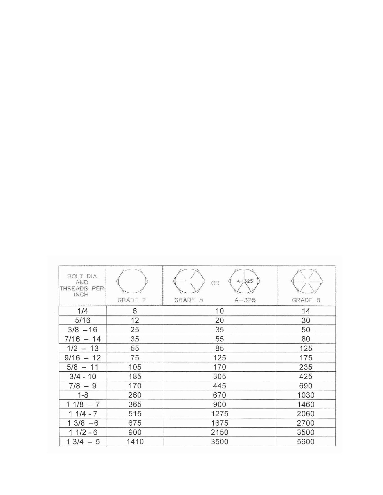
TABLE OF CONTENTS
Cover Page………………………………………………………………….. 1
Foreword…………………………………………………………………….. 2
Safety Symbols
and Meanings …
……………………………………………………2-3
Table of Contents…………………………………………………………… 4
Torque Specifications.……………………………………………………… 4
Assembly Instructions.…………………………………………………….5-6
Operation……………………………………….…………………………..7-8
Maintenance…………………………………………………………………..8
Parts Identification………………………...…………………………….……9
Trouble Shooting…………………………………………………………10-11
BOLT TORQUE
READ THESE INSTRUCTIONS FIRST:
1. Improperly tightened bolts will result in damage, breakage, expense, and down time.
2. Always replace bolts with the specified grade and type.
3. Torque properly before first use of the machine and every 2-4 hours of use until you are sure bolts are staying
tight.
4. The chart below is a guide for proper torque. Use it unless a specified torque is called out elsewhere in the
manual.
5. Toque is the force you apply to the wrench handle or the cheater bar, times the length of the handle or bar.
6. Use a torque wrench whenever possible.
The following table shows torque in foot pounds.
4
INTRODUCTION
The 2960-130 Unit Mounted Double Arm Conservation Coulter has been designed as a ‘universal’ fitment
for several makes of planter units.
By using two different arrangements of the same parts, the coulter assembly will fit several makes and
models of planters. One arrangement of the faceplate mount brackets will fit the John Deere MaxEmerge 2,
Plus, and Pro type planters. Another arrangement of the faceplate mount brackets will fit the 7000 John
Deere units, Kinze, White 6000 and 8000 units, and the Yetter planter row units. Several styles of blades
are available for every tillage practice, every soil type, and every residue condition, so you can choose the
one that’s right for you.
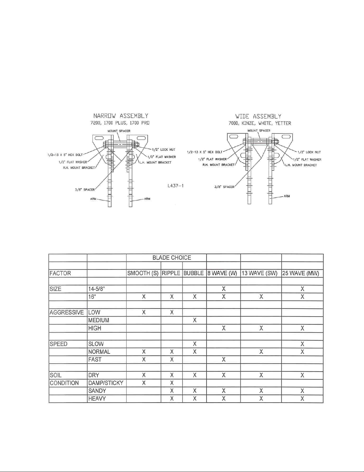
NOTE: The coulter is factory assembled as a wide assembly. If you are mounting the coulter to a planter
that uses a narrow assembly, rearrange the mounting brackets and spacers at this time.
5
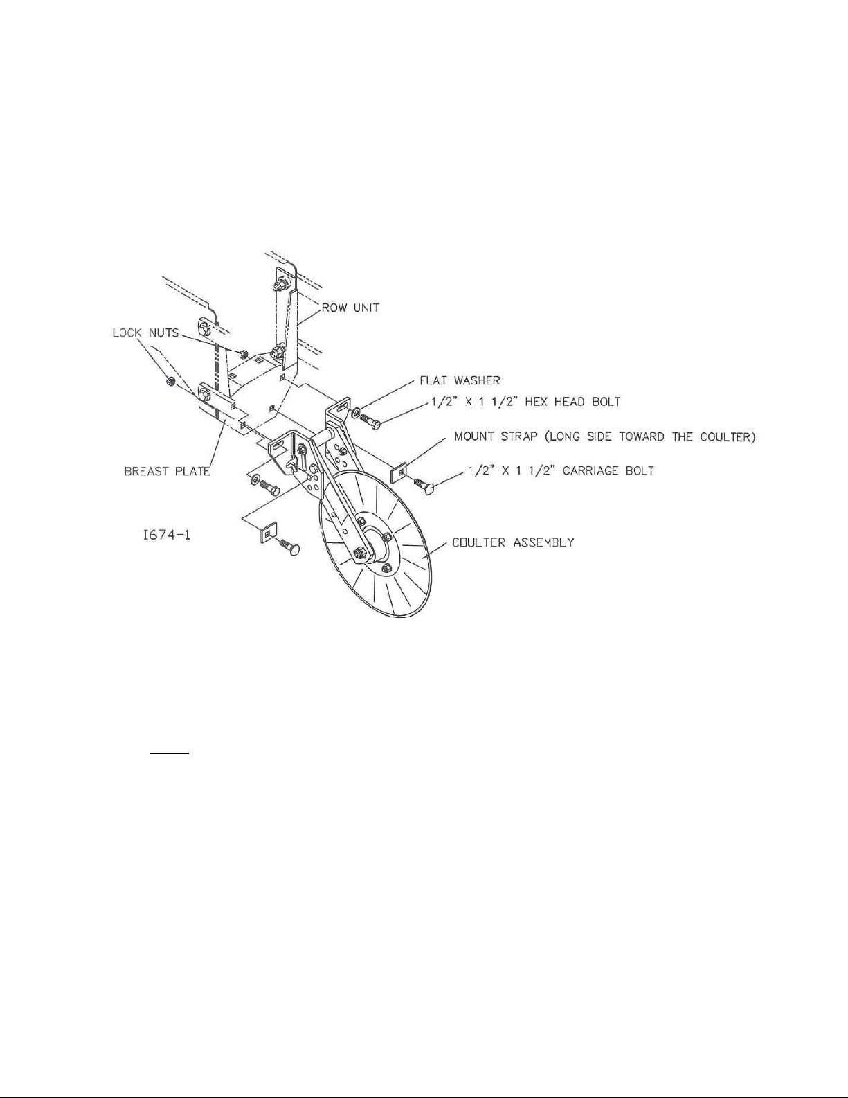
COULTER INSTALLATION
1. Attach the double arm coulter assembly to the planter row units at the upper
breastplate mounting holes using 2) ½” x 1 ½” bolts, flat washers and lock nuts.
2. Insert the 2) ½” x 1 ½” carriage bolts through the mount straps (long side toward
center of row) breast plate mounting holes and secure with lock nut.
3. Align the coulter blade with the planter opener blades by sliding the coulter
assembly on the planter breastplate, and then tighten the fasteners (torque to 85 ft.
lbs.) securing the coulter assembly to the planter unit.
4. After
coulter assembly is tightened to planter unit, the upper coulter depth
adjustment bolt can be tightened (torque 85 ft/lbs.). By tightening this bolt last, the
coulter will be allowed to move freely when making future depth adjustments.
6
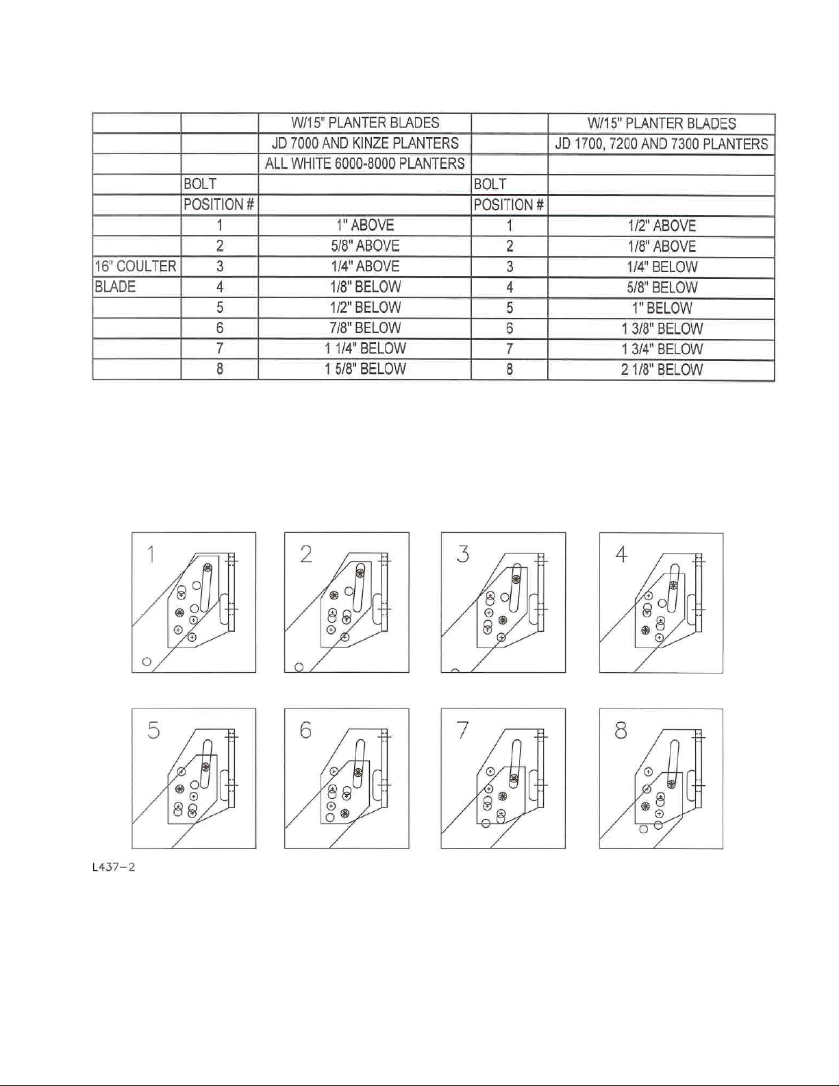
OPERATION
Note: This is a reference guide table – all measurements were taken with the row unit
and planter frame level/parallel to the soil.
COULTER BLADE DEPTH ADJUSTMENT
BOLT LOCATION
Adjustment:
Adjust coulter blade depth equal to or above the planter opener blades. Adjust the blade
depth as required for blade wear. Planter blades that are worn to 14 ¼” or smaller in diameter
should be replaced. Example: 14 ¼” blades will have a 3/8” shallower planting depth than 15”
blades at the same gauge wheel adjustment setting. For replacement parts a 14 5/8” wavy
blade is available in your choice of 8 wave (2571-164) or 25 wave (2571-166).
7
OPERATION
1. Set/mount coulter blades to run perpendicular to the soil. Operation depth and blade
wear can be affected if the coulter is mounted crooked or if the toolbar is not level side to
side.
2. After a few hours of use, check all bolts for tightness and proper torque.
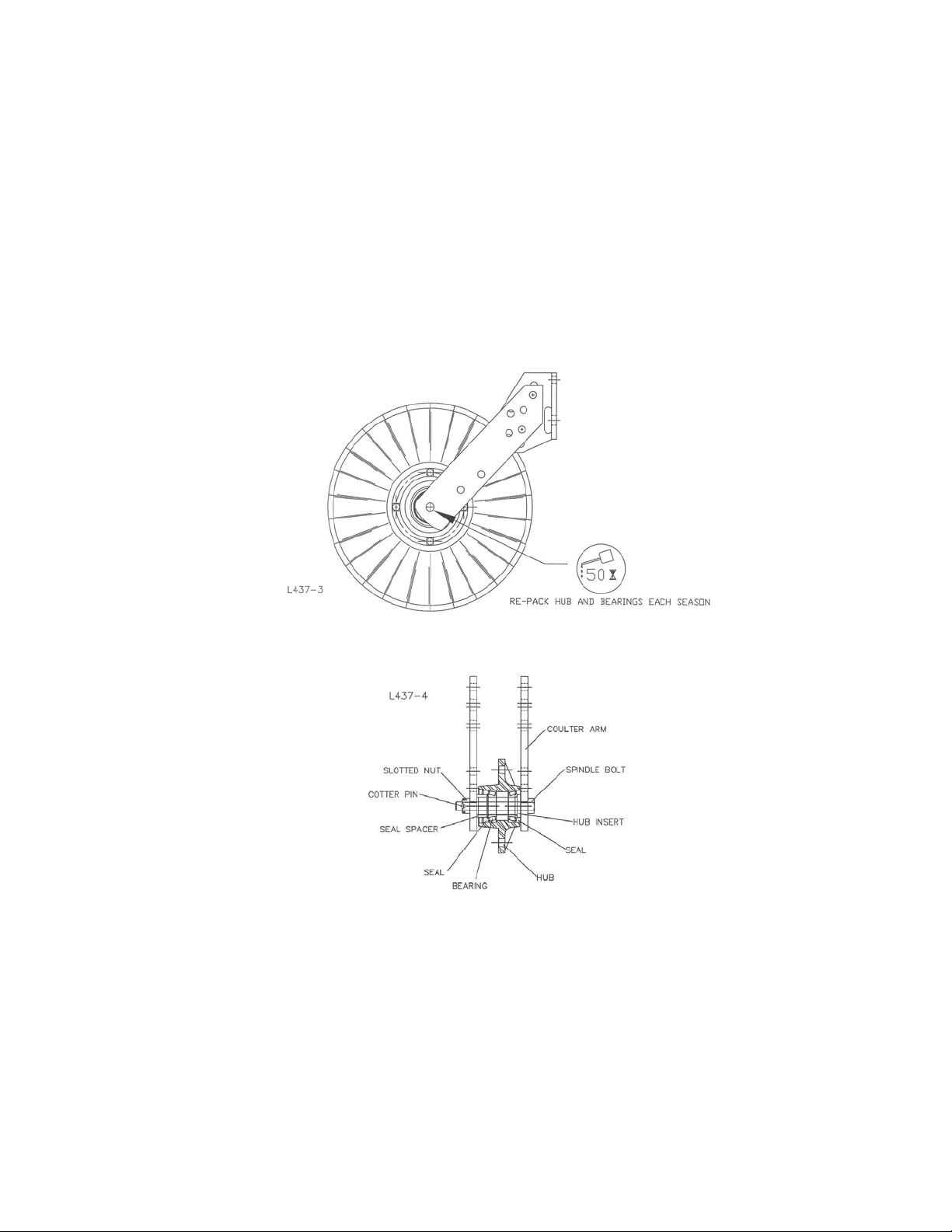
3. After a day of use (10-12 hours) check coulter hubs for loose bearings. There should be
no endplay in the hub bearings allowing the blade to wobble. If necessary, remove cotter
pin and adjust the slotted nut to remove wobble, recommended torque of 15 ft. lbs. and
re-insert cotter pin. If the wobble or looseness cannot be corrected, the bearings, cups
and seals will need to be replaced.
DO NOT USE WORN OR DAMAGED PARTS.
MAINTENANCE
LUBRICATION: USE #2 MULTI-PURPOSE LITHIUM GREASE
To ensure longevity and reliability of the 2960-130 coulter, the recommended lubrication
schedule should be followed using multi-purpose grease at hourly intervals as indicated.
BEARING ADJUSTMENT:
1. Raise the toolbar until the blade is clear of the ground. Place a safety stand under the toolbar.
Remove the cotter pin, slotted nut, washer and bolt from the hub assembly. Remove the blade
from the hub assembly.
2. Remove bearing cones and seals from hub.
3. Wash the old grease from the hub, bearing cups, spindle spacers, seals and bearing cones.
Inspect the condition of the bearing cups, cones and seals. Replace if necessary.
4. Apply #2 multi-purpose lithium grease on each bearing. Make sure the space around each roller is
filled. Lubricate the bearing cups.
5. Position the bearing in the cup and install the seal. Lubricate the seal lips and proceed with re-
assembly of the removed parts including the blade. Blade bolt torque is 90 to 96 ft. lbs.
6. Tighten the slotted nut to 15 ft. lbs. or until a definite drag is felt when the blade is turned by hand.
Tighten the nut one slot position to line up the cotter pin hole with a slot. Secure the nut with a new
cotter pin.
8

PARTS IDENTIFICATION
9

Problem
Cannot adjust coulter
depth shallow enough.
Cannot adjust coulter deep
enough.
Coulter will not penetrate.
Coulter penetrates too
much.
Seed placement is too
deep.
Optional wavy blade
disturbs too much soil.
Drive chain rubs on
springs.
No spring tension.
10
TROUBLESHOOTING
Cause
Planter frame not set
correctly.
Coulter blade is too big.
Planter opener blades
worn.
Coulter blade worn too
small.
Lack of spring tension.
Excessive spring down
pressure.
Coulter blade set too deep
relative to openers.
Soil too damp or loose.
Close fitting parts.
Planter frame not set
correctly.
Spring adjustment pin not
installed properly.
Broken springs.
Solution
Ensure that in operation
the planter frame is at
correct height (20”-22”)
and level the toolbar,
refer to opposite page.
Blade must be 16”
diameter or smaller.
Replace planter opener
blades if worn smaller than
14 ¼” diameter.
Replace coulter blade.
Increase spring tension.
Reduce spring tension.
Shallow up coulter depth.
Reduce ground speed.
Install a less aggressive
blade. Example: smooth or
ripple.
Not detrimental to
operation of planter.
Check planter frame
settings, see above.
Check installation of pin.
Replace broken or
damaged parts.
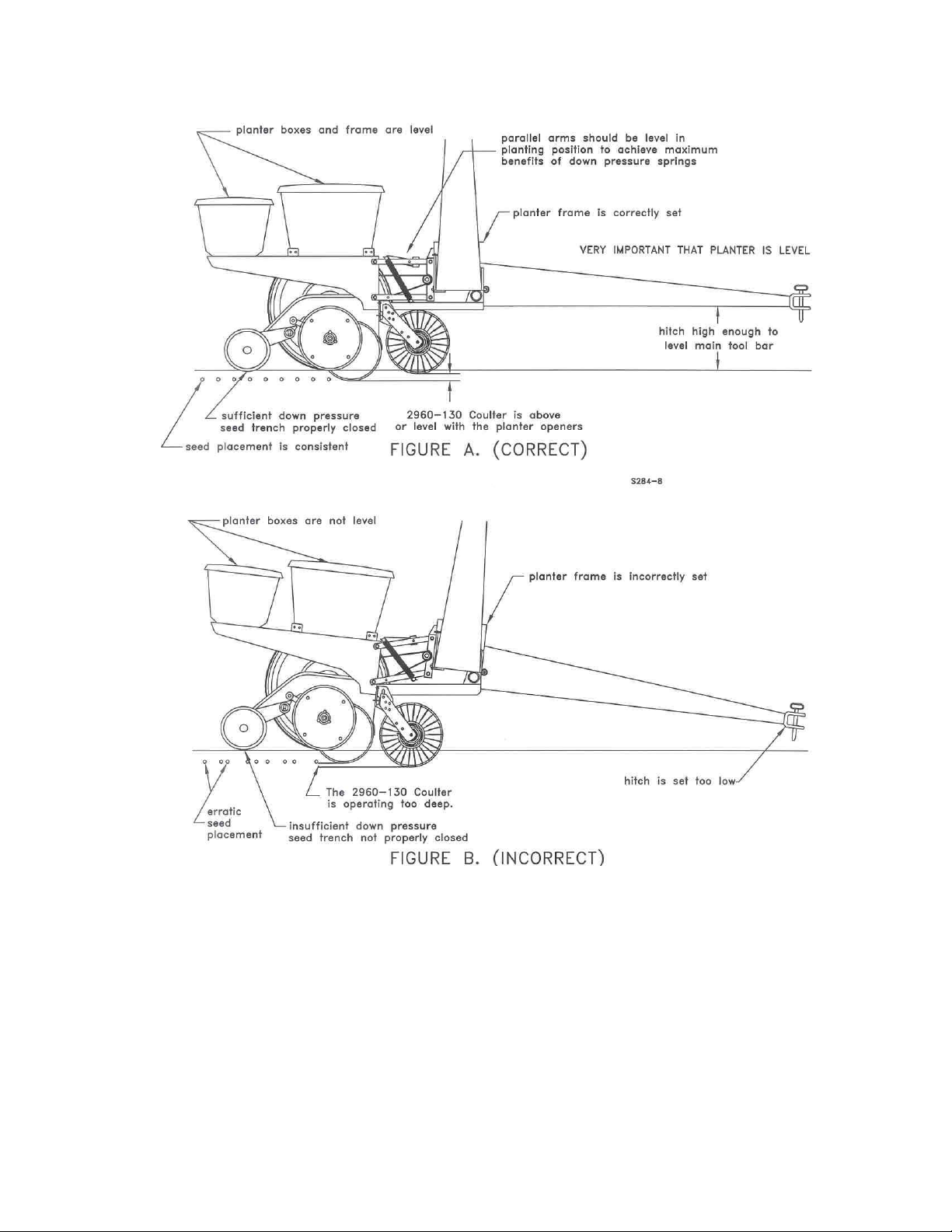
PLANTER HEIGHT ADJUSTMENT
Figure A. – The planter hitch and frame are both 20” off the ground. To ensure this, visually
check to see that the planter boxes are level and that the planter unit parallel arms are also
parallel with the ground. When using planter attachments located in front of the planter unit,
this setting is very important.
Figure B. – The planter hitch is set too low while the planter frame remains at 20” off the ground!
Notice from the illustration that the unit mounted coulter is running deeper in the ground than the
planter unit. This condition can result in the formation of an air pocket below the seed bed which
will in turn dramatically decrease seed growth.
NOTE: Both illustrations are strictly for reference only. They are intended to show that
proper adjustment of the hitch height is critical. Consult your planter operator’s manual for the
proper height adjustment of the hitch.
11

Our name
Is getting known
Just a few years ago, Yetter products were sold primarily to the
Midwest only. Then we embarked on a program of expansion and
moved into the East, the South, the West and now north into Canada.
We’re even getting orders from as far away as Australia and Africa.
So, when you buy Yetter products . . .you’re buying a name that’s
recognized. A name that’s known and respected. A name that’s
become a part of American agriculture and has become synonymous
with quality and satisfaction in the field of conservation tillage.
Thank you.
YETTER MANUFACTURING CO.
Colchester, IL 62326-0358 309/776-4111
Toll Free 800/447-5777
Fax 309/776-3222
Website: www.yetterco.com
E-mail: info@yetterco.com
2565-484_REV_A 03/09
12
 Loading...