


2960 SERIES II
UNIT MOUNTED
CONSERVATION
YETTER MANUFACTURING CO.
FOUNDED 1930
Colchester, IL 62326-0358
Toll free: 800/447-5777
309/776-3222 (Fax)
Website: www.yetterco.com
E-mail: info@yetterco.com
COULTER

FOREWORD
You’ve just joined an exclusive but rapidly
growing club.
For our part, we want to welcome you to the
group and thank you for buying a Yetter Product.
We hope your new Yetter products will help you
achieve both increased productivity and
increased efficiency so that you may generate
more profit. This operator’s manual has been
designed into six major sections.
Foreword, Safety Precautions, assembly
instructions, Operation, parts identification and
troubleshooting.
Throughout the manual references may be
made to left side and right side. These terms
are used as viewed from the operator’s seat
facing the front of the tractor.
This SAFETY ALERT SYMBOL indicates
important safety messages in the manual.
When you see this symbol, be alert to
the possibility of PERSONAL INJURY and
carefully read the message that follows.
The word NOTE is used to convey information
that is out of context with the manual text. It
contains special information such as
specifications, techniques, reference information
and other information of a supplementary
nature.
The word IMPORTANT is used in the text when
immediate damage will occur to the machine
due to improper technique or operation.
Important will apply to the same information as
specified by note only of an immediate and
urgent nature.
It is the responsibility of the user to read the
operator’s manual and comply with the safe and
correct operating procedure and to lubricate and
maintain the product according to the
maintenance schedule in the operator’s manual.
The user is responsible for inspecting his
machine and for having parts repaired or
replaced when continued use of the product
would cause damage or excessive wear to the
other parts.
It is the user’s responsibility to deliver his
machine to the Yetter dealer who sold him the
product for service or replacement of defective
parts that are covered by the warranty policy.
If you are unable to understand or follow the
instructions provided in the publication, consult
you local Yetter dealer or contact:
YETTER MANUFACTURING CO.
309/776-4111
800/447-5777
309/776-3222 (FAX)
Website: www.yetterco.com
E-mail: info@yetterco.com
WARRANTY POLICY
Yetter Manufacturing warrants all products manufactured and sold by it against defects in material. This warranty
being expressly limited to replacement at the factory of such parts or products as will appear to be defective after
inspection. This warranty does not obligate the Company to bear cost of labor in replacement of parts. It is the policy
of the company to make improvements without incurring obligations to add them to any unit already sold. No
warranty is made or authorized to be made, other than herein set forth. This warranty is in effect for one year after
purchase.
Model Number:_________________________
Dealer :_______________________________
Yetter Manufacturing warrants its own products only and cannot be responsible for damage to equipment on
which mounted.
2

SAFETY
A brief description of signal words that may be used in this manual.
CAUTION: Used as a general reminder of good safety practices or to direct attention to unsafe practices.
WARNING: Denotes a specific potential hazard.
DANGER: Denotes the most serious specific potential hazard.
SAFETY PRECAUTIONS
You can make your farm a safer place to live and work if you observe the safety precautions given. Study
these precautions carefully and insist that they be followed by those working with you and for you.
Finally, remember this: an accident is usually caused by someone’s carelessness, neglect or oversight.
WARNING
Never clean, lubricate or adjust a machine that is in motion. Always install the transport lock pins and bracket when
transporting for any length of time or on public roadways.
If required to service unit in raised position, be sure to install all transport lock pins and locking bracket.
Do not allow children to operate this equipment.
Do not allow riders on the tractor or implement.
Use speeds and caution dictated by the terrain being traversed. Do not operate on any slope steep enough to cause
tipping or loss of control.
Be sure all personnel are clear of the immediate area before operating.
Read and understand the operator’s manual and require all other persons who will operate the equipment to do the
same.
In operating on public roadways, where legal, be certain all lighting is operating properly and observe all traffic laws.
Ensure slow moving vehicle emblem on tractor is visible.
Beware of increased stopping distances and control effort when operating with implements attached.
Be familiar with all tractor and implement controls and be prepared to stop engine and implements quickly in an
emergency.
CAUTION
Consult your implement and tractor’s operator’s manual for correct and safe operating practices.
FAILURE TO HEED MAY RESULT IN PERSONAL INJURY OR DEATH.
3

OPERATION PRECAUTIONS
STOP
Read this before using the Yetter product.
- MACHINE OPERATION
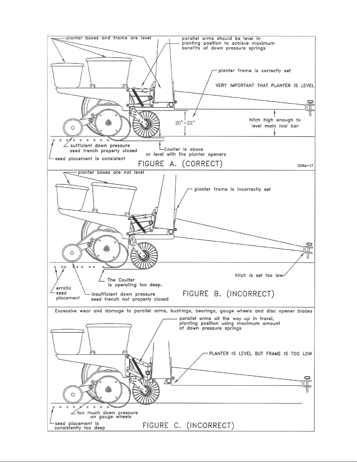
IMPORTANT: failure to properly set the planter frame height and
levelness can result in less than successful operation of the planter
and the Yetter product and may result in damaged equipment. All
operators should read and thoroughly understand the instructions
given prior to using the Yetter product.
NOTE: DO NOT use this product if the planter is not adjusted properly!
Leveling the planter:
With the planter lowered to proper operating height (Usually 20”-22”).
Read the planter operator’s manual for recommended setting. Check to
be sure the toolbar and row unit parallel arms are level fore and aft. Re-
check when the planter is in the field and has been fully loaded with seed,
fertilizer, granular chemicals, etc. Also, a field check with a bubble level on
the frame should be made of the hitch height to ensure level operation front
to back.
It is important for the planter to operate level laterally. Tire pressure must be
maintained at pressures specified by the manufacturer.
Field and actual planting conditions change and will dictate planter frame
heights. You must ensure that the row unit parallel arms are approximately
parallel with the ground.
IMPORTANT: For proper operation of the planter attachments and row
units, it is imperative that the planter toolbars and row unit parallel arms be
level side-to-side and front-to-rear. The toolbar frame should operate at a
20”-22” height from the planting surface. Check the manufacturer’s
operator’s manual for instructions on how to adjust the frame height and
levelness.
4
PLANTER ADJUSTMENT
5

INTRODUCTION
The 2960 Series II Unit Mounted Conservation Coulter has been designed as a ‘universal’ fitment for
several makes of planter units.
By using two different arrangements of the same parts, the one boxed unit will fit several planters. One
arrangement will fit the John Deere MaxEmerge 2 and plus type planters. Another arrangement of the
same part will fit the old style 7000 John Deere units and Kinze units; and the coulter only will fit the 9000
Series New Idea and White 6100 units. The coulter is available separately as 2960-127, the spring kit is
available separately as 2960-126 or the coulter and spring kit can be ordered as a kit 2960-015. Various
different styles and sizes of blades are available to suit particular field conditions, see page 8.
6

HEAVY DUTY COULTER INSTALLATION
NOTE: Mounting hardware included in 2960-122 bolt bag.
1. Mount the universal unit coulter bracket to planter breast plate using three ½” x 1 ½” bolts, washers
and locknuts. Use the ¼” thick washer on the lower large slot, do not tighten fully yet.
NOTE: The 9/16” dia. round hole is not used on this application, disregard this hole.
2. Mount unit coulter arm to unit coulter bracket using ½” x 2 ½” bolt, flat washers and locknut through
slots in bracket and upper hole in the arm and ½” x 2” bolt and locknut through desired lower holes
of bracket and arm.
3. Install blade on hub using four ½” x 1 1/4” carriage bolts, lock washers and nuts.
4. Align coulter blade with opener blades by sliding bracket on breast plate, then tighten the bolts
securing the bracket to the planter unit.
5. Adjust coulter depth as required. Please note that the minimum depth setting of this coulter on
the Deere 7200 and 1700 series planters is even with the opener discs. As the blade wears,
the coulter may be adjusted to compensate.
7

DOWN PRESSURE SPRING INSTALLATION
FOR JOHN DEERE 7000/7200/1700
NOTE: Mounting hardware included in 2960-123 bolt bag.
1. Remove the front lower parallel link pivot bolts and spacers. Do not discard the
spacers, as they must be re-used. Install spring anchor castings to the front
lower pivot of the parallel link using new longer bolts and spacers as shown.
NOTE: On John Deere 7000 the short stubs on the castings mount to the outside
and the castings mount on the outside of the parallel links, most other planters IE:
Yetter & Kinze also assemble as 7000. On John Deere 7200 and 1700 series the
short stubs on the castings mount to the inside and the castings mount on the
inside of the parallel links.’
2. Remove the front upper parallel link pivot bolts and spacers and install front bar to
the upper front of the parallel link using new longer bolts and spacers provided,
along with the existing spacers just disassembled.
3. Assemble springs and spacers to spring bar as shown in the appropriate drawing
and secure with cotter pins.
4. Lower this assembly onto the parallel links with the two middle adjustment holes on
the spring bar facing up as shown. This allows maximum down pressure
adjustment.
5. Assemble spring bar over the guide pin on the front bar and secure the ends of the
springs to the spring anchors using ¼” x 2” roll pins. It will be necessary to have
planter units in transport position to install springs, or adjust tension.
6. Insert spring adjustment pin in the desired hole on the spring bar and secure with
1/8” hairpin cotter.
7. Assemble the spring stops to the upper parallel arms with the ½” x 2” bolts and
locknuts provided. The spring stops must be assembled on the ‘inside’ of the arms
and the heads must be towards the middle of each row unit. The spring stops are
to be assembled to the rear ‘spare’ hole in the upper parallel arms and will prevent
the springs from sliding back too far.
8. Refer to ‘Troubleshooting’ page if necessary.
8

9

PARTS IDENTIFICATION
10

PARTS IDENTIFICATION
11

PARTS IDENTIFICATION
UPDATED 05-16-08
12

Problem
Cannot adjust coulter
depth shallow enough.
Cannot adjust coulter
deep enough.
Coulter will not
penetrate.
Coulter penetrates too
much.
Seed placement is too
deep.
Optional wavy blade
disturbs too much soil.
Drive chain rubs on
springs.
No spring tension.
TROUBLESHOOTING
Cause
Planter frame not set
correctly.
Coulter blade worn too
small.
Lack of spring tension.
Excessive spring down
pressure.
Coulter blade set too
deep relative to openers.
Soil too damp or loose.
Close fitting parts.
Planter frame not set
correctly.
Spring adjustment pin
not installed properly
Solution
Ensure that in
operation the planter
frame is at correct
height (20”-22”) and
level the toolbar, refer
to opposite page.
Replace coulter blade.
Increase spring tension.
Reduce spring tension.
Shallow up coulter depth.
Reduce ground speed.
Not detrimental to
operation of planter.
Check planter frame
settings, see above.
Check installation of pin.
13

NOTES
14

NOTES
15

Our name
Is getting known
Just a few years ago, Yetter products were sold primarily
to the Midwest only. Then we embarked on a program of
expansion and moved into the East, the South, the West and
now north into Canada. We’re even getting orders from as far
away as Australia and Africa.
So, when you buy Yetter products . . .you’re buying a name
that’s recognized. A name that’s known and respected. A name
that’s become a part of American agriculture and has become
synonymous with quality and satisfaction in the field of
conservation tillage.
Thank you.
YETTER MANUFACTURING CO.
Colchester, IL 62326-0358 309/776-4111
Toll Free 800/447-5777
Fax 309/776-3222
Website: www.yetterco.com
2565-630_REV_B
03/11
E-mail: info@yetterco.com
16
 Loading...